

Warmington Gas Nouveau SN 900, Gas Nouveau SN 1100, Gas Nouveau SN 1250, Gas Nouveau SN 1500 Installation Instructions And Service Manual
23 April 2018
Due to continued product improvement, Warmington Ind LTD reserves the right to change product specifications without prior no tifi-
All Dimension are in mm……. Copyright on all products and Specifications ©
1
Outdoor Gas Cooking Fire - SG Gas Burner Only
Installation Instructions
Gas Nouveau 900-1100-1250-1500 SF
Warmington
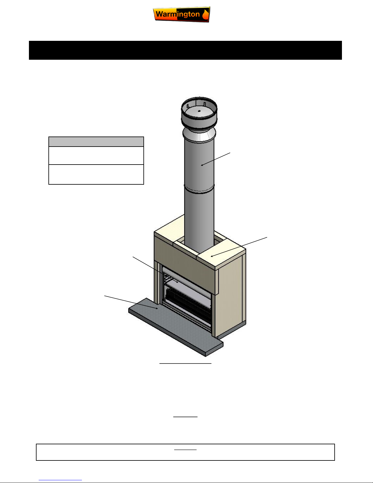
Minimum 2.4m Fluekit
Hebel Heat Cell
(not load bearing)
Warmington Outdoor Nou-
veau Gas Fire & Stainless
Steel cooking tray.
Hearth
Important Notes:
All load bearing structures are
to be engineered to carry load.
Fire for outdoor use only,
NOT to be installed indoors.
The fireplace is constructed and tested to comply with NZS 4558(int):2013 “Decorative gas log and other fuel effect appliances”.
Keep these instructions for further reference. Ensure that you have the correct and current installation details for the Warmington fireplace.
Installation
The Warmington unit is to be installed by a certified Warmington installer or an approved NZHHA installation technician.
See www.homeheat.co.nz/members for a certified NZHHA SFAIT Installer in your area.
A licenced certified gas fitter and licenced electrician are required to run power and gas supplies as required to the unit and any commissioning as part of the
installation process.The heater must be installed according to these instructions and in compliance with all relevant building, gas fitting,
electrical and other statutory regulations.
IMPORTANT
Read all the instructions carefully before commencing the Installation. Failure to follow these instructions may result in a fire hazard and void the warranty
Related documents
Fire and flue system installation, and instructions to comply with NZS 5601.1:2013,
3645.1(Int):2010, 3645.2(Int):2010, 5266:2014, 2918:2001.

23 April 2018
Due to continued product improvement, Warmington Ind LTD reserves the right to change product specifications without prior no tifi-
All Dimension are in mm……. Copyright on all products and Specifications ©
2
POINTS TO CONSIDER PRIOR TO INSTALLATION
Location of the fire. Open fires are better located at one end of a room or area, as they project the heat away from their opening.
Venting to the cavity.
This air is to allow the cavity to vent the warm air. This warm air helps keep the fire and flue system form getting to cold. If the
flue and fire get to cold the system may soot often and require cleaning. Each fire has different ways of venting the cavity.
The Topography of the land .
The slope and position of the land in relation to the home has a bearing on how the wind will interact with the fire and flue sys-
tem. Care needs to be taken to ensure that the flue termination is in the correct position to maximise performance.
The prevailing wind.
Care needs to be taken to ensure that the flue termination is in the correct position as wind and gusts that hits the flue and cowl
system may overcome the cowl and draft back down the flue into the home. This can be a combination of down draft and
high pressure.
Hearth and plinth:
The height of the hearth off the floor. The finishing that is to be used on the hearth is to be allowed for at the design stage.
Positioning of the Flue system:
There is a maximum distance that an offset flue can be installed. Reference to relevant standards.
Flue And Fire Clearance:
To be maintained to the manufactures Instructions.
Installation Notes:
A rebate of 40mm is recommended from the front face of the surround to the front of the fire to reduce the ingress of
water into the fire.
Due to the expansion and contraction of metal fireplaces a 3mm gap between the flange and the finished surround should be
maintained.
Prior to Construction and Installation Important Notes:
Consult a licenced certified gas fitter for correct gas installation.
Install to current standards.
Install to manufacture’s specifications.
All new installations require a permit.
For special requirements concerning materials (timber mantle and surrounds) within close proximity of Warmington products, please con-
tact your local Warmington Technical Consultant.
Stage 1: Frame Construction Procedure by Builder.
Mark out flue centre.
Mark out heat cell clearance requirements.
Construct Plinth only, to required height. *
Stage 2: Install Procedure by Certified “Warmington Installer” only.
Fit Fire to Plinth.
Fit Adaptor to Firebox.
Construct Hebel Enclosure around Nouveau Firebox. (Ensure a 40mm rebate to form a Drip Edge).
Fit Flue System.
Fit Cowl and Flashing System .
Stage 3: Finishing Procedure by Builder.
Construct Hearth to required Thickness. *
Finish Hebel Enclosure and Hearth to Customers requirements (e.g. paint / tiles ).
Close in Hebel Enclosure and Chimney Chase . ( If in Timber Alcove ).
* Note: Certified NZHHA SFAIT Installer can also Install Hearth and Plinth .
Ensure that the Warmington and flue system is swept annually or more frequently if required.
To Sweep Flue and Firebox: Cover Front of Fire with sheets.
Remove Cowl from top of chimney.
Sweep from the top, down the flue.
Remove all soot and ash.
Ensure Cowl and Bird Protection is clean and replaced.
Visually Inspect Fireplace and Flue System
INSTALLATION ORDER OF OPERATIONS
23 April 2018
Due to continued product improvement, Warmington Ind LTD reserves the right to change product specifications without prior no tifi-
All Dimension are in mm……. Copyright on all products and Specifications ©
3
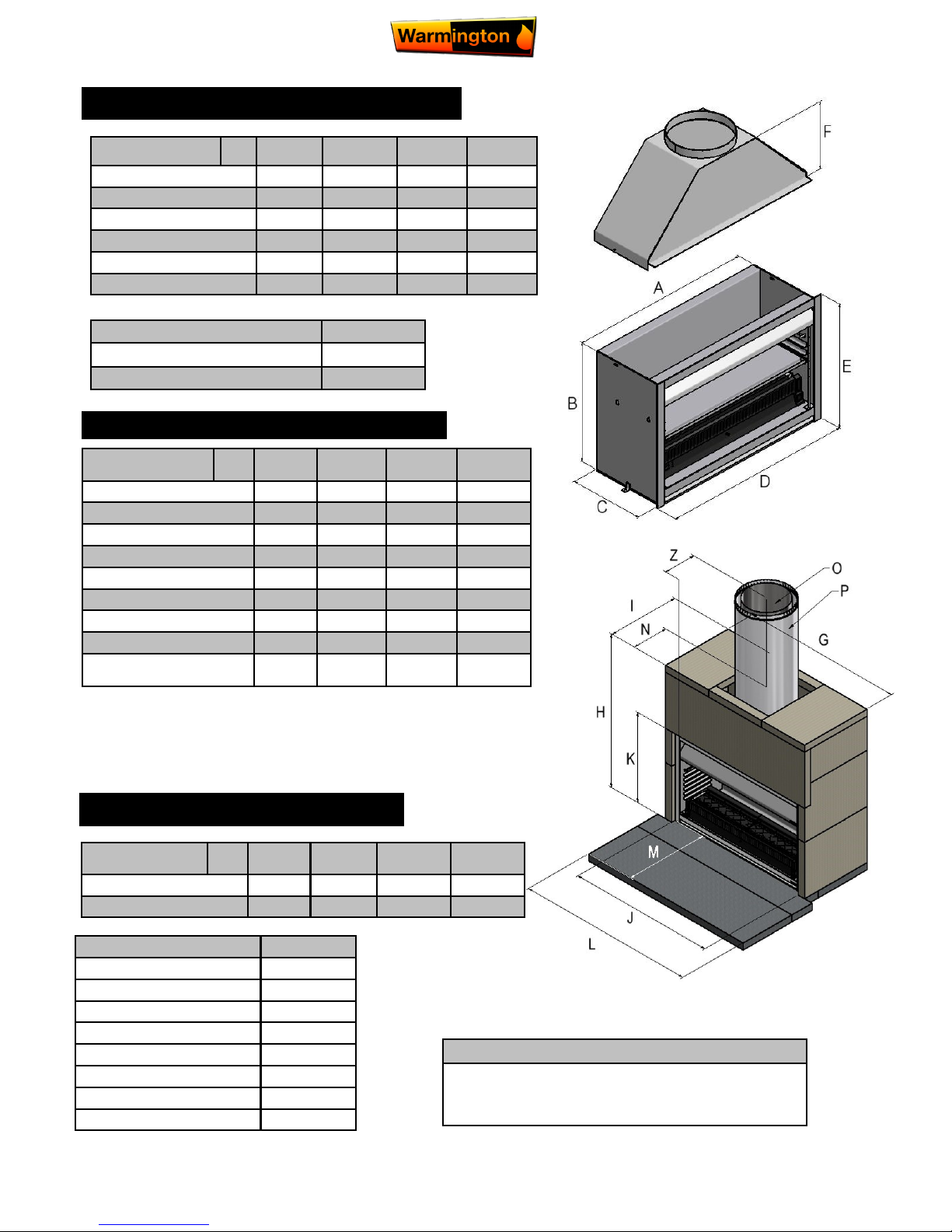
Description
SN 900 SN 1500 SN 1250 SN 1100
Firebox Width A
900 1500 1250 1100
Firebox Height B
760 910 910 760
Firebox Depth C
450 600 600 450
Flange Width D
950 1550 1300 1150
Flange Height E
785 935 935 785
Adaptor Height F
425 480 480 425
WARMINGTON NOVEAU FIREBOX DIMENSIONS
HEBEL SURROUND DETAILS DIMENSIONS
Description
SN 900 SN 1500 SN 1250 SN 1100
Surround Width G
1110 1710 1460 1310
Surround Height H
1325 1640 1640 1325
Surround Depth I
635 770 770 660
Window Width J
960 1560 1310 1160
Window Height K
790 940 940 790
To Centre of Flue N
312 387 448 312
Flue Diameter O
300 450 350 350
Liner Diameter P
400 550 450 450
Flue Centre
(From front face of Firebox Flange )
Z
272 272 408 347
Minimum Flue Height
Flue Height 2400
Measured From Top of Adaptor B + F + 2400
Check List
Firebox
LPG/NG SG Gas Burner
Ash Pan
Rack/Hotplate & Grill
Weather Shield
Badge
Adaptor & Bolts
Packed by
Note:
Firebox is recessed 40mm into Hebel surround.
Timber framing requires no clearances with Hebel surround.
Description
SN 900 SN 1500 SN 1250 SN 1100
Hearth Width L
1450 1900 1650 1650
Hearth Projection M
380 850 850 380
HEBEL HEARTH DIMENSIONS
Note:
• ‘Z’ dimension is from Flue Centre to Firebox Front Flange not in-
cluding 40mm rebate from Hebel Enclosure.
• ‘N’ dimension is from Flue Centre to the Hebel Enclosure front.
23 April 2018
Due to continued product improvement, Warmington Ind LTD reserves the right to change product specifications without prior no tifi-
All Dimension are in mm……. Copyright on all products and Specifications ©
4
PLAN, FRONT ELEVATION & CROSS SECTION
Visit the Warmington website for ‘Hebel’ instruction
PDF sheet at www.warmington.co.nz
This is a general installation guide only – Contact a ‘NZHHA Installer’ for installation advice.
See: www.homeheat.co.nz , choose “members” & pick your Area & Fire type (wood / Gas etc) this will provide you with a
NZHHA Certified Installer (use the SFAIT Installers only).
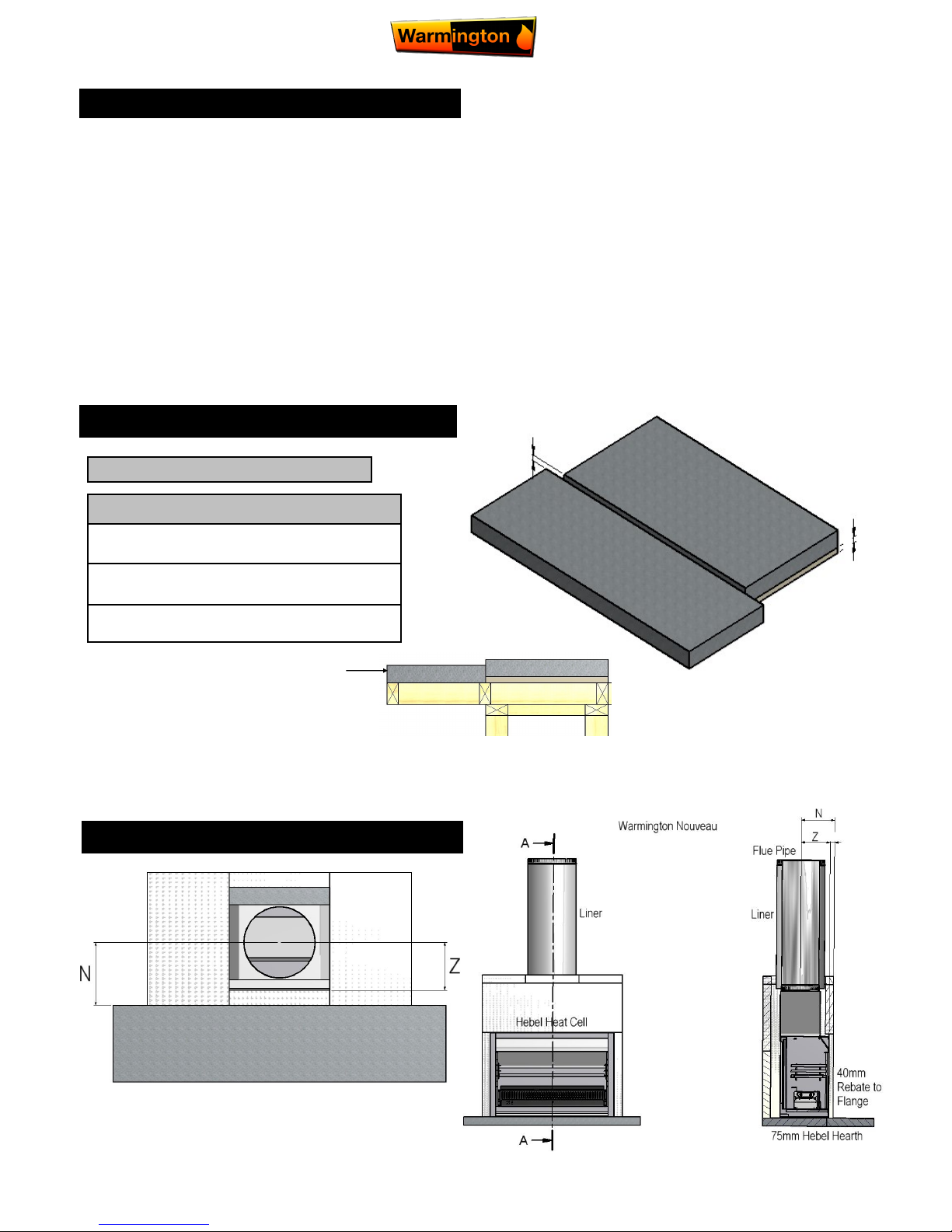
HEARTH & PLINTH CONSTRUCTION DETAILS
1. All the dimensions are minimums
2,. Fit the Plinth into position in the Cavity. If onto a wooden floor ensure that an insulating plinth is fitted as
per the specifications. Ensure that the plinth is elevated to allow for finishing on the hearth. (See
Hearth and plinth details).
1. Fit the firebox into the cavity. Bolt the firebox to the plinth or through to the floor with the bolting point provided on the Left and Right hand sides of the fire box (seismic restraints).
2. Fit the adaptor to the firebox. Ensure that exhaust sealant is used between the fire and adaptor. Bolt into
position with the bolt in the Left and right hand sides of the firebox.
3. Install the flue system.
4. Fit the Hebel Heat cell around the fire. A general minimum lay out is shown in this Specification.
FIREBOX INSTALLATION
Note: Hearth and Plinth Construction
For Combustible flooring an insulating hearth and Plinth
of 75mm Hebel is required.
Plinth to be Offset above Hearth by the Hearth Finishing’s
( e.g. Tiles /Granite /Solid Plaster /etc )
All load bearing cantilevered Hearths must be Engineered
to carry loads.
IMPORTANT NOTE:
Offset
Offset for
Hearth
finishing
*Note: If Solid Plastering the structure, it is recommended to use a Fibreglass Mesh with a Latex Based Solid Plaster to
minimise the chance of the Solid Plaster cracking. (See your Solid Plasterer for correct materials and applications).
This is an example of a raised & cantilevered
Hearth. See page 15 for further raised Hearth
details.
This Hearth
& Plinth setup is at
floor level
Hearth
23 April 2018
Due to continued product improvement, Warmington Ind LTD reserves the right to change product specifications without prior no tifi-
All Dimension are in mm……. Copyright on all products and Specifications ©
5
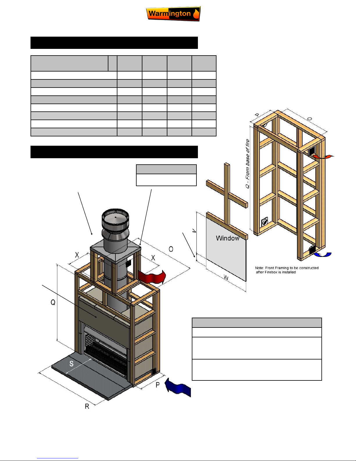
Firebox
SN
900
SN
1100
SN
1250
SN
1500
Frameout Clearance Width O
1170 1370 1490 1770
Frameout Clearance Depth P
665 690 800 800
Frameout Clearance Height Q
2230 2230 2230 2230
Hearth Width R
1450 1650 1650 1900
Hearth Projection S
380 380 850 850
Window Height V
1430 1430 1745 1745
Window Width W
1170 1370 1490 1770
Chimney Chase Clearance X
500 550 550 650
TIMBER FRAMING & TRIM OUT DETAILS
Important Notes:
All framing dimensions are Internal only.
All Timber Framing & Cladding must be
constructed to suit an Outdoor Environment as
per NZ Building Code.
Firebox is recessed 40mm into Hebel
surround. Timber framing requires no
clearance with Hebel surround.
*Note: If Solid Plastering the structure , it is recommended to use a Fibreglass Mesh with a Latex Based
Solid Plaster to minimise the chance of the Solid Plaster cracking. (See your Solid Plasterer for correct
materials and applications).
Window
Height ‘V’
must be
measured
from top of
Hearth .
Hearth Height
MINIMUM HEAT CELL ALCOVE CLEARANCES & FRAME OUT
Note:
Centre Line of Flue is `NOT’ in
Centre of the Chimney chase
A noncombustible
Material must
be used on
front face
of structure -
eg Promina
Board, Superlux, Hebel, etc
See Page 12
for S/S flashing
detail & correct
spigot heights
23 April 2018
Due to continued product improvement, Warmington Ind LTD reserves the right to change product specifications without prior no tifi-
All Dimension are in mm……. Copyright on all products and Specifications ©
6
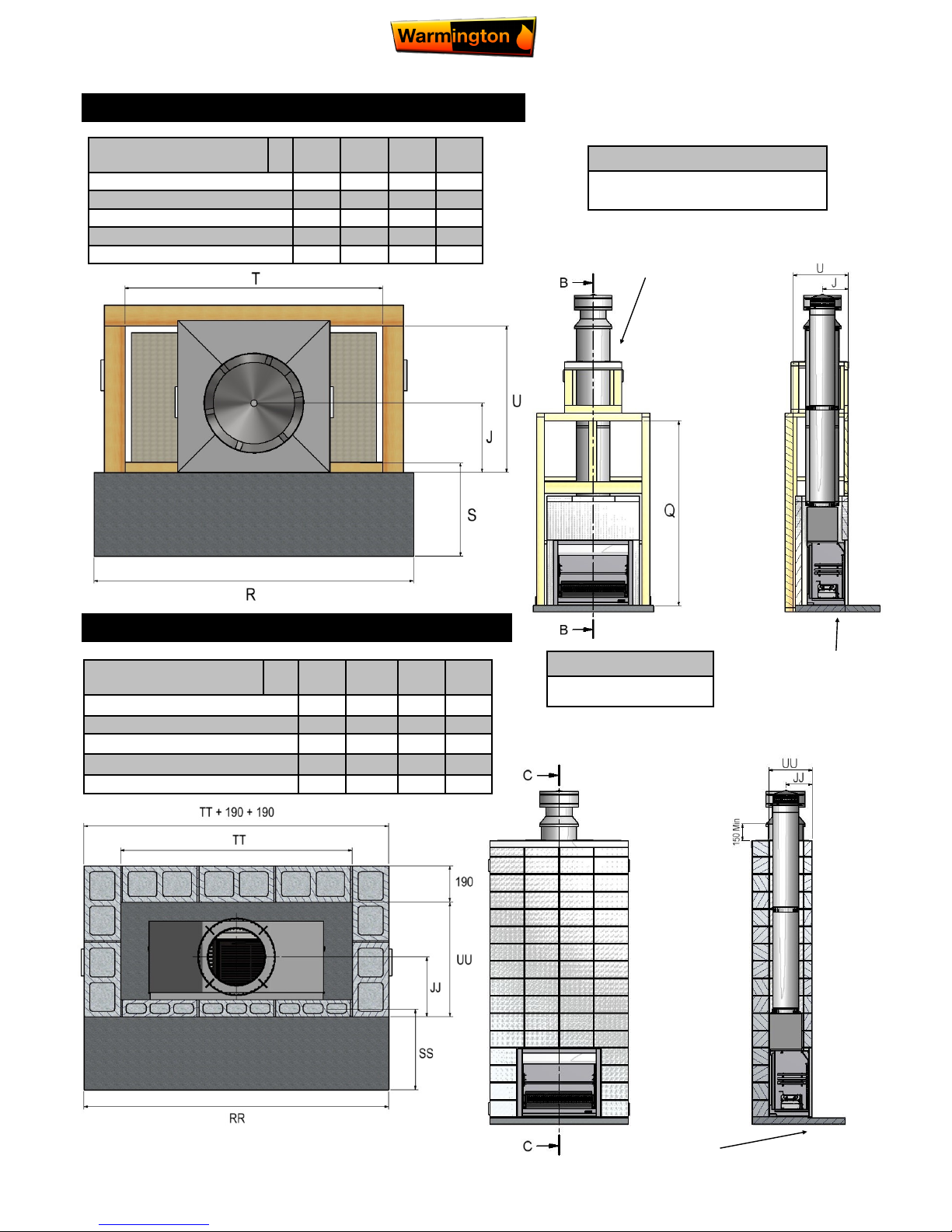
Firebox
SN
900
SN
1100
SN
1250
SN
1500
Hearth Width R 1450 1650 1650 1900
Hearth Projection S 380 380 850 850
Plinth Width T 1170 1370 1490 1770
Plinth Depth U 665 690 800 800
Centre of Flue J 312 312 448 387
BLOCK: PLAN, FRONT ELEVATION & CROSS SECTION
Note:
Centre line of Flue is `NOT’
in centre of alcove
Firebox
SN
900
SN
1100
SN
1250
SN
1500
Hearth Width RR
1590 1650 1650 1900
Hearth Projection SS 380 380 850 850
Plinth Width TT
1210 1210 1610 1610
Plinth Depth UU
600 600 700 700
Centre of Flue JJ 312 312 448 387
TIMBER: PLAN, FRONT ELEVATION & CROSS SECTION
Important Note:
All Load Bearing Structures are
to be Engineered to carry load.
See Page 12 for
S/S Flashing
Detail & correct
spigot heights
See Page 12 for
S/S Flashing
Detail & correct
Spigot Heights
Firebox to be
rebated min
40mm
Firebox to be
rebated min
40mm
20 Series
190mm Block
 Loading...