

Warmington Debonaire DUPLO 1200, Debonaire DUPLO 2000, Debonaire DUPLO 2400, Debonaire DUPLO 2800, Debonaire DUPLO 1600 Installation Instructions Manual
12 September 2016
Due to continued product improvement, Warmington Ind LTD reserves the right to change product specifications without prior no tification.
All Dimension are in mm………….Copyright ©
1
Debonaire DUPLO 1200-1600-2000-2400-2800
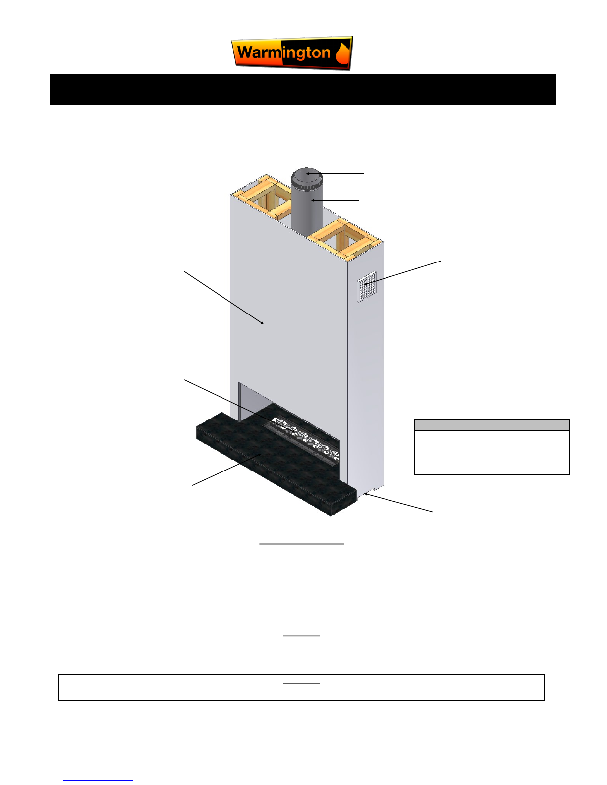
Custom Fire DUPLO — Gas Burner
Installation Instructions
Flue
Liner
Firebox
Venting
Promina Board
Cladding
Non-Combustible
Burner
Hearth
Venting Base Burner
NOTE: T.V. Option Available
Additional Costing for T.V Above Fire-
Consult your nearest Warmington Agent
Visit: www.warmington.co.nz
For Specification
The fireplace is constructed and tested to comply with NZS 4558(int):2013 “Decorative gas log and other fuel effect appliances”.
Keep these instructions for further reference. Ensure that you have the correct and current installation details for the Warmington fireplace.
Installation
The Warmington unit is to be installed by a certified Warmington installer or an approved NZHHA installation technician.
See www.homeheat.co.nz/members for a certified NZHHA SFAIT Installer in your area.
A licenced certified gas fitter and licenced electrician are required to run power and gas supplies as required to the unit and any commissioning as part of the installation
process.The heater must be installed according to these instructions and in compliance with all relevant building, gas fitting, electrical and other statutory regulations.
IMPORTANT
Read all the instructions carefully before commencing the Installation. Failure to follow these instructions may result in a fire hazard and void the warranty
Related documents
Fire and flue system installation, and instructions to comply with NZS 5601.1:2013,
3645.1(Int):2010, 3645.2(Int):2010, 5266:2014, 2918:2001.

12 September 2016
Due to continued product improvement, Warmington Ind LTD reserves the right to change product specifications without prior no tification.
All Dimension are in mm………….Copyright ©
2
POINTS TO CONSIDER PRIOR TO INSTALLATION
INSTALLATION ORDER OF OPERATIONS
Prior to Construction and Installation Important Notes:
1. Consult a licenced certified gas fitter for correct gas installation.
2. Install to current standards.
3. Install to manufacture’s specifications.
4. All new installations require a permit.
5. Allow for gas supply to heat cell at the rear, and power supply to the rear if required.
6. For special requirements concerning materials (timber mantle and surrounds) within close proximity of Warmington products,
please contact your local Warmington Technical Consultant.
Stage 1: Frame Construction Procedure by Builder.
1. Mark out flue centre.
2. Mark out heat cell clearance requirements.
3. Build timber framing to heat cell clearances and chimney chase clearance requirements.
4. Ensure that front face of heat cell clearance alcove is left open and unframed to enable installation of the firebox. The chimney
chase is left unlined for installation of the flue.
5. Construct plinth only, to required height. *
Stage 2: Install Procedure by Certified “Warmington Installer” or Certified Person (Gas Fitter / Plumber)
1. Fit fire to plinth.(Ensure gas supply line is fed through firebox.)
2. Fit flue system.
3. Fit cowl and flashing system.
4. Fit vents to heat cell alcove and chimney chase, to cool the heat cell and ensure efficiency of CAITEC Technology.
Stage 3: Finishing Procedure by Builder.
1. Construct hearth to required thickness. *
2. Finish framing of heat cell alcove.
3. Close in heat cell alcove and chimney chase.
4. Finish heat cell alcove and hearth to customer’s requirements (e.g. paint / tiles).
5. * Note: Certified installer can install hearth and plinth.
Maintenance.
Visually inspect fireplace and flue system.
Ensure that firebox is operated according to manufacture’s instructions.
Location of the fire. Open fires are better located at one end of a room or area, as the y project the heat away from their opening.
Venting to the cavity.
This air is to allow the cavity to vent the warm air. This warm air helps keep the fire and flue system form getting to cold.
If the flue and fire get to cold the system may soot and require cleaning. Each fire has different ways of venting the cavity .
The Topography of the land .
The slope and position of the land in relation to the home has a bearing on how the wind will interact with the fire and flue system.
Care needs to be taken to ensure that the flue termination is in the correct position to maximise performance.
The Prevailing Wind.
Care needs to be taken to ensure that the flue termination is in the correct position as wind and gusts that hits the flue and cowl
system may overcome the cowl and draft back down the flue into the home. This can be a combination of down draft and high
pressure.
Hearth and plinth:
The height of the hearth off the floor. The finishing that is to be used on the hearth is to be allowed for at the design stage.
Positioning of the Flue system:
Flue Systems are to comply with the appropriate standard.
Flue And Fire Clearance:
To be maintained to the manufactures Instructions. Reference the appropriate standard.
Pressure Differential, Venting & External Air into the Building :
All fires need air to burn and draw correctly, Kitchen Fans, Air Conditioning units, High W ind Zones, Naturally forming Draft spaces, can all have an effect on the pressure
difference from inside the building to the outside. A lower pressure in the building may induce a draft down the flue system and back into the building causing the fire to
smoke or spill into the building. Care needs to be taken at the design and installation stage to adequately vent the building, or some mechanical system to ensure
that there is always a neutral or positive pressure at the fireplace and a negative pressure at the flue outlet. Th is will en sure th at t he dr aft in the flu e sy st em is
always to the outside.
“CAITEC AIR” th e li m it s and req ui rem ents. See det ails in th ese Spec ’s , on w ww .war min gt on .co.nz or co ntact you r l ocal Ag ent .
Wind Noise:
You may encounter wind noise in some installations. It is recommended to use an enclosed chase with a chimney pot to help reduce noise. There will always be some
noise from the flue systems of all fireplaces.
12 September 2016
Due to continued product improvement, Warmington Ind LTD reserves the right to change product specifications without prior no tification.
All Dimension are in mm………….Copyright ©
3
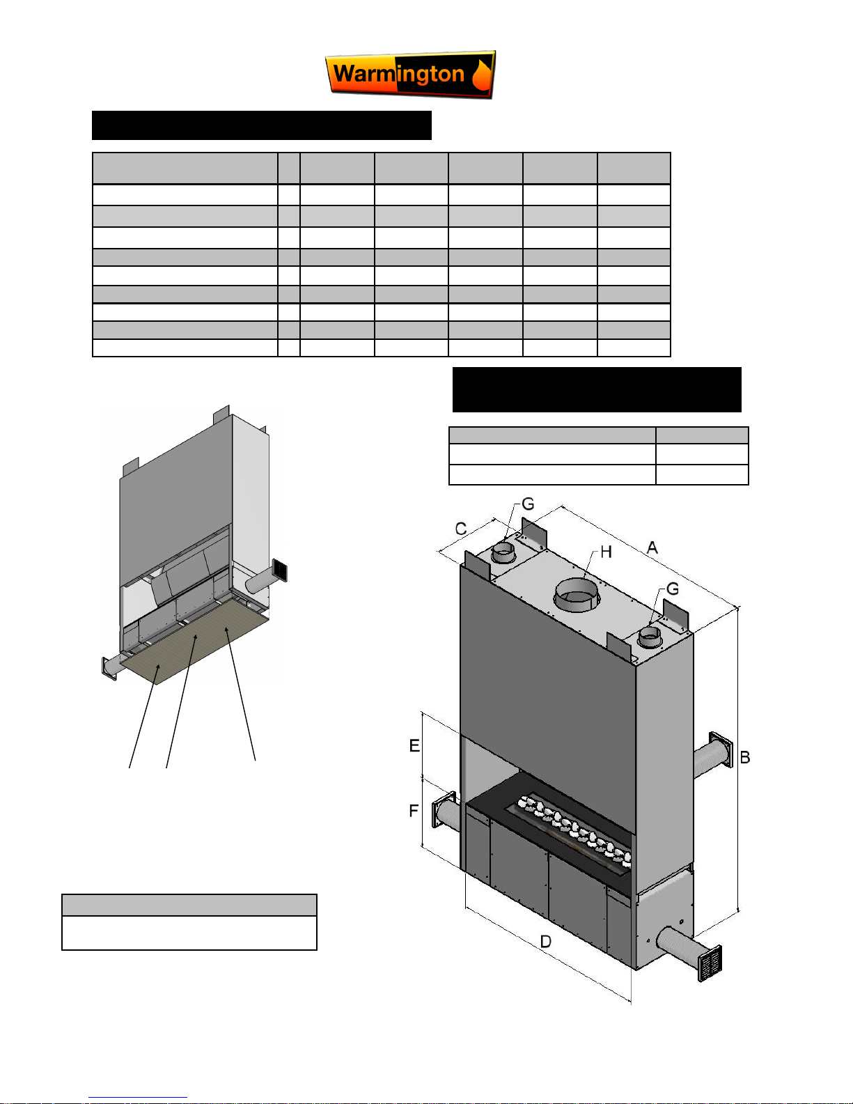
CUSTOM GAS FIREBOX DIMENSIONS
Minimum Flue Height
Flue Height 3600
Measured From Top of Adaptor 3600
HEARTH REQUIREMENTS
TO BE PLACED ON MASONARY FLOOR
Seismic restraint
Secure firebox through
anchor points provided
TOP
FIREBOXBASE
Description 1200 1600 2000 2400 2800
Firebox Overall Width A 1200 1600 2000 2400 2800
Firebox Overall Height B 1800 1800 1800 1800 1800
Firebox Overall Depth C 390 390 390 390 390
Window Width D 1130 1530 1930 2330 2730
Window Height E 400 400 400 400 400
Height from Base F 400 400 400 400 400
Convection Vent Dia G 100 100 100 100 100
Flue Dia. H 200 275 2 x 200 2 x 250 2 x 250
Flue Liner Dia. 250 325 2 x 250 2 x 300 2 x 300
Seismic restraint
Secure firebox through anchor positions through
Base & through bracket at Top of Fire
Builder to supply
Non-Combustible
Base Compressed
sheet To Act as
Seal to Base
12 September 2016
Due to continued product improvement, Warmington Ind LTD reserves the right to change product specifications without prior no tification.
All Dimension are in mm………….Copyright ©
4
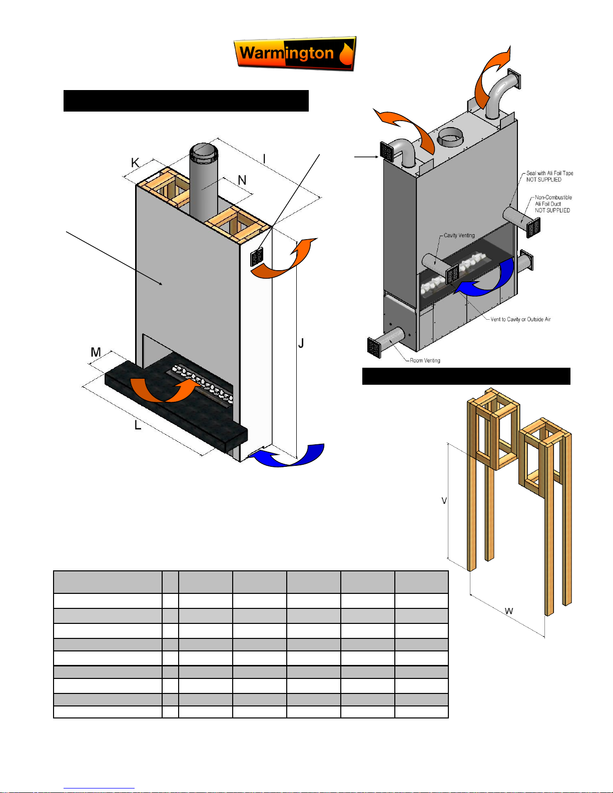
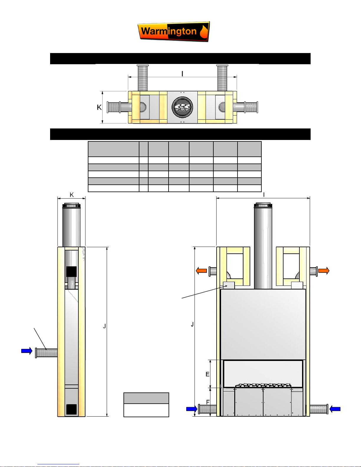
MINIMUM ALCOVE CLEARANCES
FRAMEOUT DETAIL
Description 1200 1600 2000 2400 2800
Overall Timber Width I 1317 1717 2117 2517 2917
Overall Timber Height J 2400 2400 2400 2400 2400
Overall Timber Depth K 390 390 390 390 390
Hearth Width L 1530 1930 2330 2730 3130
Hearth Depth M 300 300 300 300 300
Flue Cavity Depth N 350 425 950 1400 1800
Timber Opening
Opening Height V 1850 1850 1850 1850 1850
Opening Width W 1223 1623 2023 2423 2823
Room Air for
Burner Base
Clad With Promat or other Non-Combustible material
Warm Air
Return to
Room
(Optional
Caitec)
Vent Grill
NOT
Provided
12 September 2016
Due to continued product improvement, Warmington Ind LTD reserves the right to change product specifications without prior no tification.
All Dimension are in mm………….Copyright ©
5
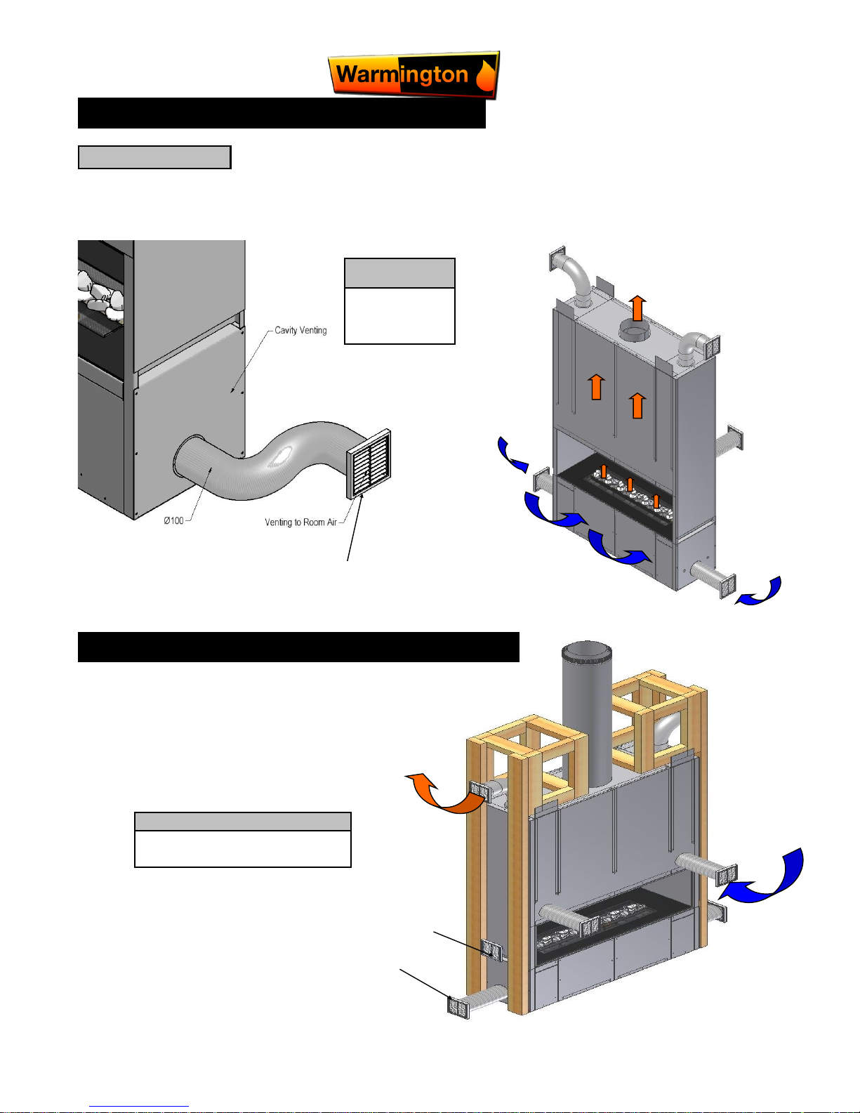
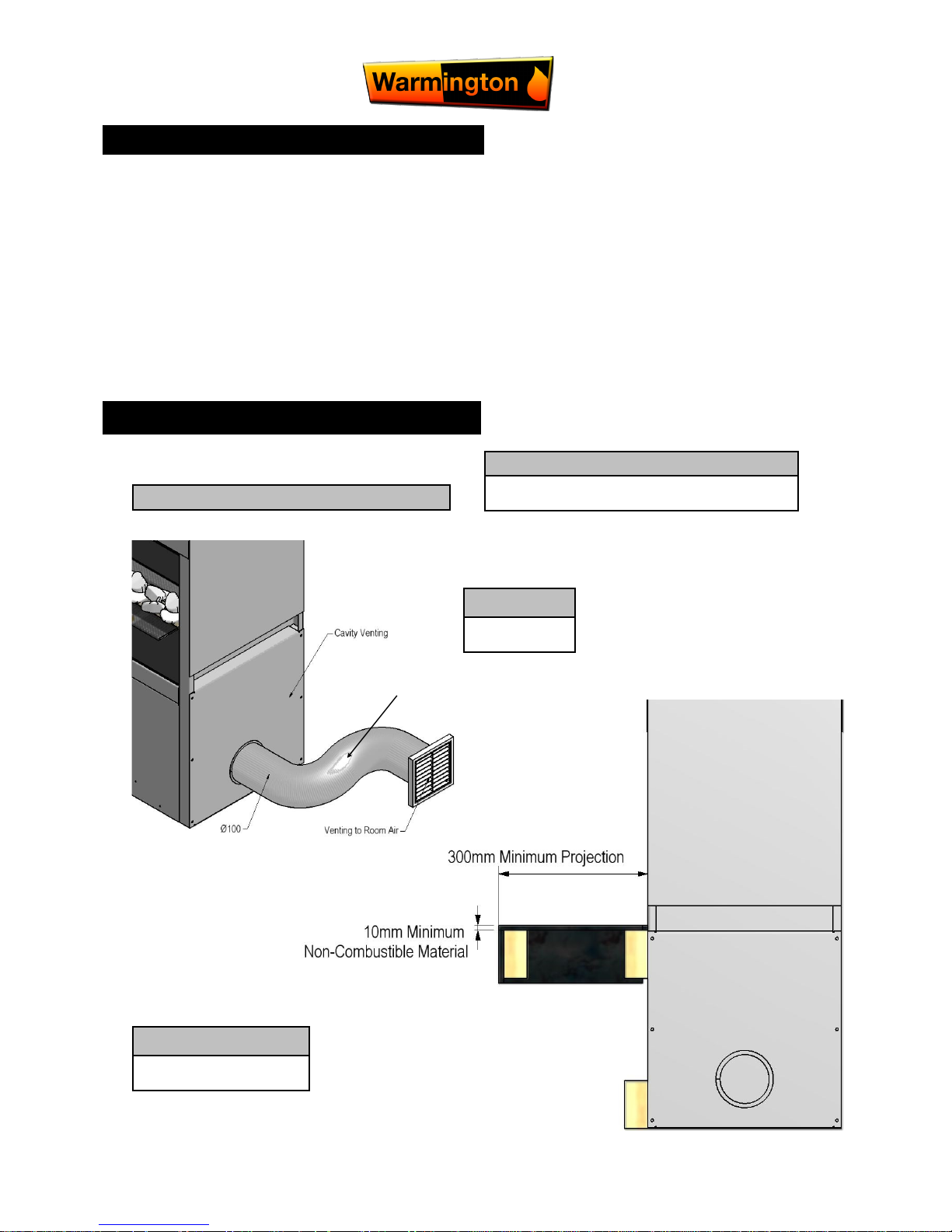
VENTING THE BURNER CAVITY ONLY - General
IMPORTANT NOTE
The Burner and the Burner Base are to be Vented into the same air space. E.G. the
Room that the Burner is taking its air from must be the same as the position of the Vent
for the Burner Base.
The Burner Base must be Vented separately to the Alcove and Flue System
- This is to Avoid the Flames and Heat being drawn from the Fire, Down into the Burner
NOTE
Must be Vented
Separately to the
Cavity
From the Room that the Burner takes its Air from.
The Cavity Venting will allow the Air to
move through the Heat exchanger
Returning Warm Air to the Room.
NOTE
This Cavity Air Must Not be Vented to the
Burner Cavity
Cavity Venting Only
Burner Base Venting Only
Burnt Gases Travel up
Flue System
Burnt Gases
Main Burner Air from Room
Burner Base Air
Supply
Burner Base Air
Supply
VENTING THE CAVITY & VENTS FOR CONVECTION AIR - General
12 September 2016
Due to continued product improvement, Warmington Ind LTD reserves the right to change product specifications without prior no tification.
All Dimension are in mm………….Copyright ©
6
FIREBOX INSTALLATION
This is a general installation guide only – Contact a “NZHHA Installer” or Gas Fitter for Installation Advice.
1. All the dimensions are minimums
2. Fit the Plinth into position in the Cavity. If onto a wooden floor ensure that an insulating plinth is fitted as per
the specifications. Ensure that the plinth is elevated to allow for finishing on the hearth. (See Hearth and
plinth details)
3. Fit the firebox into the Cavity. Bolt the fire box to the plinth or through to the floor with the bolting point provided on the Left and Right hand sides of the fire box (seismic restraints).
4. Install the flue system.
HEARTH & PLINTH CONSTRUCTION DETAILS
Note: Hearth and Plinth Construction.
Plinth to be off set above hearth by the hearth finishing’s
( e.g. tiles / granite / plaster / etc )
IMPORTANT NOTE :
Cut to Length
Aluminum Foil Duct
NOT SUPPLIED
Note:
Vent & Duct
NOT SUPPLIED
Vent NOT SUPPLIED
Note:
Hearth to be Constructed as
Per Specification
12 September 2016
Due to continued product improvement, Warmington Ind LTD reserves the right to change product specifications without prior no tification.
All Dimension are in mm………….Copyright ©
7
PLAN
FRONT ELEVATION & CROSS SECTION
Firebox is to be Bolted
to Supporting Framing
or Block Work
Vent & Duct
NOT SUPPLIED
Warm Air &
Cavity Venting
Note:
Hearth Details Not
Shown see Page 5
Description 1200 1600 2000 2400 2800
Window Height E 400 400 400 400 400
Base Height F 400 400 400 400 400
Outside Framing I 1317 1717 2117 2517 2917
Framing Height J 2400 2400 2400 2400 2400
Framing Depth K 390 390 390 390 390
12 September 2016
Due to continued product improvement, Warmington Ind LTD reserves the right to change product specifications without prior no tification.
All Dimension are in mm………….Copyright ©
8
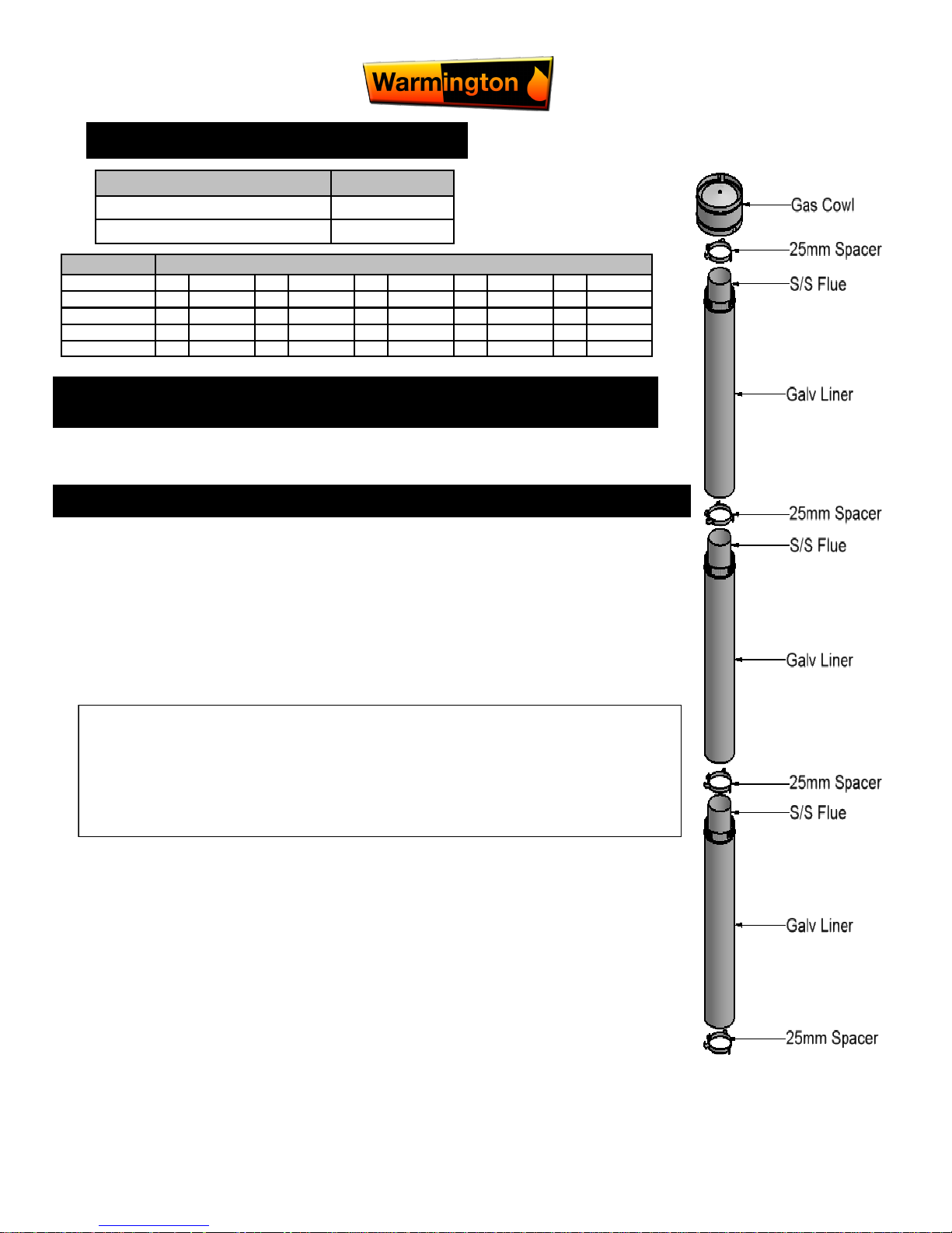
FLUE DETAILS DIMENSIONS Double Flue System
Minimum Flue Height
Flue Height 3600
Measured From Top of Adaptor 3600
NOTE: Ensure that a Standard Tested Warmington Flue system is used on Warmington fires.
GENERAL FLUE SYSTEM INSTALLATION GUIDE ONLY ( MAY VARY ON SITE INSTALL )
ANY OPENING OR CAVITY MUST BE MORE THAN 1 METER AWAY FROM WHERE
EXHAUST GASES ARE PRESENT.
Flue details No: 1200 1600 2000 2400 2800 No: No: No: No:
Cowl 1 200 275 200 250 250 1 2 2 2
Spacer 3 200 275 200 250 250 3 6 6 6
Flue Diameter 3 200 275 200 250 250 3 6 6 6
Liner Diameter 3 250 325 250 300 300 3 6 6 6
Bottom Spacer 1 200/250 275/325 200/250 250/300 250/300 1 2 2 2
This is a general installation guide only – Contact a “NZHHA Installer” for Installation Advice.
1. Install the first length of flue pipe with the crimped end down, inside the Adaptor collar, ensure that the
flue pipe is sealed into the collar with exhaust sealant. Rivet the flue in 3 places around the Adaptor
collar. Place a bottom spacer around the flue pipe approximately 150mm above the adaptor collar.
Secure in position by tightening the screw and nut.
2. Install the second length of flue pipe with the crimped end down and fit by riveting in at least 3 places
around the flue pipe joint. Ensure that the flue is sealed into position with sealant.
3. Install the first section of flue pipe liner with the Crimped end up, over the flue pipe and over the spacer
that is fixed to the flue pipe. This spacer will keep the liner concentric about the flue pipe.
4. Position flue spacer at the flue pipe joint for every length of “Flue pipe” and “Liner”.
Repeat the Steps from 1 – 4 to the installed required height of the flue system. The flue system is to
comply with the current standards.
IF FLASHING CONE NEEDED
1. NOTE: The last lengt h o f flue pipe n eeds to extend p ast th e liner s o that w hen the “ top spid er”
and the “Flashing cone” are fitted, that the “flashing cone” and the “flue pipe” are flush, or that the “flue
pipe” is 5mm lower that the “Flashing cone”.
2. Fit the “Top Spider” into position, ensure that the legs of the spider are fitted inside the liner and that the
spider is positioned hard down onto the liner and tighten with the screw and nut.
3. Place the “Flashing cone” over the “flue pipe” and press hard down onto the “Top Spider”. (Note that the
“Flue pipe” and the “Flashing Cone” are either flush or the “Flue pipe” is 5mm Lower than the “Flashing
cone”.) Ensure that the “Flashing cone” is clear for the venting from the “Liner” and the “flue pipe”.
4. Fit the “Cowl” to the top of the flue pipe. The “Cowl”, “Flashing cone”, and the “Flue pipe” can be secured
to each other with the uses of a stainless steel self tapping screw. This will allow the “Cowl” to be removed for cleaning.
5. Flue system may require Bird Proofing due to the installation and locations, discuss this with your installer for the best advice.
6. If the Flue system is installed into a “Chimney Chase”, allow for air vent as close to the top of the chase
as practical, or allow venting through the “Chimney Chase Flashing”. A “Venting Flashing cone” and a
25mm gap around the Liner with a “Venting Flashing Cone-Spider” can be used. Ref : to Figures ……
In this Specification
a “the flue pipe shall extend not less than 4.6m above the top of the floor protector.”
b “ the minimum height of the flue system within 3 m distance from the highest point of the roof shall be 600mm
above that point.”
c “the minimum height of the flue system further than 3 m from the highest point of the roof shall be 1000mm
above the roof penetration.”
d “no part of any building lies in or above a circular area described by a horizontal radius of 3 m about the flue
system exit.”
 Loading...