

Warmhaus VIWA 50, VIWA 65 Installation & User Manual

VIWA 50
VIWA 65
WALL MOUNTED CONDENSING BOILERS
INSTALLATION & USER MANUAL
Viwa 50
Viwa 65

CONTENTS
1. DEAR WARMHAUS
CUSTOMER
1.1. GENERAL WARNINGS
1.2. TERMS AND CONDITIONS OF
WARRANTY
1.3 GAS LEAKS
1.4 BOILER GAS CATEGORIES &
REGIONS
2. INSTALLATION PERSONNEL
SECTION
2.2. BOILER INSTALLATION RULES
2.2.1. General Rules For Installatıon Place Of
The Boiler
2.2.2. Places Where Hermetic Boilers Cannot
Be Installed
2.2.3. Mounting Of The Boiler To Wall And
Selection Of Installation Place
2.2.4. Dimensions And Connections
2.2.5. Natural Gas And Lpg Connection
(Appliance Category I2h, Ii2h3p)
2.2.6. Flammable Gas Quality
2.2.7. Heating And Domestic Hot Water
Installations
2.2.8. Filling The Flusher For Condensation
Line
2.2.9. Exhaust Gas Flue Pipe Set And
Accessories Connection
2.2.10. Filling The Flusher For Condensation
Line
2.2.11. Exhaust Gas Flue Pipe Set And
Accessories Connection
2.2.12. Peripheral Distances Of The Flue
Outlet Connections
2.2.13. Installation With Vertical Concentric
Flue Sets
2.2.14. Installation With Vertical Concentric
Flue Sets
2.2.15. Use Of Split Flue Type (Hermetic)
2.2.16. Installation At Partially Protected
Outsides
2.2.17. Electrical Connections
2.2.18. Optional Controls: Room Thermostat,
Outside Temperature Sensor And
Others
2.3. HYDRAULIC INSTALLATION RULES
2.3.1. Heating System Water
2.3.2. Filling/Draining The Heating System
2.3.3. Circulation Pump
2.3.4. Checks For Start-Up Of The Boiler
2.3.5. Components Of The Boiler
3. FOR USERS
3.1. GENERAL WARNINGS FOR USERS
3.1.1. Use Of The Boiler
3.2. SELECTION OF ONOFFSTANDBY
AND SUMMER WINTER MODES
3.2.1. On/Off/Stand-By Positions
3.2.2. Operation In Winter Mode
3.2.3. Operation In Summer Mode
3.2.4. Resetting The Boiler (Restart)
3.2.5. Turning Off The Boiler
3.2.6. Selection Of On/Off/Stand-By And
Summer/Winter Modes
3.2.7. On/Off/Stand-By Positions
3.2.8. Operation In Winter Mode
3.2.9. Operation In Summer Mode
3.2.10. Turning Off The Boiler
3.2.11. Use With Room Thermostat (Optional)
3.2.12. Use Of Outside Temperature Sensor
(Optional)
3.2.13. Customization Of Boiler Functions
3.3. TROUBLESHOOTING
3.3.1. Error Codes Table
3.4. RECOMMENDATIONS FOR
ECONOMICAL USE OF THE BOILER
3.5. MATTERS TO PAY ATTENTION FOR
GUARANTEE CONDITIONS
3
1. DEAR WARMHAUS CUSTOMER
We congratulate and thank you for choosing Warmhaus wall mounter
boiler which shall provide you heating and domestic hot water
comfort for years. State-of-art Warmhaus boilers, being manufactured
in compliance with standards of the European Union are also
exported to many countries. You can utilize our Authorized Technical
Service network with professional competence certification for any
ordinary maintenance needs of this product produced meticulously
with hard work. Our authorized services assure sustaining performance
of the device as they shall always provide original spare part services.
Please read this manual thoroughly to use your boiler economically,
comfortably and efficiently, and store to refer when needed.
It is recommended for efficient use to have assembly done by an
authorized dealer approved by the local gas authority and which has
the competence and experience for assembly.
1.1. GENERAL WARNINGS
This manual is an integral part of the product, and must be delivered
to the new user in case of handover of the appliance. The manual
shall be preserved properly and kept in the way to be referred as it
contains significant information about use as well as installation of the
appliance.
Heating and Domestic Hot Water installations shall be
projected and implemented a competent and approved
engineering company meeting the criteria prescribed by laws,
by observing the current legislation in force.
Installation and maintenance shall be carried out by the
competent personnel having sufficient knowledge in the
installation industry and professional competence certification
in accordance with the legislation in force and in line with the
directions of the manufacturer. Hazards which may cause injury of
persons, other living beings (animals, plants) and damage to goods
may be caused by wrong installation, for which the manufacturer
cannot be held responsible.
Natural gas installation project; shall be carried out by one
of the dealers authorized by your local gas authority.
1.2. TERMS AND CONDITIONS OF WARRANTY
The manufacturer may not be held responsible for any
faults caused by noncompliance to the legislation and
standards in force and information provided in this manual
(and information and instructions provided by the manufacturer in
any case), within or out of the scope of the contract, and this also
constitute reason for termination of warranty of the appliance.
Only Warmhaus Authorized Service is authorized to carry out
electrical connection of the boiler and to energize the boiler.
In case of any material, design or installation faults occurred within
the warranty period, maintenance and operation shall be carried out
without any charge of labor or spare parts.
(Also see: 3.5 MATTERS TO PAY ATTENTION FOR GUARANTEE
CONDITIONS)
This appliance should only be used for its designed intended
purposes (to be used in closed-circuit heater installation and
production of open circuit domestic hot water production).
. All kinds of other uses are not suitable as well as may create a
potential danger.
Manufacturer shall not be responsible for damages
occurring due to interventions, false installation and initial
starting performed by unauthorized persons and warranty
scope shall be void. As the Combi is an appliance having heating
system, domestic hot water, natural gas/LPG and electrical
connections, do not make and have any interventions made without
the authorized service
This appliance maintenance operations should be performed
by the authorized and competent technical personnel, and
Warmhause Authorized Technical Service Centers constitute
assurance for quality. WARMHAUS is not responsible for damages
arising from repairs, part replacements and maintenance performed by
third persons and companies and combi remains out of the warranty
scope under such conditions.
Attention! Please note & read the warning and informations on the
boiler. Incorrect operation of the boiler can cause significant damage.
For Warmhaus wall-mounted boilers; commissioning, adjustment,
maintenance and cleaning must only be carried out by a specialist OR
approved service by Warmhaus!
When faults occur in the heating system, the plant must be stopped
and damaged parts should only be replaced by an authorized
workshop.
The accessories used must correspond to the technical rules and the
relevant parts must be approved by the manufacturer in connection
with the Warmhaus wall-mounted boiler.
Only APPROVED & ORIGINAL spare parts should be used.
Bolts sealed with paint strictly forbidden to open !
The boiler must not be used by children younger 8 years or
invalid persons without supervision.
These seals provide evidence that the replacement of bolts required
for safe operation. If the seals are damaged, the guarantee of the
device will come to an end!
This appliance has been manufactured to be installed in the
country specified on its technical registration label. Installing
the appliance in any other country than those specified on
the plate may cause damage or injury to persons, animals and goods.
WARMHAUS declares that Viwa 50 & 65 boilers comply with the
essential requirements of the following directives:
- Gas Appliances Regulation (EU) 2016/426
- Boiler Efficiency Directive 92/42/EEC
- Electromagnetic Compatibility Directive 2014/30/UE
- Low Voltage Directive 2014/35/UE
- Ecodesign Directive 2009/125/EC
- Regulation (EU) N. 813/2013 - 811/2013
4

Manufacturer: Warmhaus Isıtma ve Soğutma Sistemleri Tic. A.Ş. Bursa
Teknik resmin orjinal boyutu A3'dür
Organize Sanayi Bölgesi Park Cad. No:10 16140 Nilüfer-Bursa / Turkey
WARMHAUS
50 kW
65 kW
1015 18
1015 18
WARMHAUS A.Ş. reserves the right to make all kinds of technical and commercial modifications without notice, and disclaims any liabilities arising
out of printing and spelling mistakes.
IMPORTANT INFORMATION
It is a statutory requirement that all gas appliances are installed by competent persons, in accordance with the gas safety (installation and use)
regulations (current edition). The manufacturer's instructions must not be taken as overriding any statutory requirements, and failure to comply
with these regulations may lead to prosecution. No modifications to the appliance should be made unless they are fully approved by the
manufacturer. Gas leaks: do not operate any electrical switch, or use a naked flame. Turn off the gas supply and ventilate the area by opening
doors and windows contact the gas emergency service
1.3. GAS LEAKS
187 NATURAL GAS EMERGENCY LINE
HOW TO ACT IN CASE OF DETECTING NATURAL GAS ODOR
Do not use
lighter- matches
Do not turn on, off
or unplug the lamps
or other electrical
appliances.
Ventilate the
environment by
opening doors and
windows.
Close valves of
appliances operating with natural gas
and your gas meter
Do not use/let
anyone use the
doorbell.
IN EMERGENCY CASES
NATURAL GAS
EMERGENCY
FIRE
DEPARTMENT
Do not use phones
in case of a natural
gas leakage. It may
create sparks.
YÜZEY İŞLEMİ
YÜZEY KALİTESİ
A
Boyalı
1. Dereceden görünür yüzey
Kaplamalı
B
2. Dereceden görünür yüzey
Kaplamasız
C
3. Dereceden görünür yüzey
Immediately evacu-
ate the place with
Lawa
Lawa Plus
150.11.606.000001
1000
592 mm
80 mm
(OPTIONAL)
65 mm
ga s o d or.
Priwa / Priwa Plus
Enerwa / Enerwa Plus
Ø110 mm
Ø110 mm
422 mm
725 mm
GAS
G1/2"G1/2"
G3/4" G3/4"G3/4"
65 mm 64 mm
73 mm
75 mm
471
114 mm
94 mm
G. EKER0122.02.2018
REVZ. YAPAN
REV.NO
TARİH
G. EKER
Çizen /Drawn
E. BİNER
Kontrol /Approved
İ. TAŞDEMİR
Onay /Drawn aut.
22.11.2017
Tarih / Date
Aksi belirtilmeyen genel tolerans için ISO 2768-M geçerlidir.
>
>
±0,1 mm
6 30 mm
0,5 3 mm
>
±0,125 mm
3 6 mm
>
30 120 mm
Bu teknik resmin tüm hakları Warhaus'a aittir. Firmanın yazılı izini ve bilgisi olmaksızın üçüncü şahıslarla paylaşılması ve ürettirilmesi yasaktır.
All rights reserved. This drawing is Warmhaus' intellectual property. It's forbidden to reproduce or forward it to any third part without written authorization .
Call the Natural Gas
Emergency Line from
your neighbor or ano-
ther suitable place.
Yoğuşmalı modellerde baca yükselikiği değiştiği için ilave delik yeri eklendi.
AÇIKLAMA
İmza
Isıtma ve Soğutma Sistemleri Sanayi Ticaret A.Ş.
Bursa Organize Sanayi Bölgesi Park Cadde No: 10
(www.warmhaus.com.tr)
Nilüfer / BURSA - TURKEY
Montaj Şablonu
Parça Adı :
471x1000mm Kağıt
Malzeme :
CP00205
Resim No:
>
±0,5mm
120 400 mm
±0,2 mm
>
400 1000 mm
±0,3 mm
150.11.606.000001
Logo Kodu:
±0,8mm
AMBULANCE POLICE
Do not intervene the
installation Wait for
Gas Authorities Team
to arrive.
Never close culverts
ensuring discharge of
the gas from the en-
vironment in case of a
natural gas leakage.
INFORMATION: You can visit web sites of
local gas authorities and NATURAL GAS
EMERGENCY sections.
Advice: Please take note local emergency
phone numbers.
1.4. CONTENTS OF THE PACKING BOX
Warmhaus is delivered in two boxes as Boiler and Flue Set Box. The Boiler box
contains the materials listed below and the small box contains
I. Installation Scheme (Figure 1)
II. Operation Manual (Figure 2)
III. Connection Accessories (Figure 3)
a. 1 throttle screw (installed at flue outlet.)
b. 2 hanger screws
c. 2 Dowels
IV. Hanger Plate (Figure 4)
İmza
1:5
Ölçek
Rev.No
0.0
V. Exhaust Gas Flue Set (optional) (Figure 5)
A3
Ölçü birimi: MM
Figure 2 Operation Manual Figure 5 Exhaust gas flue set
Figure 1 Installation scheme
Figure 3 Connection Accessories
Figure 4 Hanger Plate
Keep packaging materials (plastic, bag, nylon, etc.) away from
children in order to avoid risks to health.
5
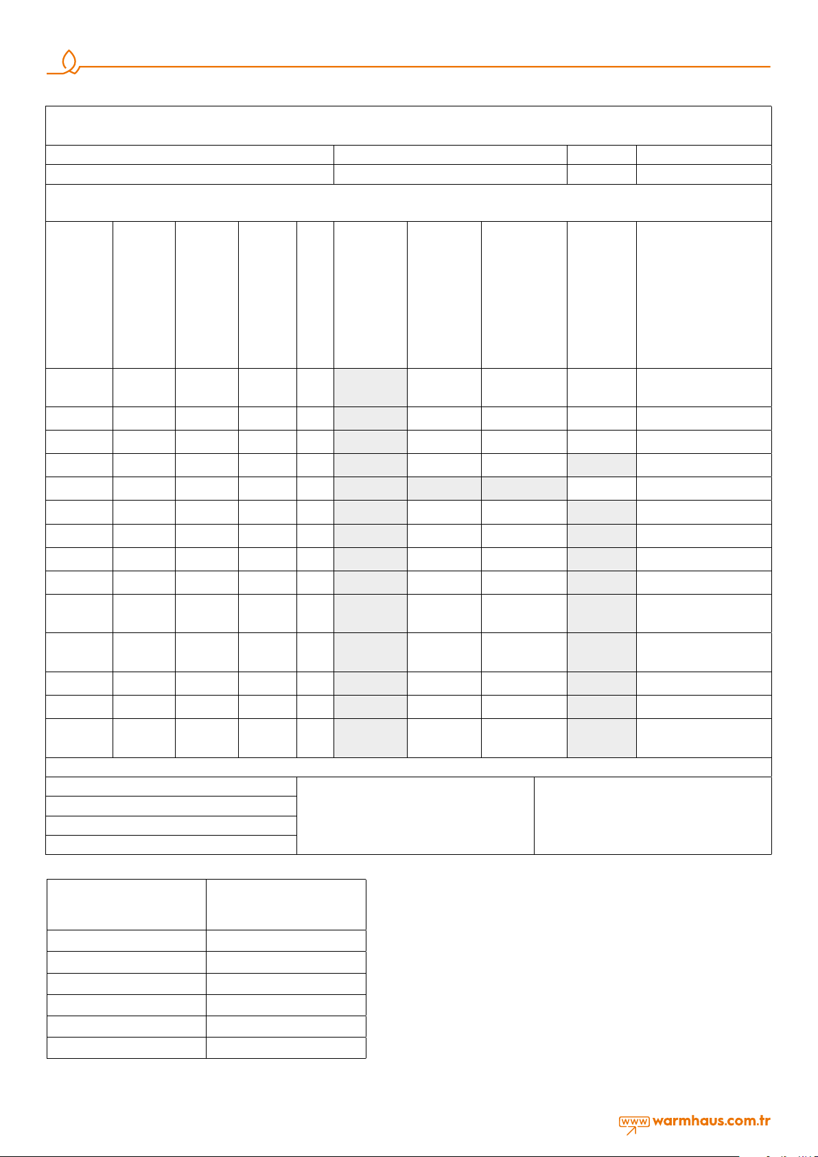
1.4 BOILER GAS CATEGORIES & REGIONS
Designation: Used gas types & Countries
Manufacturer Type Model / Technical Data Conformity Markings
Boiler Gas Categories & Regions Wall mounted type Warmhaus combis and boilers granted
Gas categories for Warmhaus boilers are implemented on the CE certificate given below by SZU Test / BRNO;- appliance categories according to direct destinations are determined in
accordance with EN 15502-1. According to-EN ISO 3166-1 destination countries;- millibar gas supply pressures, can be used for several gas groups if it is under normal pressure. They are
specified with numerical values and "mbar" unit.
Enerwa 24
Enerwa 2530
Document for
conformity
approved by
SZU test
YES I 2H Natural Gas 20 mbar G20 Not Approved Approved Approved Approved
YES I 2H Natural Gas 25 mbar G20 Not Approved Approved Approved Approved HU
YES I 2E Natural Gas 20 mbar G20 Not Approved Approved Approved Approved DE, LU, PL, RO
YES I 2E+ Natural Gas 20 mbar G20 Not Approved Approved Approved Not Approved BE, FR
YES I 2E(S) Natural Gas 20 mbar G20 Not Approved Not Approved Not Approved Approved BE
YES I 2E+ Natural Gas 25 mbar G25 Not Approved Approved Approved Not Approved BE, FR
Appliance
Categories
Gas Type
Gas Inlet
Supply
Pressures
Used
Gas
Lawa 24
Lawa Plus 24
Lawa 28
Lawa Plus 28
Priwa 24
Priwa Plus 24
Priwa 28
Priwa Plus 28
Priwa 33
Priwa Plus 33
Enerwa Plus 24
Enerwa Plus 2530
Enerwa 28
Enerwa 3035
Enerwa Plus 28
Enerwa Plus 3035
Enerwa 33
Enerwa 3540
Enerwa Plus 33
Enerwa Plus 3540
Viwa 50
Viwa 65
Viwa 90
Viwa 115
Viwa 125
Viwa 150
Countries of
Destination **
AT, BG, CH, CZ, DK, EE, ES, FI,
GB, GR, IE, IT, LT, LV, NO, PT, RO,
SE, SI, SK
YES I 2L Natural Gas 25 mbar G25 Not Approved Approved Approved Not Approved NL
YES I 2ELL Natural Gas 20 mbar G20 Not Approved Approved Approved Not Approved DE
YES I 2ELL Natural Gas 20 mbar G25 Not Approved Approved Approved Not Approved DE
YES II 2H3P Natural Gas 20 mbar G20 Not Approved Approved Approved Not Approved
YES II 2H3P Propane LPG 37 mbar G31 Not Approved Approved Approved Not Approved
YES II 2L3P Natural Gas 25 mbar G25 Not Approved Approved Approved Not Approved NL
YES II 2L3P Propane LPG 37 mbar G31 Not Approved Approved Approved Not Approved NL
YES I 3P Propane LPG 37 mbar G31 Not Approved Approved Approved Not Approved
EN ISO 3166-1: 2006, Codes for the representation of names of countries and their subdivisions - Part 1: Country codes (ISO 3166-1: 2006)
Prepared by: İsmail B.Taşdemir / R&D Mng.
Date of Publication: 18/4/2017
Rev. No: 2
Drw. No: WH.17.107
Table 1.1
Product Name (as on product
data badge & installation
instructions)
Approval; revision was made with E-30-00300-18 GAR
certificate and CE-1015CT0615 product number. And
correction 02 Viwa 50 and 150 kW addition equivalent.
G.C. No Allocated by
British Gas**
This document and the information contained herein
belong to Warmhaus Isıtma ve Soğutma Sistemleri San.
Tic. A.Ş. It shall not be transferred to any person not
authorized by Warmhaus Isıtma ve Soğutma Sistemleri
San. Tic. A.Ş. or copied or used howsoever by any third
persons without prior written approval.
CH, CZ, ES, FR, GB, GR, IE, RO,
CH, CZ, ES, FR, GB, GR, HR, IE,
BE, CH, CZ, ES, FR, GB, GR,
HR, IE, IT, LT, NL, PL, PT, RO,
Enerwa 2530 47-786-01
Enerwa Plus 2530 47-786-02
Enerwa 3035 47-786-03
Enerwa Plus 3035 47-786-04
Enerwa 3540 47-786-05
Enerwa Plus 3540 47-786-06
Table 1.2
SI, SK
IT, LT, PT, RO, SI, SK
SI, SK, TR
6
2. INSTALLATION PERSONNEL SECTION
70
04
158
765
207
124
127
207
127
725
30
385
420
40
100
121,5 105,5 90
88,5
136
MODE
RESET
+
-
-
+
1
2
3
4
5
6
7
9
10
11
12
13
1415
16
17
18
Kalorifer Gidiş
G1 1/4
Kalorifer Dönüş
G1 1/4
GAZ
G 3/4
1
2
9
8
7
6
5
4
3
10
11
12
13
14
15
16
17
230V AC MAIN SUPLLY
MANOMETER
PRESSURE RELIEF VALVE OUTLET
GAS INLET
CENTRAL HEATING FLOW (CH)
CENTRAL HEATING RETURN (CH)
CONDANSATE DRAIN
CH/DHW MODE PUSH BUTTON
DIRT COLLECCTOR DRAIN
CH TEMPERATURE - ADJ. BUTTON
LCD DISPLAY
SERVICE ACCESS POINT
RESET BUTTON
DHW TEMPERATURE + ADJ. BUTTON
DHW TEMPERATURE - ADJ. BUTTON
FLUE OUTLET
MOUNTING BRACKET
18
CH TEMPERATURE + ADJ. BUTTON
8
İmza
E. BİNER
İ. TAŞDEMİR
Aksi belirtilmeyen genel tolerans için ISO 2768-M geçerlidir.
Onay /Drawn aut.
Kontrol /Approved
Çizen /Drawn
Tarih / Date
0.0
Rev.No
Ölçek
10.01.2018
YÜZEY KALİTESİ
Kaplamasız
Kaplamalı
Boyalı
YÜZEY İŞLEMİ
G. EKER
Isıtma ve Soğutma Sistemleri Sanayi Ticaret A.Ş.
Nilüfer / BURSA - TURKEY
(www.warmhaus.com.tr)
Bursa Organize Sanayi Bölgesi Park Cadde No: 10
WARMHAUS BOILER (CH ONLY)
Viwa 50/Viwa 65
2.1. BOILER INSTALLATION RULES
2.1.1. General Rules for Installatıon Place of the Boiler
There are not any ventilation limitations for areas where hermetic
(C type) boiler is to be installed (it can be installed independent of
the volume and ventilation of the room). It can also be installed in
protected areas like balcony and terrace provided that it is placed in a
protective closure and that precautions against freezing of the system
water are taken. The boiler shall be securely mounted to the building
wall. A flexible joint shall be used between the boiler and gas line.
Lengths of the flex ducts to be used in Type A, B and C appliances
shall not exceed the values permitted by the local gas authority. Flue
outlets of hermetic boilers must be connected to the areas which
are directly open to outside area, and have sufficient air circulation.
Conditions of exhaust gas system gas outlets of these appliances
(position of the pipe outlets in various forms, vertical, horizontal
minimum distances, cross-sectional areas of ducts if used, etc.) shall be
in compliance with TS 12514 standard.
2.1.2. Places where hermetic boilers cannot be installed
• Stairwells of buildings,
• common aisles, ventilation ducts, garret, attics, emergency exit doors,
storage rooms and other similar common areas,
• Yards between buildings,
• Narrow gaps between eaves
• On the chimney walls,
• Closed balconies,
• Open balconies (except placed in an enclosure and permitted by
the manufacturer),
• Under the extending structures hindering outlet of exhaust gas,
• Places exposed to direct wind force,
• Openings supplying fresh air to other units (C type) It is forbidden to
install hermetic boilers at places specified above!
• It is necessary to leave a spesific
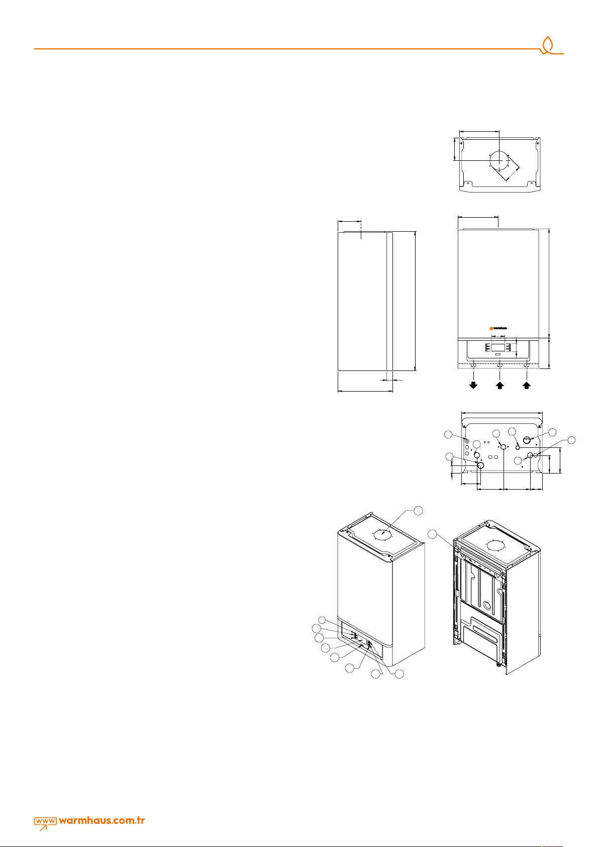
2.1.4. Dimensions and
Connections
distance 1.0 mt between the
heating device and the building
material containing combustible
material even the maximum
allowable temperature value of 85
° C in the rated heat capacity of
the appliance is not exceeded.
2.1.3. Mounting of the Boiler to Wall and Selection of Installation
Place
• Mounting of the boiler to wall must be checked and ensured to be
stable and safe.
• The hanger plate and connection screws supplied with the boiler
shall be mounted on a filled or semi-filled brick wall in accordance
with the installation scheme, and shall not be used for other
purposes.
• In case any different materials are used for mounting, the warranty
of the boiler shall be terminated.
• If the wall to which the boiler is to be mounter is not brick, strength
of the support system shall be checked.
• The boiler shall be mounted on a fire resistant wall.
• The boiler should be mounted so as the height of the hanger plate
to be between 1,8-2,2 mm from the ground.
• The boiler shall be mounted with gaps as minimum 30 cm above
the ground, minimum 5 cm from both sides and minimum 90 cm
from the front side where the installation area is limited, for allowing
easy intervention of the service technician.
• The boiler shall not be installed in areas which contain or may
contain explosives, flammables and acid vapors.
• It shall not be installed next to or above ovens, cookers, radiators or
heaters.
• Hermetic boilers can also be installed in cabinets, provided that
minimum 5 cm from each side is left.
• If the boiler is to be mounted over the kitchen countertop or
kitchen set, there shall be a minimum 50 cm distance under the
boiler.
• Due to possibility of water draining from the Safety Valve of the
boiler after mounting, the outlet shall be connected to the drainage
line. If this is not possible; do not place electronic appliances, and
tools, parts and materials which may breakdown, be deformed or
form rust.
• Any furniture should not be placed under the boiler due to the
reasons specified above.
• Make sure that there are no liquids or inflammable materials in the
immediate vicinity of the boiler.
9
10
11
12
13
16
Figure 6 Viwa 50 / Viwa 65 boiler dimensions and connections
Warmhaus Viwa 50 / 65
1) 230 V AC Main Power Supply
2) Manometer
3) Safety Valve Drainage Line
4) Gas Inlet Line
5) Heating Supply Line
6) Heating Return Line
7) Condensate Drainage Line
8) Sediment-Air Separator Discharge
9) Heating/Domestic Hot Water MODE
Button
10) Heating Temperature Increasing
Setting Button,
17
18
1415
11) Heating Temperature Reducing
Setting Button
12) LCD Display
13) Service Port
14) RESET Button
15) Domestic Hot Water Temperature
Increasing Setting Button
16) Domestic Hot Water Temperature
Reducing Setting Button
17) Exhaust gas/Flue outlet
18) Hanger plate
7
2.1.5. Natural Gas Connection (Appliance Category I2H)
The boilers are designed to run on methane (G20) gas. Gas supply
pipes shall be equal to or larger than 3/4"G boiler fittings. Prior to
making the gas connection, a thorough internal cleaning shall be
carried out to all fuel supply installation pipe furnishings as possible
wastes may distort smooth operation and reliability of the boiler.
Ensure that the gas supplied by the mains line is of the type prescribed
for the boiler (refer to the label on the boiler).
Also, in case of reduced pressure, the network dynamic pressure
(methane or LPG) used for supplying the combi should be carefully
controlled and will impact the boiler strength. Ensure that gas valve
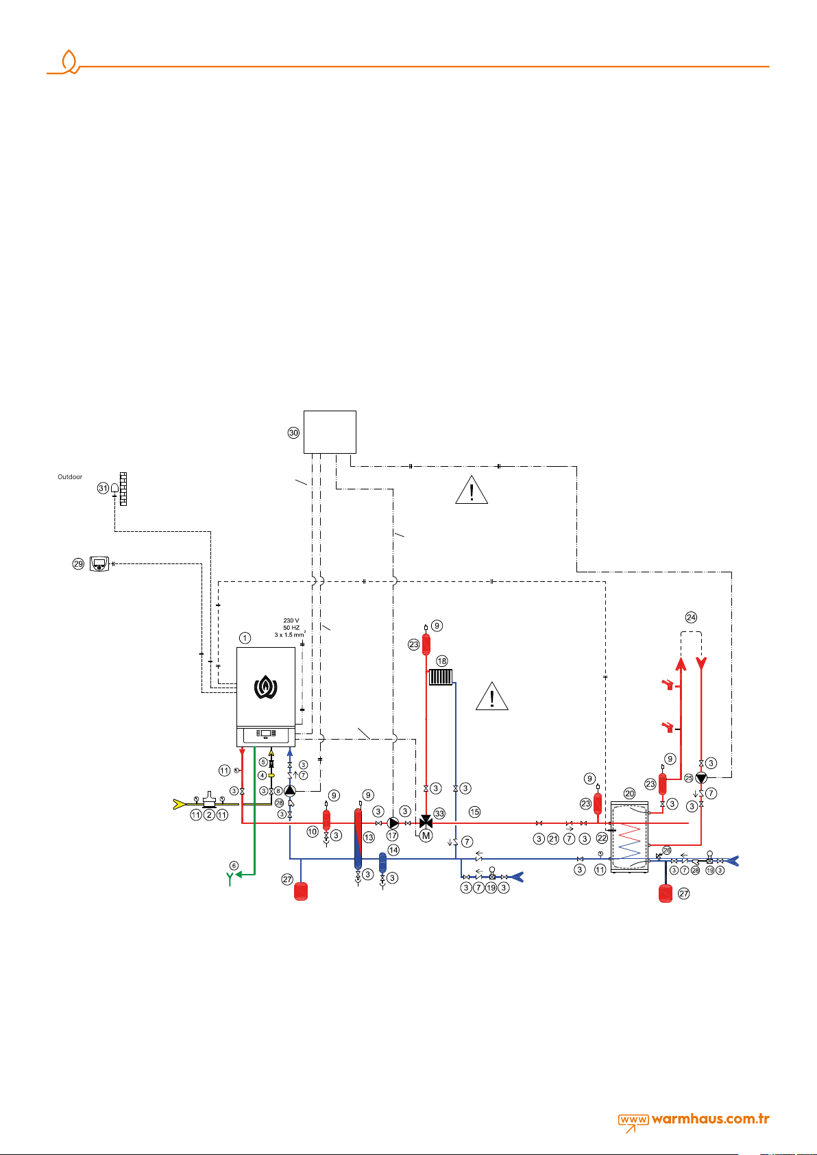
SAMPLE INSTALLATION SCHEME
Sngle Boler Scheme
Main
Electric
Panel
Boiler Pump
Outdoor Sensor
2
2 x 1.0 mm
Panel - Relay
Connection
3 x 1.0 mm
2
connection is correct. Flammable gas supply pipe should be able to
supply correct adequate gas amount to the boiler when the boiler is
at full power and be projected and sized according to force and local
gas company specification and instructions in order to guarantee the
appliance efficiency. Connection system shall comply with the legislation
in force.
2.1.6. Flammable Gas Quality
The boiler is designed to be used with pure fuel not containing any
foreign substances; therefore, required filter systems must be available in
the gas supply line (for ensuring purification of the fuel).
Recirculation Pump
The recirculation pump
will not be managed
by Boiler. It will be
managed by the main
electric panel.
System Pump Boiler Panel
Relay Connection
1. Zone + Storage Tank
Timer / Room Thermostad
Timer / Room Thermostad
2 x 1.0 mm
GAS
PIPELINE
2
FLUE
Boiler Pump
3 x 1.0 mm
3-Way Motorized
Valve Line
3 x 1.0 mm
Pump Cable
2
3 x 1.0 mm
Boiler Sensor
2
2 x 1.0 mm
2
In this electric scheme,
the boiler pump and
the system pump will be
managed via main electric
2
panel contactor.
RECIRCULATION CIRCUIT
COLD WATER
COLD WATER
INSTALLATION EQUIPMENT
1. Boler
2. Gas Safety Solenod Valve
3. Ball Valve
4. Gas Flter
5. Vbraton Isolator
6. Condensate Water Sphon
and Dranage Lne
Figure 7 Viwa 50-65 Single Boiler with 1 High Temperature Zone + Hot Water Storage Tank System Scheme Example.
8
7. Check-Valve
8. Boler (Return) Pump
9. Automatc Ar Vent
1O. Sedment-Drt-Ar Separator
11. Manometer
13. Hydraulc Separator
14. Sedment-Drt-Separator
17. Heatng System Pump
18. Heatng System
19. Pressure Reducer
20. Hot Water Storage Tank
22. Hot Water Storage Tank Sensor
23. Ar Separator
24. Hot Water Storage Tank
Recrculaton Crcut
25. Recrculaton Pump
26. Safety valve
27. Vessel Tank
28. Flter
29. Tmer / Room Thermostat
30. Man Electrc Panel
31. Outsde Sensor
2.1.7. Heating and Domestic Hot Water Installations
Radiator and ground heating installation shall be configured in
accordance with technical specifications of the TSE (Turkish Standards
Institution) and MMO (Chamber of Mechanical Engineers), and
according to the heat loss calculation. Radiator type and amount and
ground heating installation pipe amount shall comply with the heat loss
calculation.
• The design pressure strength of the heating installation shall be
minimum 6 bar.
• If the mains pressure is more than 6.5 bar, a pressure reducer must
be fitted.
• It is recommended to construct the radiator installation as double
line and without using bends and joints as much as possible.
• Strainer filter shall be installed in heating return and tap water (city
network) intake line if a boiler is to be used.
• An additional expansion tank with 50 liters capacity shall be used
depending upon the volumetric capacity of the heating water of the
heating circuit (closed circuit) and working temperature.
• If room thermostat and thermostatic radiator valve are to be used
together; thermostatic valve shall not be installed in radiators in the
place where room thermostat is present.
• Cross connection must be made for efficient functioning in radiators
longer than 1,5 m.
• Covers shall be used for radiator and domestic hot water wall
passages and fixed with wall clamps to prevent expansions due to
heating.
• An external boiler shall be fitted to the boiler for supply of domestic
hot water. In case of using domestic water boiler, the three-way
valve and boiler sensor within the product accessories.
• The heating installation must be washed and cleared off dirt before
filling!
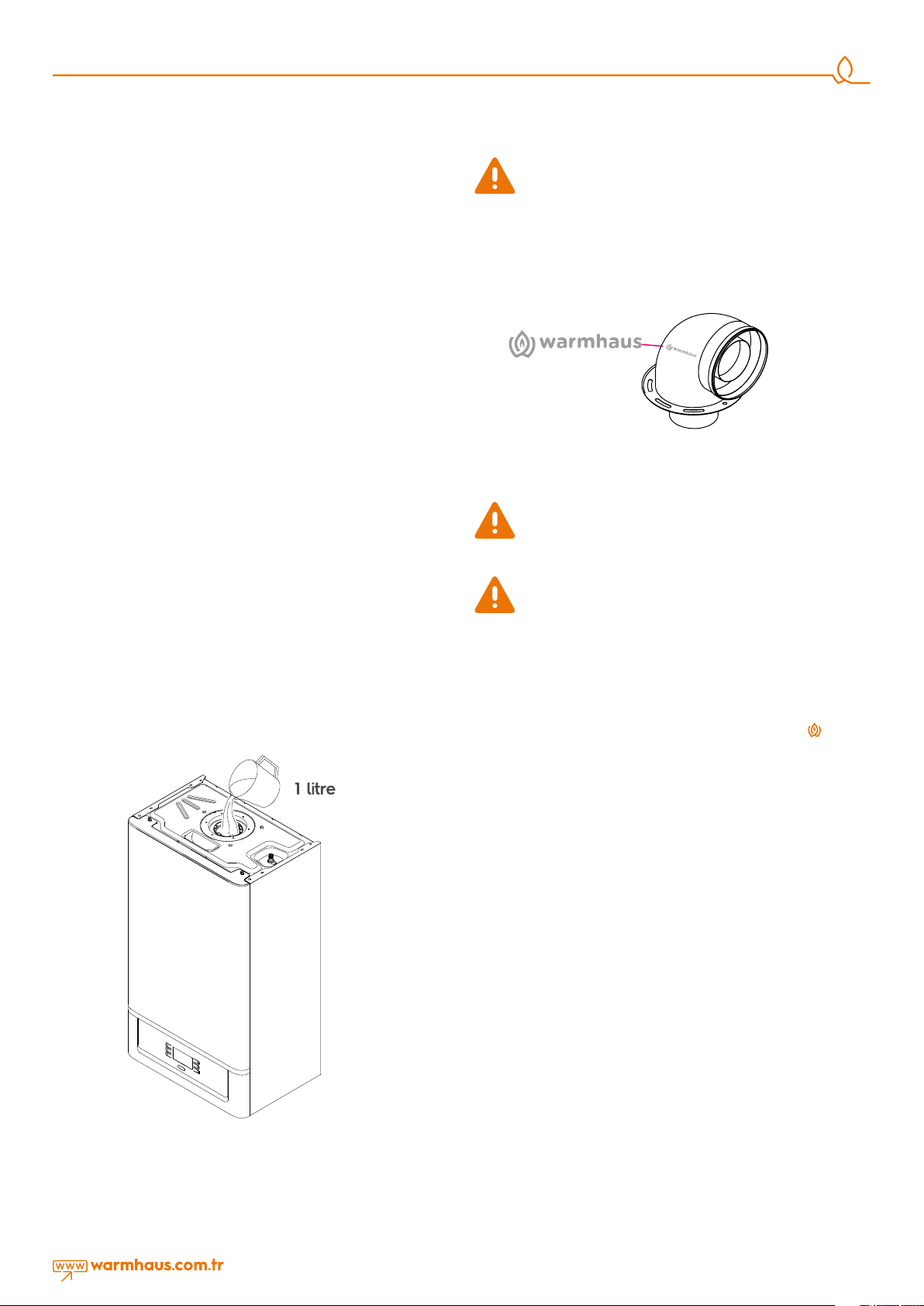
Leak-tightness of the drainage connection of the condensation
line shall be ensured. However, pour approximately 1-liter
water into the internal flue prior to fitting the flue bend of the
flusher in the boiler against the gas leak risk during start-up. Thus,
exhaust gas leakage will be prevented thanks to the water in the
flusher.
Slope of the condensate water hose and line shall always be
downwards
Figure 9 There is a Warmhaus logo on the flue bend.
2.1.9. Exhaust Gas Flue Pipe Set and Accessories Connection
Flue accessory sets to be used in exhaust gas installation of
hermetic boilers shall be original Warmhaus flue sets and they
shall be used by observing measurements and restrictions
given in installation instructions.
In case of using exhaust gas pipe and/or accessories other
than Warmhaus original exhaust gas flue pipes and
accessories, boiler shall not be commissioned by the
Authorized Service and thus, no warranty is provided!
2.1.8. Filling the flusher for Condensation Line
After the wall mounting operation of condensing boiler, electrical
connections, radiator lines, hot tap water connections and
condensation water drainage line are completed, condensation flusher
shall be filled with water (Figure 8).
The boiler shall only be installed with original Warmhaus air suction and
exhaust gas discharge device made of plastic material.
Plastic channels cannot be installed without suitable protection against
UV and weather conditions to distances over 40 cm and outsides.
Every pipe is defined with an explanatory and discriminative
Warmhaus mark mentioned in remarks.
IMPORTANT
When carrying out commissioning of the boiler, you are highly
recommended to perform the following checks:
- Make sure that there are no liquids or inflammable materials in the
immediate vicinity of the boiler.
- Make sure that the electrical connections have been made correctly
and that the earth wire is connected to a good earthing system.
- Open the gas valve and check the soundness of the connections,
including that of the burner to fan and burner hood to heat
exchanger
- Make sure that the boiler is set for operation for the type of gas
supplied.
- Check that the flue pipe for the outlet of the products of the
combustion is unobstructed and has been properly installed.
- Make sure that any shutoff valves are open.
- Make sure that the system is charged with water and is thoroughly
vented.
- Check that the circulating pump is not jammed.
- Purge the system, bleeding off the air present in the gas pipe by
operating the pressure relief valve on the gas valve inlet.
Figure 8 Filling the condensation flusher
9
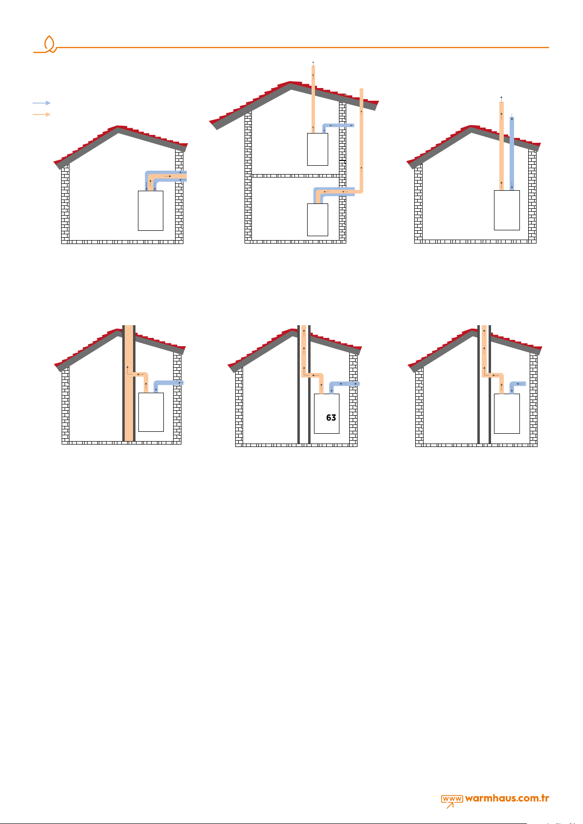
Ar
Exhaust Gas
C
53
C13
Dscharge wth homocentrc flue connecton
Figure 10 Hermetic (Concentric) and Flue
(Split-Flue type
C83
Dscharge to buldng chmney and fresh
ar ntake wth splt flue connecton
For room sealed applances of the type C8 bolers
a) overheat combuston products temperature; < 105 C°
b) CO2-content; 9.00 % ( tolerance +%0,5 / -0,5 % )
c) characterstcs of the chmney to whch the
boler may be connected, accordng to fg 13.
d) condensate flow nto the applance s not allowed.
Figure 13 Hermetic vertical split flue connection.
C
53
Exhaust gas dscharge and fresh ar ntake
wth concentrc flue kt and splt flue kts
For room sealed applances of the type C5 bolers
Attenton: The termnals for the supply of combuston
ar and for the evacuaton of combuston products
shall not be nstalled on opposte walls of the buldng.
Figure 11 Hermetic concentric and vertical split
flue connection.
C
Exhaust gas discharge through the building chimney and fresh
intake from outside with split flue sets
For room sealed appliances of the type C6 boilers
overheat combustion products temperature for flue; < 105 °C
CO
content at nominal operating conditions; 9.00 % (tolerance
2
+%0,5 / -0,5 % ) maximum allowable draught and maximum
allowable pressure dierence between combustion air inlet and
flue gas outlet (including wind pressures); 120 Pa. characteristics
and the applications of the duct system to which the boiler
can be connected; condensate flow into the appliance is not
allowed. Maximum allowable temperature of combustion air;
40 C° maximum allowable recirculation rate of 10 % under wind
conditions.
Attention: The terminals for the supply of combustion air and for
the evacuation of combustion products shall not be installed on
opposite walls of the building.
Figure 14 Building chimney connection with hermetic split flue
C33
Exhaust Gas Dscharge Fresh Ar
Intake wth Splt Flue Sets
Figure 12 Vertical Type Hermetic Use with
Split Flue Set
B
23
Exhaust gas dscharge through the
buldng chmney and fresh ntake
from outsde wth splt flue sets
Figure 15 Use with split flue set
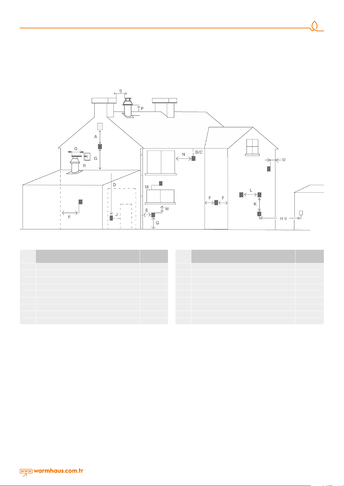
2.1.10. Peripheral Distances of the Flue Outlet Connections
For positioning of the flue set outlet pipe, see Figure 16. The flue shall
be installed in accordance with the national and local regulations.
No part of the outlet pipe or connections shall be blocked. If the
outlet pipe passes1000 mm nearby of a plastic or painted groove or
500 mm of painted fringes, an aluminum shield with at least 1000mm
length shall be placed below the groove or fringe. Outlet pipe shall
be at least 2 m over surfaces within reach by individuals. Under certain
weather conditions, outlet pipe may emit water vapor; installation shall
not be performed at places where this vapor may cause discomfort.
Exhaust gases shall be prevented from entering flue ventilation spaces.
Flue system of combi may be installed from inside the room without
requiring intervention from the external wall. For that reason, an
enclosure shall be installed in the wall for lining the internal surface of
channel wherein the outlet pipe passes through the wall, particularly
for thick walls.
10
2.1.11. Installation with (Ø80/125 mm) horizontal homocentric flue
sets Connection of (Ø80/125 mm) horizontal homocentric flue set
to the boiler
Since your boiler is a hermetic model, it takes the used air from outside and
discharges exhaust gases created as the result of burning through the same
flue group. In order to prevent emission of extremely harmful exhaust gases,
flue usage and installation is very important, therefore warnings should be
taken into consideration when flue connections are being performed.
• Carry out required flue selection for the external flue connection. If
the standard flue set is not adequate, please select most suitable
components from our list of connection accessories considering
warnings given in our user guide.
Select the most suitable components by also considering our
warnings.
• Fix the flange under the Bend piece (1) by using the Flange Bolt (10)
Flange Connection Screws (11) to holes on the boiler.
(10) secure it with Flange Connection Screws (11) onto the holes on
the boiler.
• 2 impermeability bolts within the hermetic flue set (2) are placed
into internal pipe slots at both ends of the 90° Bend.
• Place the exterior wall (EPDM) bolt into the flue terminal as seen in
Figure 11a for grouping the flue outlet terminal.
After placing the flue outlet terminal through exterior of wall and the
previously drilled hole, fix the Interior Wall Connection Bolt (7) into the flue
terminal. Place the other end of EPDM connection bolt installed on 90°
flue bend of your boiler to the flue outlet. Ensure that sealings are placed
properly:
Figure 16 Environmental locations of flue
Flue Location
A
Under a window 300 mm.
B
Under water groove 75 mm.
C
Under fringes 200 mm.
W
Under balcony 200 mm.
E
To vertical water discharge pipes 150 mm.
F
Interior or exterior corners 300 mm.
G
On the ground, roof or balcony level 300 mm.
H(*)
On another wall corresponding to the flue 600 mm.
S
To another flue 1200 mm.
(*) Not recommended for C5 and C6
VENTILATION
“Viwa 50 -65” boilers an be installed in boiler rooms whose size and
requirements meet current regulations. The following is provide for your
guidance only, and assumes the ventilation air is taken directly from
outside.
The sizes of the vents may need to be increased inrespect of other
appliances installed in the same area, and seasonal use. Take care that
the position of low level vents would not subject to adverse weather
conditions, ie flooding. Ventilation requirements for Viwa 50 -65 boilers
and cascade systems. BS6644 has a requirement that the temperatures
in a room or compartment do not exceed certain levels:
- +25°C at floor level (0-100 mm)
- +32°C at mid level (1.5 m above the floor level)
- +40°C at ceiling level (0-100 mm from ceiling)
When installed as a class B appliance (open flued, not roomed sealed).
Installed in a room High level (within 15% of the room height from
ceiling) - 2 cm²/kW of net heat input
Minimum
Distance
Flue Location
J
To a door other than garage wall 1200 mm.
R
To another flue from the same wall (vertical) 1500 mm.
Q
To another flue from the same wall (horizontal) 300 mm.
M
On another window/manhole 300 mm.
N
On another window/manhole horizontally 300 mm.
P
On the roof level 300 mm.
F
To an adjacent wall 300 mm.
I(*)
To the window on adjacent wall 1000 mm.
L
To another flue 600 mm.
Low level (low as possible within 1 meter from floor natural gas ) - 4
cm²/kW of net heat input a single Viwa 50 (46.88 KW net input) boiler
would require 100 cm² at high level and 200 cm² at low level.
Installed in a compartment or enclosure High level (within 15% of the
room height from ceiling) - 5 cm²/kW of net heat input Low level (low
as possible within 1 meter from floor natural gas) - 10cm²/kW of net
heat input.
A single Viwa 50 (46.88 KW net input) boiler would require 250 cm² at
high level and 500 cm² at low level.
When installed as a class C appliance (room sealed). Installed in a
room High level (within 15% of the room height from ceiling) - 2 cm²/
kW of net heat input Low level (low as possible within 1 meter from
floor natural gas) - 2 cm²/kW of net heat input A single Viwa 50 (46.88
kW net input) boiler would require 100 cm² at high level and 100 cm²
at low level.
Minimum
Distance
11
 Loading...