

Warmhaus VIWA 90, VIWA 115, VIWA 125, VIWA 150 Installation And User Manual

VIWA 90
VIWA 115
VIWA 125
VIWA 150
WALL MOUNTED CONDENSING BOILERS
INSTALLATION AND USER MANUAL
Viwa 90
Viwa 115
Viwa 125
Viwa 150

CONDITIONS
1. DEAR WARMHAUS
CUSTOMER
1.1. GENERAL WARNING
1.2. GENERAL WARRANTY CONDITIONS
1.3. GAS LEAKS
2. INSTALLATION PERSONNEL
SECTION
2.1. SAFE HANDLING
2.2. CONTENTS OF PACKAGE
2.2.1. Sizes and Connections
2.3. MOUNTING RULES FOR BOILER
2.3.1. General Rules for Places for Mounting
The Boiler
2.3.2. Places Where Hermetic Boilers Cannot
Be Mounted
2.3.3. Wall Mounting of Boiler and Selection
of Mounting Location
2.3.4. Quick Reference Guide for Air Supply,
Ventilation and Chimney Terminal
Positioning; BS 6644: 2011, IGE / UP /
10 (ed4) 2014 & BS 5440-1: 2008, BS
5440-2: 2009
2.4. NATURAL GAS CONNECTION
DEVICE CATEGORY I
2.4.1. Flammable Gas Quality
2.5. HEATER AND HOT DOMESTIC WATER
INSTALLATIONS
2.6. FILLING THE SIPHON FOR
CONDENSATION LINE
2.7. CONNECTION OF WASTE
GAS CHIMNEY PIPE SET AND
ACCESSORIES
2.7.1. Environmental Distances of Chimney
Outlet Connections
2.7.2. Connection of (Ø100/150 mm)
Horizontal Concentric Chimney Set
and Mounting Horizontal Concentric
Chimney Set to The Boiler
2.7.3. Mounting with Vertical Concentric
Chimney Sets
2.7.4. Mounting with Concentric Chimney
Sets in The Attic
2H
2.8. MOUNTING TO PARTIALLY
PROTECTED OUTER SPACES
2.9. ELECTRIC CONNECTIONS
2.10. OPTIONAL CONTROLS ROOM
THERMOSTAT, EXTERIOR
TEMPERATURE SENSOR AND OTHER
2.11. MOUNTING RULES FOR HYDRAULIC
INSTALLATION
2.11.1. Structure of Heating Water
2.11.2. Filling / Emptying Heating System
2.11.3. Discharge of Condensing Water
2.11.4. Circulation Pump (Optional)
2.11.5. Controls For The First Operation of
The Boiler
2.12. REQUIRED INSTALLATION ELEMENTS
FOR BOILER AND HEATING SYSTEM
OPERATION
2.12.1. Parts of Boiler
3. FOR USERS
3.1. GENERAL WARNING FOR USER
3.1.1. Use of Boiler
3.2. SELECTION OF SWITCHING ON
OFF STANDBY AND SUMMER
WINTER MODES
3.2.1. Positions of Switching On / Off /
Summer and Winter
3.2.2. Resetting the Boiler (Re-operate)
3.2.3. Operating in Winter Position
3.2.4. Operating in Summer Position (if a
boiler is connected)
3.2.5. Use with Room Thermostat (Optional)
3.2.6. Use of Exterior Temperature Sensor
(Optional)
3.2.7. Customization of Boiler Features
3.3. RESTORING FAULTS AND FAILURES
3.3.1. Failure Codes Table
3.4. SUGGESTIONS FOR USING BOILER
ECONOMICALLY
3.5. POINTS TO CONSIDER BY USERS
FOR WARRANTY CONDITIONS
3
1. DEAR WARMHAUS CUSTOMER
We congratulate and thank you for choosing Warmhaus wall mounter
boiler which shall provide you heating and domestic hot water
comfort for years. State-of-art Warmhaus boilers, being manufactured
in compliance with standards of the European Union are also
exported to many countries. You can utilize our Authorized Technical
Service network with professional competence certification for any
ordinary maintenance needs of this product produced meticulously
with hard work. Our authorized services assure sustaining performance
of the device as they shall always provide original spare part services.
Please read this manual thoroughly to use your boiler economically,
comfortably and efficiently, and store to refer when needed.
It is recommended for efficient use to have assembly done by an
authorized dealer approved by the local gas authority and which has
the competence and experience for assembly.
1.1. GENERAL WARNINGS
This manual is an integral part of the product, and must be delivered
to the new user in case of handover of the appliance. The manual
shall be preserved properly and kept in the way to be referred as it
contains significant information about use as well as installation of the
appliance.
Heating and Domestic Hot Water installations shall be
projected and implemented a competent and approved
engineering company meeting the criteria prescribed by laws,
by observing the current legislation in force.
Installation and maintenance shall be carried out by the
competent personnel having sufficient knowledge in the
installation industry and professional competence certification
in accordance with the legislation in force and in line with the
directions of the manufacturer. Hazards which may cause injury of
persons, other living beings (animals, plants) and damage to goods
may be caused by wrong installation, for which the manufacturer
cannot be held responsible.
Natural gas installation project; shall be carried out by one
of the dealers authorized by your local gas authority.
The manufacturer may not be held responsible for any
faults caused by noncompliance to the legislation and
standards in force and information provided in this manual
(and information and instructions provided by the manufacturer in
any case), within or out of the scope of the contract, and this also
constitute reason for termination of warranty of the appliance.
Only Warmhaus Authorized Service is authorized to carry out
electrical connection of the boiler and to energize the boiler.
In case of any material, design or installation faults occurred within
the warranty period, maintenance and operation shall be carried out
without any charge of labor or spare parts.
(Also see: 3.5 MATTERS TO PAY ATTENTION FOR GUARANTEE
CONDITIONS)
This appliance should only be used for its designed intended
purposes (to be used in closed-circuit heater installation and
production of open circuit domestic hot water production).
. All kinds of other uses are not suitable as well as may create a
potential danger.
Manufacturer shall not be responsible for damages
occurring due to interventions, false installation and initial
starting performed by unauthorized persons and warranty
scope shall be void. As the Combi is an appliance having heating
system, domestic hot water, natural gas/LPG and electrical
connections, do not make and have any interventions made without
the authorized service
appliance maintenance operations should be performed by
the authorized and competent technical personnel, and
Warmhause Authorized Technical Service Centers constitute
assurance for quality. WARMHAUS is not responsible for damages
arising from repairs, part replacements and maintenance performed by
third persons and companies and combi remains out of the warranty
scope under such conditions.
Attention! Please note & read the warning and informations on the
boiler. Incorrect operation of the boiler can cause significant damage.
For Warmhaus wall-mounted boilers; commissioning, adjustment,
maintenance and cleaning must only be carried out by a specialist OR
approved service by Warmhaus!
When faults occur in the heating system, the plant must be stopped
and damaged parts should only be replaced by an authorized
workshop.
The accessories used must correspond to the technical rules and the
relevant parts must be approved by the manufacturer in connection
with the Warmhaus wall-mounted boiler.
Only APPROVED & ORIGINAL spare parts should be used.
Bolts sealed with paint strictly forbidden to open!
The boiler must not be used by children younger 8 years or
invalid persons without supervision.
These seals provide evidence that the replacement of bolts required
for safe operation. If the seals are damaged, the guarantee of the
device will come to an end!
1.2. TERMS AND CONDITIONS OF WARRANTY
This appliance has been manufactured to be installed in the
country specified on its technical registration label. Installing
the appliance in any other country than those specified on
the plate may cause damage or injury to persons, animals and goods.
WARMHAUS declares that Viwa 90, Viwa 115, Viwa 125 & Viwa 150
boilers comply with the essential requirements of the following
directives:
- Gas Appliances Regulation (EU) 2016/426
- Boiler Efficiency Directive 92/42/EEC
- Electromagnetic Compatibility Directive 2014/30/UE
- Low Voltage Directive 2014/35/UE
- Ecodesign Directive 2009/125/EC
- Regulation (EU) N. 813/2013 - 811/2013
Manufacturer: Warmhaus Isıtma ve Soğutma Sistemleri Tic. A.Ş. Bursa
Organize Sanayi Bölgesi Park Cad. No:10 16140 Nilüfer-Bursa / Turkey
WARMHAUS A.Ş. reserves the right to make all kinds of technical and
commercial modifications without notice, and disclaims any liabilities
arising out of printing and spelling mistakes.
4
WARMHAUS
WARMHAUS
90 kW
1015 18
115 kW
1015 18
125 kW
1015 18
150 kW
1015 18
IMPORTANT INFORMATION
It is a statutory requirement that all gas appliances are installed by competent persons, in accordance with the gas safety (installation and use)
regulations (current edition). The manufacturer's instructions must not be taken as overriding any statutory requirements, and failure to comply
with these regulations may lead to prosecution. No modifications to the appliance should be made unless they are fully approved by the
manufacturer. Gas leaks: do not operate any electrical switch, or use a naked flame. Turn off the gas supply and ventilate the area by opening
doors and windows contact the gas emergency service
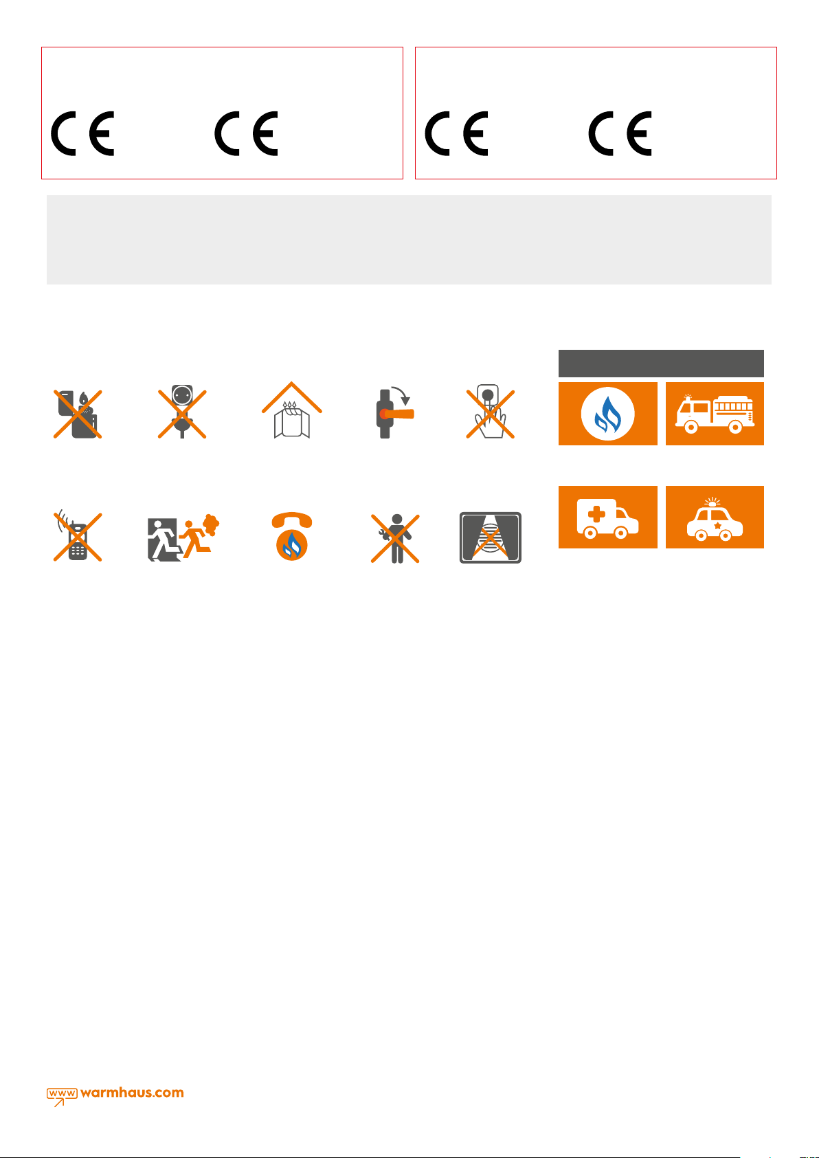
1.3. GAS LEAKS
NATURAL GAS EMERGENCY LINE
HOW TO ACT IN CASE OF DETECTING NATURAL GAS ODOR
IN EMERGENCY CASES
Do not use
lighter- matches
Do not turn on, off
or unplug the lamps
or other electrical
appliances.
Ventilate the
environment by
opening doors and
windows.
Close valves of
appliances operating with natural gas
and your gas meter
Do not use/let
anyone use the
doorbell.
NATURAL GAS
EMERGENCY
FIRE
DEPARTMENT
Do not use phones
in case of a natural
gas leakage. It may
create sparks.
Immediately evacu-
ate the place with
ga s od or.
Call the Natural Gas
Emergency Line from
your neighbor or ano-
ther suitable place.
Do not intervene the
installation Wait for
Gas Authorities Team
to arrive.
Never close culverts
ensuring discharge of
the gas from the en-
vironment in case of a
natural gas leakage.
AMBULANCE POLICE
INFORMATION: You can visit web sites of
local gas authorities and NATURAL GAS
EMERGENCY sections.
Advice: Please take note local emergency
phone numbers.
5
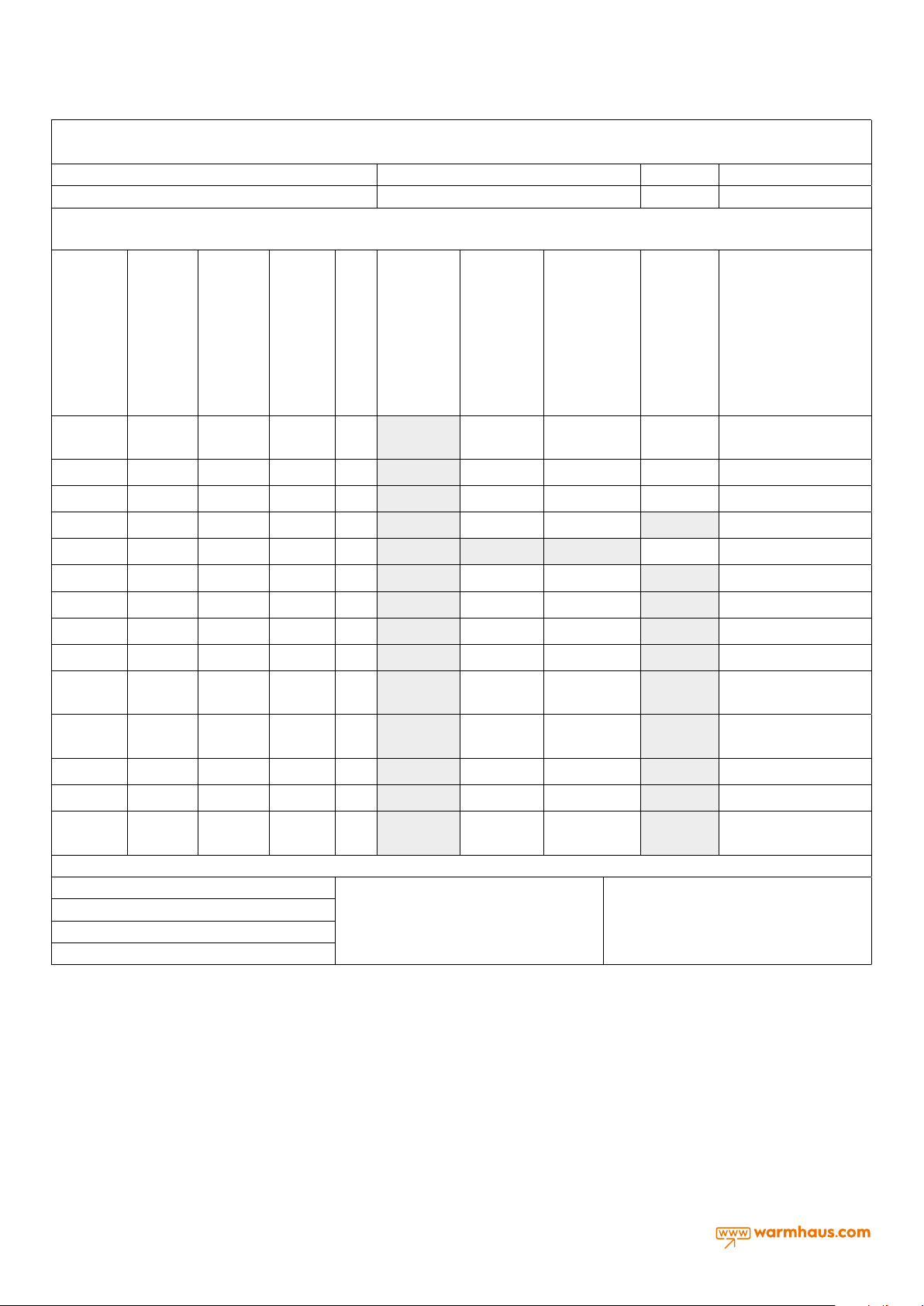
1.4 BOILER GAS CATEGORIES & REGIONS
Designation: Used gas types & Countries
Manufacturer Type Model / Technical Data Conformity Markings
Boiler Gas Categories & Regions Wall mounted type Warmhaus combis and boilers granted
Gas categories for Warmhaus boilers are implemented on the CE certificate given below by SZU Test / BRNO;- appliance categories according to direct destinations are determined in
accordance with EN 15502-1. According to-EN ISO 3166-1 destination countries;- millibar gas supply pressures, can be used for several gas groups if it is under normal pressure. They are
specified with numerical values and "mbar" unit.
Enerwa 24
Enerwa 2530
Document for
conformity
approved by
SZU test
YES I 2H Natural Gas 20 mbar G20 Not Approved Approved Approved Approved
YES I 2H Natural Gas 25 mbar G20 Not Approved Approved Approved Approved HU
YES I 2E Natural Gas 20 mbar G20 Not Approved Approved Approved Approved DE, LU, PL, RO
YES I 2E+ Natural Gas 20 mbar G20 Not Approved Approved Approved Not Approved BE, FR
YES I 2E(S) Natural Gas 20 mbar G20 Not Approved Not Approved Not Approved Approved BE
YES I 2E+ Natural Gas 25 mbar G25 Not Approved Approved Approved Not Approved BE, FR
Appliance
Categories
Gas Type
Gas Inlet
Supply
Pressures
Used
Gas
Lawa 24
Lawa Plus 24
Lawa 28
Lawa Plus 28
Priwa 24
Priwa Plus 24
Priwa 28
Priwa Plus 28
Priwa 33
Priwa Plus 33
Enerwa Plus 24
Enerwa Plus 2530
Enerwa 28
Enerwa 3035
Enerwa Plus 28
Enerwa Plus 3035
Enerwa 33
Enerwa 3540
Enerwa Plus 33
Enerwa Plus 3540
Viwa 50
Viwa 65
Viwa 90
Viwa 115
Viwa 125
Viwa 150
Countries of
Destination **
AT, BG, CH, CZ, DK, EE, ES, FI,
GB, GR, IE, IT, LT, LV, NO, PT, RO,
SE, SI, SK
YES I 2L Natural Gas 25 mbar G25 Not Approved Approved Approved Not Approved NL
YES I 2ELL Natural Gas 20 mbar G20 Not Approved Approved Approved Not Approved DE
YES I 2ELL Natural Gas 20 mbar G25 Not Approved Approved Approved Not Approved DE
YES II 2H3P Natural Gas 20 mbar G20 Not Approved Approved Approved Not Approved
YES II 2H3P Propane LPG 37 mbar G31 Not Approved Approved Approved Not Approved
YES II 2L3P Natural Gas 25 mbar G25 Not Approved Approved Approved Not Approved NL
YES II 2L3P Propane LPG 37 mbar G31 Not Approved Approved Approved Not Approved NL
YES I 3P Propane LPG 37 mbar G31 Not Approved Approved Approved Not Approved
EN ISO 3166-1: 2006, Codes for the representation of names of countries and their subdivisions - Part 1: Country codes (ISO 3166-1: 2006)
Prepared by: İsmail B.Taşdemir / R&D Mng.
Date of Publication: 18/4/2017
Rev. No: 2
Drw. No: WH.17.107
Table 1.1
Approval; revision was made with E-30-00300-18 GAR
certificate and CE-1015CT0615 product number. And
correction 02 Viwa 50 and 150 kW addition equivalent.
This document and the information contained herein
belong to Warmhaus Isıtma ve Soğutma Sistemleri San.
Tic. A.Ş. It shall not be transferred to any person not
authorized by Warmhaus Isıtma ve Soğutma Sistemleri
San. Tic. A.Ş. or copied or used howsoever by any third
persons without prior written approval.
CH, CZ, ES, FR, GB, GR, IE, RO,
CH, CZ, ES, FR, GB, GR, HR, IE,
BE, CH, CZ, ES, FR, GB, GR,
HR, IE, IT, LT, NL, PL, PT, RO,
SI, SK
IT, LT, PT, RO, SI, SK
SI, SK, TR
Table 1.2
6
GAS
G1"
G1 1/2"
G1 1/2"
2. INSTALLATION PERSONNEL
SECTION
2.1. SAFE HANDLING
This boiler may require 2 or more operatives to move it into its
installation site, remove it from its packaging and during movement into
its installation location. Manoeuvring the boiler may include the use of
a sack truck and involve lifting pushing and pulling.
Caution should be exercised during these operations. Operatives
should be knowledgeable in handling techniques when performing
these tasks and the following precautions should be considered:
– Grip the boiler at the base
– Be physically capable
– Use personal protective equipment as appropriate e.g. gloves, safety
footwear.
During all manoeuvres and handling actions, every attempt should be
made to ensure the following unless unavoidable and/or the weight is
light.
– Keep back straight
– Avoid twisting at the waist
– Always grip with the palm of the hand
– Keep load as close to the body as possible
– Always use assistance
WARNING
Caution should be exercised when performing any work on this
appliance.
– Protective gloves and safety glasses are recommended.
– Avoid direct contact with sharp edges.
– Avoid contact with any hot surfaces
NOTICE
Please be aware that due to the wet testing of the appliance, there
may some residual water in the hydraulic circuit.
– Protect any surfaces, carpets or floorings.
– Use a suitable container to catch any water that escape when
removing the protective caps from the connections.
INSTALLATION
The boiler must be installed in a fixed location, by qualified
engineers in compliance with all instructions contained in
this manual. Furthermore, the installation must be in accordance with
current standards and regulations.
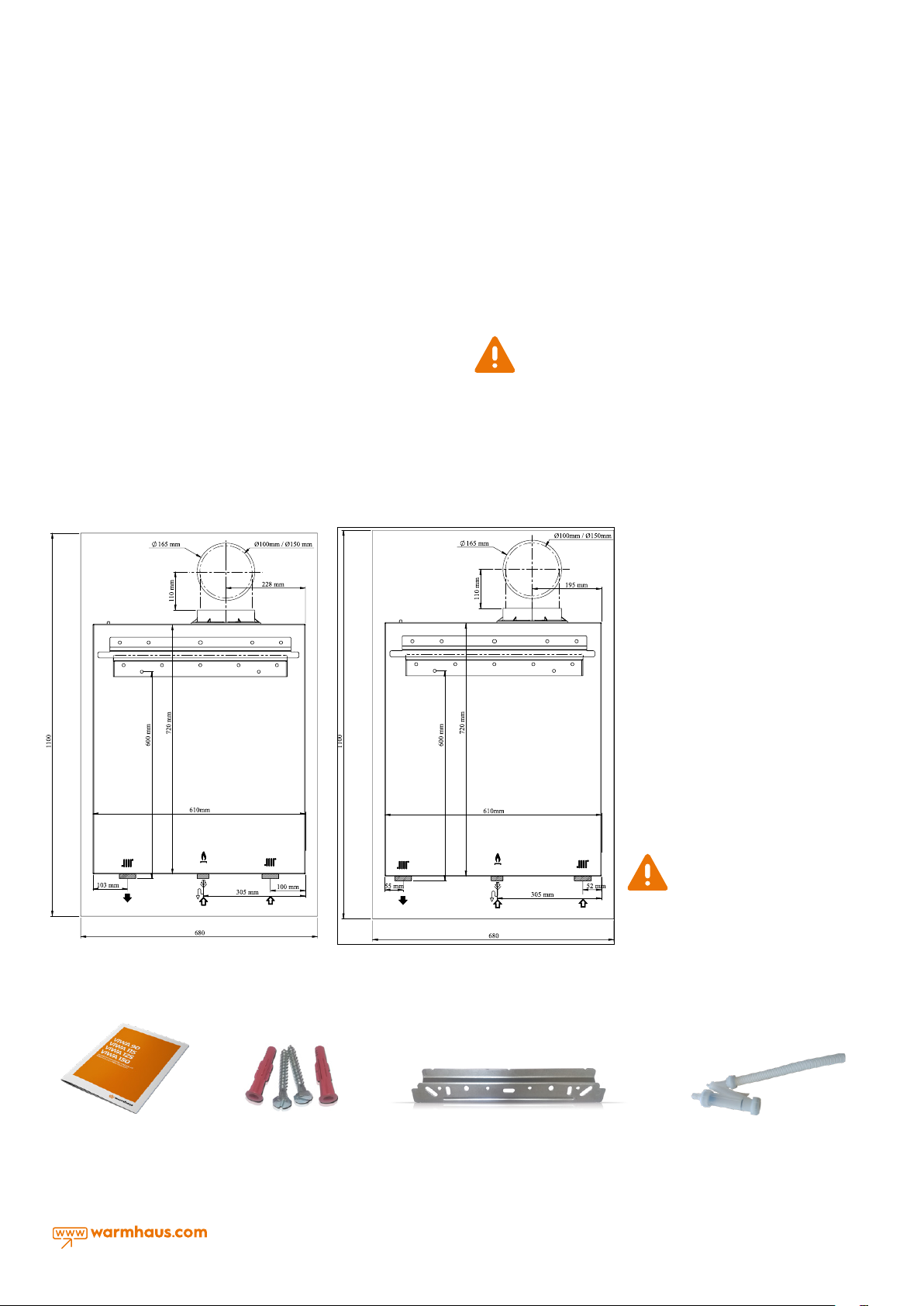
2.2. CONTENTS OF PACKAGE
There are the following materials in the boiler box. In the Viwa 90-150
boiler group, waste gas chimney sets are not supplied with the boiler
and must be ordered separately.
GAS
G1 1/2"
Figure 2.2 Mounting Template of Viwa 90 & Viwa 115
(Back view)
Figure 2.3 User manual
G1"
G1 1/2"
Accessories
Figure 2.1 Mounting Template of Viwa 125 & Viwa 150
(Back view)
Figure 2.5 Rod-fastening plateFigure 2.4 Connection
I. Mounting Template (Figure 2.1 and 2.2)
II. User Manual (Figure 2.3)
III. Connection Accessories (Figure 2.4)
a. 1 Throttle Screw (mounted on the
chimney outlet.)
b. 2 Hanger Screws
c. 2 Dowels
IV. Rod-fastening plate (Figure 2.5)
V. Condensing Siphon (Figure 2.6)
Do not leave the packaging material (plastic bag, nylon, etc.) in a
place where children can reach it,
in order not to create a health hazard.
Figure 2.6 Siphon part for discharging
condensing water
7
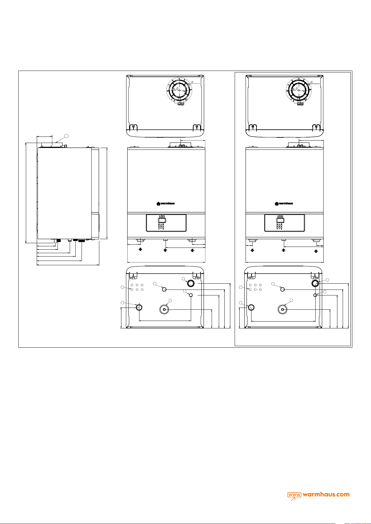
2.2.1. Sizes and Connections
790
120
148
164
261
305
330
498
153,4
103,4
18
720
102
CH Flow
G1 1/2"
Gas İnlet
G 1"
615
322
195
CH Return
G1 1/2"
102
54
CH Flow
G1 1/2"
Gas İnlet
G 1"
615
103,4
322
153,4
195
CH Return
G1 1/2"
54
Warmhaus Vwa 125 / Vwa 150
1) Heater Return Line
2) Sediment-Air Separator Discharge Line
6
3) Condensing Water Discharge Line
4) Gas Inlet Line
5) Heater Stream Line
5
6) Cable Outlets
7) Waste Gas Outlet Connection (Ø100mm)
8) Fresh Air Inlet Connection (Ø150 mm)
164
9) Fresh Air Measurement Point
10) Waste Gas Measurement Point
Figure 2.7 Boiler sizes and connections Viwa 90 / Viwa 115 Viwa 125 / Viwa 150
2.3. MOUNTING RULES FOR BOILER
2.3.1. General Rules for Places for Mounting The Boiler
There is no ventilation limitation for places where the hermetic (C
type) boiler is mounted (the devices can be mounted regardless of
the volume and ventilation form of the room). In addition, it can be
mounted in partially protected areas such as balconies and terraces
provided that it is in the protective cabin and necessary precautions
are taken against freezing in the installation water. However, the
installation requirements of the local gas company in the area to be
mounted must also be taken into consideration, so be careful about
the mounting locations for over a certain capacity!
The boiler should be mounted firmly on the building wall. A flexible
connection element must be used between the boiler and the gas
line. Flexure lengths to be used on A, B and C type devices shall not
exceed the permissible limits from local gas companies. The chimney
outlets of the hermetic boilers must be connected directly to the
outdoor with open air circulation. The gas outlet conditions of waste
gas installation of these devices should be in accordance with the
rules set out in TS 12514 standard (positions of the pipe outlets in
relation to various forms, vertical, horizontal minimum distances, crosssectional areas of the ducts if connected to ducts).
3
CONDANSATE
DRAIN
1
305
6
5
330
164
2
261
148
4
3
CONDANSATE
DRAIN
507
4
411
1
2
330
305
261
148
2.3.2. Places Where Hermetic Boiler Cannot Be Mounted
• To the stairwells of buildings
• To the common spaces of the buildings which are open to general
use, air wells and day spaces, to the attic, to the under the roof, to
emergency exit doors, and similar places such cellar, hall etc.
• To the yards between buildings
• To narrow eaves gaps
• On chimney walls,
• To closed balconies,
• To open balconies except for being in a cabin and permitted by
device company and local gas company),
• Underneath the protruding parts of the structure which prevent the
outler of waste gas,
• To places where can be exposed to direct wind pressure
• It is forbidden to mount hermetic boilers (type C) in openings that
provide fresh air to other units!
2.3.3. Wall Mounting of Boiler and Selection of Mounting Location
• It must be checked and guaranteed wall-mounting of boiler is sound
and safe.
8

Figure 2.8 Environmental locations of flue
Chimney Position
A
Under a window 300 mm.
B
Under water groove 75 mm. 75 mm.
C
Under fringes 20 mm. 200 mm.
W
Under balcony 200 mm.
E
To vertical water discharge pipes 150 mm.
F
To inside or outside corners 300 mm.
G
To ground, roof or balcony level 300 mm.
H (*)
To another wall corresponding to the wall 600 mm.
S
To another chimney 1200 mm.
J
From the garage wall to another door 1200 mm.
R
From same wall to another chimney (vertically) 1500 mm.
Q
From same wall to another chimney (horizontally) 300 mm.
M
On another window / culvert 300 mm.
N
Horizontally another window / culvert 300 mm.
P
To the roof level 300 mm.
F
To a neighbouring wall 300 mm.
I (*)
On the window on the neighbouring wall 1000 mm.
L
To another chimney 600 mm.
(*) Not recommended for C5 ve C6 !
• The hanger plate supplied as standard with the boiler shall be
mounted on a full or half-full brick wall in accordance with the
connection screws and mounting template in compliance with its
technique and shall not be used for any other purpose.
• If different materials are used for mounting, the boiler will be out of
warranty.
• If the wall to be mounted on is not a brick wall, the durableness of
the support system must first be checked.
• The boiler must be mounted on a fire-resistant wall.
Minimum
Distance
• It is recommended to mount the boiler between 1.8 - 2.2 m length
of hanger plate from the ground.
• In places where mounting area is limited, the boiler must be
mounted minimum 30 cm above the ground, with a space of
minimum 5 cm from the sides and 90cm from the front for easy
intervention of service technician.
• The boiler is not mounted in places with explosive, flammable
material and acid vapor.
• It is not mounted on sides of above cookers, ovens or heating
devices.
• Hermetic boilers can be mounted inside the furniture as well, but at
least 5 cm spacing should be left on their sides.
• It is advisable to connect the outlet of the boiler to the outlet line
by means of a transparent hose to prevent the possibility of water
coming from safety valve of boiler after mounting. If this is not
possible; do not put electronic devices, tools, parts and equipment
that can breakdown, rust, etc. under the boiler.
• Due to the above reasons, it is not recommended to put any
furniture under the boiler.
2.3.4. Air Supply, Ventilation and Flue Terminal Positioning Quick
Reference Guide for; BS 6644:2011, IGE/UP/10 (ed4) 2014 & BS
5440-1:2008, BS 5440-2:2009, BS6644:2011 Specification for the
Installation of gas-fired hot water boilers of rated inputs between
70 kW (net) and 1.8 MW (net) (2nd and 3rd family gases) & IGE/
UP/10 2014 Edition 4 Installation of Gas Appliances in Industrial
and Commercial Premises
For BS 6644 and IGE UP 10 Installations the ventilation openings might
need to be increased if the following air temperatures are exceeded.
(@15°C Ambient)
High-Level (100mm Below Ceiling Level) 40°C
Mid-level (1500mm Flow Floor Level) 32°C
Low-Level (100mm Above Floor Level) 25°C
As a guide, reduction of air temperature may be achieved by increasing
the inlet and outlet air supply by 0.15 m3/h or 0.2 cm2/kW of net heat
input per 0C of temperature reduction required.
9
Room Sealed Appliances Installed within an Enclosure (Natural ventilation requirements direct to Outside Air)
Grille Location
System Type
600m from any obstruction
High Level (Free Area/kW) 5 cm
Low Level (Free Area/kW) 5 cm
Heating &/or HWS
Operation < 50% during summer months
2
2
Heating &/or HWS
Operation > 50% < 75% during summer
months
2
6 cm
2
6 cm
Heating &/or HWS
Operation > 75% during summer months
2
7 cm
2
7 cm
Room Sealed Appliances Installed within an Enclosure (Natural ventilation requirements Via an internal Space)
Grille Location
600m from any obstruction
High Level (Free Area/kW) 10 cm
Low Level (Free Area/kW) 10 cm
System Type
Operation < 50% during summer months
Heating &/or HWS
2
2
Operation > 50% < 75% during summer
Heating &/or HWS
months
2
11 cm
2
11 cm
Operation > 75% during summer months
Heating &/or HWS
2
12 cm
2
12 cm
Room Sealed Appliances Installed within a Boiler Room / Heated Space (Natural ventilation requirements direct to Outside Air.)
Grille Location
600m from any obstruction
High Level (Free Area/kW) 2 cm
Low Level (Free Area/kW) 2 cm
System Type
Operation < 50% during summer months
Heating &/or HWS
2
2
Operation > 50% < 75% during summer
Heating &/or HWS
months
2
3 cm
2
3 cm
Operation > 75% during summer months
Heating &/or HWS
2
4 cm
2
4 cm
Max Operating Pressure < 100mbar, Room Air Change Rate >0.5/hour = No Additional Ventilation. If the air change rate is less than 0.5/hour them
the following must be applied.
Appliances without draught diverters with or without draught stabilisers
Grille Location
600m from any obstruction
High Level (Free Area/kW) 1.35 +/- 0.18 (m
Low Level (Free Area/kW) 2.6 (m
System Type
Operation < 50% during summer months
Heating &/or HWS
3
/h/kW) 1.35 +/- 0.18 (m3/h/kW) 1.35 +/- 0.18 (m3/h/kW)
3
/h/kW) 3.32 (m3/h/kW) 4.04 (m3/h/kW)
Operation > 50% < 75% during summer
Heating &/or HWS
Operation > 75% during summer months
months
Heating &/or HWS
VENTILATION
“Viwa 90 - 150” boilers an be installed in boiler rooms whose size and
requirements meet current regulations. The following is provide for your
guidance only, and assumes the ventilation air is taken directly from
outside. The sizes of the vents may need to be increased inrespect
of other appliances installed in the same area, and seasonal use. Take
care that the position of low level vents would not subject to adverse
weather conditions, ie flooding.
Ventilation requirements for Viwa 90 -150 boilers and cascade systems.
BS6644 has a requirement that the temperatures in a room or
compartment do not exceed certain levels:
- +25 °C at floor level (0-100 mm)
- +32 °C at mid level (1.5 m above the floor level)
- +40 °C at ceiling level (0-100mm from ceiling)
When installed as a class B appliance (open flued, not roomed sealed).
Installed in a room High level (within 15% of the room height from
ceiling) - 2 cm²/kW of net heat input Low level (low as possible within
1 metre from floor natural gas ) – 4 cm²/kW of net heat input A single
Viwa 125 (116 kW net input) boiler would require 232 cm² at high level
and 464 cm² at low level. Installed in a compartment or enclosure
High level (within 15% of the room height from ceiling) - 5 cm²/kW of
net heat input Low level (low as possible within 1 metre from floor
natural gas) –10 cm²/kW of net heat input. A single Viwa 125 (116 kW net
input) boiler would require 580 cm² at high level and 1160 cm² at low
level. When installed as a class C appliance (room sealed). Installed in
a room High level (within 15% of the room height from ceiling) - 2 cm²/
kW of net heat input Low level (low as possible within 1 metre from
floor natural gas) – 2 cm²/kW of net heat input A single Viwa 125 (116
kW net input) boiler would require 232 cm² at high level and 232 cm²
at low level.
2.4. NATURAL GAS CONNECTION DEVICE
CATEGORY I2H
Our boilers were manufactured to run with methane gas (G20).
Gas supply pipes must be equal to or greater than 3/4 "G boiler
connections. Before connecting the gas, a careful internal cleaning of
the pipe laying of the entire fuel supply installation must be carried
out, since possible waste will damage the best performance and
efficiency of the boiler. It must be checked that the gas distributed
from the main line is in the type stipulated for the boiler (see the label
on the boiler).
In addition, the network dynamic pressure (methane) to be used
in feeding the boiler and in case of it is inadequate, that may
affect the power of the boiler and cause difficulties for the user.
Make sure the gas valve connection is made correctly. The
flammable gas supply pipe must be designed and dimensioned
according to the current MMO and local gas company
specifications and instructions in order to ensure that the boiler is
capable of delivering sufficient gas to the burner while the boiler
is operating at maximum power and the device is efficient. The
connection system must comply with legal regulations.
2.4.1. Flammable Gas Quality
The boiler is designed to be used with pure fuel which does not
contain foreign substance in; for this reason it is absolutely necessary
to add the necessary filter systems in the gas supply line (in order to
ensure that the fuel is purified).
10
Resirculation pump
Outside Air Sensor
2 x 1.0 mm
Stroge Tank Pump
Stroge Tank
2
Sensor
2 x 1.0 mm
COLD
WATER
RESIRCULATION CIRCUIT
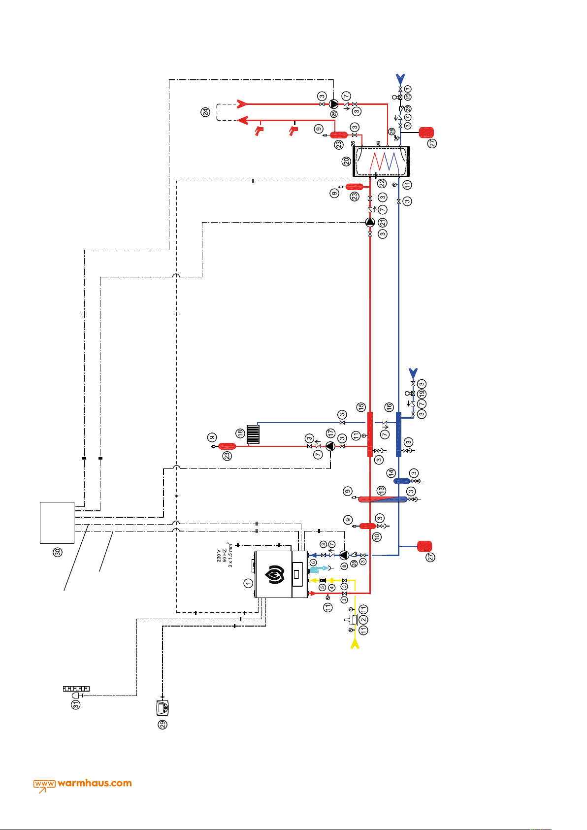
24. Hot Water Tank Recirculation Line
25. Recirculation Pump
26. Safety Valve
27. Expansion Tank
28. Filter
29. Timer/Room Thermostat
30. Boiler Electrical Panel
31. Outside Air Sensor
COLD
WATER
Collector
16. Heating System Return Water
17. Heating System Pump
18. Heating System
19. Pressure Reducer
20. Hot Water Tank
21. Hot Water Tank Pump
22. Hot Water Tank Sensor
23. Air Separator
Boiler
Electrical
Panel
2
Boiler panel and
Electrical Panel connection
for System Pump
3 x 1.0 mm
2
Boiler panel and
Electrical Panel relay connection
for System Pump
3 x 1.0 mm
Timer/Room
2
Thermostat
2 x 1.0 mm
2
System Pump
3 x 1.0 mm
2
Collector
8. Boiler (Return) Pump
9. Automatic Air Purge Valve
10. Sediment-Dirt-Air Separator
11. Manometer
12. Hydraulic Separator Sensor
13. Hydraulic Separator
14. Sediment-Dirt Separator
Pump
cable
3 x 1.0 mm
FLUE
15. Heating System Steam Water
Figure 2.9 A Radiator Circuit Viwa and A Hot Water Supply connection diagram with Viwa 90 / Viwa 150 boiler
Line
INSTALLATION EQUIPMENT
1. Boiler
2. Gas Safety Solenoid Valve
3. Ball Valve
4. Gas Filter
5. Vibration İsolator
6. Condensate Siphon and Drainage
7. Check Valve
GAS LINE
2
11
2.5. HEATER AND HOT DOMESTIC WATER
INSTALLATIONS
Radiator and floor heating installations should be performed according
to TSE and MMO technical specifications according to heat loss
calculation. The type and quantity of the radiator and the quantity of
piping of the heating installation must also be appropriate for the
calculation of heat loss.
• The heating installation must be installed at a pressure enduring at
least 6 bar.
• If the city pressure is higher than 6.5 bar, the pressure reducer must
be assembled.
• It is recommended that the heating installation be performed as
double or mobile line (at least) and avoiding the elbows and joints
as many as possible.
• A strainer filter must be definitely installed in return line of heater and
if a hot water tank will be used, in inlet line of domestic water (city).
• An additional expansion tank of at least 50 litres should be used
depending on the volume of the heating water and the working
temperature of the heating circuit (closed circuit).
• If room thermostat and thermostatic radiator valve will be used
together; the thermostatic valve should not be installed in radiators
in places where the room thermostatic available!
• Radiators longer than 1.5 m must be cross-connected for efficient
operation.
• Sheaths should be used in the passages of the heating and hot
water from the walls and they should be fixed with wall clamps so
as not to incline in the expansion due to heating.
• For Hot Domestic Water supply, an external hot water tank must be
connected to the boiler. In case of use with a hot water tank, the
three-way valve and hot water tank sensor in the product accessory
group must be used.
• The heater must be washed and cleaned of dirt before filling!
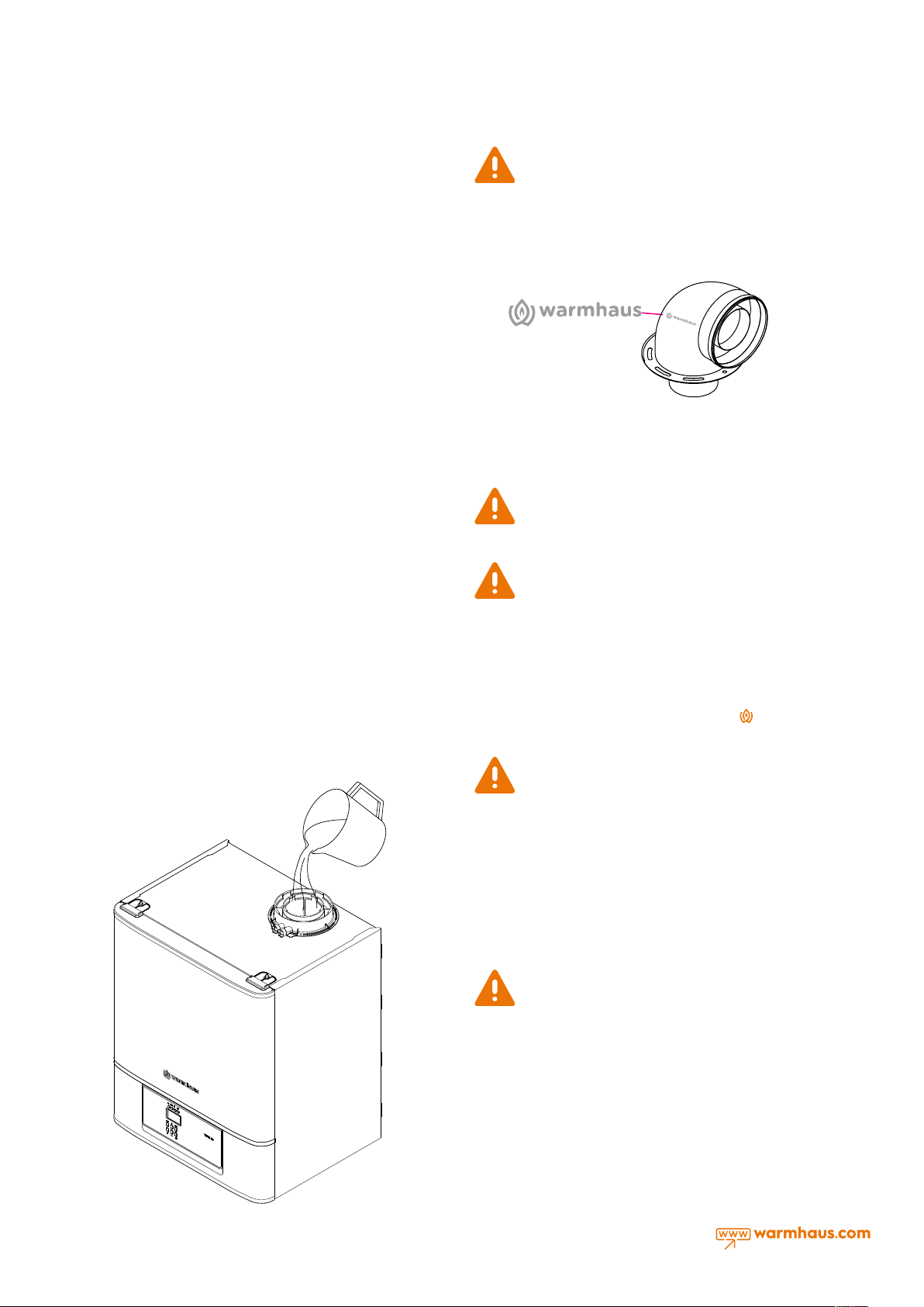
2.6. FILLING THE SIPHON FOR CONDENSATION LINE
The condensation siphon must be filled with water after completing
wall-hanging of the condensation boiler, electrical connections, heating
lines, hot domestic water connections and condensate drainage line
(Figure 10).
Condensation line outlet connection must be sealed.
However, against the risk of waste gas leak in the first
chimney-mounting of siphon in the boiler. Thus, the water in the siphon
will prevent the leakage of waste gas.
The tilt of the condensation water hose and line must always be
downward.
Figure 2.11 There is a Warmhaus log in the chimney elbow.
operation, pout about 1 litre of water into the chimney before
2.7. CONNECTION OF WASTE GAS CHIMNEY PIPE
SET AND ACCESSORIES
Chimney accessory of hermetic boilers sets to be used in
the waste gas installation should be original Warmhaus
sizes and restrictions given in the mounting instructions.
Authorized Service and therefore cannot be guaranteed!
The boiler should only be mounted with plastic material and the
original Warmhaus air intake and waste degazing device.
Plastic ducts cannot be installed outdoors, at intervals over 40 cm,
without proper protection against UV and weather conditions. Each
pipe is identified by a promoting and distinctive
the notes.
chimney sets and they should be used taking into account
If different waste gas pipes and/or accessories are used
other than original Warmhaus waste gas chimney pipes
and accessories, the boiler will not be started by the
Warmhaus sign in
12
Figure 2.10 Filling the condensation flusher
If more than one Viwa 90-150 boilers are connected in
parallel to the same hydraulic installation and operated as
cascade, it is necessary to use the product code for each
boiler is: Ø100 / 100 Waste Gas Chimney Block with 153.11.660.600040
product code or (Ø100-Ø100) Chimney Block products with
153.11.660.600068 product code must be used for each boiler. In the
same installation, the blocks should not be used together and the
same block product should be used for each boiler.
If the Viwa 90, Viwa 115, Viwa 125 and Viwa 150 boilers are used as
cascade systems and our blocking products are not used in each
boiler, boilers will not be started by our authorized service!
IMPORTANT
The following must be checked during staring the boiler:
- Make sure that there is no liquid or combustible materials
near the boiler.
- Ensure that the electrical connections are made correctly
and that the ground wire is connected to a good grounding system.
- Open the gas valve and check the durability of connections including
the burner, burner exchangers and heat exchangers.
- Ensure that the boiler is adjusted for operating for the supplied gas
type.
- Check that the chimney pipe in outlet of combustion products is not
blocked and is properly mounted.
- Make sure that any (safety) shut-off valve is open.
- Ensure that the system is filled with water and thoroughly ventilated.
- Check that the circulation pump is not jammed.
- Discharge the air that may be in the gas line, discharge the air in the
gas pipe by operating the pressure discharge valve at the gas pipe
inlet.
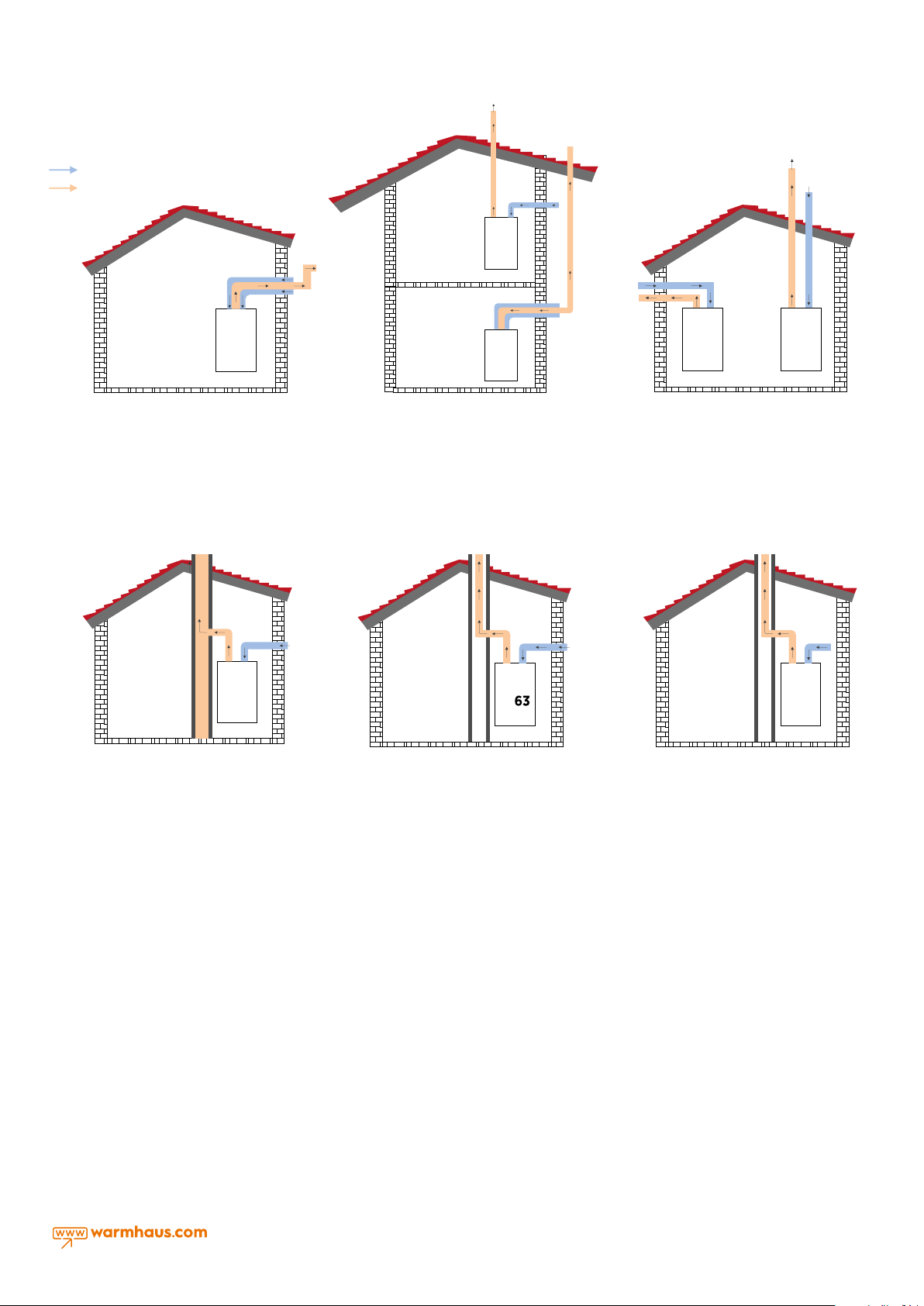
Ar
Waste Gas
C
53
13
C
Discharge with Concentric
Flue Connection
Cauton: In use of C13 type chimney, a 90°
cantilever gas directing set must be installed on
Figure 2.12 Hermetic (concentric) and
Chimney (Split-Flue type)
the cage end.
C83
Discharge to Building Chimney
with Split-Flue Connection
and Fresh Air Intake
For C8 type sealed boilers with combustion
a) overheating combustion products temp.:
b) CO2 content; 9.00% (tolerance +0.5%/-0.5%)
c) Chimney characteristics to which the boiler
can be connected depend on Figure 2.15.
d) Condensation water isn’t allowed to flow
Figure 2.15 Hermetic vertical Split-Flue
connection.
chamber;
<105 °C
into device.
C
53
Exhaust Gas Discharge and
Fresh Air Intake with Concentric
Flue Sets and Split Flue Sets
Cauton: Terminals should not be mounted against
building walls for supply of combustion air of C5
type sealed boilers with combustion chambers and
discharge of combustion products.
Figure 2.13 Hermetic concentric and vertical
Split-Flue connection.
C
Exhaust Gas Discharge from Building
Chimney with Split-Flue Kits and
Fresh Air Intake From The Outside
For C6 type sealed boilers with combustion chamber
a) for chimney, overheating combustion products temp.: <105 °C
content in nominal operating conditions; 9.00% (tolerance
b) CO
2
+ 0.5% / -0.5%)
c) dierence of the maximum permissible draught and the
maximum permissible pressure between combustion air inlet and
chimney gas outlet (including wind pressures): 120 Pa.
d) characteristics and applications of the duct system to which the
boiler can be connected;
1) Condensation water isn’t allowed to flow into device.
2) maximum permissible temperature of the combustion air; 40°C
3) maximum permissible recirculation rate in wind conditions is 10%.
Caution: Terminals should not be mounted against building walls for
supply of combustion air and discharge of combustion products.
Figure 2.16 Connection of hermetic split-flue
and building chimney
C33C33
Exhaust Gas Discharge Fresh Air
Intake with Split Flue Sets
Cauton: In case of using C33 type Split-Flue Set (for
horizontal and vertical types), the distance
between the exhaust gas outlet and the clean air
intake should be minimum 50cm, maximum 100cm.
Figure 2.14 Vertical Type Hermetic
Use with Split-Flue Set
B
23
Exhaust Gas Discharge from Building
Chimney with Split-Flue Sets and
Fresh Air Intake From The Inside
Figure 2.17 Chimney use with split-flue
set
2.7.1. Environmental Distances of Chimney Outlet Connections
See Figure 16 for positioning the outlet pipe of chimney set. The
chimney must be mounted in accordance with national and local
regulations.
Any part of the outlet pipe should not be blocked and should not
interfere with other connections. If the outlet pipe is passing 1000 mm
near a plastic or painted conduit or 500 mm near the painted eaves, an
aluminium guard of at least 1000 mm in length should be placed under
the conduit or eaves. The outlet pipe should be at least 2 m above the
surface that people can reach. In some weather conditions, the outlet
pipe may emit water vapor; so it should not be mounted in places
where this vapor may cause irritation.
It should be ensured that combustion products (waste gas) do not
enter the roof ventilation openings. The boiler chimney system can be
installed inside the room without the need to intervene on the outside
wall. To do this, especially in thick walls, a bed must be used in the wall
for lining the inner surface of the duct, through which the outlet pipe
passes through the wall.
13

Figure 2.18 Ø 80/125 mm Concentric Chimney Set
1. 90° elbow
2. Sealing gasket
3. Sealing gasket
4. Centring wire
5. Exterior chimney pipe
6. Inner wall blind flange
7. Outer wall blind flange
8. Interior chimney pipe
9. 60 Sealing gasket
10. Protection cage
11. Flange gasket
12. Flange connecting screws
13. Control measurement stopper
14. Fresh air control cover
• Concentric extension pipes and plug-in type
seal for elbows. To connect the possible
extension connections of the waste gas
chimneys to other elements of chimneys:
connect the male (straight) side of concentric
pipe or concentric elbow to the female
side (sealed side) of the previous part, in this
case make sure you have fitted the required
washer, so the connection will be tight and
integrity of parts of the set will be ensured.
Please note that in the case where
shortening of the discharge chimney
and/or extension is required, the
inner chimney must always be 5 mm ahead of
the outer pipe.
For safety reasons, the absorption/
discharge chimney of the boiler
should not be blocked, even if for
short-time or temporarily.
During installation of the horizontal
pipes, the pipe tilt must be kept
upwardly a minimum of 3%, dowelled
in every 3m and a retaining clamp must be
used.
Figure 2.20 Combi concentric chimney wall outlet for hermetic use.Figure 2.19 Installation of chimney set parts
All horizontally fitted ducts (air/flue)
should be fitted at a slight 2° or 3°
upwards incline to allow
condensate water drain to the boiler.
• The parts of standard horizontal flue
kit are available in "Concentric (Optional)
Chimney Accessories (Ø100/150 mm) for
VIWA 90, 115, 125 and 150".
The horizontal flue connections should
be assembled as to have an upwards
inclination of 2° or 3° as to allow the return
of condensate to the device.
o
3
Figure 2.21 Condensed boiler chimney tilt
Ø100/150 mm
a + b + c + d < 19 m = (Viwa 90)
19 m = (Viwa 115)
18 m = (Viwa 125)
10 m = (Viwa 150)
d
b
a
Figure 2.22 II. Two 90° cantilever sample chimney ins-
tallation
c
a- Horizontal Chimney Set Elbow (90°)
b-Chimney Extension Pipe
c- Additional 90 ° Elbow
d-Horizontal Chimney Set Pipe
The total length of the
concentric chimney set must
not exceed 10m horizontally
with a single elbow. In additions, this
total length is reduced by 1 m for each
90° elbow use and 0.5m for each 45°
elbow use. Up to 3 90° elbow can be
used.
14
Ø100/150 mm
Lmax= 18 m (Viwa 90)
Lmax= 17 m (Viwa 115)
Lmax= 17 m (Viwa 125)
a d
Lmax= 10 m (Viwa 150)
b
Ø100/150 mm
a + b + c + d + e + f < 19 m = (Viwa 90)
19 m = (Viwa 115)
18 m = (Viwa 125)
10 m = (Viwa 150)
b c
d
a
e
a- Horizontal Chimney Set Elbow (90°)
b- Chimney Extension Pipe
c- Additional 45° Elbow
d- Standard Chimney Set Pipe
e- Additional 45° Elbow
f
f- Horizontal Chimney Set Pipe
Figure 2.23 Single 90° angled sample
chimney installation
Figure 2.24 III. Single 90° and two 45° angled
sample chimney installation
Connection of (Ø100 / 150 mm) Horizontal Concentric Chimney
Set and Mounting Horizontal Concentric Chimney Set to The
Boiler
Since your boiler is hermetic model, if it is used with concentric
chimney sets, it takes the air that it uses from the outside and emits
waste gases due to combustion to the outside from the same chimney
group. The use and installation of the chimney is very important
to avoid emission of waste gases which are extremely harmful, so
cautions should be taken into account when connecting chimney.
• Select the chimney necessary for the chimney connection from the
mounted place of your boiler and outside. If the horizontal/vertical
chimney set is insufficient, select the most appropriate elements from
our list of connection accessories, taking into account the warnings
mentioned in our operating manual.
• Fix the flange under Elbow part (1) in Figure 17 on holes on the boiler
by using the Flange Seal (10) and screwing with the flange connection
screws (11).
• Two sealing gaskets (2) from the concentric chimney set are placed in
the inner pipe slots at both ends of the 90° elbow.
• To group the chimney outlet terminal, intertwine the outer wall
(EPDM) gasket with chimney terminal as seen in Figure 17. After
intertwining the chimney outlet terminal from the outer side of wall and
previouslyopened holes insert the Internal Wall Connection Gasket (7)
in chimney terminal. Insert the other end of EPDM connection gasket
you have already inserted in 90° chimney elbow, into the chimney
outlet terminal Be careful that gaskets are placed properly.
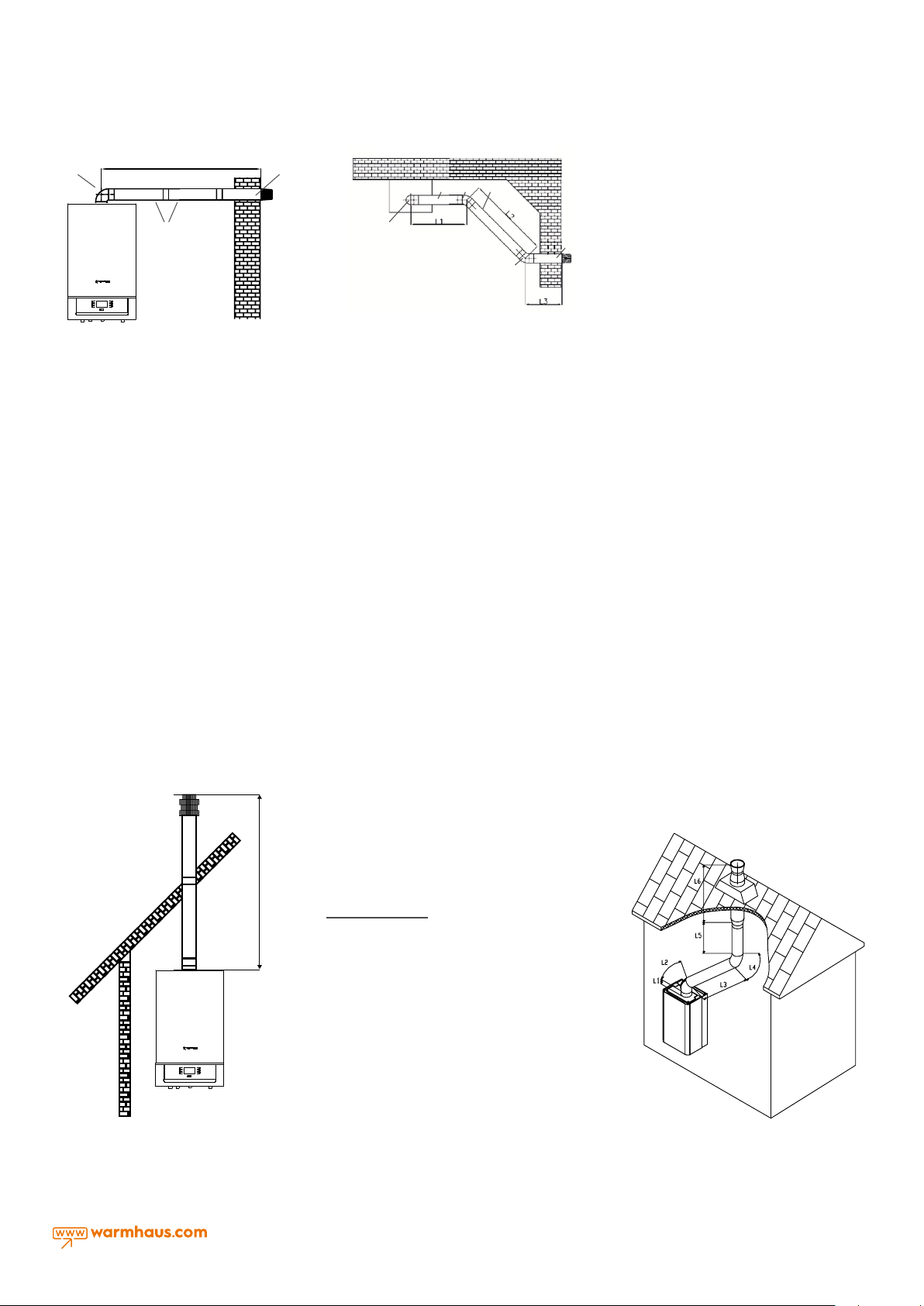
2.7.2. Mounting with Vertical Concentric Chimney Sets
The boiler also has the possibility to connect vertically to the flat
and sloped roof by means of the accessories it has according to the
situation of the environment you will mount on. In straight connections,
(Ø100 / 150 mm) vertical chimney set should not exceed 11m.
Figure 2.25 Vertical chimney set mounting
Lmax= 11 m (Viwa 150)
Lmax= 19 m (Viwa 125)
In practice
Ø100/150 mm
Lmax= 20 m (Viwa 90)
Lmax= 20 m (Viwa 115)
L1 =0.3 m.
L2 =0.5 m. (45° elbow equivalent length)
L3 =4.5 m.
L4 =0.5 m. (45° elbow equivalent length)
L5 =4.7 m.
L6 =1.0 m.
L Total =11.5 m.
Correct in practice for Viwa 90,
Viwa 115, Viwa 125 but not suitable
in practice for Viwa 150.
Figure 2.26 Vertical chimney set
mounting practice
15
 Loading...