

Warmhaus LAWA, LAWA PLUS Installation & User Manual

CONVENTIONAL COMBI BOILERS
INSTALLATION & USER MANUAL
LAWA &
LAWA PLUS
Lawa
LawaPlus
Enerwa E24
EnerwaPLUSE24

3
1. DEAR WARMHAUS
CUSTOMER
1.1. GENERAL WARNINGS
1.2. GENERAL WARRANTY CONDITIONS
1.3. GAS LEAKAGES
2. INSTALLATION PERSONNEL
SECTION
2.1. CONTENTS OF PACKING BOX
2.2. COMBI INSTALLATION RULES
2.2.1. General Rules for Installation
Places of Combi Boilers
2.2.2. Places Not Suitable for Installing
Hermetical Combi Boilers
2.2.3. Wall Installation of Combi and
Selecting the Installation Place
2.2.4. Dimensions and Connections
2.2.5. Natural Gas and LPG Connection
(Device Category I2H, II2H3P)
2.2.6. Flammable gas quality
2.2.7. In case of using LPG Tank
2.2.8. In case of using Bottled Gas
2.2.9. Radiator and DHW Use Installations
2.2.10. Exhaust Gas Flue Pipe Set and
Accessories Connection
2.2.11. Peripheral Distances of Flue Output
Connections
2.2.12. Installation with Horizontal Flue Sets
2.2.13. Installation with Vertical Flue Sets
2.2.14. Hermetic Flue Type Use
2.2.15. Installation at Partially Protected
Exteriors
2.2.16. Electrical Connections
2.2.17. Optional Controls: Room Thermostat,
External Weather Temperature Sensor
and Others
2.3. HYDRAULIC INSTALLATION RULES
2.3.1. Radiator (Heating) Water Structure
2.3.2. Filling/Emptying Radiator Installation
2.3.3. Circulation Pump
2.3.4. Controls for Initial Operation of Combi
2.3.5. Boiler Components
3. USER SECTION
3.1. GENERAL WARNINGS FOR USER
3.1.1. Use of Combi
3.1.2. External Weather Temperature Sensor
Use (Optional)
3.2. ON/OFF / STANDBY AND SUMMER
/ WINTER MODES SELECTION
3.2.1. On/Off/Standby Positions
3.2.2. Operation at Winter Position
3.2.3. Operation at Summer Position
3.2.4. Resetting the Combi (Re-Starting)
3.2.5. Shutting off the Combi
3.2.6. Selection of On/Off/Standby and
Summer/Winter Modes
3.2.7. On/Off/Standby Positions
3.2.8. Operation of Winter Position
3.2.9. Operation of Summer Position
3.2.10. Shutting off the Combi
3.2.11. Use with Room Thermostat (Optional)
3.2.12. External Weather Temperature Sensor
Use (Optional)
3.2.13. Customizing Combi Features
3.3. TROUBLESHOOTING
3.3.1. Failure Codes Table
3.4. RECOMMENDATIONS FOR
ECONOMICAL USE OF COMBI
3.5. ISSUES REQUIRED TO BE TAKEN
INTO CONSIDERATION
INDEX
4
We congratulate you for preferring the Warmhaus combi to maintain
your heating and domestic hot water comfort for long years and thank
for your trust. Warmhaus combi, manufactured in accordance with
European Union standards and advanced technology, are also being
imported to many countries. You can benefit from our Authorized
Technical Service network having occupational competency certificate
for all kinds of ordinary maintenance requirements for this product
manufactured with rigorous studies. Our Authorized Services guarantee
protection of your device performance as they always provide original
spare parts service. Carefully read this guide in order to use the combi
in an economic, comfortable and efficient way and keep as a source
of application.
In order to ensure efficient use, we initially recommend you to have
the installation performed by a certified dealer experienced and
competent in installation by the local gas authority.
1.1. GENERAL WARNINGS
Guide Book is an inseparable and integral part of the product and
should be delivered to the new user when the device is transferred.
The aforementioned book should be carefully protected and used
as well as be applicable when required as it contains important
information regarding installation.
Radiator and DHW installations should be engineered and
produced by a competent and certified engineering
company in accordance with measurements defined based
on laws by considering legal regulations in force.
Installation and Maintenance operations should be performed
by the expert personnel having adequate technical
knowledge in installations sector and occupational
competency certificate in accordance with legal regulations in
force. As the result of a false installation, dangers may occur which
the manufacturer company cannot be held responsible for and may
damage people, other live beings (animals, plants) or commodities.
Natural Gas Installation Project; One of the dealers authorized
by a gas company located at your city should be preferred for
performing project and etude studies.
In order to enable use of the combi with LPG tubes or LPG
tanks, conversation of the combi should be performed by our
authorized Warmhaus service. Project design and application
for LPG use should be performed by the company supplying
the tank in accordance with local and legal rules.
1.2. GENERAL WARRANTY CONDITIONS
The Manufacturer company shall not have any
responsibilities within or out of the agreement scope due
to failures arising from failing to follow legal regulations in
force and standards and information given in this guide book (and
information and instructions provided by the manufacturer under
any circumstances) during installation, use or maintenance
operations and device warranty shall also be void.
Only the authorized Warmhaus Service is authorized to make
the electrical connection of Combi and supplying electricity
to the combi.
The maintenance and repairs as the result of failure of the product
within the warranty period due to material, production and installation
errors shall be performed as free of charge without claiming any
workmanship costs and spare part payments.
This device should only be used for its designed intended
purposes (to be used in closed-circuit heater
installation and production of open circuit domestic hot
water production). All kinds of other uses are not suitable as well as
may create a potential danger.
Manufacturer shall not be responsible for damages occurring due
to interventions, false installation and initial starting performed by
unauthorized persons and warranty scope shall be void. As the Combi
is a device having heating system, domestic hot water, natural gas/LPG
and electrical connections, do not make and have any interventions
made without the authorized service.
Device maintenance operations should be performed by the
authorized and expert technical personnel, and
It is strictly forbidden to try to detect the gas leakage with
the help of flame.
This device has been manufactured to be installed in the
country given on the technical registry label. Performing the
installation in countries other than the country written on the
table may damage individuals, animals and commodities.
Connections sealed with bolt paint must not be opened
or changed by a person who is absolutely expert and not
approved service. These seals prove that the bolts required
for perfect and safe operation have not been changed. If the seals are
damaged, the guarantee of the device will come to an end!
Combis bear CE mark in accordance with below given directives:
- Gas Directive 2009/142/EEC
- Efficiency Directive 92/42/EEC
- Electromagnetic compatibility
- Directive 2014130/EU
Please visit the below given web site of Warmhaus for acquiring more
detailed information regarding legal regulations on installation of gas
fired heating devices: www.warmhaus.com
Manufacturer: ÇELİKPAN Isıtma ve Soğutma Sistemleri Tic. A.Ş. Bursa
Organize Sanayi Bölgesi Park Cad. No:10 16140 Nilüfer-Bursa / Türkiye
WARMHAUS
Warmhaus Authorized Technical Service Centres maintain an assurance
regarding quality and professionalism on that issue. ÇELİKPAN is not
responsible for damages arising from repairs, part replacements and
maintenances performed by third persons and companies and combi
remains out of the warranty scope under such conditions.
ÇELİKPAN A.Ş. reserves the right to make all kinds of technical and
commercial amendments without giving information and rejects all
responsibilities depending on misspelling.
1. DEAR WARMHAUS CUSTOMER
1015 16
5
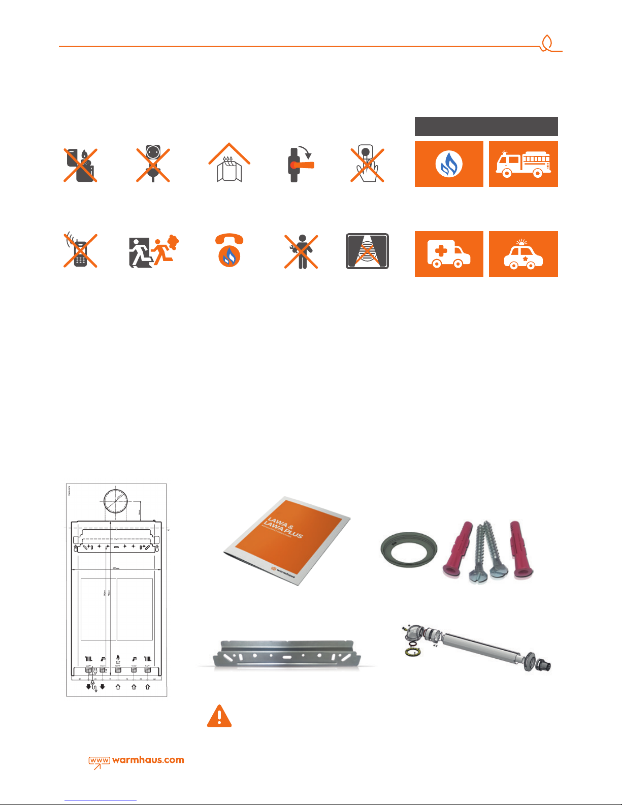
HOW TO MOVE WHEN NATURAL GAS ODOUR IS DETECTED...
1.3. GAS LEAKAGES
2. INSTALLATION PERSONNEL SECTION
2.1. CONTENTS OF PACKING BOX
Warmhaus is sold as two boxes containing combi
and flue set. Combi box contains below listed
materials and smaller box contains exhaust
gas flue pipes.
I. Installation Scheme (Figure 1)
II. User Guide (Figure 2)
III. Connection Accessories (Figure 3)
a. 1 Throttle screw (installed at flue output).
b. 2 Hanger screws
c. 2 Dowels
IV. Hanger Plate (Figure 4)
V. Exhaust Gas Flue Set (Figure 5)
Figure 1 Installation scheme
Figure 4 Hanger plate
Figure 3 Connection accessories
Do not leave packing materials (plastic,
nylon, bags, etc.)within a child’s reach
– be safe.
Figure 2 Installation Notes
Figure 5 Exhaust gas flue set
Do not use lighter
- matches.
Close valves of
devices operating
with natural gas and
your gas meter.
Immediately
evacuate the place
with gas odour.
Natural Gas
Emergency Line from
your neighbour or
another suitable place.
Do not make any
intervention on
installation.
Never close culverts
ensuring discharge
of the gas from the
environment in case of
a natural gas leakage.
Do not use the
door bell.
Do not use phones
in case of a natural
gas leakage. It may
create sparks.
Do not light on and
off lamps and other
electrical devices or pull
off the plug.
Ventilate the
environment by
opening doors and
windows.
AMBULANCE POLICE
DURING EMERGENCIES
NATURAL GAS
EMERGENCY
FIRE
DEPARTMENT
INFORMATION: You can visit web sites of
local gas authorities and NATURAL GAS
EMERGENCY sections.
Advice: Please take note local emergency
phone numbers.
6
2.2. COMBI INSTALLATION RULES
2.2.1. General Rules for Installation Places of Combi Boilers
No restriction is available for places where Hermetic (C typ) combi
is installed (devices may be installed regardless of the room volume
and ventilation type). Also, they may be installed in partially protected
areas such as balconies, terraces provided that precautions are taken to
ensure boiler is frost proof. Combi should be soundly installed against
a building wall. A flexible connection piece should be used between
the combi and gas line. Flex lengths to be used in A, B and C type
devices should not exceed dimensions allowed by local gas authorities.
Flue outputs of hermetic combis must be connected to ventilated
places with air circulation. Installation (positions of pipe output opening
based on various forms, vertical, horizontal minimum distances, cross
section areas of channels if given to channels, etc.) must be carried out
according to regulation standards, current legislation and in compliance
with local technical regulations and the required technical procedures.
2.2.2. Places Not Suitable for Installing Hermetical Combi Boilers
• Stairways of Buildings,
• Corridors available for general use, ventilation ways and shafts, lofts,
attics, emergency exit doors, cellars, hall and similar communal use
areas,
• Yards between buildings,
• Narrow cornices
• Over flue walls,
• Enclosed balconies,
• Open balconies (except being located in a cabinet approved by the
device company),
• Below protruding structure parts preventing exhaust gas output,
• Places directly subjected to wind resistance,
• It is forbidden to install Hermetic combi (C type) in openings
providing clean air to other units.
2.2.3. Wall Installation of Combi and Selecting the Installation
Place
• Wall installation for the combi boiler should be well secured.
• The hanger plate given as standard with the combi should be
installed according to the technique to a full or semi-full brick wall
according to installation scheme and with connection screws and not
to be used for other purposes.
• If different materials are used for installation, the combi shall be
rendered out of the warranty scope.
• If the wall of installation is not a brick wall, additional support will be
required..
• Combi should be installed on a wall resistant to fire.
• 1,8 - 2,2 m height is recommended for installation of the combi
hanger plate.
• For places with limited installation space, combi should be installed
at minimum of 30 cm height from ground and by leaving at
least 5 cm distance from both sides in order to allow easy access for
the service technician.
• Combi installation must not performed in environments containing
explosive, flammable substances and acid fumes.
• Installation cannot be made near or ovens, radiators or heater
devices.
• Hermetic combis can be installed in cabinets but at least 5 cm
should be left at both sides.
• If installing in a fitted kitchen at least 30 cm distance should be left
under the combi.and 5 cm each side for access.
• Do not put electronic devices, corrosive tools, components furniture
or equipment below the combi against as there may be a risk of
water leakage from the combi safety valve during installation.
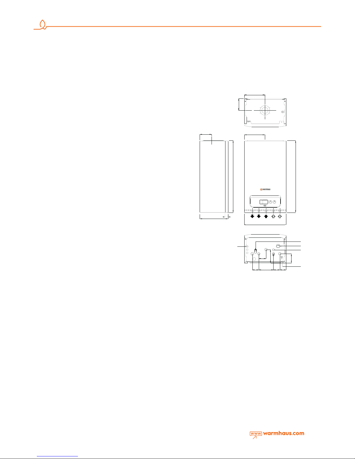
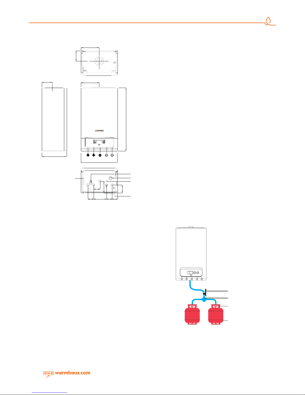
2.2.4. Dimensions and Connections
Figure 6 Lawa Combi dimensions connections
288
30
118
725
725
208
208
118
94
136
74
65 148
65
65
J
G
F
H
I
420
A B
C
D E
A CENTRAL HEATING FLOW
B DOMESTIC HOT WATER OUTLET
C GAS INLET
D DOMESTIC HOT WATER INLET
E CENTRAL HEATING RETURN
F FILLING VALVE
G MANOMETER
H PRESSURE RELIEF VALVE OUTLET
I DRAIN POINT
J 230V 50HZ AC
WARMHAUS LAWA
Warmhaus Lawa
A: Central heating flow
B: Domestic hot water outlet
C: Gas inlet
D: Domestic hot water inlet
E: Central heating return
F: Filling valve
G: Manometer
H: Pressure relief valve outlet
I: Drain point
J: 230V 50HZ AC
7
2.2.5. Natural Gas and LPG Connection
(Device Category I2H, II2H3P)
Our combi devices are manufactured to be operated with methane
gas (G20) and L.P.G. Gas supply pipes should be equal to or higher
than 3/4"G combi connections. Prior to making the gas connection, a
thorough internal cleaning should be made to all fuel supply installation
pipe furnishings as possible wastes may distort smooth operation and
reliability of the combi. Only a mains gas supply can be used with the
combi (see the label located on the combi device). In case of any
conversions to the supply, changes should only be made to the combi
by an authorised professional. Also, in case of reduced pressure, the
network dynamic pressure (methane or LPG) used for supplying the
combi should be carefully controlled and will impact the boilercombi
strength. Ensure that gas valve connection is correct. Flammable gas
supply pipe should be able to supply correct adequate gas amount to
the boiler when the combi is at full power and be projected and sized
according to force and local gas company specification and instructions
in order to guarantee the device efficiency. Connection system should
comply with gas company legal regulations.
2.2.6. Flammable Gas Quality
The combi is designed to be used with pure fuel not containing any
foreign substances; therefore, required filter systems must be available in
the gas supply line (for ensuring purification of the fuel).
2.2.7. In Case of Using LPG Tank
LPG use is recommended for heat requirements over 24 kW. New LPG
stock tanks may contain settled gas residues (nitrogen) however, that
fouls the mixture assigned to that device and may cause abnormal
operations.
- Various alloy layers may be formed during transit of LPG gas in
tanks depending on mixture compositions. That causes a change in
heating power of mixture assigned to the device and may compromise
efficiency of the device.
2.2.8. In Case of Using Bottled Gas
• 300 mmSS pressurized hood should be used for LPG.
• 500 mmSS hood should not be used.
• 370 mmSS pressurized hood should be used for Propane.
• Do not place tubes in cold places at risk of snow or.
• Do not place tubes in hot placescontaining ovens or
• Do not make connections with single tubes and use
LPG collector set for double, triple uses.
• The distance between the collector and tube should
be maximum 125 cm.
• Copper pipe installation should not used for distances
longer than 125 cm.
• Hose connection ends should be tightened with clamp
and no other tools should be used.
• Gas installation rules with use of LPG tank and industrial tubes should
comply with local standards and to be performed by expert installation
teams and certified by the company undertaking the construction. In
case of failing to fulfil these conditions, combi will not be covered
under warrantee by Warmhaus Authorized Services.
Figure 7 LawaPlus Combi dimensions and connections
LPG LPG
Ball Valve
COLLECTOR
370 mmSS
2 kg
Hood
12 kg or
24 kg
LPG TUBE
Figure 8 Combi bottled gas connection
Warmhaus LawaPlus
A: Central heating flow
B: Domestic hot water outlet
C: Gas inlet
D: Domestic hot water inlet
E: Central heating return
F: Filling valve
G: Manometer
H: Pressure relief valve outlet
I: Drain point
J: 230V 50HZ AC
420
725
MODE
RESET
+ +
208
208
118
118
288
A B
C
D E
94
136
74
65 148
65
65
G
F
H
I
A CENTRAL HEATING FLOW
B DOMESTIC HO T WATER OUTLET
C GAS IN LET
D DOMESTIC HOT WATER INLET
E C ENTRAL HEATING RETURN
F FILLING VALVE
G MANOMETER
H PRESSUR E RELIEF VALVE OUTLET
I DRAIN POINT
J 230V 50HZ AC
J
WARMHAUS LAWA PLUS
8
2.2.9. Radiator and Domestic Hot Water Installations
Radiator and ground heating installation should be constructed in
accordance with technical specifications and heat loss calculation.
Radiator type and amount and ground heating installation pipe amount
should comply with the heat loss calculation.
• Radiator installation should be designed as resisting to at least 6 bars.
• If the city grid pressure is higher than 6,5 bars, pressure reducer must
be installed.
• It is recommended to construct the radiator installation as double line
and without using bends and joints as much as possible.
• Strainer filter must be installed in radiator return and tap water (city
grid) input line.
• For example; as the radiator cycle's 8 litres expansion (24 kW) tank
can support maximum (80 ⁰C in radiator system) 140 litre and
(55. ⁰C in ground heating system) 170 litre installation water expansion,
additional expansion tank should be used for larger installation volumes.
170 litre installation water expansion, additional expansion tank should be
used for larger installation volumes.
• If the room thermostat and thermostatic radiator valve will be used
together; thermostatic valve should not be installed in radiators in the
place where room thermostat is available.
• Cross connection must be made for efficient functioning in radiators
longer than 1,5 m.
• Covers should be used for radiator and domestic hot water wall
passages and fixed with wall clamps to prevent expansions due to
heating.
• Combi can function under minimum 0,5 bar domestic hot water
pressure and that corresponds to a very low flow rate and therefore,
it shall not possible to adjust the requested domestic hot water
temperature. For this reason, domestic hot water line should be installed
at shortest distance with pipe having at least ½” internal diameter and
by using bends as low as possible. At least 1 bar pressurized grid input
water should be supplied to ensure adequate domestic hot water.
Hydrophore should be used if required.
• Prior to filling the radiator installation, it must be flushed and all wastes
must be cleaned
2.2.10. Exhaust Gas Flue Pipe Set and Accessories Connection
Flue accessory sets to be used in exhaust gas installation of Hermetic
combis should be original Warmhaus flue sets and they should be used
according to installation instructions.
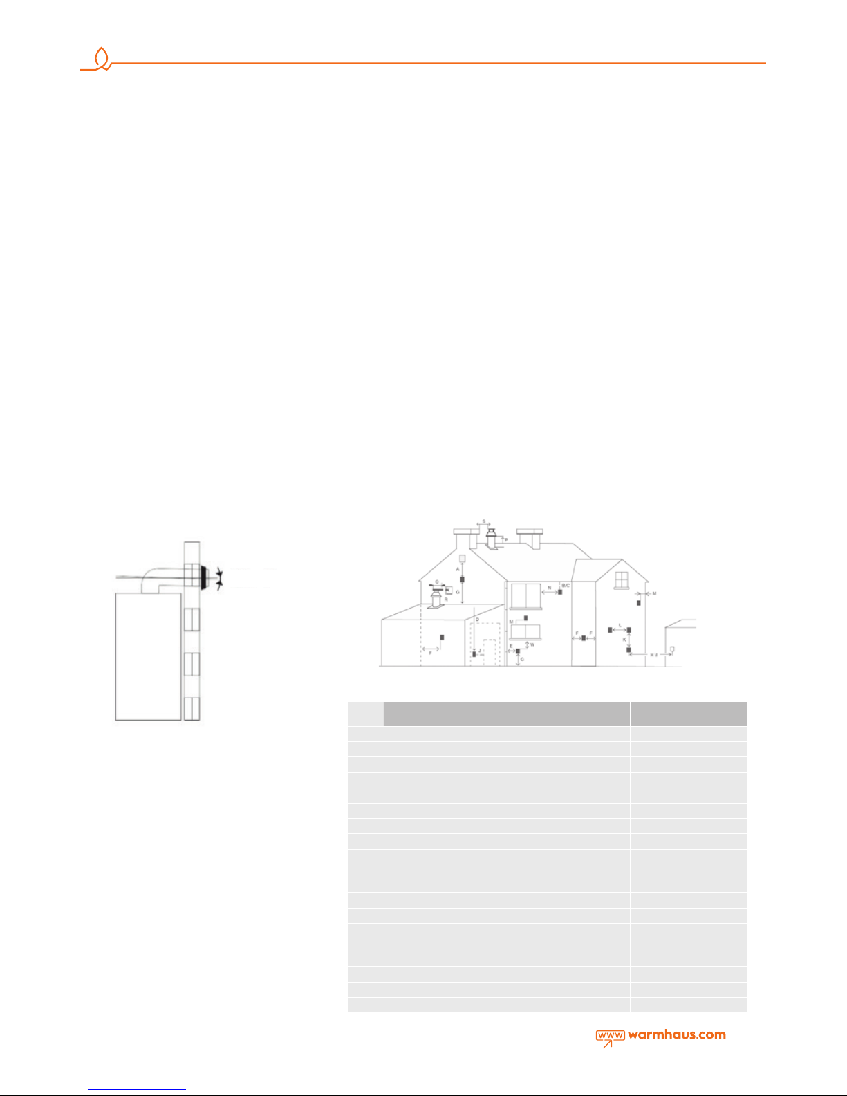
2.2.11. Peripheral Distances of Flue Output Connections
See Figure 10a for placement of flue set output pipe.
Flue should be installed in accordance with national and local directives.
No part of the output pipe or connections should be blocked. If the
output pipe passes 1000 mm nearby of a plastic or painted groove
or 500 mm of painted fringes, an aluminium shield with at least 1000
mm length should be placed below the groove or fringe. Output pipe
should be at least 2 m over surfaces within reach by individuals.
Under certain weather conditions, output pipe may emit water vapour;
installation should not be performed at places where this vapour may
cause discomfort.
Exhaust gases should be prevented from entering flue ventilation
spaces. Flue system of combi may be installed from inside the room
without requiring intervention from the external wall. For that reason, a
housing should be installed in the wall for lining the internal surface of
channel wherein the output pipe passes through the wall, particularly
for thick walls.
Figure 9 Condensing combi flue slope
Figure 10 Flue peripheral positions
Flue Position Minimum Distance
A
30 mm under a window
B
Under water groove 75 mm.
C
Under fringes 20 mm.
W
Under balconies 200 mm.
E
To vertical water discharge pipes 150 mm.
F
interior or exterior corners 300 mm.
G
At ground, roof or balcony level 300 mm.
H
On another wall corresponding to the flue 600 mm.
S
To another flue
To another wall than the garage wall
1200 mm.
J
To another wall than the garage wall 1200 mm.
R
To another flue than the same wall (vertical) 1500 mm.
Q
To another flue than the same wall (vertical) 300 mm.
M
On another window/culvert
On another window /culvert vertically
300 mm.
P
On the roof level 300 mm.
F
To an adjacent wall 300 mm.
I
To the window on adjacent wall 300 mm.
L
To another flue 1000 mm.
The air flue terminal
should be fitted at %3
downwards incline to
prevent any water drop
or condensation water
from entering the boiler
Bevel 3⁰
9
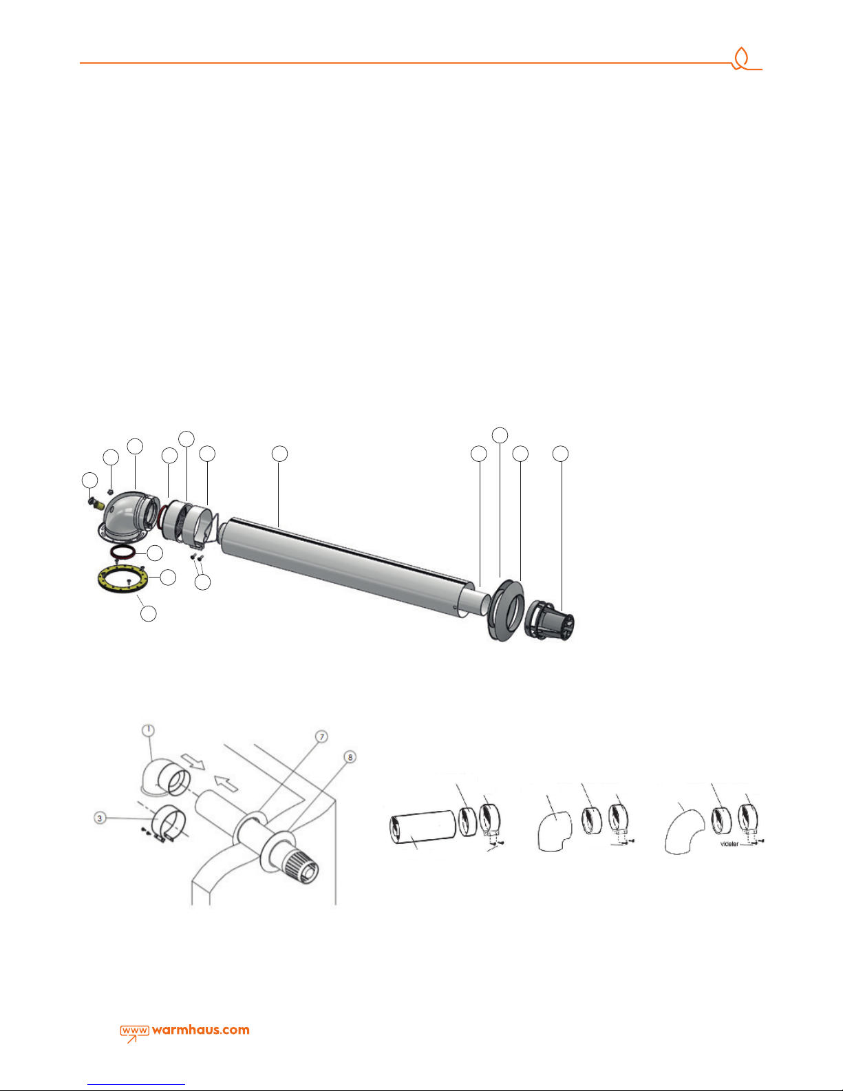
2.2.12. Installation with Horizontal Flue Sets
Connecting Horizontal Hermetic Flue Set to the Combi
Since your combi is a hermetic model, it takes the used air from
outsideand discharges exhaust gases created as the result of burning
through the same flue group. In order to prevent emission
of excessively harmful exhaust gases, flue usage and installation is very
important, therefore warnings should be taken into consideration when
flue connections are being performed.
• Make required flue selection for the external flue connectionIf the
standard flue set is not adequate, please select most suitable elements
from our list of connection accessories considering warnings given in
our user guide.
• Fix the flange under the Bend piece (1) by using the Flange Bolt (10)
via Flange Connection Screws (11) to holes on the combi.
• 2 impermeability bolts within the hermetic flue set (2) are placed into
internal pipe slots at both ends of the 90° Bend.
• Place the EPDM Connection Bolt (8) on the 90° bend contacting with
the restrictive set within the bolt.
• Place the exterior wall (EPDM) bolt into the flue terminal as seen in
Figure 11a for grouping the flue output terminal. After placing the flue
output terminal through exterior of wall and the previously made hole,
fix the Interior Wall Connection Bolt (7) into the flue terminal. Place
other end of EPDM connection bolt installed on 90° flue bend of your
combi to the flue output terminal and the clamp (3) should be insatlled
on the EPDM connection bolt and slightly tighten with screw (Figure 12).
Then fit the 90° bend on flue connection flange and fix with tightening
screws. Finally, after tightening screws placed on EPDM bolt and left
loose, push the interior wall connection bolt on the wall surface and
ensure flue and wall impermeability.
In case the hermetic flue set available in the product package does
not have adequate length, hermetic flue accessories should be ordered
from an authorized Warmhaus dealer according to requirements, nonoriginal hermetic flue accessories should never be used.
- Hermetic flue set accessories for horizontal connection;
a) Extension pipe (1000 mm), EPDM bolt, clamp and clamp screws.
b) 90° bend, EPDM bolt, clamp and clamp screws.
c) 45° bend, EPDM bolt, clamp and clamp screws.
1. 90° bend
2. Sealing gasket
3. EPDM connection bolt
4. Clamp
5. Exterior flue pipe
6. Interior flue pipe
7. Interior wall closing flange
8. Exterior wall closing flange.
9. Protection cage
10. Flange gasket
11. Flange connection screws
12. Clamp screws
13. Fresh air control cap
14. Control measurement cork
Figure 12 Hermetic combi homocentric flue wall output
Figure 13 Installation of flue set pieces
11
10
14
13
1
2
3
4 5 6 8 9
7
2
12
Figure 11 Hermetic combi homocentric flue set.
EPDM Sealing Ring
Metal collar Metal collar
Metal collar
Screw
Screw
90° Elbow
45° Elbow
EPDM Sealing Ring for 90° Elbow EPDM Sealing Ring for 45° Elbow
Concantric Extension
 Loading...