

Page 1
Page 2

Page 3

Page 1
Contents Page
User Instructions .....................................................................................................................................................................
2
Combi Boiler Pre-Installation Requirements ........................................................................................................................
4
1.0 General Information
1.1 Introduction .....................................................................................................................................................
5
1.2 General Requirements .....................................................................................................................................
5
1.3 Combi General Requirements ..........................................................................................................................
6
1.4 Baffle Positioning .............................................................................................................................................
6
1.5 Components ...................................................................................................................................................
7
2.0 Technical Details
2.1 Combi Sequence of Operation Flow Chart ....................................................................................................17
2.2 Dimensions ...................................................................................................................................................18
2.3 Flue Options & Dimensions ............................................................................................................................
23
2.4 Technical Data ...............................................................................................................................................
24
3.0 Electricity Supply & Wiring Details
3.1 Dual-Safe Thermostat (Non-Combi Models) ..................................................................................................
33
3.2 RDB Burner Control Box ...............................................................................................................................
33
3.3 Combi Wiring Details .....................................................................................................................................
34
3.4 Installation of a Warmflow Combi Optional Programmer (PC1) .......................................................................
37
3.5 Remote Timers for Combis ............................................................................................................................
38
3.6 Optional Programmer (PU1) for Non-Combi Models ......................................................................................
39
4.0 Oil Supply
4.1 One Pipe Gravity System ...............................................................................................................................
43
4.2 Two Pipe System ...........................................................................................................................................
44
4.3 De-aerator System ........................................................................................................................................
44
4.4 One Pipe Lift System .....................................................................................................................................
45
5.0 Flues
5.1 Installation of Balanced Flues
.........................................................................................................................46
5.2 Conventional Flues ........................................................................................................................................
48
5.3 Low Level Balanced Flue Terminal Positions ..................................................................................................
48
6.0 Air Supply for Combustion & Ventilation
6.1 Open Flue Boilers ..........................................................................................................................................
50
6.2 Balanced Flue Boilers – Boilers in a Compartment .........................................................................................
50
7.0 Installation Requirements
7.1 General Requirements ...................................................................................................................................51
7.2 Sealed Systems ............................................................................................................................................
52
7.3 Combi Domestic Hot Water ...........................................................................................................................
53
8.0 Burners
8.1 RDB Burner ...................................................................................................................................................
54
8.2 Oil Pump .......................................................................................................................................................
54
8.3 Electrode Setting ...........................................................................................................................................
55
8.4 Burner Start-Up Cycle ...................................................................................................................................
55
8.5 Air Damper Adjustment .................................................................................................................................
55
9.0 Commissioning & Servicing
9.1 Commissioning
..............................................................................................................................................56
9.2 Servicing .......................................................................................................................................................
56
10.0 Burner Fault Finding
10.1 Riello RDB .....................................................................................................................................................
57
11.0 Combi Fault Finding
11.1 Central Heating .............................................................................................................................................
58
11.2 Domestic Hot Water ......................................................................................................................................
59
12.0 Optional Boiler Mounted Digital Timer
12.1 Operating Instructions ...................................................................................................................................
60
13.0 Spares
13.1 RDB 2.2 Spares ............................................................................................................................................
64
13.2 Pipe Spares ...................................................................................................................................................
65
13.3 Short Parts List – Boiler .................................................................................................................................
67
14.0 Your Guarantee, Terms & Conditions .....................................................................................................................
68
Commissioning/Service Record .............................................................................................................................69
Page 4
Page 2
USER INSTRUCTIONS
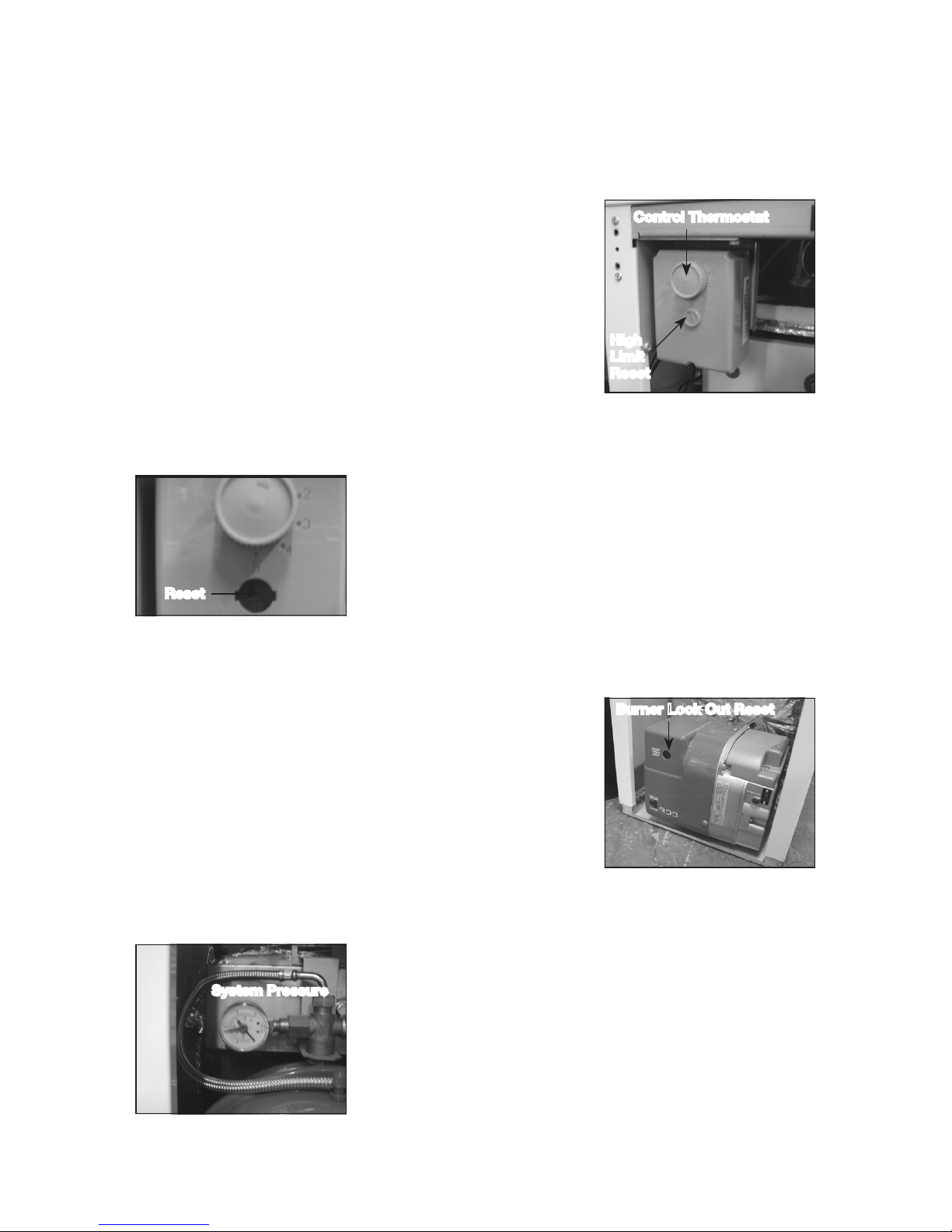
Dual Thermostat
The radiator temperature is regulated via the
boiler control thermostat. The thermostat is user
adjustable from 55°C at its minimum setting (dial
‘0’) to 85°C at its maximum setting (dial ‘5’). In
order to provide an additional level of safety there
is a high limit thermostat which has a cut off point
of 110°C; this is factory set and is not adjustable.
If thermostat trips it needs to be reset manually.
High Limit Thermostat Reset
If the high level thermostat trip has operated,
remove the reset cover by using a coin or
screwdriver (turning anti clockwise) and press the
small red button now exposed. Do not press the
reset button while the boiler is still hot as this will
cause damage to the thermostat.
Burner Lockout
When the pressure jet oil fired burner stops after
failing to fire the red reset button will be illuminated.
This indicates that there is a fault or there is no
fuel getting to the burner. The house holder should
only reset the burner twice in succession. If the
burner continues to lockout contact Warmflow or
your service engineer.
System Pressure – System & Combi Boilers
When the boiler is connected to a sealed system
the system pressure should be periodically
checked. The minimum pressure, as indicated by
the black needle, is 0.5 bar when the boiler is cold
and 2.5 bar when the boiler is at normal operating
temperature. If the pressure is outside this range
contact Warmflow or your installer.
Control Thermostat
High
Limit
Reset
Notes
USER INSTRUCTIONS
Dual Thermostat
The radiator temperature is regulated via the
boiler control thermostat. The thermostat is user
adjustable from 55°C at its minimum setting (dial
‘0’) to 85°C at its maximum setting (dial ‘5’). In
order to provide an additional level of safety there
is a high limit thermostat which has a cut off point
of 110°C; this is factory set and is not adjustable.
If thermostat trips it needs to be reset manually.
High Limit Thermostat Reset
If the high level thermostat trip has operated,
remove the reset cover by using a coin or
screwdriver (turning anti clockwise) and press the
small red button now exposed. Do not press the
reset button while the boiler is still hot as this will
cause damage to the thermostat.
Control Thermostat
High
Limit
Reset
Reset
Notes
Burner Lock Out Reset
System Pressure
Page 5
Page 3
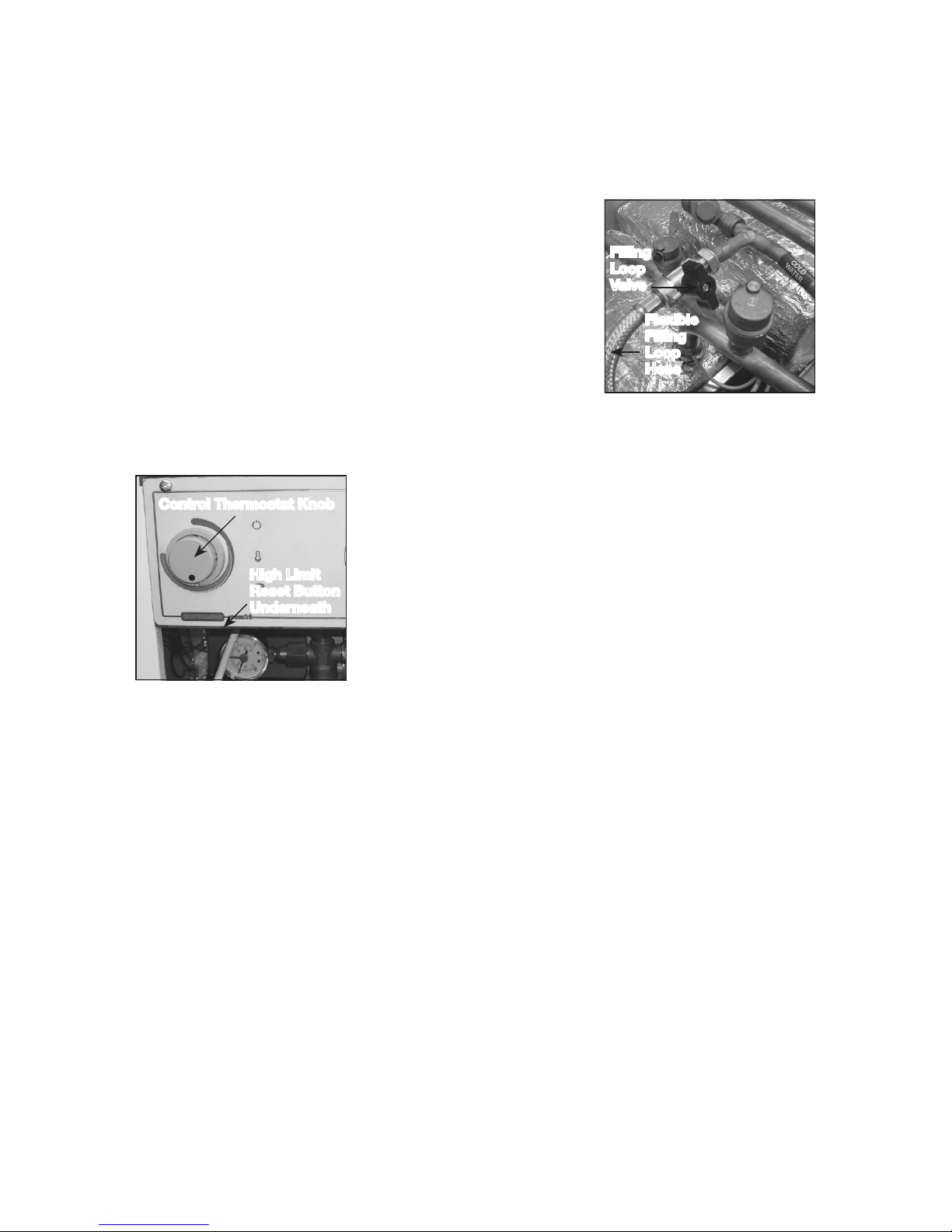
Filling Loop
If the system pressure falls below the minimum
(eg, removal of radiator for decorating purposes)
then the system should be topped up using the
filling loop valve. After the system has been topped
up the pressure gauge should read 1 bar when
the system is cold. The valve must be fully closed
and the filling loop flexible removed from the valve,
expect a small water loss from the pipe.
Combi Control Panel
The heating control thermostat is user adjustable
from 55°C to 85°C. In order to provide an
additional level of safety there is a high limit
thermostat which has a cut off point of 110°C;
this is factory set and is not adjustable. The high
limit thermostat is located under the control
panel to the left hand side, press button to reset.
As standard the panel is fitted with two on/off
selector switches to control hot water and central
heating. These switches can be replaced by the optional two channel digital
programmer, instructions for use are provided in the main boiler handbook.
This boiler must be serviced annually. Contact Warmflow for further
details.
In the event of a breakdown please contact your commissioning engineer
who should then contact our service department whilst at your home, to
report the fault.
High Limit
Reset Button
Underneath
Filling
Loop
Valve
Flexible
Filling
Loop
Hose
Control Thermostat Knob
Page 6

Page 4
BEFORE FITTING A COMBI BOILER
THE INSTALLER MUST CHECK:
1. What the maximum hot water demand placed on the boiler is likely
to be. Not every installation is suitable for a Combi boiler. Systems
requiring very high hot water flow rates may be better suited with an
unvented cylinder.
2. That the mains are capable of supplying up to 24 litre/min with a
minimum dynamic pressure of 1.8 bar at the boiler. This is to ensure that
the boiler can achieve its maximum output. To protect the appliance
and to prevent excessive flow rates, a pressure reducing valve must be
fitted to limit the maximum supply pressure to 3 bar.
3. Where the mains water pressure is supplied via a borehole pump and
accumulator the pressure variation must not affect the thermostatic
mixer valve. Contact Warmflow for further details.
4. The hardness of the mains water supply. Systems with hard water must
be fitted with a suitable chemical scale preventer (eg Fernox Quantomat
or Combimate).
5. That the flow from any one hot water outlet does not exceed the
maximum recommended. This applies particularly to baths which are
usually fitted with larger taps and larger bore supply pipes. It may be
necessary to restrict the flow to these taps by reducing the bore of the
supply pipework (eg 15mm) or by fitting a restrictor into the pipework.
6. That any outlet when opened does not starve all the other outlets of hot
water. If more than one outlet is open at the same time then the total
flow from all the outlets should not exceed the maximum flow rate of
the boiler.
7. That any showers being supplied with hot water by the boiler are
compatible with this type of appliance.
It should be noted that the boiler has been factory fitted with an
18 litre/min flow restrictor.
The manufacturer’s guarantees are void if the appliance is not installed
and commissioned in accordance with the recommendations made
herein.
Page 7

Page 5
1.0 General Information
1.1 Introduction
Note: All our domestic appliances have been independently tested and
accredited as exceeding the minimum SEDBUK efficiency levels required for
their type, in compliance with the Building Regulations Approved Document
L1A, L1B for England and Wales, the Building Standards (Scotland)
Regulations Section 6, Part F Northern Ireland and Part L Republic of
Ireland.
Warmflow standard efficiency boilers are designed for use only on fully pumped
(sealed or open-vented) heating systems and to burn Class C2 kerosene and
Class D gas oil. Note that with class D gas oil the flue MUST exhaust at more than
2m above the surrounding ground level. The low-level flue supplied as standard with
all Kabin Pak models is NOT suitable for Class D gas oil. Alternative options are
available – please contact Warmflow.
As standard the Combi and System boilers are fitted with a system expansion
vessel, circulating pumps, filling loop, pressure gauge and safety valve. An optional
7-day electronic programmer kit is also available for all Utility boiler models.
The Combi can provide at mains pressure domestic hot water without the need for
a storage cylinder.
The manufacturer’s guarantees are void if the appliance is not installed and
commissioned in accordance with the recommendations made herein.
1.2 General Requirements
The installation of the boiler must be in accordance with the following regulations.
BS5410 : PART 1 Code of practice for oil firing.
BS5449 : PART 1 Forced circulation hot water systems.
BS7593 : Treatment of water in domestic hot water central heating systems.
Current Building Regulations Part J England and Wales
Section 3 Scotland
Part L Northern Ireland
Part J Republic of Ireland
Current IEE Regulations
BS7074 : PART 1 Application Selection & Installation of Expansion Vessels
The heating system should be installed by a competent installer in accordance with
the recommendations laid down by HVCA, OFTEC and sound engineering practice.
In order to comply with the building regulations OFTEC forms CD10 for
installations and CD11 for commissioning should be left with the customer.
Alternatively the installation can be inspected and approved by a building
control officer. CD10 and CD11 forms are available from OFTEC on
Tel: 0845 658 5080, Fax: 0845 658 5181.
Page 8
Page 6
1.3 Combi General Requirements
The boiler will have a DHW priority when both domestic hot water (DHW) and central
heating (CH) are selected. So if the flow switch is closed or the heat store has not
been satisfied the entire output of the boiler is directed to DHW before the boiler will
switch over to CH. When fully cold it can take up to 20 minutes for the heat store of
a 90,000 Btu/h Combi to be satisfied, and slightly longer for a 70,000 Btu/h Combi.
After a draw-off of 120L at 24L/min, with an average temperature rise of 32°C, the
thermal store of a 90,000 Btu/h Combi has a recovery time of approximately 7 mins.
A 70,000 Btu/h Combi will take slightly longer to recover.
Note: If HW has not been selected no hot water can be produced even if the heat
store is up to temperature.
1.3.1 Pump Overrun
Where there is a build up of excess heat in the boiler heat exchanger and the central
heating has not been selected then the pump overrun thermostat will operate. The
excess heat will then be pumped into the heat store. Once the temperature has
fallen in the boiler and the pump overrun stat is satisfied or the central heating pump
starts to operate, then the hot water pump will stop.
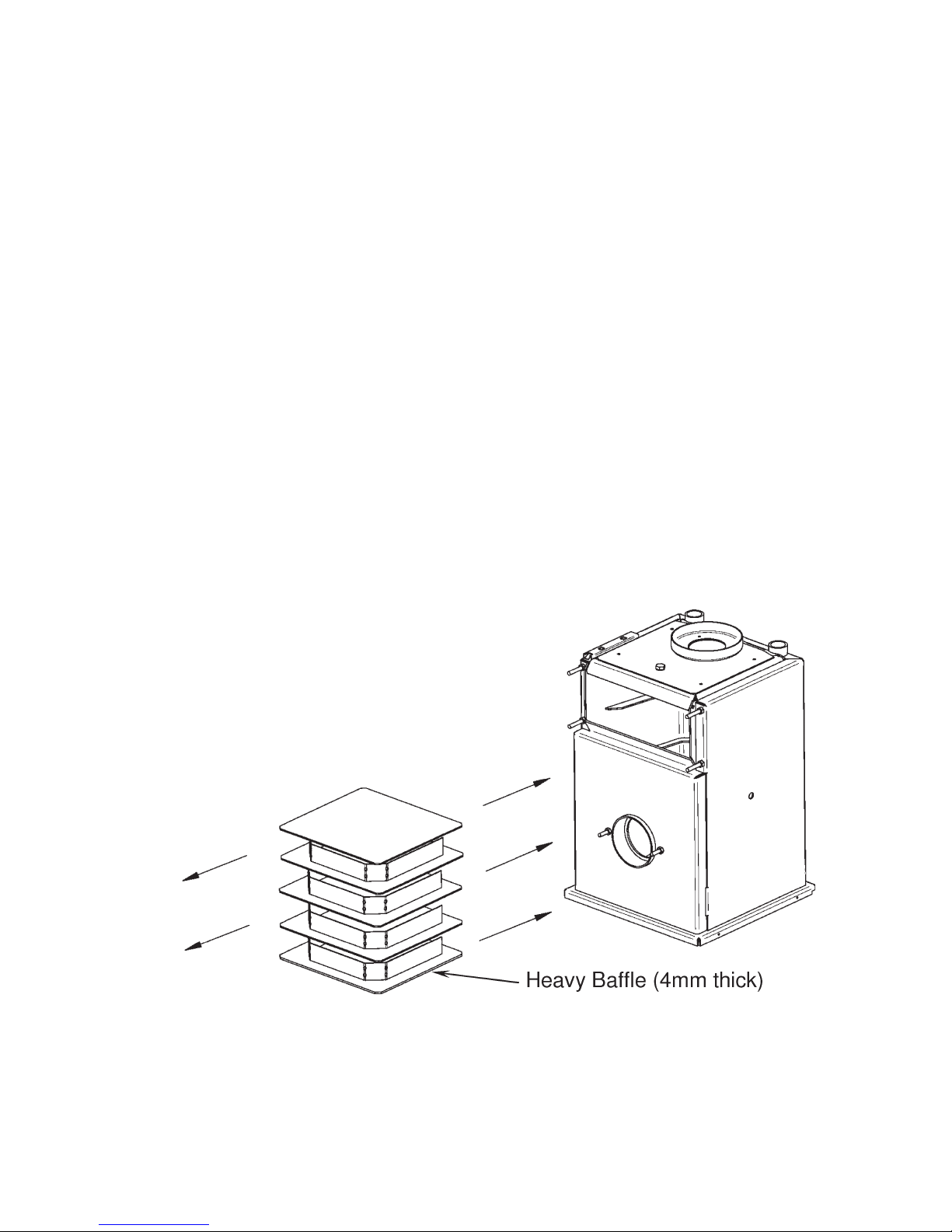
1.4 Baffle Positioning
The heat exchanger baffles consist of one heavy baffle stack (4mm thick) at the
bottom, 3 lighter baffle stacks (3mm thick) in the middle and 1 baffle plate (3mm
thick) at the top. Upon installation or after servicing, ensure the baffles are in the
correct order and correctly stacked.
Page 9
Page 7
1.5 Components
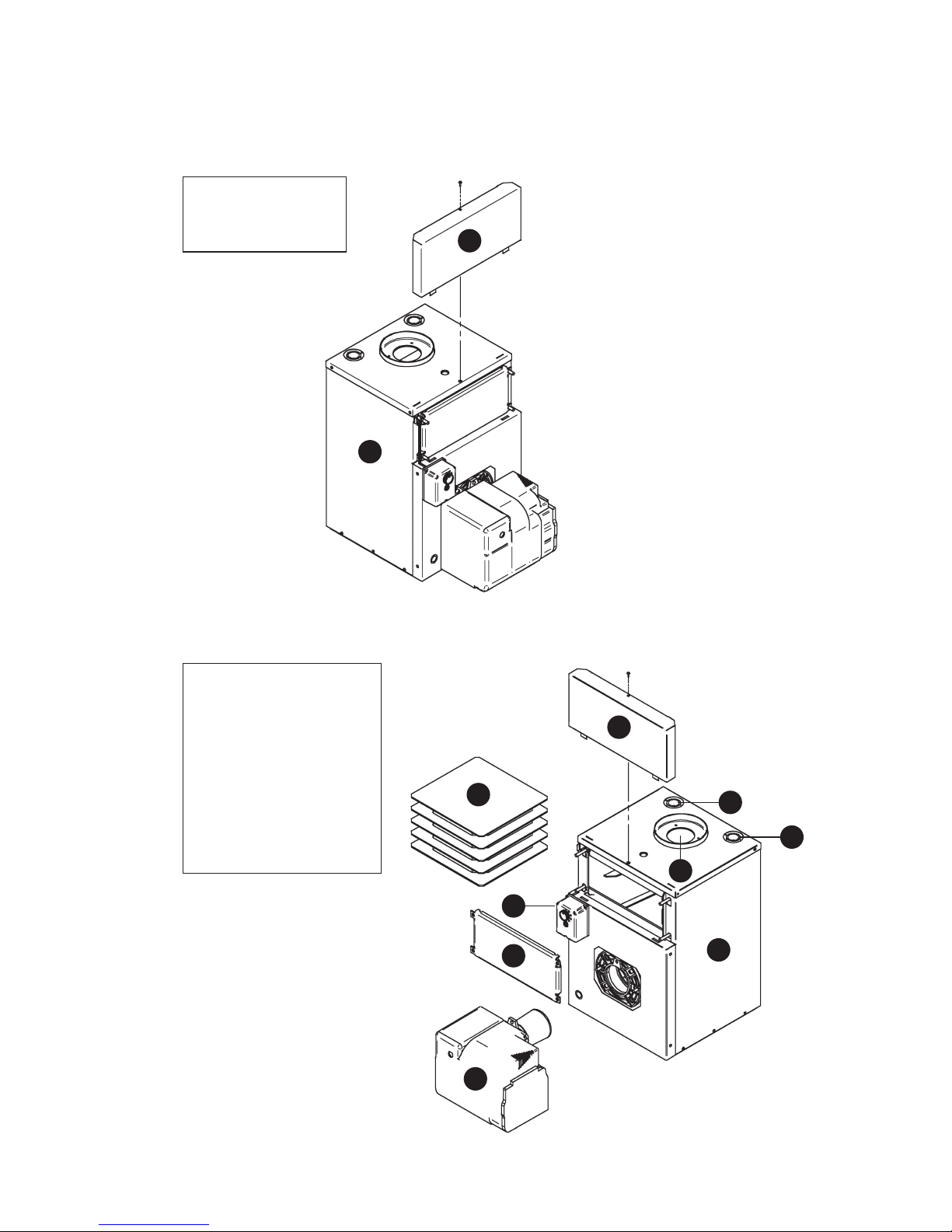
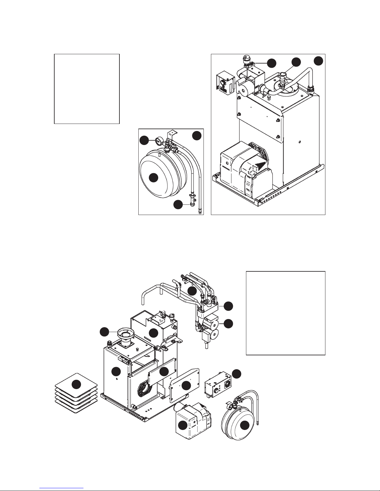
1.5.1 B-Series Boilerhouse – Casing Components
1. Boiler Assembly
with Casing
2. Service Door
Cover (removable)
1.5.2 B-Series Boilerhouse (B70, B90 & B1) – Key Components
1. Heat Exchanger
with Casing
2. Service Door Cover
3. Heat Exchanger Baffles
4. ‘Dual-Safe’ Thermostat
5. Service Door
6. Riello RDB 2.2 Burner
7. Flue Ring
8. Heating Flow
Connection
9. Heating Return
Connection
1
2
1
2
3
4
5
6
7
9
8
Page 10
Page 8
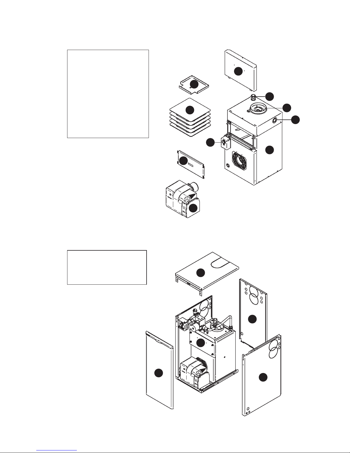
1.5.3 B-Series Boilerhouse (B120) – Key Components
8
1. Heat Exchanger
Assembly with Casing
2. Service Door Cover
3. Secondary Exchanger
Inspection Lid
4. Primary Exchanger Baffles
5. ‘Dual-Safe’ Thermostat
6. Service Door
7. Riello RDB 2.2 Burner
8. Flue Opening
9. Heating Flow
Connection x 2
10. Heating Return
Connection
1.5.4 U-Series Utility – Casing Components
1. Boiler Assembly
2. Top Casing (removable)
3. Rear Casing
4. Side Casing
5. Front Casing (removable)
1
2
3
4
5
6
7
9
10
1
2
3
4
5
Page 11
Page 9
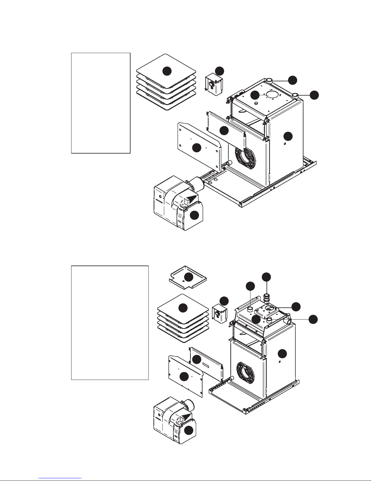
1.5.5 U-Series Utility – Pre-Wired (U70 & U90) – Key Components
1. Heat Exchanger
2. ‘Dual-Safe’
Thermostat
3. Heat Exchanger
Baffles
4. Service Door
5. Service Door
Cover
6. Riello RDB
2.2 Burner
7. Flue Opening
8. Heating Flow
Connection
9. Heating Return
Connection
1
4
6
7
3 2
9
5
1.5.6 U-Series Utility – Pre-Wired (U120) – Key Components
1. Primary Heat
Exchanger
2. Secondary Heat
Exchanger
3. ‘Dual-Safe’ Thermostat
4. Secondary Exchanger
Inspection Lid
5. Primary Exchanger
Baffles
6. Service Door
7. Service Door Cover
8. Riello RDB 2.2 Burner
9. Flue Opening
10. Heating Flow
Connection x 2
11. Heating Return
Connection
1
2
3
4
8
10
9
5
6
7
10
11
8
Page 12
Page 10
1
8
10
6
7
4 2
11
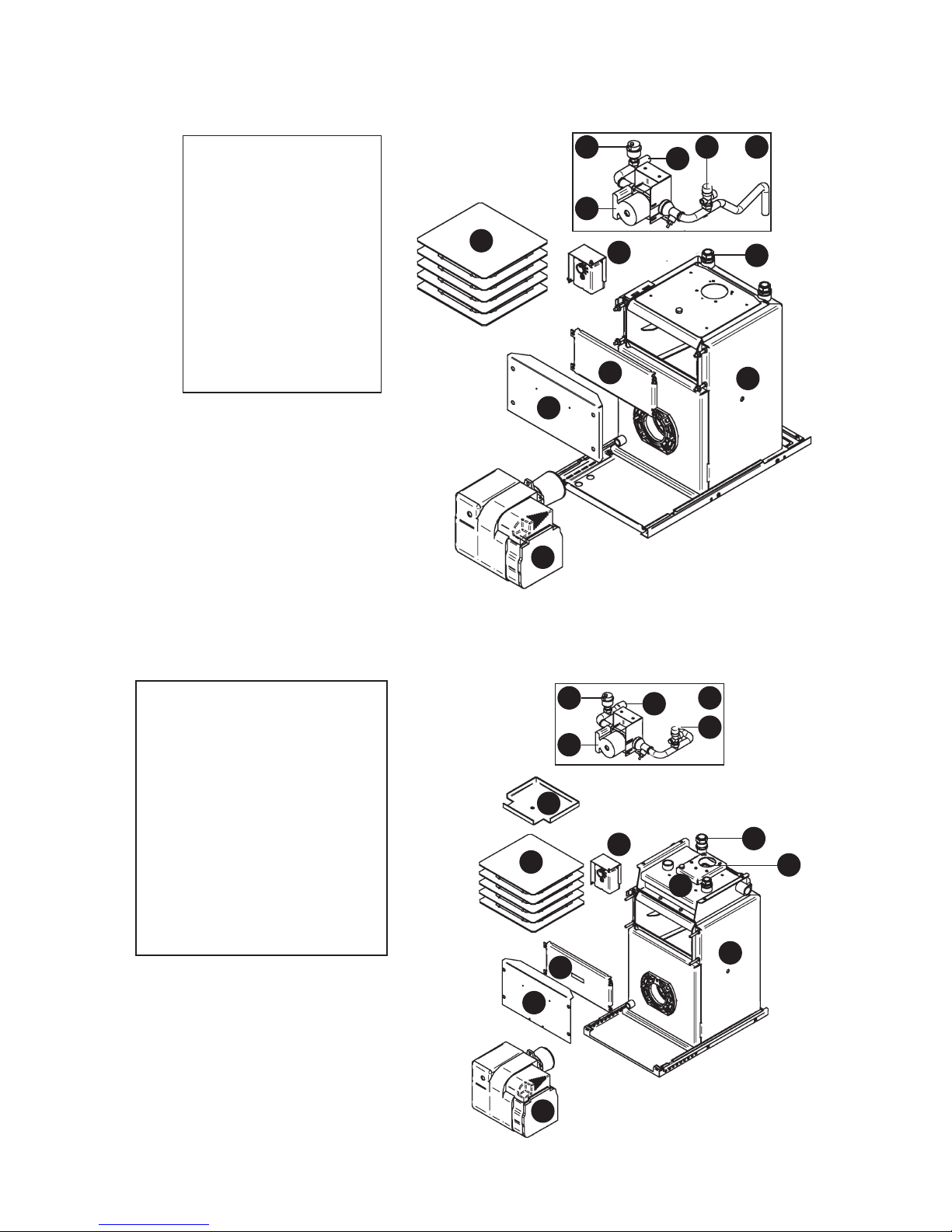
1.5.7 U-Series Utility – Pumped (UP70 & UP90) – Key Components
1. Heat Exchanger
2. Pipework Assembly
3. Pressure Relief Valve
4. Auto Air Vent
5. Circulating Pump
6. ‘Dual-Safe’ Thermostat
7. Heat Exchanger Baffles
8. Service Door
9. Service Door Cover
10. Riello RDB 2.2 Burner
11. Heating Flow
Connection
12. Heating Return
Connection
5
3
9
1. Primary Heat Exchanger
2. Secondary Heat Exchanger
3. Pipework Assembly
4. Pressure Relief Valve
5. Circulating Pump
6. Auto Air Vent
7. ‘Dual-Safe’ Thermostat
8. Secondary Exchanger
Inspection Lid
9. Primary Exchanger Baffles
10. Service Door
11. Service Door Cover
12. Riello RDB 2.2 Burner
13. Flue Opening
14. Heating Flow Connection
15. Heating Return Connection
1
8
7
5
2
6 3
15
1.5.8 U-Series Utility – Pumped (UP120) – Key Components
14
4
9
10
11
12
12
13
Page 13
Page 11
1.5.9 U-Series Utility – System (US70 & US90) – Key Components
1. Pumped (UP)
Boiler Assembly
2. System Kit (SK1)
3. Pressure Gauge
4. Expansion Vessel
5. Filling Loop
6. Heating Flow
Connection
7. Heating Return
Connection
4
3
5
2
1
6
7
1.5.10 U-Series Utility – Combi (UC70 & UC90) – Key Components
1. Heat Exchanger
2. Heat Store
3. Pipework Assembly
4. Plate Heat Exchanger
5. Twin Head Pump
6. Service Door
7. Service Door Cover
8. Control Panel
9. Expansion Vessel
10. Riello RDB 2.2 Burner
11. Heat Exchanger Baffles
12. Flue Ring
1
2
3
4
5
8
9
6
7
10
11
12
Page 14
Page 12
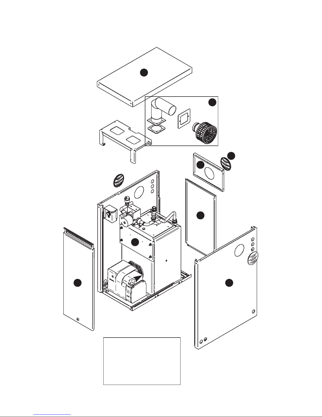
1.5.11 K-Series Kabin Pak – Casing Components
1. Boiler Assembly
2. Top Casing (removable)
3. Flue Assembly (removable)
4. Rear Flue Casing
5. Blanking Plug (removable)
6. Rear Casing (removable)
7. Side Casing
8. Front Casing (removable)
1
2
3
4
5
6
78
Page 15
Page 13
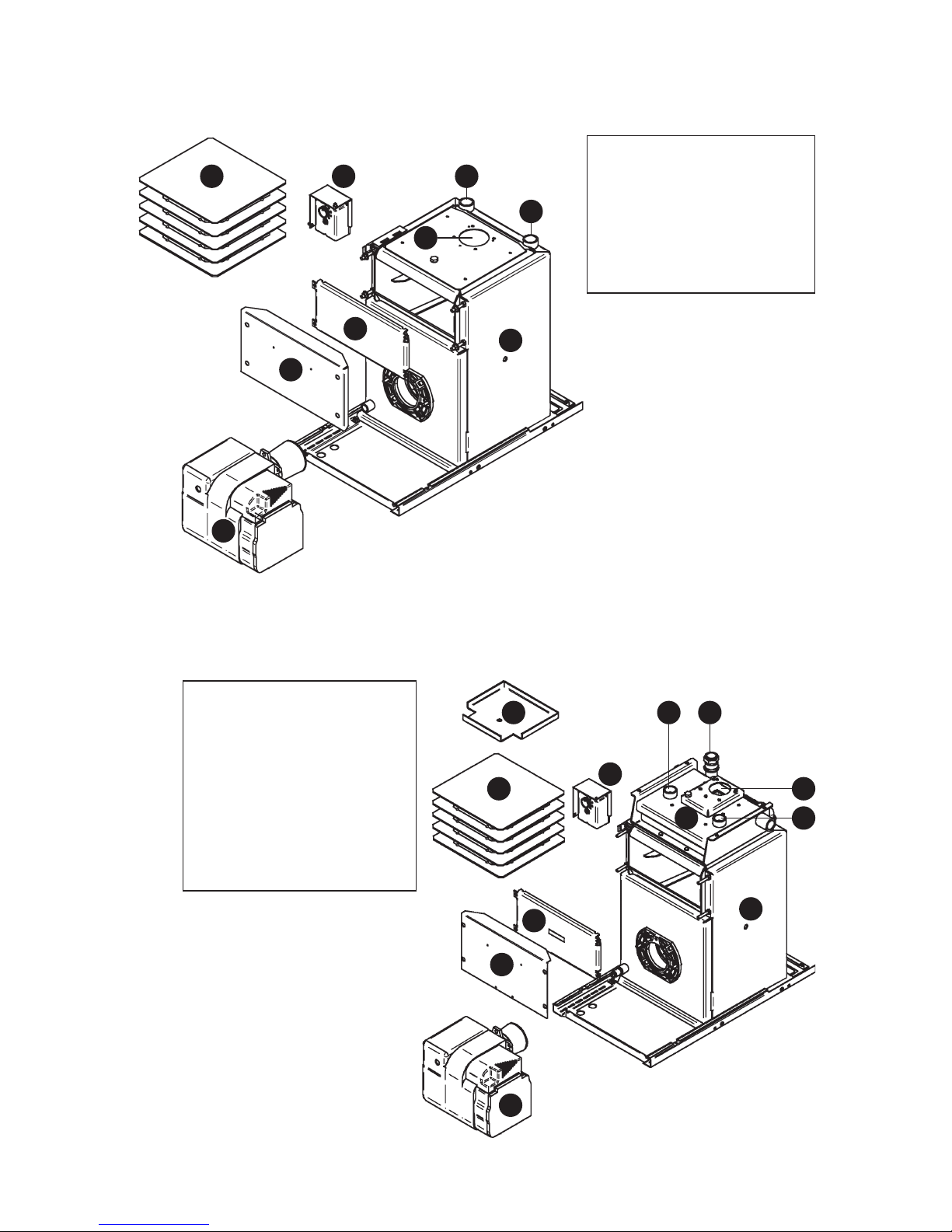
1.5.12 K-Series Kabin Pak – Pre-Wired (K70 & K90) – Key Components
1. Heat Exchanger
2. ‘Dual-Safe’ Thermostat
3. Heat Exchanger Baffles
4. Service Door
5. Service Door Cover
6. Riello RDB 2.2 Burner
7. Flue Opening
8. Heating Flow Connection
9. Heating Return Connection
1
23
5
4
6
7
8
9
1.5.13 K-Series Kabin Pak – Pre-wired (K120) – Key Components
1. Primary Heat Exchanger
2. Secondary Heat Exchanger
3. ‘Dual-Safe’ Thermostat
4. Secondary Exchanger
Inspection Lid
5. Primary Exchanger Baffles
6. Service Door
7. Service Door Cover
8. Riello RDB 2.2 Burner
9. Flue Opening
10. Heating Flow Connection x 2
11. Heating Return Connection
1
2
3
4
5
6
7
8
1110
10
9
Page 16
Page 14
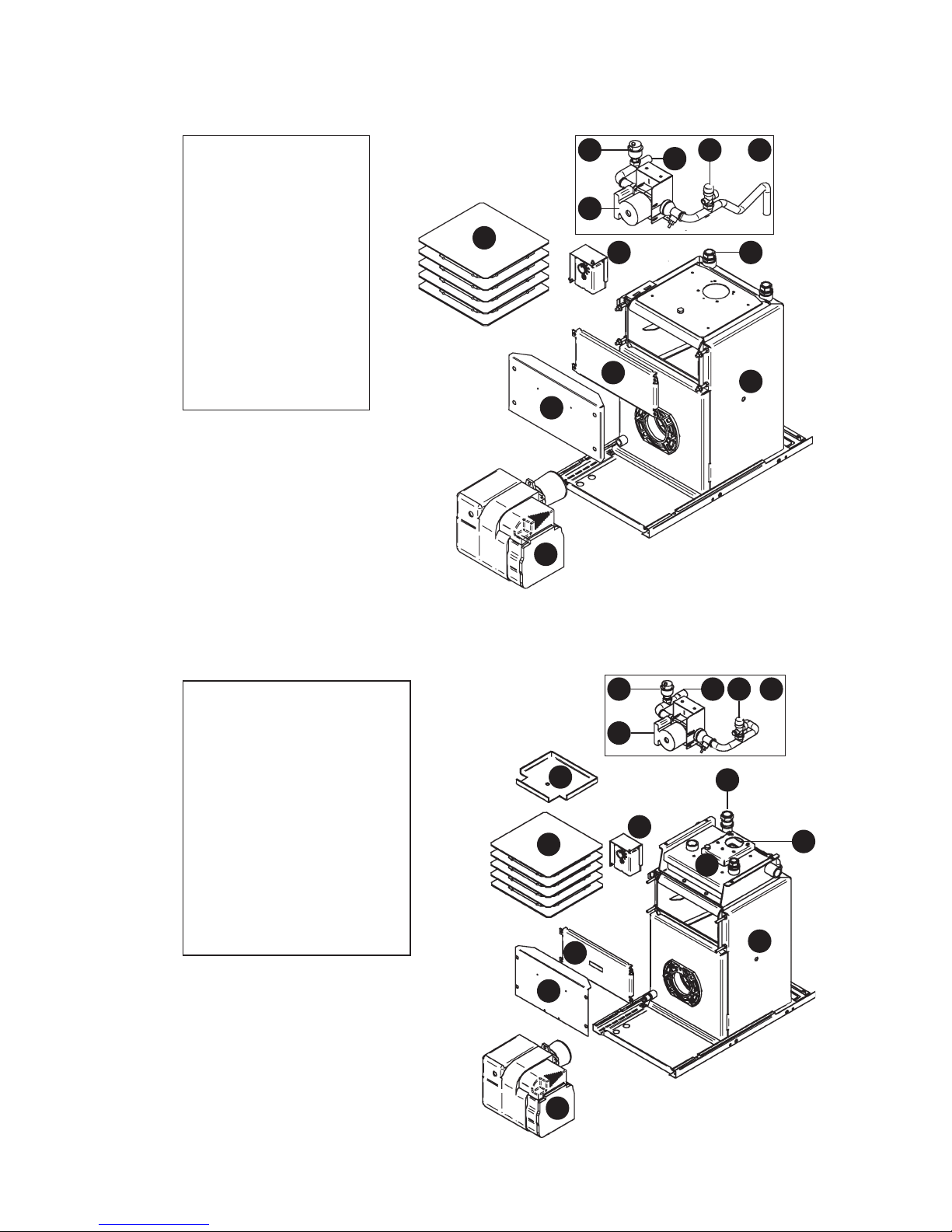
1.5.14 K-Series Kabin Pak – Pumped (KP70 & KP90) – Key Components
1
8
11
5
6
7
9
10
12
3 2
1. Heat Exchanger
2. Pipework Assembly
3. Pressure Relief Valve
4. Auto Air Vent
5. Circulating Pump
6. ‘Dual-Safe’
Thermostat
7. Heat Exchanger
Baffles
8. Service Door
9. Service Door Cover
10. Riello RDB 2.2 Burner
11. Heating Flow
Connection
12. Heating Return
Connection
1.5.15 K-Series Kabin Pak – Pumped (KP120) – Key Components
1. Primary Heat Exchanger
2. Secondary Heat Exchanger
3. Pipework Assembly
4. Pressure Relief Valve
5. Circulating Pump
6. Auto Air Vent
7. ‘Dual-Safe’ Thermostat
8. Secondary Exchanger
Inspection Lid
9. Primary Exchanger Baffles
10. Service Door
11. Service Door Cover
12. Riello RDB 2.2 Burner
13. Flue Opening
14. Heating Flow Connection
15. Heating Return Connection
4
1
2
7
8
9
10
11
12
6
5
14 4 3
15
13
Page 17
Page 15
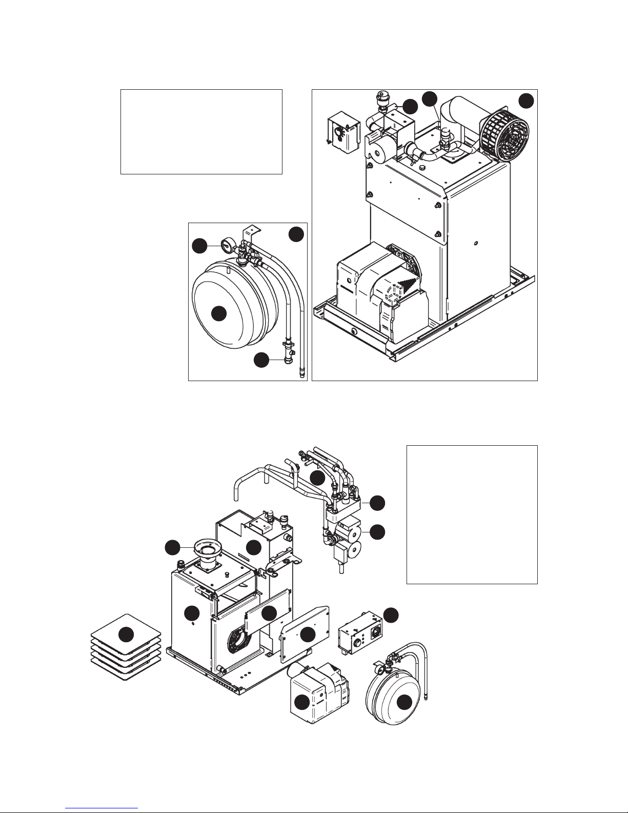
1.5.16 K-Series Kabin Pak – System (KS70 & KS90) – Key Components
1. Pumped (KP) Boiler Assembly
2. System Kit (SK1)
3. Pressure Gauge
4. Expansion Vessel
5. Filling Loop
6. Heating Flow Connection
7. Heating Return Connection
1.5.17 K-Series Kabin Pak – Combi (KC70 & KC90) – Key Components
1. Heat Exchanger
2. Heat Store
3. Pipework Assembly
4. Plate Heat Exchanger
5. Twin Head Pump
6. Service Door
7. Service Door Cover
8. Control Panel
9. Expansion Vessel
10. Riello RDB 2.2 Burner
11. Heat Exchanger Baffles
12. Flue Ring
3
5
4
2
1
6
7
1
2
3
4
5
6
7
8
910
11
12
Page 18
Page 16
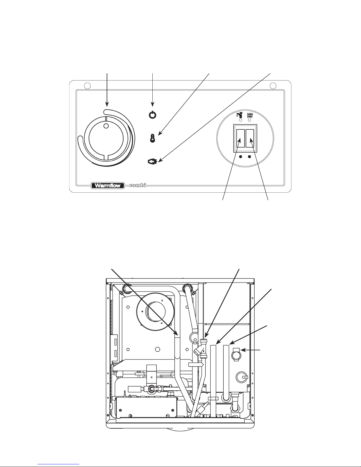
1.5.18 Combi Control Panel Layout
Control
Thermostat
Mains On
Lamp (Green)
High Limit Tripped
Lamp (Yellow)
Burner Lockout
Lamp (Red)
HW On/Off
Switch
CH On/Off
Switch
High Limit Thermostat Reset
(Underneath)
1.5.19 Combi Pipe Layout (UC & KC Models)
Central Heating
Return (22mm Copper)
Cold Water
Mains (15mm)
Domestic Hot
Water (22mm)
Central Heating
Flow (22mm)
Pressure Relief
Discharge (15mm)
Page 19

Page 17
2.0 Technical Details
2.1 Combi Sequence of Operation Flow Chart
Power
On
Timer Calling
For Heat
HW
Selected
Flow Switch
Closed
DHW Tank
Stat Satisfied
CH
Selected
CH Pump
Only Runs
Room Stat
Satisfied
Boiler Stat
Satisfied
Boiler Limit
Stat Tripped
Burner
Fires
DHW Pump
Only Runs
HW Limit
Stat Satisfied
Boiler Limit
Stat Tripped
Burner
Fires
Burner
Stops
Press
Reset Button
Press
Reset Button
Pump Overrun
Stat Satisfied
DHW Pump
Only Runs
YES
YES
YES
NO
YES
NO
YES
YES
YES
NO
NO
NO
NO
NO
NO
YES
YES
YES
YES
YES
YES NO
NO
NO
Page 20
Page 18
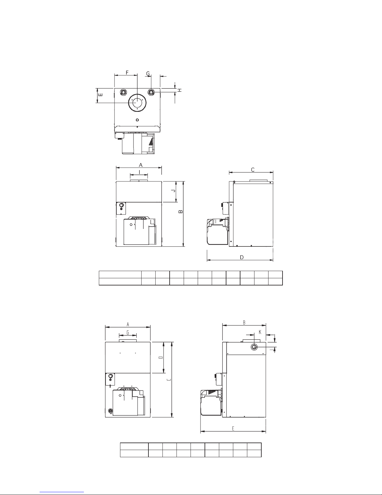
2.2 Dimensions
2.2.1 B-Series Boilerhouse (70 & 90 Output Models)
JHGFEDCBAMODEL
B70 / B90 / B1 396 573 383 574 127 198 78 32 183
I
152
2.2.2 B-Series Boilerhouse (120 Output Model)
KJGEDCBAMODEL
B120 397 383 662 273 575 152 42 103
Page 21
Page 19
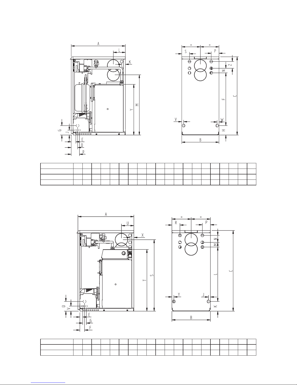
2.2.3 U-Series Utility (70 & 90 Output Non-Combi Models)
RPNMLKJHGFEDCBAMODEL
U70 & U90 600 413 865 71 51 583 104 104 54 42 134 666 50 86 91
UP70 & UP90
US70 & US90
S86V21W21Y
560Z75
600 413 865 71 51 583 104 104 54 42 134 666 50 86 91 86 21 21 560 75
600 413 865 71 51 583 104 104 54 42 134 666 50 86 91 86 21 21 560 75
2.2.4 U-Series Utility (120 Output Models)
RPNMLKJGFEDCBAMODEL
U120 600 413 865 104 30 50 40 21 104 583 50 75 86 86
UP120
S
766T662V134 54
X Y
42 21
U
600 413 865 104 30 50 40 21 104 583 50 75 86 86 766 662 134 54 42 21
Page 22
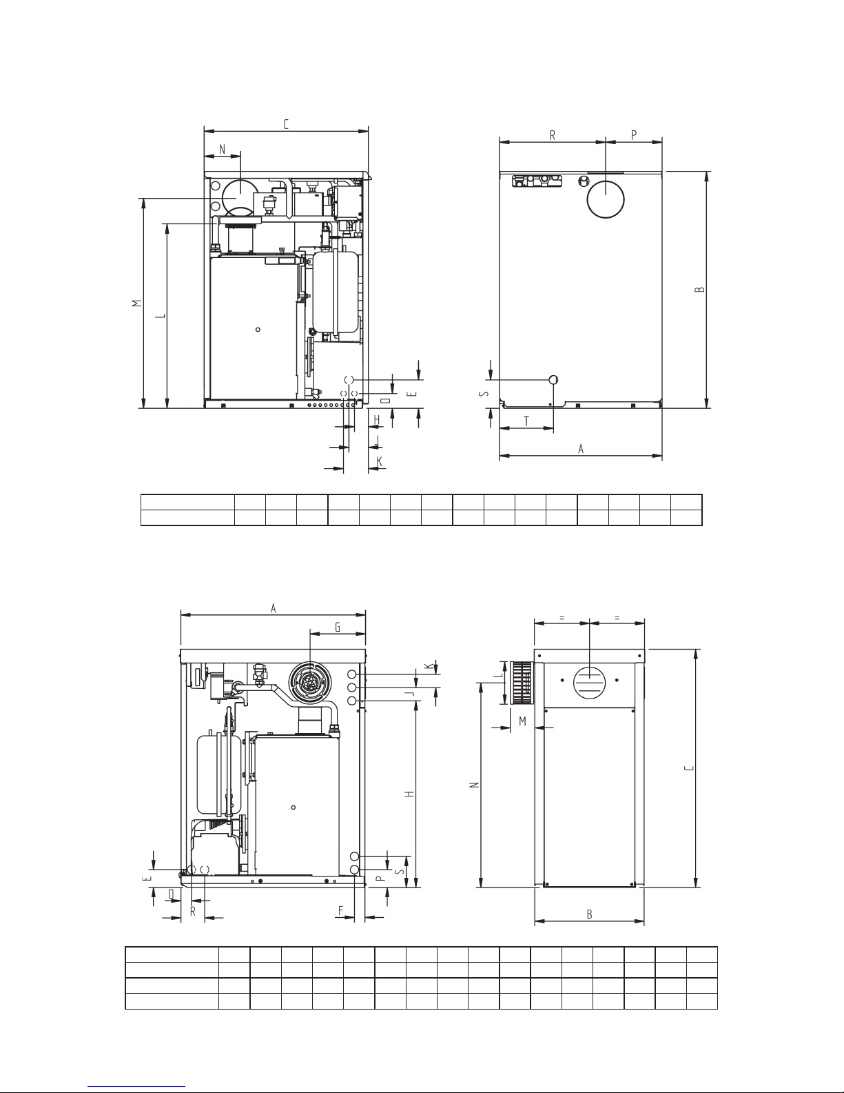
Page 20
2.2.6 K-Series Kabin Pak (K, KP & KS Models)
2.2.5 U-Series Utility (UC Models)
RPNMLKJHEDCBAMODEL
UC70 & UC90 595
S T
865 600 54 104 51 71 91 674 766 134 207 388 104 197
RPNMLKJHGFEDCBAMODEL
K70 & K90 700
S
KP70 & KP90
KS70 & KS90
413 900 40 67 40 210 705 50 50 160 93 773 67 90 117
700 413 900 40 67 40 210 705 50 50 160 93 773 67 90 117
700 413 900 40 67 40 210 705 50 50 160 93 773 67 90 117
Page 23

Page 21
2.2.7 K-Series Kabin Pak (120 Output Models)
PONMLKJHGFEDCBAMODEL
K120 700
KP120
I
413 900 40 67 117 705 50 50 67 40 773 160 210 50 90
700 413 900 40 67 117 705 50 50 67 40 773 160 210 50 90
2.2.8 K-Series Kabin Pak Base Tray (K, KP & KS Models)
Page 24
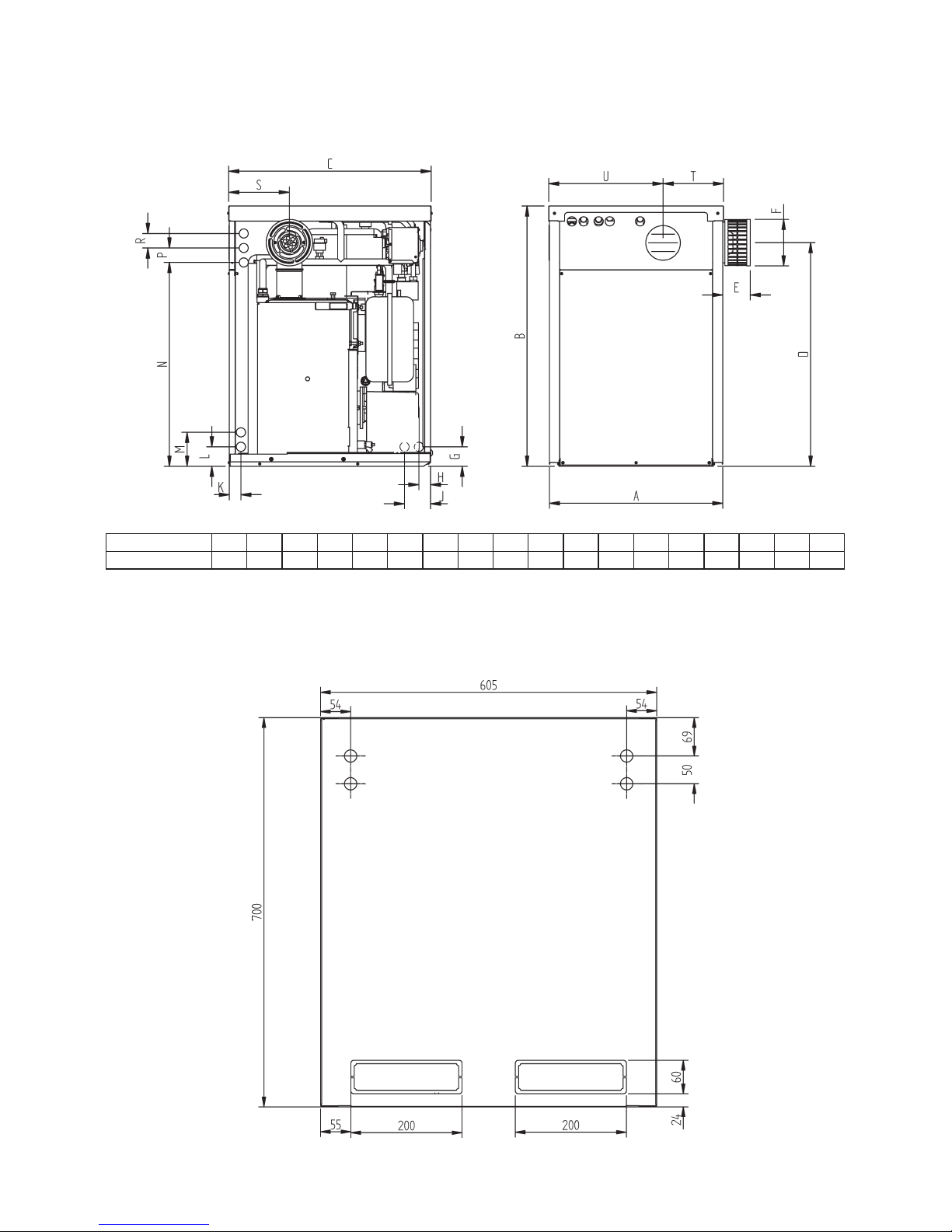
Page 22
2.2.9 K-Series Kabin Pak (KC Models)
PNMLKJHGFEDCBAMODEL R S
KC70 & KC90 600 900 700 773 95 160 67 40 90 40 67 117 705 50 50 210
T U
209 396
2.2.10 K-Series Kabin Pak Base Tray (KC Models)
Page 25
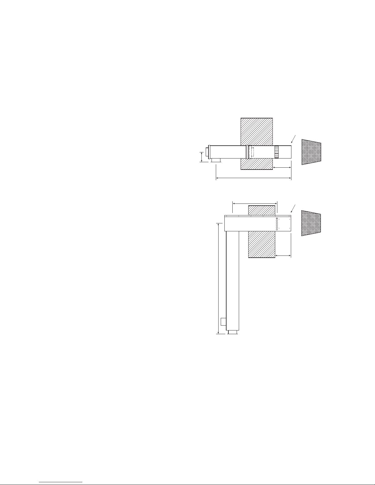
Page 23
2.3 Flue Options & Dimensions
The use of any flue system other than that supplied or recommended by the
manufacturer will invalidate the warranty.
Note that with Class D gas oil the flue MUST exhaust at more than 2m above the
surrounding ground level. The low-level flue supplied as standard with all Kabin Pak
models is NOT suitable for Class D gas oil. Alternative options are available – please
contact Warmflow.
2.3.1 ‘Easy Fit’ Low Level Balanced Flue
The horizontal dimension can be
increased up to an additional 1200mm
using a combination of long extension
pieces (600mm) and short extension
pieces (300mm).
2.3.2 ‘Easy Fit’ High Level Balanced Flue
The HLBF is available in 4 fixed
horizontal lengths which are:
Option 1 – 455mm
Option 2 – 655mm
Option 3 – 585mm
Option 4 – 785mm
Note: The ‘Easy Fit’ High Level Balanced Flue
(HLBF) can only be used with the 120
Output Models (B120, U120 & UP120)
when fired at the factory setting (0.85
gal nozzle). It CANNOT be used when
fired with a 1.00 gal nozzle or with the
0.85 gal nozzle at increased pump
pressure.
102
712 MAX
225 MAX
175 MIN
490 MIN
Ø125
225 MAX
175 MIN
1128
SEE OPTIONS
160x160
Page 26
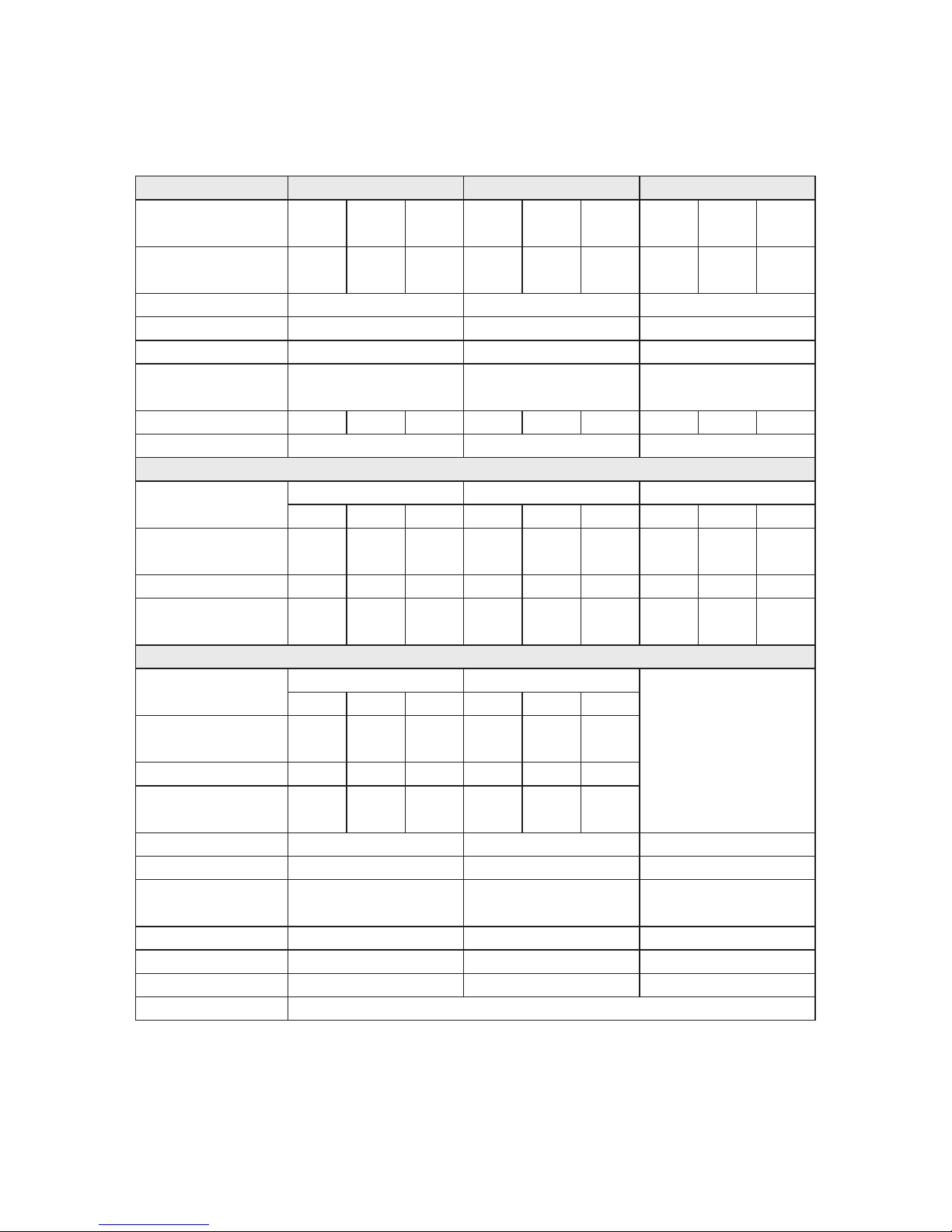
Page 24
2.4 Technical Data
2.4.1 B-Series Boilerhouse – (B)
B90B70MODEL
Nominal kW
Heat Output Btu/hr
Nominal kW
Heat Input Btu/hr
Burner
Head
Secondary Air Damper
Flue mm
Diameter in
Flue Gas Temp °C
Smoke Bacarach
14.0
48,000
17.0
58,000
20.5
70,000
20.5
70,000
22.8
78,000
26.4
90,000
15.3
52,150
18.4
62,6002275,0002275,000
24.4
83,1752895,550
RDB 2.2 15-21 RDB 2.2 21-26
T1SH T2SH
B N/A
100 or 125
4 or 5
100 or 125
4 or 5
180 190 200 200 210 215
0 0
Kerosene Settings
Nozzle make
size
Pump bar
Pressure psi
Max CO2 %
Approx Fuel litres/h
Flow Rate gals/h
Flow Connection
Return Connection
Water litres
Content gals
Boiler Weight Dry kg
Boiler Weight Wet kg
SEDBUK Efficiency %
Factory Settings
Danfoss 60°ES
0.5 0.5 0.6
Danfoss 60°ES
0.6 0.65 0.75
7.0
100
9.0
131
8.0
116
8.0
116
8.0
116
7.0
100
11.5 11.5 11.5 11.5 11.5 11.5
1.65
0.36
1.98
0.44
2.35
0.52
2.35
0.52
2.65
0.58
2.98
0.65
1” BSP Female
1” BSP Female
1” BSP Female
1” BSP Female
14
3.1
65
79
85.6
Highlighted in Bold
Gas Oil Settings
Nozzle make
size
Danfoss 60°S
— 0.4 0.5
Danfoss 60°S
0.55 0.6
Pump bar
Pressure psi
Max CO2 %
Approx Fuel litres/h
Flow Rate gals/h
—
—
12.0
174
11.0
159
11.0
159
11.0
159
— 12.0 12.0 12.0 12.0
—
—
1.72
0.38
2.30
0.51
2.53
0.56
2.76
0.61
0.5
11.0
159
12.0
2.30
0.51
14
3.1
65
79
85.6
B120
26.4
90,000
28.0
95,200
33.0
112,600
28.0
95,550
30.0
102,400
35.5
121,200
RDB 2.2 26-33
T5S
N/A
100 or 125
4 or 5
160 170
0
150
Danfoss 60°ES
0.75 0.85 1.00
7.0
100
8.0
116
8.5
124
11.5 11.5 11.5
2.98
0.65
3.40
0.75
3.70
0.82
Contact Warmflow
for diesel settings
1” BSP Female
28mm Compression
16
3.5
79
95
85.6
Note: The ‘Easy Fit’ High Level Balanced Flue (HLBF) can only be used with the B120
Model when fired at the factory setting (0.85 gal nozzle). It CANNOT be used when
fired with a 1.00 gal nozzle or with the 0.85 gal nozzle at increased pump pressure.
Page 27
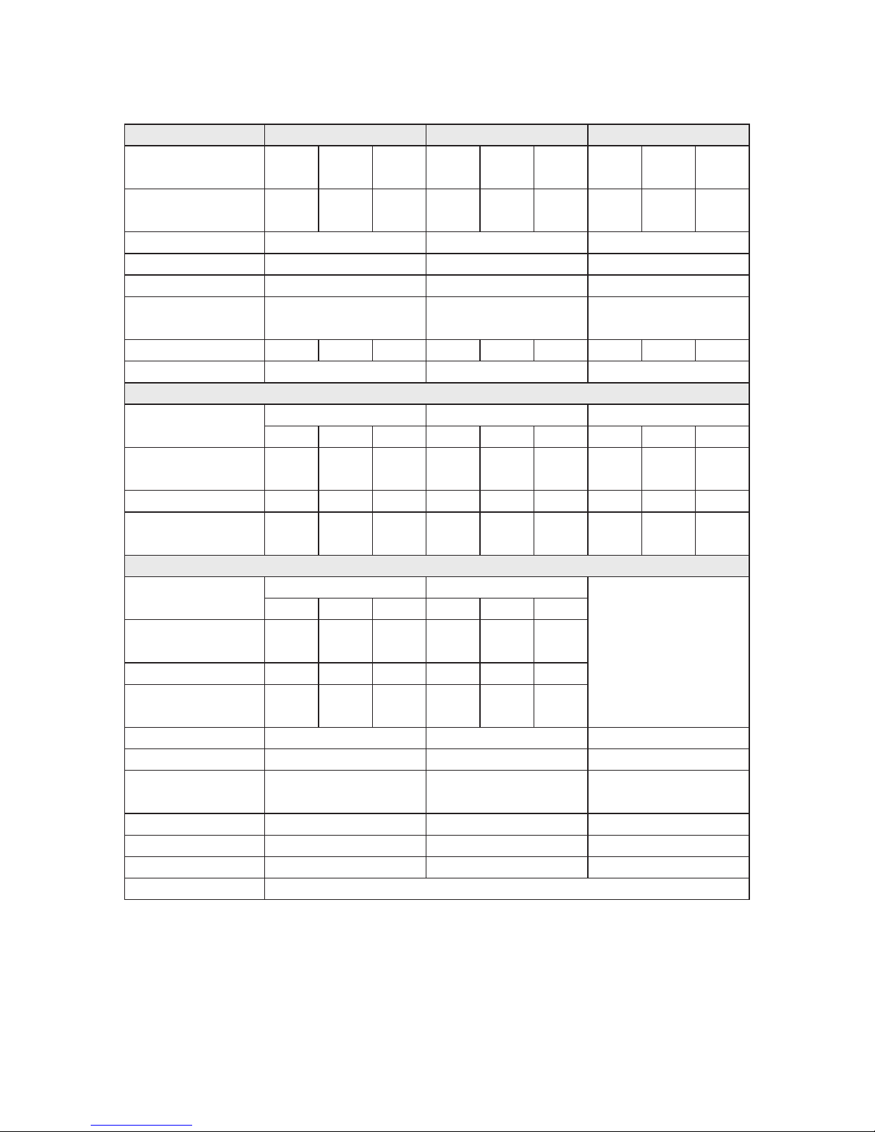
Page 25
2.4.2 U-Series Utility – Pre-Wired (U)
U90U70MODEL
Nominal kW
Heat Output Btu/hr
Nominal kW
Heat Input Btu/hr
Burner
Head
Secondary Air Damper
Flue mm
Diameter in
Flue Gas Temp °C
Smoke Bacarach
14.0
48,000
17.0
58,000
20.5
70,000
20.5
70,000
22.8
78,000
26.4
90,000
15.3
52,150
18.4
62,6002275,0002275,000
24.4
83,1752895,550
RDB 2.2 15-21 RDB 2.2 21-26
T1SH T2SH
B N/A
100 or 125
4 or 5
100 or 125
4 or 5
180 190 200 200 210 215
0 0
Nozzle make
size
Pump bar
Pressure psi
Max CO2 %
Approx Fuel litres/h
Flow Rate gals/h
Flow Connection
Return Connection
Water litres
Content gals
Boiler Weight Dry kg
Boiler Weight Wet kg
SEDBUK Efficiency %
Factory Settings
Danfoss 60°ES
0.5 0.5 0.6
Danfoss 60°ES
0.6 0.65 0.75
7.0
100
9.0
131
8.0
116
8.0
116
8.0
116
7.0
100
11.5 11.5 11.5 11.5 11.5 11.5
1.65
0.36
1.98
0.44
2.35
0.52
2.35
0.52
2.65
0.58
2.98
0.65
1” BSP Female
1” BSP Female
1” BSP Female
1” BSP Female
14
3.1
78
92
85.6
Nozzle make
size
Danfoss 60°S
— 0.4 0.5
Danfoss 60°S
0.55 0.6
Pump bar
Pressure psi
Max CO2 %
Approx Fuel litres/h
Flow Rate gals/h
—
—
12.0
174
11.0
159
11.0
159
11.0
159
— 12.0 12.0 12.0 12.0
—
—
1.72
0.38
2.30
0.51
2.53
0.56
2.76
0.61
0.5
11.0
159
12.0
2.30
0.51
14
3.1
78
92
85.6
Kerosene Settings
Highlighted in Bold
Gas Oil Settings
U120
26.4
90,000
28.0
95,200
33.0
112,600
28.0
95,550
30.0
102,400
35.5
121,200
RDB 2.2 26-33
T5S
N/A
100 or 125
4 or 5
160 170
0
150
Danfoss 60°ES
0.75 0.85 1.00
7.0
100
8.0
116
8.5
124
11.5 11.5 11.5
2.98
0.65
3.40
0.75
3.70
0.82
Contact Warmflow
for diesel settings
1” BSP Female
28mm Compression
16
3.5
92
108
85.6
Note: The ‘Easy Fit’ High Level Balanced Flue (HLBF) can only be used with the U120
Model when fired at the factory setting (0.85 gal nozzle). It CANNOT be used when
fired with a 1.00 gal nozzle or with the 0.85 gal nozzle at increased pump pressure.
Page 28
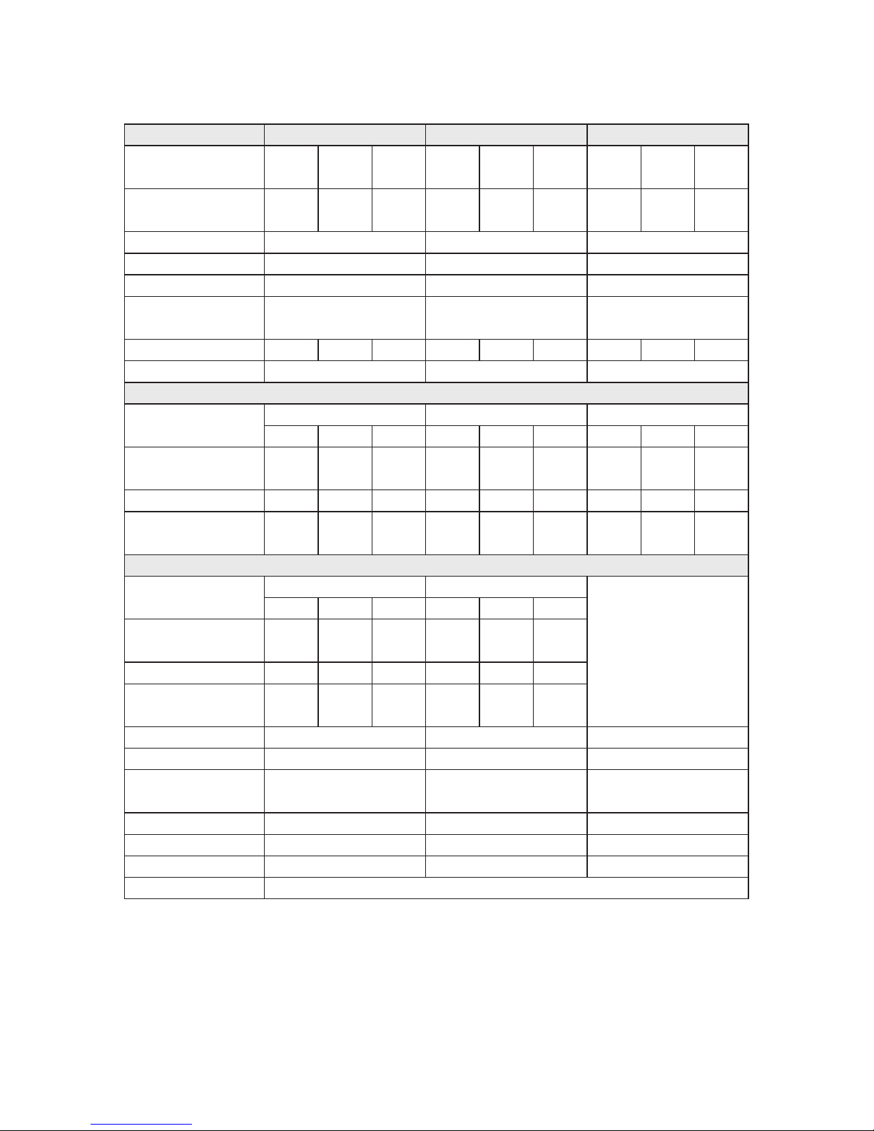
Page 26
2.4.3 U-Series Utility – Pumped (UP)
UP90UP70MODEL
Nominal kW
Heat Output Btu/hr
Nominal kW
Heat Input Btu/hr
Burner
Head
Secondary Air Damper
Flue mm
Diameter in
Flue Gas Temp °C
Smoke Bacarach
14.0
48,000
17.0
58,000
20.5
70,000
20.5
70,000
22.8
78,000
26.4
90,000
15.3
52,150
18.4
62,6002275,0002275,000
24.4
83,1752895,550
RDB 2.2 15-21 RDB 2.2 21-26
T1SH T2SH
B N/A
100 or 125
4 or 5
100 or 125
4 or 5
180 190 200 200 210 215
0 0
Nozzle make
size
Pump bar
Pressure psi
Max CO2 %
Approx Fuel litres/h
Flow Rate gals/h
Flow Connection
Return Connection
Water litres
Content gals
Boiler Weight Dry kg
Boiler Weight Wet kg
SEDBUK Efficiency %
Factory Settings
Danfoss 60°ES
0.5 0.5 0.6
Danfoss 60°ES
0.6 0.65 0.75
7.0
100
9.0
131
8.0
116
8.0
116
8.0
116
7.0
100
11.5 11.5 11.5 11.5 11.5 11.5
1.65
0.36
1.98
0.44
2.35
0.52
2.35
0.52
2.65
0.58
2.98
0.65
22mm Copper
1” BSP Female
22mm Copper
1” BSP Female
14
3.1
78
92
85.6
Nozzle make
size
Danfoss 60°S
— 0.4 0.5
Danfoss 60°S
0.55 0.6
Pump bar
Pressure psi
Max CO2 %
Approx Fuel litres/h
Flow Rate gals/h
—
—
12.0
174
11.0
159
11.0
159
11.0
159
— 12.0 12.0 12.0 12.0
—
—
1.72
0.38
2.30
0.51
2.53
0.56
2.76
0.61
0.5
11.0
159
12.0
2.30
0.51
14
3.1
78
92
85.6
Kerosene Settings
Highlighted in Bold
Gas Oil Settings
UP120
26.4
90,000
28.0
95,200
33.0
112,600
28.0
95,550
30.0
102,400
35.5
121,200
RDB 2.2 26-33
T5S
N/A
100 or 125
4 or 5
160 170
0
150
Danfoss 60°ES
0.75 0.85 1.00
7.0
100
8.0
116
8.5
124
11.5 11.5 11.5
2.98
0.65
3.40
0.75
3.70
0.82
Contact Warmflow
for diesel settings
28mm Compression
28mm Compression
16
3.5
92
108
85.6
Note: The ‘Easy Fit’ High Level Balanced Flue (HLBF) can only be used with the UP120
Model when fired at the factory setting (0.85 gal nozzle). It CANNOT be used when
fired with a 1.00 gal nozzle or with the 0.85 gal nozzle at increased pump pressure.
Page 29
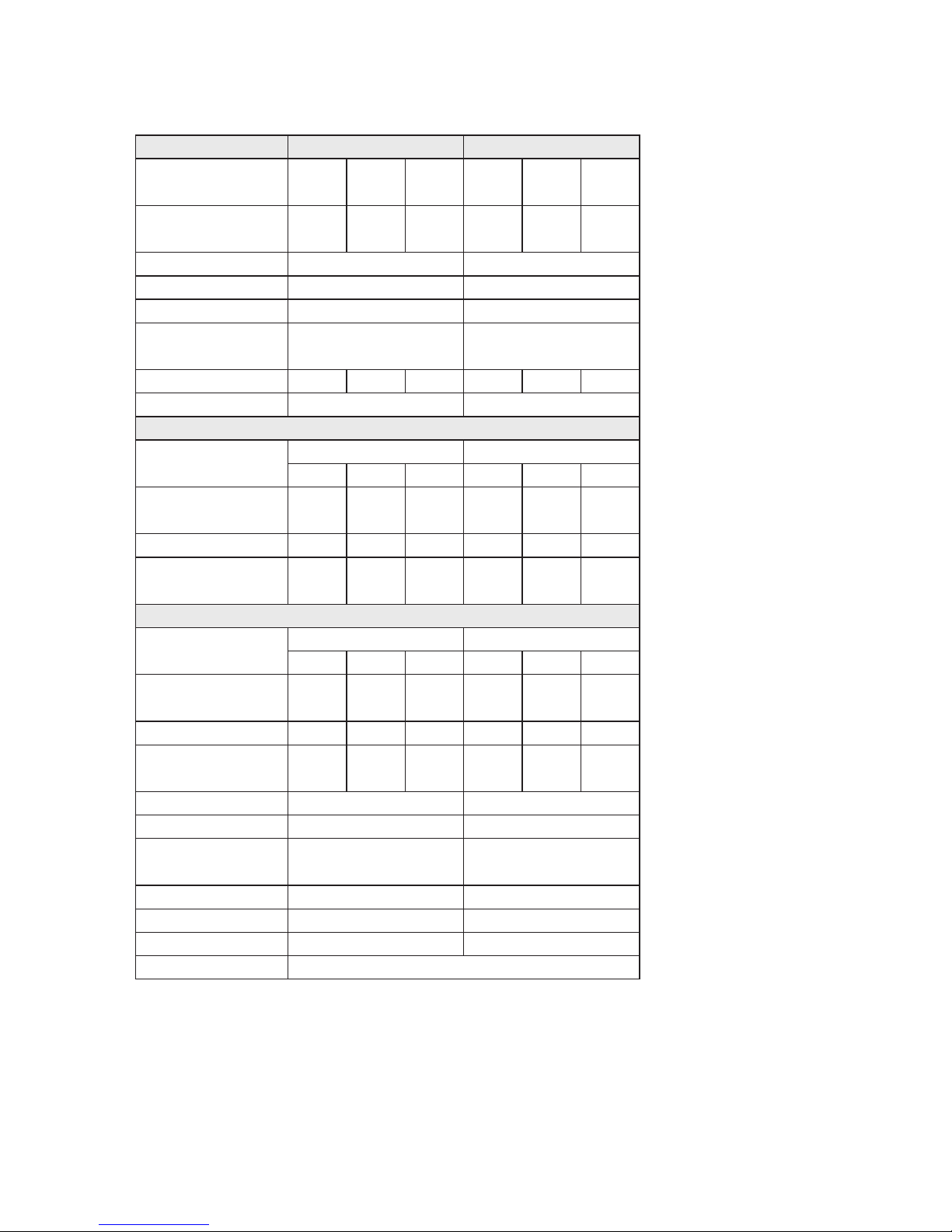
Page 27
2.4.4 U-Series Utility – System (US)
US90US70MODEL
Nominal kW
Heat Output Btu/hr
Nominal kW
Heat Input Btu/hr
Burner
Head
Secondary Air Damper
Flue mm
Diameter in
Flue Gas Temp °C
Smoke Bacarach
14.0
48,000
17.0
58,000
20.5
70,000
20.5
70,000
22.8
78,000
26.4
90,000
15.3
52,150
18.4
62,6002275,0002275,000
24.4
83,1752895,550
RDB 2.2 15-21 RDB 2.2 21-26
T1SH T2SH
B N/A
100 or 125
4 or 5
100 or 125
4 or 5
180 190 200 200 210 215
0 0
Kerosene Settings
Nozzle make
size
Pump bar
Pressure psi
Max CO2 %
Approx Fuel litres/h
Flow Rate gals/h
Flow Connection
Return Connection
Water litres
Content gals
Boiler Weight Dry kg
Boiler Weight Wet kg
SEDBUK Efficiency %
Factory Settings
Danfoss 60°ES
0.5 0.5 0.6
Danfoss 60°ES
0.6 0.65 0.75
7.0
100
9.0
131
8.0
116
8.0
116
8.0
116
7.0
100
11.5 11.5 11.5 11.5 11.5 11.5
1.65
0.36
1.98
0.44
2.35
0.52
2.35
0.52
2.65
0.58
2.98
0.65
22mm Copper
1” BSP Female
22mm Copper
1” BSP Female
14
3.1
78
92
85.6
Gas Oil Settings
Nozzle make
size
Danfoss 60°S
— 0.4 0.5
Danfoss 60°S
0.55 0.6
Pump bar
Pressure psi
Max CO2 %
Approx Fuel litres/h
Flow Rate gals/h
—
—
12.0
174
11.0
159
11.0
159
11.0
159
— 12.0 12.0 12.0 12.0
—
—
1.72
0.38
2.30
0.51
2.53
0.56
2.76
0.61
0.5
11.0
159
12.0
2.30
0.51
14
3.1
78
92
85.6
Highlighted in Bold
Page 30
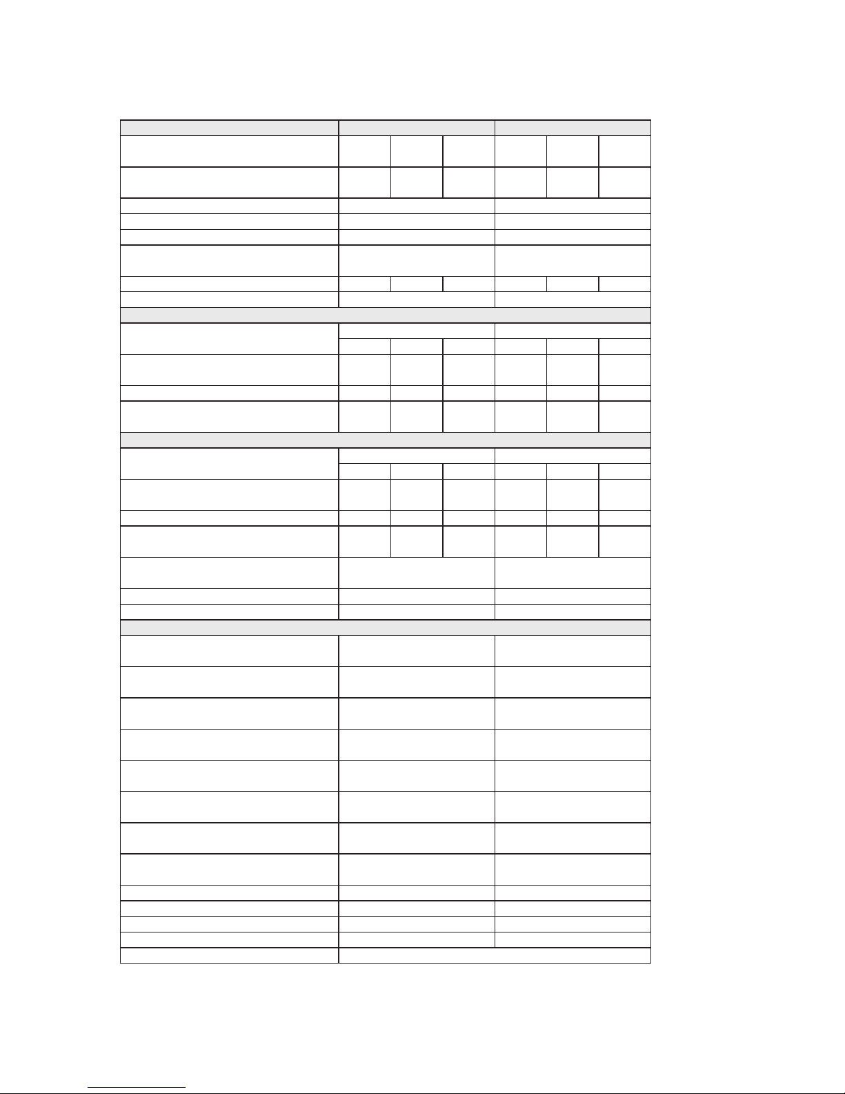
Page 28
2.4.5 U-Series Utility – Combi (UC)
UC90UC70MODEL
Nominal kW
Heat Output Btu/hr
Nominal kW
Heat Input Btu/hr
Burner
Head
Secondary Air Damper
Flue mm
Diameter in
Flue Gas Temp °C
Smoke Bacarach
14.0
48,000
17.0
58,000
20.5
70,000
20.5
70,000
22.8
78,000
26.4
90,000
15.3
52,150
18.4
62,6002275,0002275,000
24.4
83,1752895,550
RDB 2.2 15-21 RDB 2.2 21-26
T1SH T2SH
B N/A
100 or 125
4 or 5
100 or 125
4 or 5
180 190 200 200 210 215
0 0
Kerosene Settings
Nozzle make
size
Oil Pump bar
Pressure psi
Max CO2 %
Approx Fuel litres/h
Flow Rate gals/h
Flow Connection
Return Connection
Water litres
Content gals
Boiler Weight Dry kg
Boiler Weight Wet kg
SEDBUK Efficiency %
Factory Settings
Danfoss 60°ES
0.5 0.5 0.6
Danfoss 60°ES
0.6 0.65 0.75
7.0
100
9.0
131
8.0
116
8.0
116
8.0
116
7.0
100
11.5 11.5 11.5 11.5 11.5 11.5
1.65
0.36
1.98
0.44
2.35
0.52
2.35
0.52
2.65
0.58
2.98
0.65
22mm Copper 22mm Copper
70
15.4
128
198
82.8 82.8
Highlighted in Bold
70
15.4
128
198
Domestic Hot Water (DHW) Production
Minimum Inlet Dynamic Pressure bar
for Maximum DHW Flow Rate psi
Maximum Achievable
DHW Flow Rate
Maximum Recommended litres/m
DHW Flow Rate gals/m
Factory Set litres/m
DHW Flow Rate gals/m
Minimum litres/m
DHW Flow Rate gals/m
DHW Temperature Rise
(at Maximum Output)
Pressure Relief bar
psi
Cold Water Mains
Inlet Connection
DHW Outlet Connection
1.8
26
1.8
26
Unrestricted Unrestricted
18
4.0
24
5.3
18
4.0
18
4.0
2.5
0.55
2.5
0.55
32°C @ 18 litres/min
for 120 litre draw-off
32°C @ 24 litres/min
for 120 litre draw-off
3
43.5
3
43.5
Minimum 15mm
Unrestricted
Minimum 15mm
Unrestricted
22mm Copper 22mm Copper
22mm Copper 22mm Copper
Gas Oil Settings
Nozzle make
size
Oil Pump bar
Pressure psi
Max CO2 %
Approx Fuel litres/h
Flow Rate gals/h
Danfoss 60°S
— 0.4 0.5
Danfoss 60°S
0.65 0.6
—
—
12.0
174
11.0
159
8.0
116
11.0
159
— 12.0 12.0 12.0 12.0
—
—
1.72
0.38
2.30
0.51
2.65
0.58
2.76
0.61
0.5
11.0
159
12.0
2.30
0.51
Page 31
Page 29
2.4.6 K-Series Kabin Pak – Pre-Wired (K)
K90K70MODEL
Nominal kW
Heat Output Btu/hr
Nominal kW
Heat Input Btu/hr
Burner
Head
Secondary Air Damper
Flue mm
Diameter in
Flue Gas Temp °C
Smoke Bacarach
14.0
48,000
17.0
58,000
20.5
70,000
20.5
70,000
22.8
78,000
26.4
90,000
15.3
52,150
18.4
62,6002275,0002275,000
24.4
83,1752895,550
RDB 2.2 15-21 RDB 2.2 21-26
T1SH T2SH
B N/A
100 or 125
4 or 5
100 or 125
4 or 5
180 190 200 200 210 215
0 0
Nozzle make
size
Pump bar
Pressure psi
Max CO2 %
Approx Fuel litres/h
Flow Rate gals/h
Flow Connection
Return Connection
Water litres
Content gals
Boiler Weight Dry kg
Boiler Weight Wet kg
SEDBUK Efficiency %
Factory Settings
Danfoss 60°ES
0.5 0.5 0.6
Danfoss 60°ES
0.6 0.65 0.75
7.0
100
9.0
131
8.0
116
8.0
116
8.0
116
7.0
100
11.5 11.5 11.5 11.5 11.5 11.5
1.65
0.36
1.98
0.44
2.35
0.52
2.35
0.52
2.65
0.58
2.98
0.65
1” BSP Female
1” BSP Female
1” BSP Female
1” BSP Female
14
3.1
78
92
85.6
Nozzle make
size
Danfoss 60°S
— 0.4 0.5
Danfoss 60°S
0.55 0.6
Pump bar
Pressure psi
Max CO2 %
Approx Fuel litres/h
Flow Rate gals/h
—
—
12.0
174
11.0
159
11.0
159
11.0
159
— 12.0 12.0 12.0 12.0
—
—
1.72
0.38
2.30
0.51
2.53
0.56
2.76
0.61
0.5
11.0
159
12.0
2.30
0.51
14
3.1
78
92
85.6
Kerosene Settings
Highlighted in Bold
Gas Oil Settings (see note below)
K120
26.4
90,000
28.0
95,200
33.0
112,600
28.0
95,550
30.0
102,400
35.5
121,200
RDB 2.2 26-33
T5S
N/A
100 or 125
4 or 5
160 170
0
150
Danfoss 60°ES
0.75 0.85 1.00
7.0
100
8.0
116
8.5
124
11.5 11.5 11.5
2.98
0.65
3.40
0.75
3.70
0.82
Contact Warmflow
for diesel settings.
Also, see note below.
1” BSP Female
28mm Compression
16
3.5
92
108
85.6
Note: With Class D gas oil the flue MUST exhaust at more than 2m above the surrounding
ground level. The low-level flue supplied as standard with all Kabin Pak models is
NOT suitable for Class D gas oil. Alternative options are available – please contact
Warmflow.
Page 32
Page 30
2.4.7 K-Series Kabin Pak – Pumped (KP)
KP90KP70MODEL
Nominal kW
Heat Output Btu/hr
Nominal kW
Heat Input Btu/hr
Burner
Head
Secondary Air Damper
Flue mm
Diameter in
Flue Gas Temp °C
Smoke Bacarach
14.0
48,000
17.0
58,000
20.5
70,000
20.5
70,000
22.8
78,000
26.4
90,000
15.3
52,150
18.4
62,6002275,0002275,000
24.4
83,1752895,550
RDB 2.2 15-21 RDB 2.2 21-26
T1SH T2SH
B N/A
100 or 125
4 or 5
100 or 125
4 or 5
180 190 200 200 210 215
0 0
Nozzle make
size
Pump bar
Pressure psi
Max CO2 %
Approx Fuel litres/h
Flow Rate gals/h
Flow Connection
Return Connection
Water litres
Content gals
Boiler Weight Dry kg
Boiler Weight Wet kg
SEDBUK Efficiency %
Factory Settings
Danfoss 60°ES
0.5 0.5 0.6
Danfoss 60°ES
0.6 0.65 0.75
7.0
100
9.0
131
8.0
116
8.0
116
8.0
116
7.0
100
11.5 11.5 11.5 11.5 11.5 11.5
1.65
0.36
1.98
0.44
2.35
0.52
2.35
0.52
2.65
0.58
2.98
0.65
22mm Copper 22mm Copper
14
3.1
78
92
85.6
Nozzle make
size
Danfoss 60°S
— 0.4 0.5
Danfoss 60°S
0.55 0.6
Pump bar
Pressure psi
Max CO2 %
Approx Fuel litres/h
Flow Rate gals/h
—
—
12.0
174
11.0
159
11.0
159
11.0
159
— 12.0 12.0 12.0 12.0
—
—
1.72
0.38
2.30
0.51
2.53
0.56
2.76
0.61
0.5
11.0
159
12.0
2.30
0.51
14
3.1
78
92
85.6
22mm Compression 22mm Compression
Kerosene Settings
Highlighted in Bold
Gas Oil Settings (see note below)
KP120
26.4
90,000
28.0
95,200
33.0
112,600
28.0
95,550
30.0
102,400
35.5
121,200
RDB 2.2 26-33
T5S
N/A
100 or 125
4 or 5
160 170
0
150
Danfoss 60°ES
0.75 0.85 1.00
7.0
100
8.0
116
8.5
124
11.5 11.5 11.5
2.98
0.65
3.40
0.75
3.70
0.82
Contact Warmflow
for diesel settings.
Also, see note below.
28mm Compression
28mm Compression
16
3.5
92
108
85.6
Note: With Class D gas oil the flue MUST exhaust at more than 2m above the surrounding
ground level. The low-level flue supplied as standard with all Kabin Pak models is
NOT suitable for Class D gas oil. Alternative options are available – please contact
Warmflow.
Page 33
Page 31
2.4.8 K-Series Kabin Pak – System (KS)
KS90KS70MODEL
Nominal kW
Heat Output Btu/hr
Nominal kW
Heat Input Btu/hr
Burner
Head
Secondary Air Damper
Flue mm
Diameter in
Flue Gas Temp °C
Smoke Bacarach
14.0
48,000
17.0
58,000
20.5
70,000
20.5
70,000
22.8
78,000
26.4
90,000
15.3
52,150
18.4
62,6002275,0002275,000
24.4
83,1752895,550
RDB 2.2 15-21 RDB 2.2 21-26
T1SH T2SH
B N/A
100 or 125
4 or 5
100 or 125
4 or 5
180 190 200 200 210 215
0 0
Kerosene Settings
Nozzle make
size
Pump bar
Pressure psi
Max CO2 %
Approx Fuel litres/h
Flow Rate gals/h
Flow Connection
Return Connection
Water litres
Content gals
Boiler Weight Dry kg
Boiler Weight Wet kg
SEDBUK Efficiency %
Factory Settings
Danfoss 60°ES
0.5 0.5 0.6
Danfoss 60°ES
0.6 0.65 0.75
7.0
100
9.0
131
8.0
116
8.0
116
8.0
116
7.0
100
11.5 11.5 11.5 11.5 11.5 11.5
1.65
0.36
1.98
0.44
2.35
0.52
2.35
0.52
2.65
0.58
2.98
0.65
22mm Copper
22mm Compression
22mm Copper
22mm Compression
14
3.1
78
92
85.6
Gas Oil Settings (see note below)
Nozzle make
size
Danfoss 60°S
— 0.4 0.5
Danfoss 60°S
0.65 0.6
Pump bar
Pressure psi
Max CO2 %
Approx Fuel litres/h
Flow Rate gals/h
—
—
12.0
174
11.0
159
8.0
116
11.0
159
— 12.0 12.0 12.0 12.0
—
—
1.72
0.38
2.30
0.51
2.65
0.58
2.76
0.61
0.5
11.0
159
12.0
2.30
0.51
14
3.1
78
92
85.6
Highlighted in Bold
Note: With Class D gas oil the flue MUST exhaust at more than 2m above the surrounding
ground level. The low-level flue supplied as standard with all Kabin Pak models is
NOT suitable for Class D gas oil. Alternative options are available – please contact
Warmflow.
Page 34
Page 32
2.4.9 K-Series Kabin Pak – Combi (KC)
KC90KC70MODEL
Nominal kW
Heat Output Btu/hr
Nominal kW
Heat Input Btu/hr
Burner
Head
Secondary Air Damper
Flue mm
Diameter in
Flue Gas Temp °C
Smoke Bacarach
14.0
48,000
17.0
58,000
20.5
70,000
20.5
70,000
22.8
78,000
26.4
90,000
15.3
52,150
18.4
62,6002275,0002275,000
24.4
83,1752895,550
RDB 2.2 15-21 RDB 2.2 21-26
T1SH T2SH
B N/A
100 or 125
4 or 5
100 or 125
4 or 5
180 190 200 200 210 215
0 0
Kerosene Settings
Nozzle make
size
Oil Pump bar
Pressure psi
Max CO2 %
Approx Fuel litres/h
Flow Rate gals/h
Flow Connection
Return Connection
Water litres
Content gals
Boiler Weight Dry kg
Boiler Weight Wet kg
SEDBUK Efficiency %
Factory Settings
Danfoss 60°ES
0.5 0.5 0.6
Danfoss 60°ES
0.6 0.65 0.75
7.0
100
9.0
131
8.0
116
8.0
116
8.0
116
7.0
100
11.5 11.5 11.5 11.5 11.5 11.5
1.65
0.36
1.98
0.44
2.35
0.52
2.35
0.52
2.65
0.58
2.98
0.65
22mm Copper 22mm Copper
70
15.4
128
198
82.8 82.8
Highlighted in Bold
70
15.4
128
198
Domestic Hot Water (DHW) Production
Minimum Inlet Dynamic Pressure bar
for Maximum DHW Flow Rate psi
Maximum Achievable
DHW Flow Rate
Maximum Recommended litres/m
DHW Flow Rate gals/m
Factory Set litres/m
DHW Flow Rate gals/m
Minimum litres/m
DHW Flow Rate gals/m
DHW Temperature Rise
(at Maximum Output)
Pressure Relief bar
psi
Cold Water Mains
Inlet Connection
DHW Outlet Connection
1.8
26
1.8
26
Unrestricted Unrestricted
18
4.0
24
5.3
18
4.0
18
4.0
2.5
0.55
2.5
0.55
32°C @ 18 litres/min
for 120 litre draw-off
32°C @ 24 litres/min
for 120 litre draw-off
3
43.5
3
43.5
Minimum 15mm
Unrestricted
Minimum 15mm
Unrestricted
22mm Copper 22mm Copper
22mm Copper 22mm Copper
Gas Oil Settings (see note below)
Nozzle make
size
Oil Pump bar
Pressure psi
Max CO2 %
Approx Fuel litres/h
Flow Rate gals/h
Danfoss 60°S
— 0.4 0.5
Danfoss 60°S
0.65 0.6
—
—
12.0
174
11.0
159
8.0
116
11.0
159
— 12.0 12.0 12.0 12.0
—
—
1.72
0.38
2.30
0.51
2.65
0.58
2.76
0.61
0.5
11.0
159
12.0
2.30
0.51
Note: With Class D gas oil the flue MUST exhaust at more than 2m above the surrounding
ground level. The low-level flue supplied as standard with all Kabin Pak models is
NOT suitable for Class D gas oil. Alternative options are available – please contact
Warmflow.
Page 35
Page 33
3.0 Electricity Supply & Wiring Details
220 – 240V. 1PH, 50 Hz
The boiler/burner and other external electrical equipment should be wired with heat
resistant cable via a fused double pole isolating switch which should be fitted with a
5 amp fuse.
The appliance must be effectively earthed and all external wiring should comply with
current IEE Regulations.
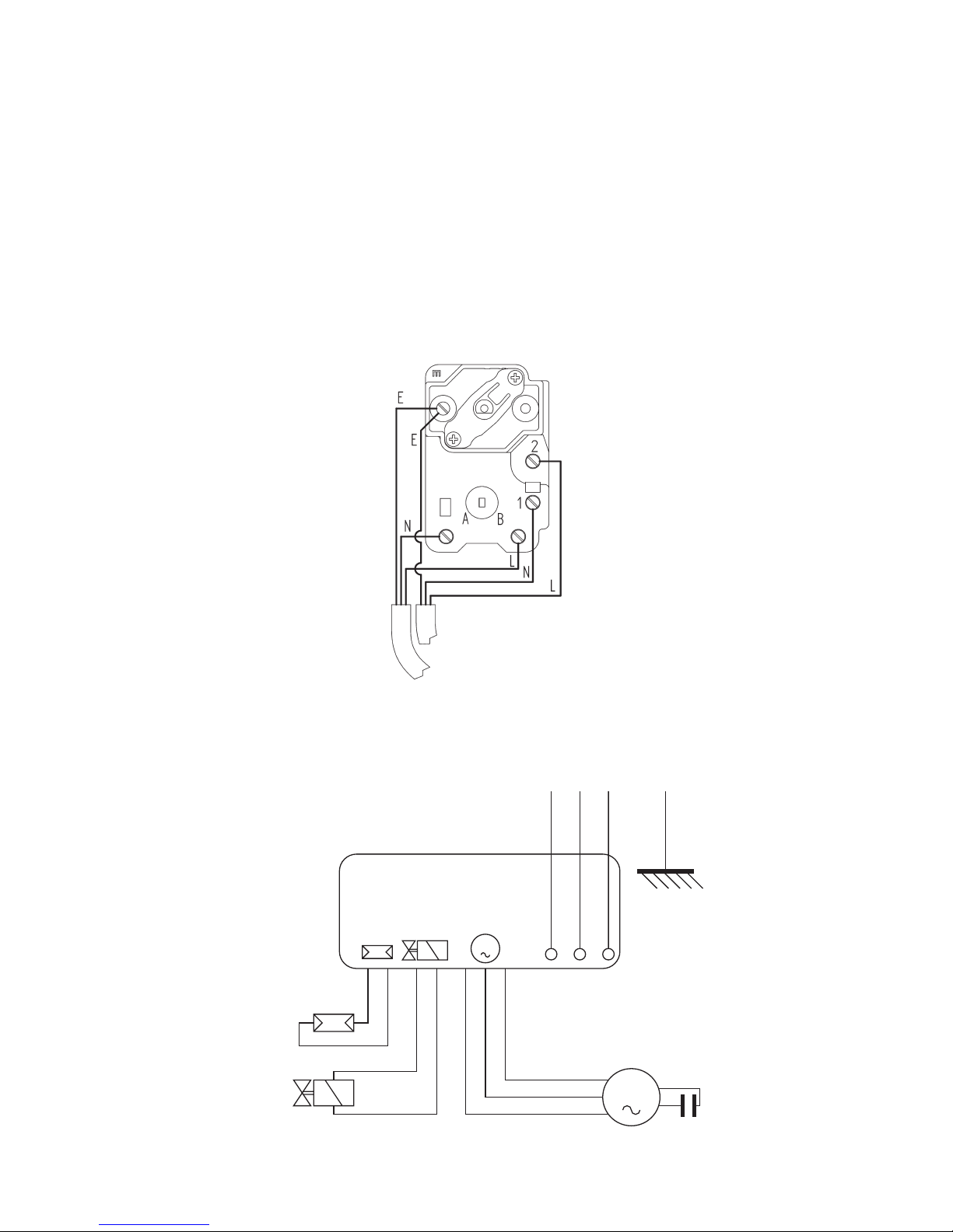
3.1 Dual-Safe Thermostat (Non-Combi Boilers)
Warning: Do not fit any other wires or loop wires to this stat as this will bypass the
thermostats.
3.2 RDB Burner Control Box
CONTROL BOX
535SE/LD
M
M
Oil Valve
Photoresistance
Black
White
Blue
Motor
Capacitor
Lock Out
Live
Neutral
Earth
Fan
Housing
To Burner
From Power Supply (Switched Live)
Page 36
Page 34
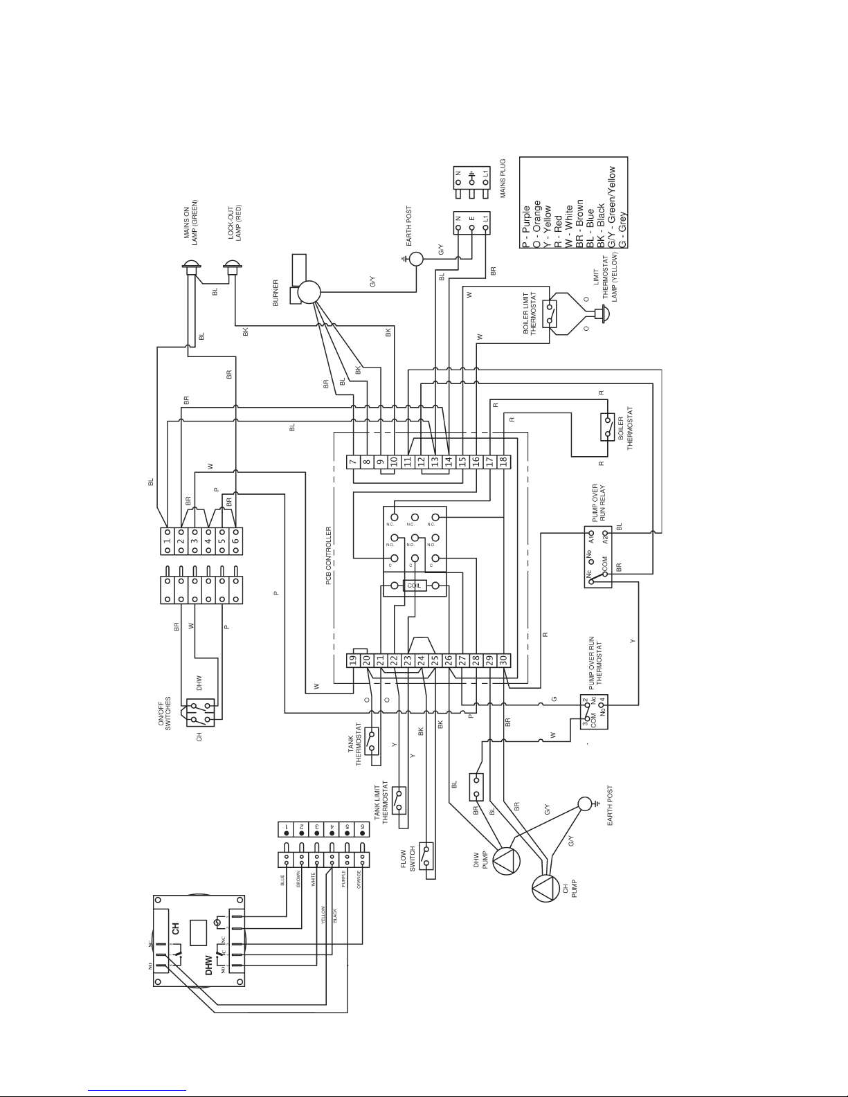
3.3 Combi Wiring Details
3.3.1 Wiring Diagram
The 3 pin mains plug must be supplied with a permanent live to allow the pump overrun stat and relay to operate correctly.
Page 37
Page 35
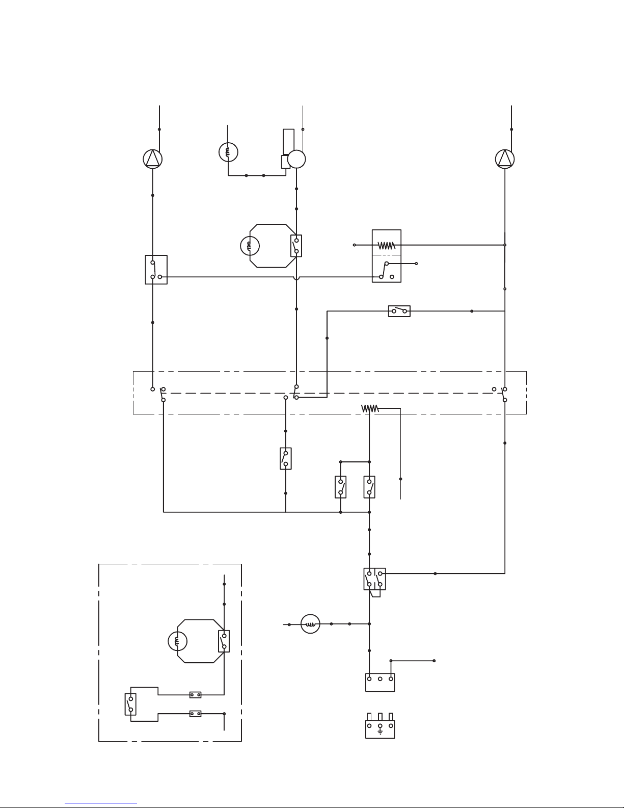
3.3.2 Wiring Schematic
BURNER
D.H.W. PUMP
C.H. PUMP
TRIPLE POLE RE LAY
N.C.
BOILER STA T
N.O.
N.C.
N.O.
N.O.
N.C.
C
C
C
COIL
7
20 21
2425
22
14
N
N
N
N
N
10
8
1
26
29
N
26
28
30
3 19
23
17
18
16
5
L1
N
E
L1
N
MAINS PLUG
H.W.
C.H.
TANK STAT
FLOW SW ITCH
TANK LIMIT
STAT
9
BOILER LIMIT ST AT
15
2
13
1
6
4
MAINS ON
LAMP
(GRE EN)
H/L RESET
LAMP
(YELLOW )
LOCKOUT
LAMP
(GRE EN)
LAMP
7
16
BOILER LIMIT ST AT
15
H/L RESET
LAMP
(YELLO W)
BREAK INTO T HE WHITE
WIRE BETWE EN NO 16 ON
THE PCB AND THE LIMIT
STAT AND CONNECT IN THE
PRESSURE SWIT CHW ITH A
WIRING BLOCK AS SHOW N
LOW PRES SURE
SWIT CH
LOW PRES SURE
SWIT CH
WIRING A L OW PRESSURE SW ITCH
12
WIRING
BLOCK
COIL
N
11
PUMP OVER
RUN STAT
PUMP OVER
RUN RELAY
27
WIRING
BLOCK
NC
NO
C
2
4
3
Page 38
Page 36
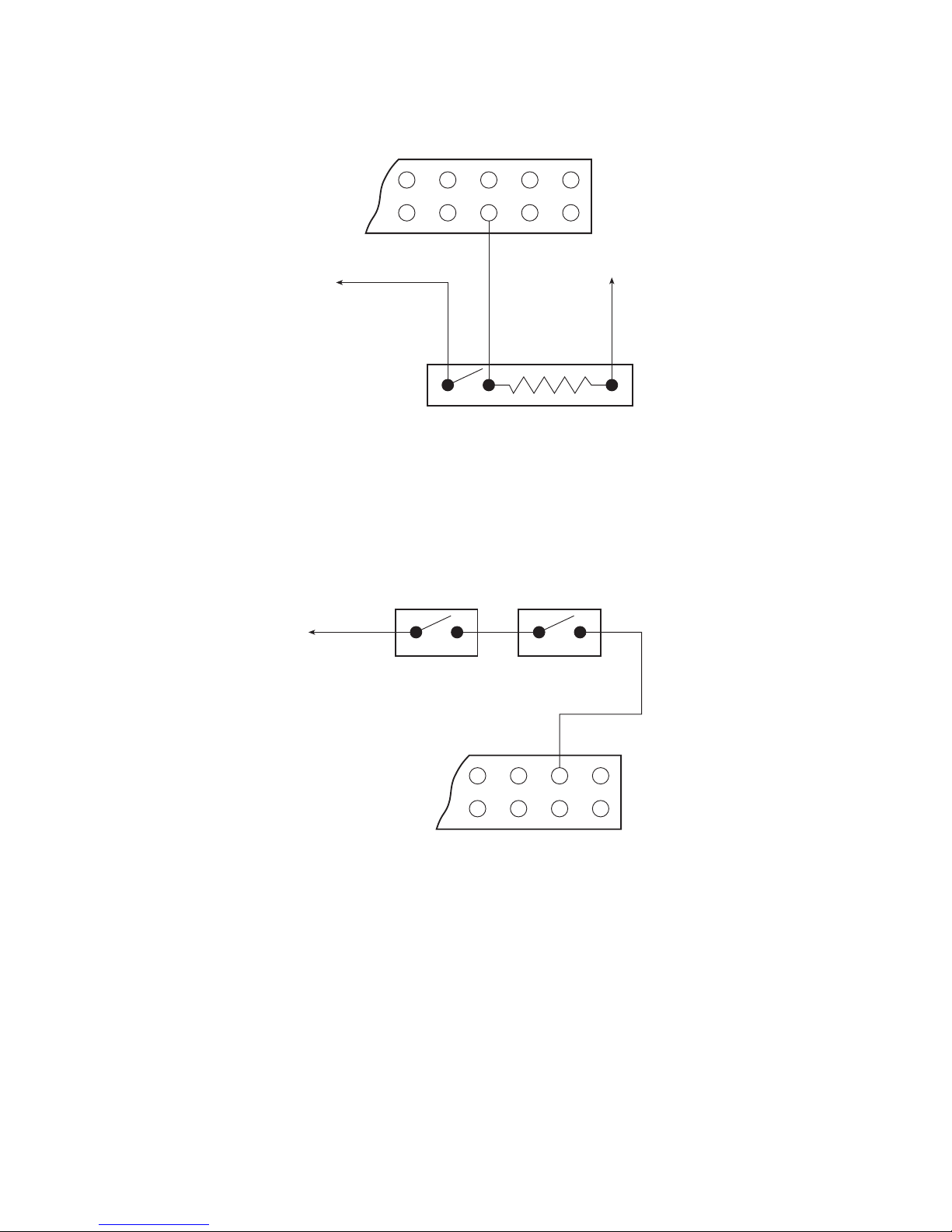
3.3.3 Fitting a Room Thermostat to a Combi
In order to provide frost protection for the fabric of the building a frost thermostat
should be fitted in the coldest room in the house. To prevent over heating of the
property a pipe thermostat should be fitted on the return pipe close to the boiler.
The Kabin Pak Combi boiler is factory fitted with a frost thermostat as standard.
3.3.5 Combi Pump Overrun Thermostat
The Combi boilers have been fitted with a pump overrun thermostat. In order for the
thermostat to work effectively the boiler must be supplied with a permanent live.
Failure to do this will result in nuisance trip outs.
Remove the purple wire from no 5 and no 28 on the PCB and wire the thermostat
as shown. The room thermostat should be located where it is not subjected to
extraneous heat gains, direct sunlight or draughts.
3.3.4 Fitting Frost Protection to a Combi
ROOM THERMOSTAT
282726
PCB
N
5
29 30
FROST THERMOSTAT
PERMANENT
LIVE
543 6
PIPE THERMOSTAT
Page 39
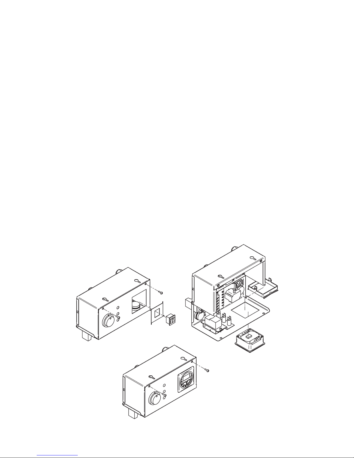
Page 37
3.4 Installation of a Warmflow Combi Optional Programmer (PC1)
1. Disconnect the electrical supply.
2. Drop down control box front (2 screws).
3. Disconnect the 6 pin plug from the CH/HW on/off switched.
4. With a sharp knife cut out the outline of the panel knockout through the facia label
from the front of the panel.
5. With a hacksaw blade or snips remove the knockout piece ensuring that all metal
tags or burrs have been removed from the hole.
6. Feed the programmer and harness through the hole from the front of the panel.
7. Secure in position by attaching the securing bracket to the rear of the programmer.
8. Plug the wiring harness into the 6 way socket.
9. Activate battery back up on the programmer by removing the plastic strip.
10. Close the control panel cover and reconnect the electrical supply.
11. Using the operating instructions located towards the back of this manual or supplied
with the programmer, set the switching times.
Page 40
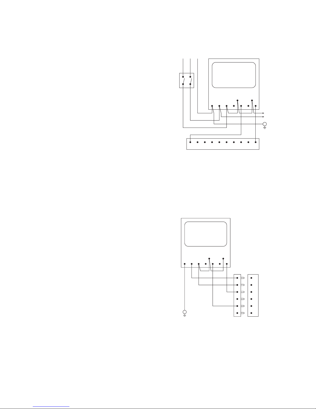
Page 38
3.5 Remote Timers for Combis
3.5.1 Installation of a remote two channel programmer (option 1)
Connecting the programmer in this
manner will bypass the CH and HW on/
off switches on the boiler control panel.
A separate connection to the boiler 3 pin
mains plug is NOT required.
Inside the boiler control panel, remove
the purple and white wires connecting
terminals 5 and 3 on the terminal block
with terminals 19 and 28 on the PCB.
Connect the programmer to the
permanent live mains supply via a fused
isolator as shown.
Connect the boiler to the programmer via a 5 core cable as shown with the
permanent live connecting to terminal 12 on the PCB. Failure to connect the
permanent live to the boiler in this way will prevent the mains lamp and pump
overrun thermostats from operating. It will also prevent the built-in frost protection of
a Kabin Pak Combi from operating.
3.5.2 Installation of a remote two channel programmer (option 2)
When connecting the programmer in this
manner will bypass the CH and HW on/
off switches on the boiler control panel.
The boiler and programmer will both
be powered from the boiler 3 pin mains
plug.
Inside the boiler control panel, remove
the purple, white and brown wires
connecting the CH and HW switches to
the 6 pin connector of the terminal block.
Connect the programmer to the 6 pin
connector via a 5 core cable as shown
ensuring the earth is connected to one of
the earth posts inside the control panel.
Connect the boiler 3 pin mains plug to a permanent live mains supply via a fused
isolator. Failure to connect a permanent live to the boiler will prevent the programmer,
boiler mains lamp and pump overrun thermostats from operating. It will also prevent
the built-in frost protection of a Kabin Pak Combi from operating.
OFFOFFE N L
COM
ON
22 21 20 19
PCB CONTROLLER
ON
COM
CH HW
26 25 24 2328 27
12
11
EARTH
POST
OFFOFFE N L
COM
ON ON
COM
CH HW
1
2
3
4
5
6
EARTH
POST
Page 41
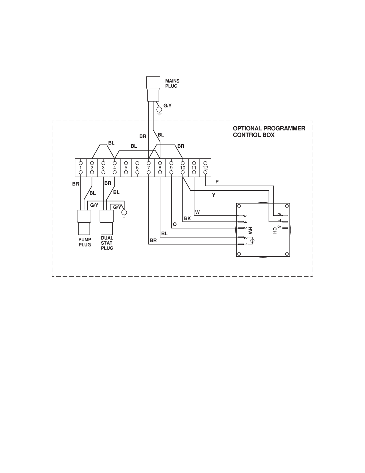
Page 39
3.6 Optional Programmer (PU1) for Non-Combi Models
3.6.1 Programmer Control Box Wiring Diagram
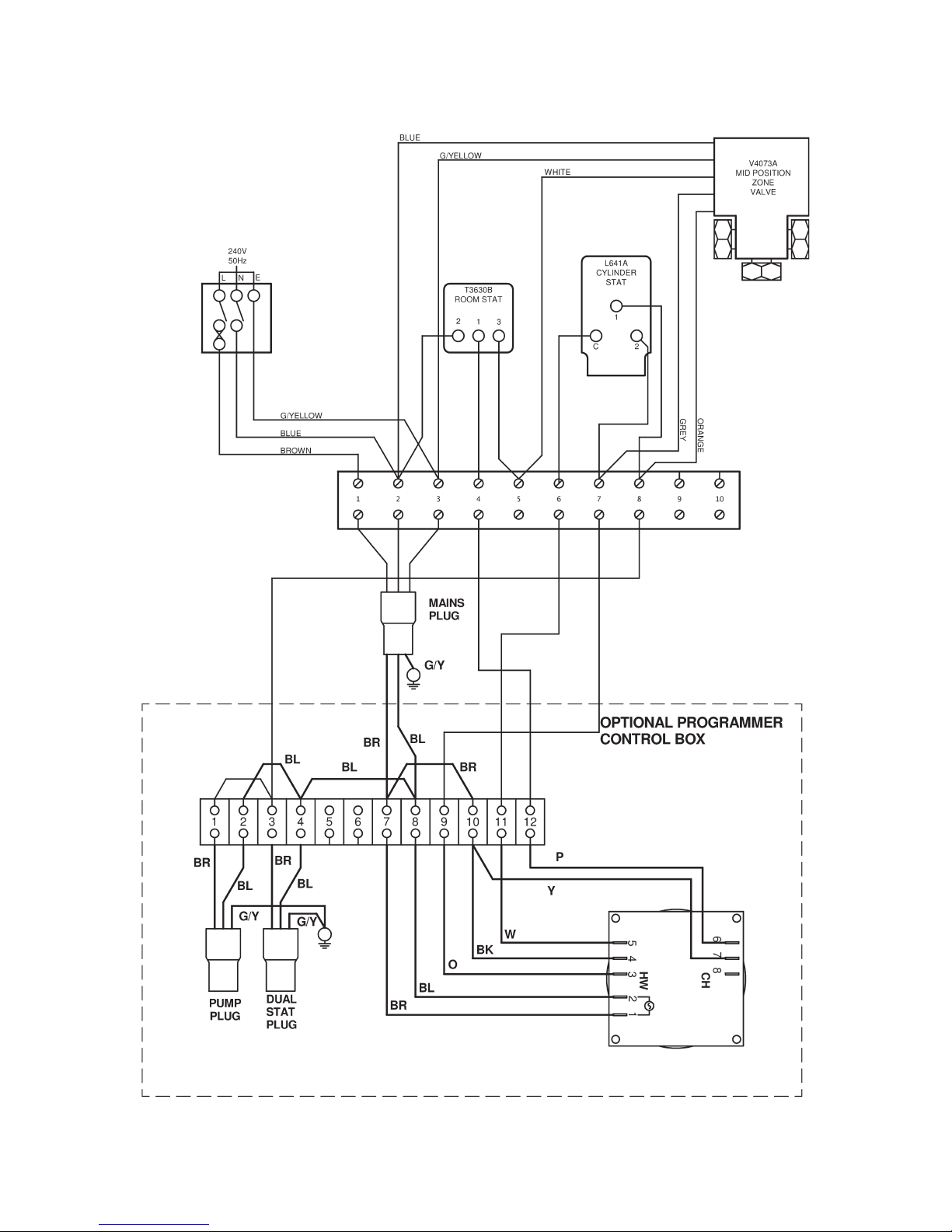
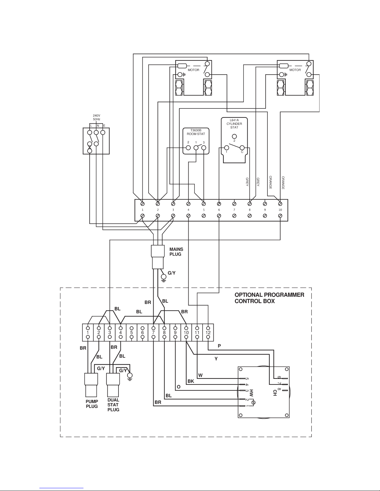
3.6.2 General Requirements
1. The optional programmer as supplied will supply power to the pump and burner via
the central heating channel.
2. When connecting to external controls, eg ‘Y’ plan or ‘S’ plan it will be necessary to
remove the loop between 3 and 12 on the programmer terminal block.
3. The programmer is not suitable for gravity hot water systems.
Page 42
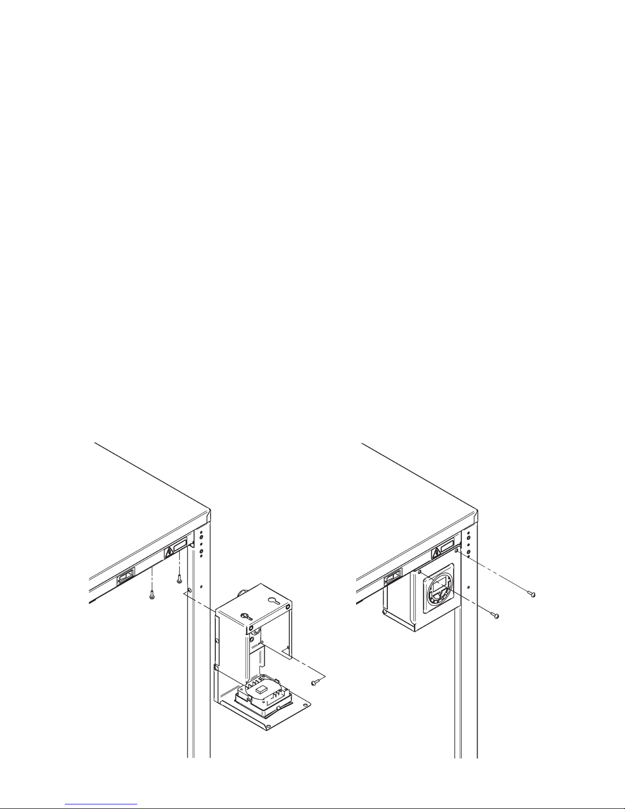
Page 40
3.6.3 Programmer Installation
1. Disconnect electrical supply.
2. Drop down control box front (2 screws).
3. Secure control box to the horizontal casing bracket (2 screws) and right hand side
(1 screw).
4. Connect the thermostat, circulating pump and the mains supply to the leads on the
rear of the control box.
5. Two examples of system wiring are shown in the following sections.
6. If fitting the programmer to a Utility model without an integral pump, disconnect the
pump plug from terminals 1 and 2 of the programmer terminal block and from the
earth post. Remove the pump plug then wire the external pump into terminals 1 and
2 of the programmer terminal block and the earth post, feeding the wire in through
the pump plug cable clamp.
7. Activate battery backup on programmer by removing the plastic strip.
8. Close the control panel cover (2 screws) and reconnect the electrical supply.
9. Using the operating instructions located towards the back of this manual or supplied
with the programmer, set the switching times.
Page 43
Page 41
3.6.4 Honeywell ‘Y’ Plan – Independent CH & DHW (Fully Pumped Only)
Note: Before fitting programmer remove loop between 3 and 12 on the terminal boiler
control panel terminal block.
Page 44
Page 42
3.6.5 Honeywell ‘S’ Plan – Independent CH & DHW (Fully Pumped Only)
Note: Before fitting programmer remove loop between 3 and 12 on the terminal boiler
control panel terminal block.
Page 45
Page 43
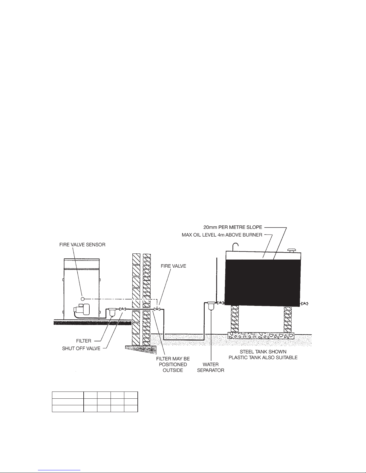
4.0 Oil Supply
1. Oil Tank
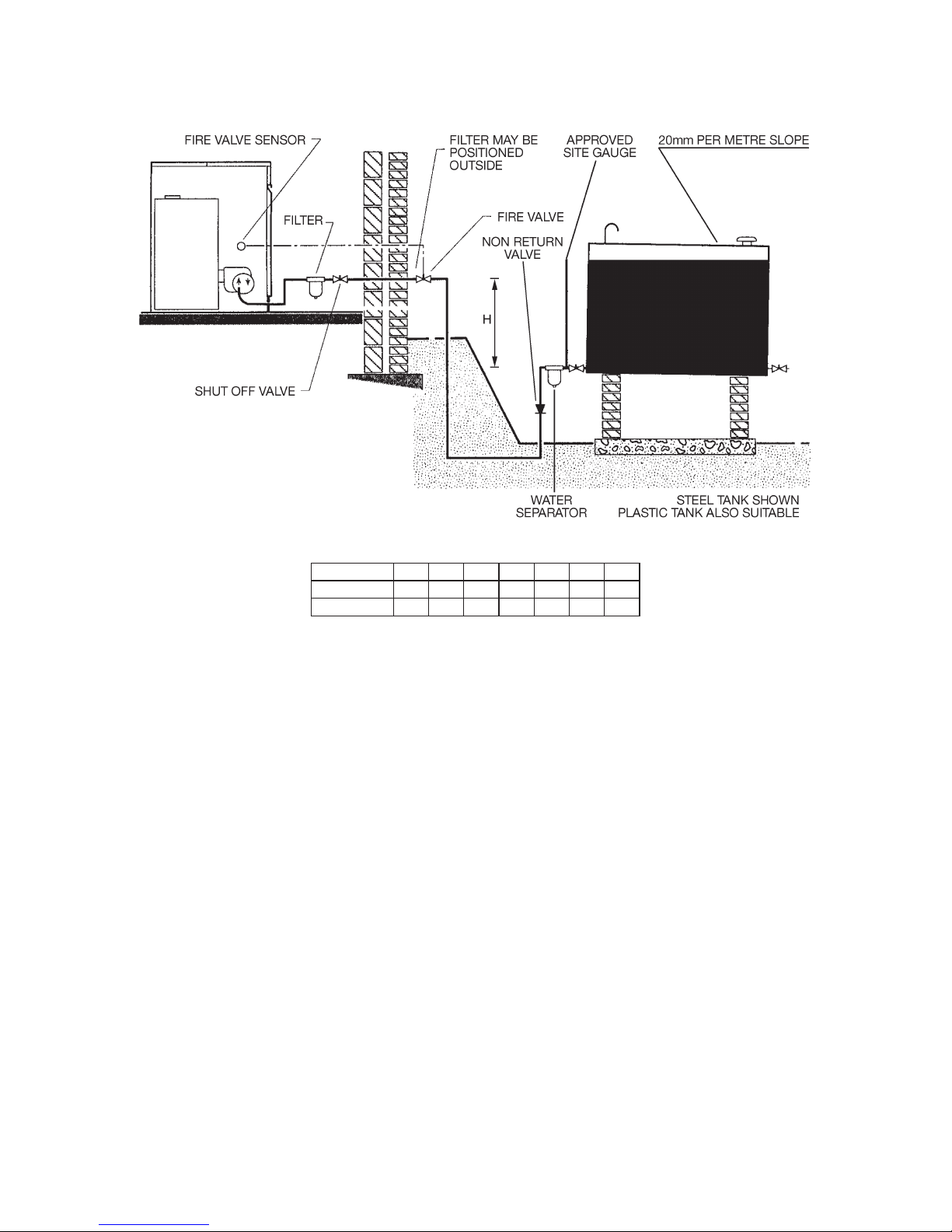
Steel tanks constructed to BS799 : PART 5 should be painted on the outside only
and mounted on piers to prevent corrosion. Plastic oil tanks are also available and
can be suitable for installation at ground level. However, oil should never be stored in
translucent plastic containers.
The tank outlet should be at a height to provide sufficient clearance to allow for
proper maintenance of any isolation valve, oil filter or water separator fitted.
2. The pipe from the oil tank to the burner should be run in copper, steel or aluminium.
Galvanised pipe and fittings should not be used. The pipework should terminate
close to the boiler and be fitted with an isolating valve and filter. A remote sensing
fire valve must be fitted to the oil line preferably before the oil line enters the building
(BS5410 : PART 1).
Depending on the position of the tank a two pipe system may be required. One and
two pipe oil systems are shown below. As an alternative to a two pipe system a
Tigerloop or other approved de-aerator may be used.
4.1 One Pipe Gravity System
Head H(m)
ID 8mm
ID 10mm
0.5 1 1.5 2
10 20 40 60
20 40 80 100
Total Maximum Pipe Length (m)
Note: Plastic oil level gauges may shrink when
exposed to kerosene thus allowing the ingress of
water. Pump failures due to water contamination
are not covered under the warranty.
Page 46
Page 44
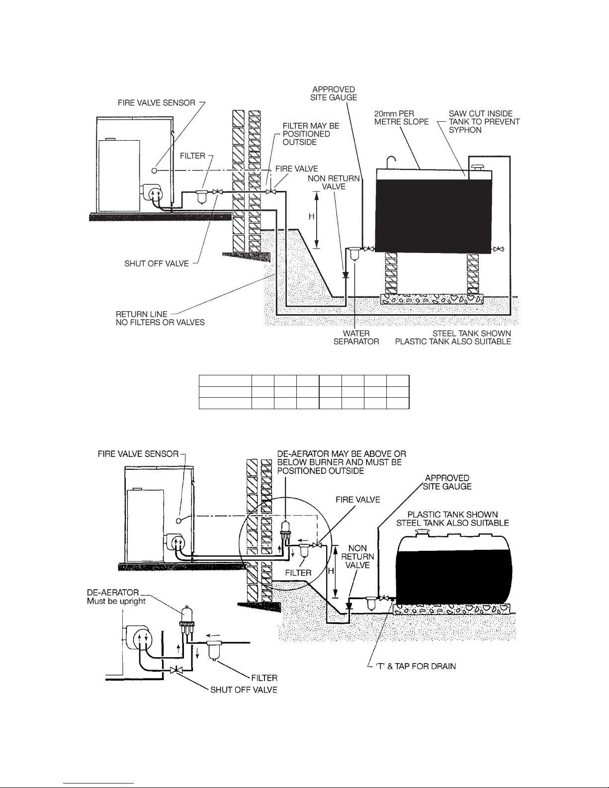
Head H(m)
ID 8mm
ID 10mm
0.5 1 2 3
35 25 15 8
100 100 70 30
0.5
30
100
3.5
6
20
1.5
20
90
Total Maximum Pipe Length (m)
4.2 Two Pipe System
For maximum pipe length and lift contact de-aerator manufacturer.
4.3 De-aerator System
Page 47
Page 45
Head H(m)
ID 8mm
ID 10mm
0.5 1 2 3
35 25 15 8
100 100 70 30
0.5
30
100
3.5
6
20
1.5
20
90
Total Maximum Pipe Length (m)
4.4 One Pipe Lift System
Note: The pump vacuum should
not exceed a maximum of 0.4 bar.
Above this gas is released from the
oil thus leading to burner lock out.
Page 48
Page 46
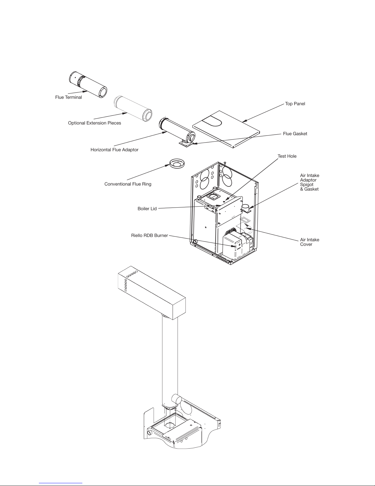
5.0 Flues
5.1 Installation of Flues
Easy Fit High
Level Balanced
Flue (HLBF)
Easy Fit Low
Level Balanced
Flue (BF-R)
Page 49

Page 47
5.1.1 Installation of a Low Level Balanced Flue (BF-R)
1. Make a suitable sized hole in the wall for the flue. For the dimensions of the boiler,
see the Dimensions Section of this manual. For the dimensions of the flue system,
see the Flue Kits & Dimensions Section of this manual.
Note: The cavities around the opening must be sealed and protected by a non-
combustible sleeve.
2. Remove the conventional flue ring, ensuring all the silicone sealant is removed from
the top of the boiler. If installing a 70 or 90 output non-combi model, also remove
the service access door.
3. Carefully fit the inner and outer seals to the flue starter piece and smear them with
soap or an appropriate lubricant (suitable for use with silicone flue seals).
4. If installing a U70, UP70, U90 or UP90 model, remove the lower casing panel
knockout from the appropriate side or rear panel. This is best done with a pair of tin
snips. If installing a U120 or UP120 model, remove the upper knockout.
Push the boiler into position against the wall, correctly locate the gasket on the boiler
then install the flue starter piece, securing it in position using the fasteners provided.
5. If installing extension pieces, ensure the seals are correctly fitted and lubricated
before pushing through the wall and into the starter piece.
Note: Any combination of short (300mm) or long (600mm) extension pieces for the
BF-R can be used up to a maximum total length of 1200mm.
6. Slide the flue terminal into position with a twisting movement ensuring that it
protrudes through the wall by a minimum of 175mm and a maximum of 225mm.
7. Seal the gap between the flue and the wall both inside and outside, then fit the
terminal guard (basket) over the flue terminal. Use the cardboard mounting template
supplied with the flue kit to locate and drill the necessary screw holes in the wall.
8. Remove the air inlet cover from the burner then fit the intake adaptor spigot and
gasket. Connect one end of the air duct / hose to the flue and the other end to the
adaptor spigot and secure.
5.1.2 Installation of a High Level Balanced Flue (HLBF)
The ‘Easy Fit’ High Level Balanced Flue (HLBF) can only be used with the 120
Output Models (B120, U120 & UP120) when fired at the factory setting (0.85 gal
nozzle). It CANNOT be used when fired with a 1.00 gal nozzle.
Install as per the above instructions noting that there are no flue seals to fit, the flue
is not telescopic and there are no extension pieces available for this flue type.
Page 50
Page 48
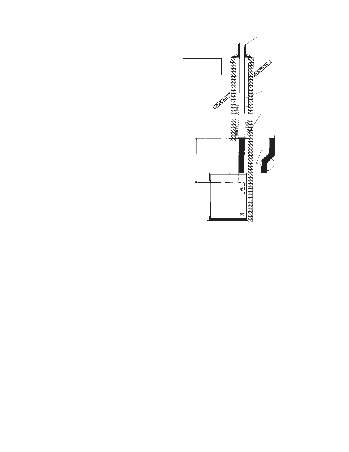
5.2 Conventional Flues
The flue system should be designed
in accordance with local bye-laws
and the Building Regulations. Draught
stabilisers are not recommended for oil
fired boilers. Sharp bends or horizontal
runs should be avoided and the flue
should terminate 2 feet (600mm) above
the ridge of the dwelling. Terminals
which restrict the discharge or allow
ingress of water should be avoided.
When connecting to an existing
masonry chimney a flexible stainless
steel liner of the correct diameter must
be used. The annular space must be
filled with insulation and sealed top
and bottom. The starter piece should
be sealed into the conventional flue
adaptor using a high temperature
silicone sealant or fire cement.
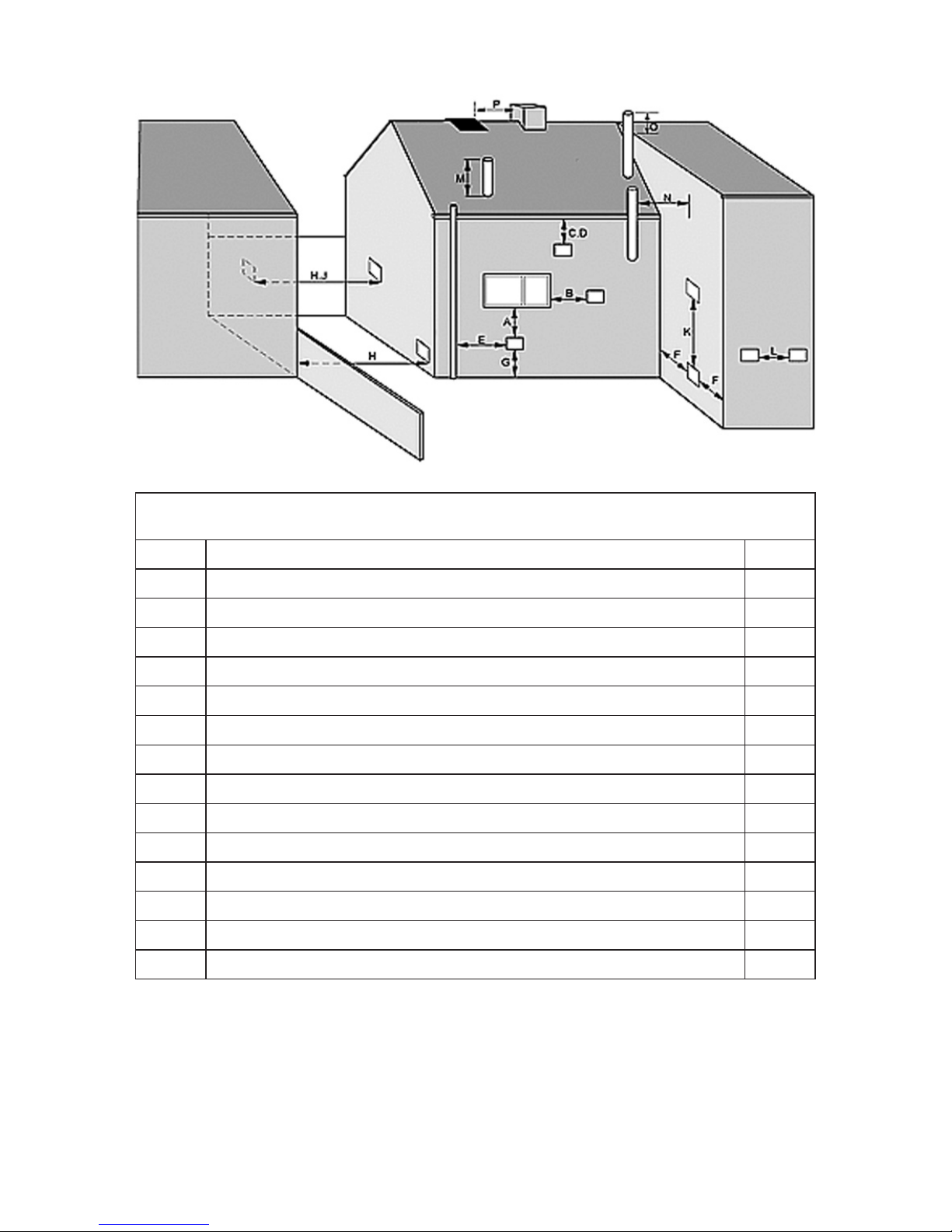
5.3 Low Level Balanced Flue Terminal Positions
Attention should be given to the position of the flue discharge; we recommend the
following guidelines be adopted.
1. The flue should not discharge beneath opening windows or near other accesses to
the building.
2. The flue should not discharge near internal/external corners of the building where
turbulent wind conditions could occur.
3. A terminal guard must be fitted at all times.
4. The terminal should not discharge over property boundaries.
5. Discharge into narrow passageways should be avoided.
6. The location of the terminal and routing of the flue should be determined by the
installer after consultation with the householder.
7. In positioning the flue the wind direction should be considered.
Installation in exposed positions is not recommended.
Cowls and pots that
may restrict the flue
should not be used
TERRACOTA POT
Considered good practice
but is not a guarantee of
overcoming down drafts
LINER
Suitable liner same
diameter as Boiler
Flue connection
Starter piece
stainless steel same
diameter as flue
SORT
DOOR
FLUE PIPE BENDS
DO NOT USE 90°
Typical Conventional Flue with Brick Chimney
TEST POINT
135°
2 metres max
Page 51
Page 49
These are minimum dimensions and are only quoted as a guidelines.
Terminating positions must be at least 1.8 metres from an oil storage tank unless
a wall with at least 30 min fire resistance and extending 300mm higher and
wider than the tank is provided between the tank and the terminating position.
From an internal or external corner or surface or boundary alongside the terminal.F 300
Above ground or balcony level.G 300
From a surface or a boundary facing the terminal.H 600
From a terminal facing the terminal.J 1,200
Vertically from a terminal on the same wall.K 1,500
Horizontally from a terminal on the same wall.L 750
Above the highest point of an intersection with the roof.M 600
From a vertical structure on the side of the terminal.N 750
Above a vertical structure less than 750mm from the side of the terminal.O 600
From a ridge terminal to a vertical structure on the roof.P 1,500
A 600Directly below an opening, air brick, opening window etc.
B 600Horizontally to an opening, air brick, opening window etc.
C 75
Below a gutter or a balcony without protection.D 600
From vertical sanitary pipework.E 300
Below a gutter, eaves or balcony with protection.
MINIMUM DISTANCES TO TERMINALS IN MILLIMETRES AS MEASURED FROM
THE TOP OF THE CHIMNEY OR THE RIM OF A LOW LEVEL DISCHARGE OPENING
Page 52
Page 50
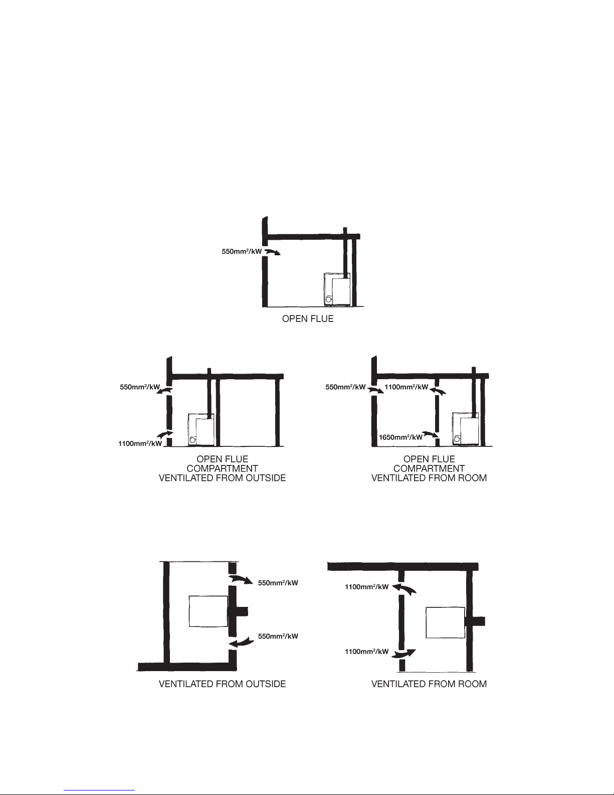
6.0 Air Supply for Combustion & Ventilation
(see BS5410)
6.1 Open Flue Boilers
When the boiler is sited in a cellar where the only access for combustion and
ventilation air is at high level then the combustion air should be ducted to low level.
Combustion Air Supply
Boiler in Room
Boiler in Compartment
6.2 Balanced Flue Boilers – Boilers in a Compartment
Air Supply for Ventilation
No Combustion Air Inlet required to Room
Page 53

Page 51
7.0 Installation Requirements
The boiler installation must be in compliance with BS5410 : PART 1 and the Building
Regulations.
7.1 General Requirements
7.1.1 Hearth
The boiler hearth temperature is between 50°C and 85°C and should be stood on
a rigid, non-porous, non-combustible base, which is not softened by warmth, to
comply with the Building Regulations.
7.1.2 Service Access
24” (600mm) Clearance should be provided above and in front of the boiler to allow
for routine servicing. Additionally, Pumped, System and Combi models may require
access to the top.
7.1.3 Heating System
The heating system should be installed to HVCA current codes of practice. Before
installing the boiler the new or existing system must be thoroughly flushed to clear
all sludge or other foreign matter such as solder, steel wool and copper filings. The
system must be cleansed, neutralised and protected from corrosion in accordance
with BS5449 and BS7593 using suitable cleansing agent(s) and inhibitor(s) and
carried out in accordance with the cleanser / inhibitor manufacturers’ instructions.
The system must be dosed to the concentrations specified by the inhibitor
manufacturer (refer to the Technical Data section of this manual for the volume of the
boiler when calculating the total system volume). Failure of components such as, but
not limited to, pumps, auto air vents, pressure relief valves, plate heat exchangers
and non-return valves due to corrosion product in the system will not be covered by
warranty.
7.1.4 Air Vents
The plastic plugs of the auto air vent(s) factory-fitted to the boiler must be loosened
when filling the system in order to bleed the air from the boiler. In addition to any
factory fitted air vents it is recommended that another air vent is fitted at the highest
point in the system. Where the flow pipework drops down from the boiler the installer
must ensure that an automatic air vent is fitted to the top of the pipework to prevent
air being trapped in the boiler.
7.1.5 Drain Cock
For all appliances not factory-fitted with drain cocks, one should be fitted to the
boiler drain boss located to the left hand side of the burner. Drain cocks should also
be fitted to the lowest points in the system to allow the system to be completely
drained.
7.1.6 Frost Protection
Where there is a risk to the boiler or installation from frost then a suitable frost
thermostat should be fitted. Alternatively the system could be dosed with an anti
freeze agent. The Kabin Pak Combi boiler is factory fitted with a frost thermostat as
standard. For all other Kabin Pak models covered by this manual a Frost Thermostat
Kit (Code FSK1) is available as an optional extra.
7.1.7 Pipework
We strongly advise that all installation pipework is run in copper. However, if plastic
pipe is used, it must be recommended by the pipe manufacturer for use with oil fired
appliances and, in any case, the last 1000mm of pipework connected directly to the
appliance must be of copper. All connections to the appliance must be made with
compression fittings.
Page 54

Page 52
7.2 Sealed Systems
7.2.1 Expansion Vessel
Refer to BS7074: PART 1 and BS5449 for details of expansion vessel sizing. The
values given in the table below are for total system volumes which include the
primary water capacity of the boiler which can be found in the Technical Data section
of this manual. System and Combi models up to 120 are supplied with a 12 litre
expansion vessel charged to 1.0 bar. This can accommodate a maximum combined
boiler and system volume of 110 litres. Where permitted by the type, size and
configuration of heating system the expansion vessel bladder pre-charge pressure
can be reduced, prior to filling the system, to 0.5 bar in order to accommodate
a total system volume of 145 litres. If these maximum total system volumes are
exceed, additional expansion capacity will be required.
When measuring the expansion vessel bladder pre-charge pressure, using a tyre
gauge, the system should be cold and the system pressure should be relieved (by
manually operating the system pressure relief valve) in order to obtain an accurate
reading.
7.2.2 System Filling
For all System and Combi boilers a filling point complete with a filling loop is supplied
fitted to the expansion vessel. The filling loop must be disconnected from the mains
supply after filling. A system pressure when cold of 1 bar is recommended. After
filling, vent all air from the system. The plastic plugs of the auto air vent(s) factoryfitted to the boiler must be loosened when filling the system in order to bleed the air
from the boiler.
7.2.3 System Pressure
Water loss from the system as indicated by a reduction in pressure on the pressure
gauge may be made up through the filling loop. In the first week of operation it is
normal to see a drop in system pressure. After this time the system pressure must
be rechecked and the system refilled. Failure to do so may lead to boiler faults.
7.2.4 Pressure Relief Valve
Any pressure relief valve fitted to the boiler or system must be able to discharge
externally to a drain where the discharge can be seen but cannot cause any injury
or damage. No other valves should be positioned between the relief valve and
discharge termination.
7.2.5 Low Pressure Switch
Where there is a catastrophic loss of water from the system the boiler thermostats
may fail to operate which would result in serious damage to the appliance. To
prevent this it is recommended that a low pressure cut out switch set at 0.2 bar is
fitted to the system and wired in series with the boiler limit thermostat.
25.0
32.7
46.8
300
VESSEL VOLUMES
22.9
30.0
42.9
275
20.8
27.2
39.0
250
18.7
24.5
35.1
225
16.7
21.8
31.2
200
14.6
19.1
27.3
175
12.5
16.3
23.4
150
10.5
13.6
19.5
125
8.3
10.9
15.6
100
6.3
8.2
11.7
75
4.2
5.4
7.8
50
2.1
2.7
2.9
25
0.5
1.0
1.5
TOTAL SYSTEM
VOLUME
INITIAL CHARGE
Page 55
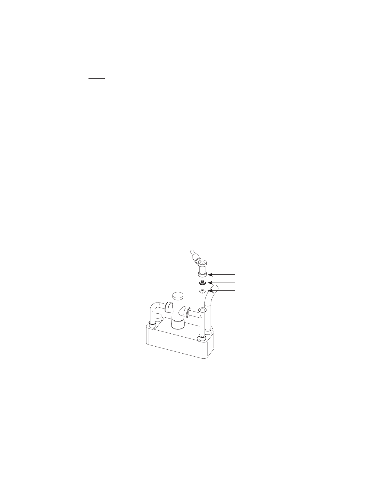
Page 53
7.3 Combi Domestic Hot Water
7.3.1 Mains Water Pressure
To protect the appliance and to prevent excessive flow rates, a pressure reducing
valve must be fitted to limit the maximum supply pressure to 3 bar. We strongly
advise that all installation pipework is run in copper. However, if plastic pipe is used,
it must be recommended by the pipe manufacturer for use with oil fired appliances
and, in any case, the last 1000mm of pipework connected directly to the appliance
must be of copper. Whenever a pressure reducing valve or other device containing
a non-return valve is fitted to the mains water supply entering the boiler, a mini
expansion vessel must be fitted AFTER the device in order to protect the appliance
from the expansion due to heating of the water in the domestic hot water pipework.
Note that the flow rate from individual taps is dependant on the number of outlets
being operated together, as well as the length and size of pipework and the mains
supply pressure.
7.3.2 Water Hardness
Although many of the DHW components are designed to resist lime scale formation,
in areas of hard water it may still be necessary to fit an inline chemical water softener.
For further information contact Warmflow and your local water company.
7.3.3 Hot Water Pipework
To ensure economic use, the pipe runs between the boiler and the taps should be
as short as possible and insulated to reduce heat loss. Very long pipe runs can lead
to excessive water usage and poor efficiency.
7.3.4 Flow Restrictor
An 18L/min flow restrictor has
been factory fitted but can be
easily removed if required.
7.3.5 Boreholes
Where the mains water supply to the boiler is fed from a borehole via a pump and
accumulator arrangement the variable pressure can cause the mixer valve to go to
its fail safe settings thus preventing the outlet water temperature from achieving a
suitable level. In order to minimise the pressure variations it is recommended that
differential on the borehole pump pressure switch is kept as low as possible without
adversely affecting the pump motor. The accumulator must be as large as possible
in order to reduce the rate of pressure change and a pressure reducing valve (PRV)
must be situated between the pump and accumulator and the boiler. The PRV must
be set slightly below the minimum setting of the pressure switch on the pump.
FLOW SWITCH
FLOW RESTRICTOR
WASHER
Page 56
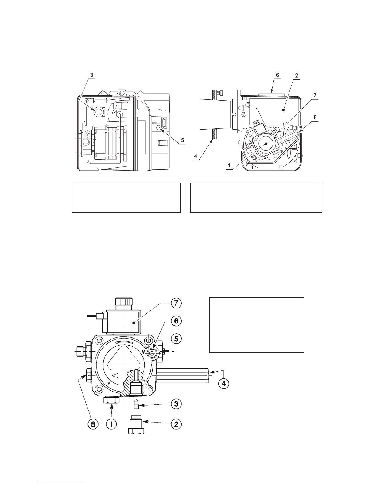
Page 54
8.0 Burners
8.1 RDB Burner
8.2 Oil Pump
The burner is supplied for use with a one pipe system. For use on a two pipe
system, it is necessary to remove the return port plug and fit a small by-pass plug as
shown.
1. Pump
2. Control Box
3. Reset Button with Lock-Out Lamp
4. Flange with Insulating Gasket
5. Air Damper Adjustment Screw
6. Air Tube Connection (Supplied with BF Kit)
7. Pump Pressure Adjustment Screw
8. Pressure Gauge Port
1. Suction Line
2. Return Line
3. By-Pass Screw
4. Gauge Connection
5. Pressure Adjuster
6. Suction Gauge Connection
7. Valve
8. Auxiliary Pressure Test Point
Page 57
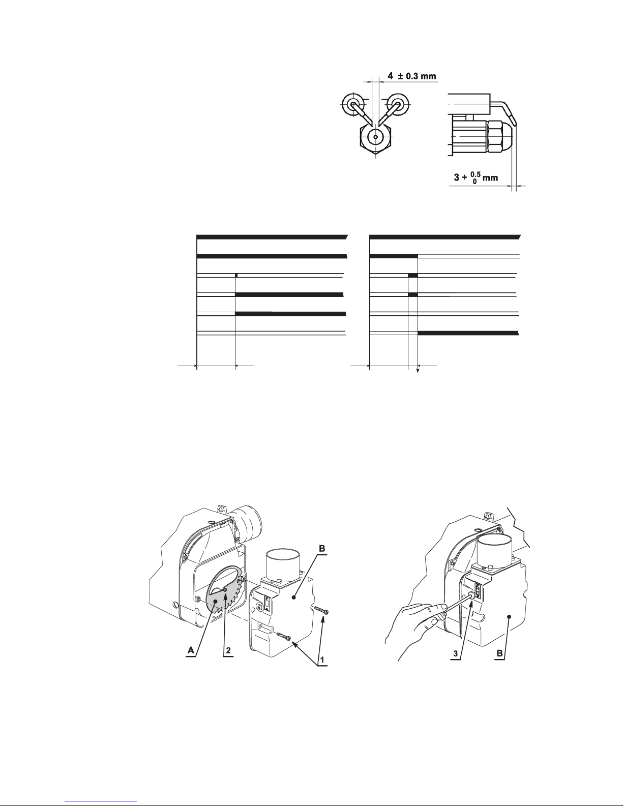
Page 55
8.3 Electrode Setting
8.4 Burner Start-Up Cycle
8.5 Air Damper Adjustment
The air damper is set in factory. This regulation is purely indicative. Each installation
however, has its own working conditions: actual nozzle output; positive or negative
pressure in the combustion chamber, the need of excess air, etc. All these conditions
may require a different air damper setting.
Air Damper (A) – The main air damper can be set in
either of two positions. To set the positions of the damper,
proceed as follows: Remove the secondary air damper (B)
loosening the screws (1). Loosen the screw (2) and rotate
the main air damper (A) to the required position. Retighten
the screw (2) and put back the secondary air damper (B).
Air Damper (B)
– The purpose of
this damper is to perform a finetuning of the inlet air. Tuning of this
device is possible by turning the
screw (3).
Air Damper (A) – 15/21 Burner Only Air Damper (B)
~ 12s
Thermostat
Motor
Ignition Transformer
Valve
Flame
Lock-Out Lamp
~ 12s
Normal Lock-out due to failure to light
~ 5s
When removing or replacing the nozzle,
move the electrodes forward to avoid the risk
of damage. The electrodes are slackened
by unscrewing the brass post that passes
from the electrode holder out of the side
of the burner. When work is complete,
ensure the electrodes are reset as shown
and secured by tightening the brass post.
Page 58
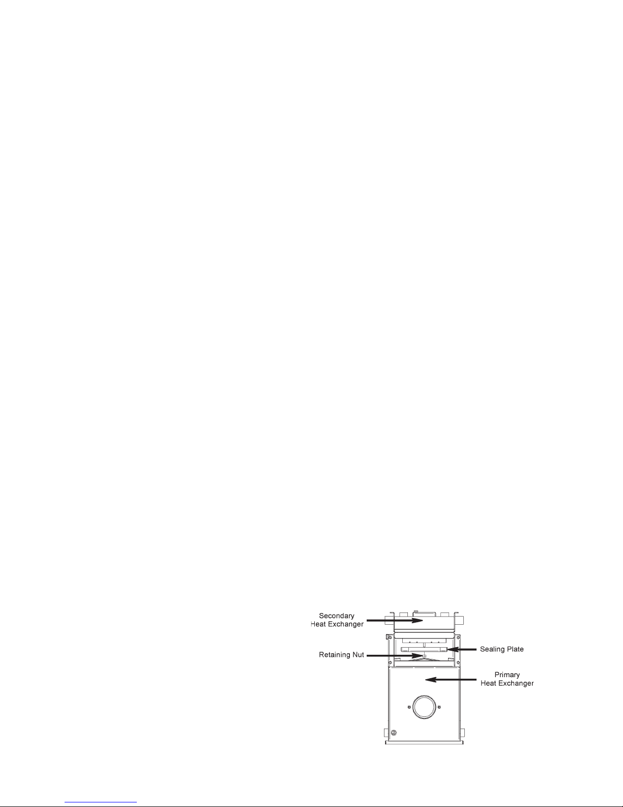
Page 56
9.0 Commissioning & Servicing
9.1 Commissioning
It is the responsibility of the installer to ensure that the boiler is properly
commissioned by an OFTEC trained and registered technician. Failure to do
so WILL invalidate ALL warranties.
Before firing ensure that all the baffles are in place, as they may have been displaced
during transit; Refer to the General Information section. Switch the boiler on,
ensuring all controls are calling for heat.
The oil pump pressure must be checked by fitting a pressure gauge to the pump
pressure port. If necessary the pressure should be adjusted until it corresponds with
the value in the Technical Data section for the required output. Using a smoke pump,
check the smoke number. It should be zero.
Using a flue gas analyser, check the CO2 content and flue gas temperature once the
boiler is hot. Testing while the boiler is still relatively cold gives inaccurate results and
leads to incorrect adjustments being made. Where a balanced flue has been fitted
ensure the air duct connecting the flue and burner has been properly connected
before commissioning.
To comply with the building regulations OFTEC form CD11 should be completed
and a copy left with the householder.
9.2 Servicing
9.2.1 General Requirements
It is recommended that the appliance is serviced annually by a Warmflow or an
OFTEC registered service technician in accordance with the recommendations
laid out in OFTEC’s technical information book 2 – ‘Pressure Jet Appliances
– Commissioning Requirements for Technicians’.
Additionally, when servicing, special attention should be paid to the condition of
the oil nozzle, flexible oil line, fuel filter, door insulation, sealing rope. If found to be
defective they must be replaced.
The system corrosion inhibitor level must be checked (instant on-site test kits are
available from inhibitor manufacturers) and additional inhibitor must be added if the
system is found to be under-dosed. Refer to the inhibitor manufacturer for further
guidance.
Note: All product warranties will be invalidated if the appliance is not serviced
annually by a Warmflow or OFTEC trained and registered technician.
9.2.2 Specific Requirements
To access the secondary heat
exchanger of the 120 output
models for servicing, remove the
sealing plate (see diagram) by
unscrewing the retaining nut. Lower
the sealing plate and remove. The
inner underside of the secondary
heat exchanger should be scrubbed
clean using a wire brush or similar.
Page 59
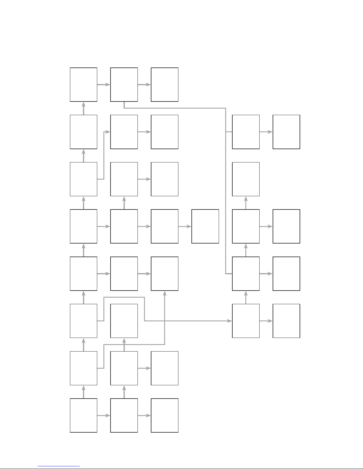
Page 57
10.0 Burner Fault Finding
10.1 Riello RDB
OK
YES YES YES
NO NO NO
YES
NO
NO
NONO
NONONONONO
YESYES YES
Burner
Motor Runs
Lock Out
within
1 second
Lock Out after
12 second
purge
Ignition
Spark Proved
Pump
Produces
Pressure
Nozzle
Atomising Fuel
Combustion
Air Set
Correct
Combustion
Head Set
Correct
Check
L & N to
Control Box
Motor or
Pump Seized
Repair/Replace
Motor/Pump
Check and Set
the Electrodes
Washing
Pressure
1-2 Bar
Solenoid
Operating
Raise Pressure
Replace
Nozzle
Flame Off
and Re-Lights
Check
Boiler Controls
Replace Motor
Capacitor
Replace the
Control Box
Drive Coupling
Broken
Replace the
Coil and/or
Stem Valve
Contaminated
Fuel Filter
Boiler or Flue
Blocked
Repair or
Replace Oil
Pump
Motor gives
50 Volts to
White Wire
Coil of
Solenoid
Functional
Photo Cell
Functional
Replace
Control Box
If B/F
application
remove burner
snorkel tube
and retest
Replace
Burner Motor
Replace
Solenoid Coil
Replace
Photo Cell
Reset B/F Flue
or Reposition
YES NO YES YES YES YES YES
NO NO NO
Page 60
Page 58
11.0 Combi Fault Finding
11.1 Central Heating
YES
YES
YES
NO
YES
YES
NO
YES
NO
NO
NO
Switch on power,
set selectors
for CH on and
DHW off.
Set all controls
to call for heat.
Does the
burner fire?
Is lockout lamp
on burner or
panel lit?
Is high limit
thermostat
lamp lit?
Is there continuity
across the boiler
stat connections
17 and 18 on the
PCB?
Is there continuity
across the
connections
28 and 30 on
the PCB?
Check power
from clock or
switch, check
wiring fuses and
mains supply.
Refer to burner
fault finding.
Press reset
button, replace
if necessary.
Check wiring,
replace boiler
thermostat.
Check relay and
PCB, replace if
necessary.
Do radiators
get hot?
Does boiler
cycle on its
thermostat?
Check all valves
are open and
pump is working,
check pressure,
check all air is
vented.
Check boiler
thermostat,
replace if
necessary.
HEATING IS
WORKING
NORMALLY
NO
NO
YES
Page 61
Page 59
11.2 Domestic Hot Water
Switch on power,
set selectors to CH
off and DHW on.
Is DHW pump
working?
Is there continuity
across connection 20
and 21 on the PCB?
Check wiring, replace
tank thermostat.
Is there continuity
across 25 and 27?
Check wiring, replace
relay, replace PCB.
Check wiring,
replace pump.
Does burner fire? Do radiators get hot?
Check plumbing,
replace non-return
valve.
Refer to burner
fault finding.
Is lockout lamp on
burner or pump lit?
Does tank get hot?
Vent all air from system
pumps, ensure all
valves are open.
Press reset button,
replace limit
thermostat.
Is high limit
thermostat lamp lit.
Does boiler shut down
when tank reaches
temperature?
Replace tank stat,
replace relay.
Check wiring, replace
tank limit stat.
Is there continuinity
across 23 and 22?
With tap closed, switch
the CH switch to on.
Check wiring, replace
relay, replace PCB.
Is there continuinity
across 22 and 16?
Do radiators get hot? Check CH fault finding.
Check power from
clock or switch, check
wiring, check fuses.
Does CH pump stop
when tap is opened?
Check flow switch,
check relay.
Is hot water produced
when tap is opened.
BOILER IS WORKING
NORMALLY
NO NO
NO
YES
NO
NO
NO
YES
YES
YES
NO
NO
NO
NO
YES
YES
NO
YES
YES
YES
YES
YES
Check mixer valve,
check plate heat
exchanger for blockage,
ensure all air is vented
from boiler.
YES
YES
NO
NO
NO
YES
Page 62
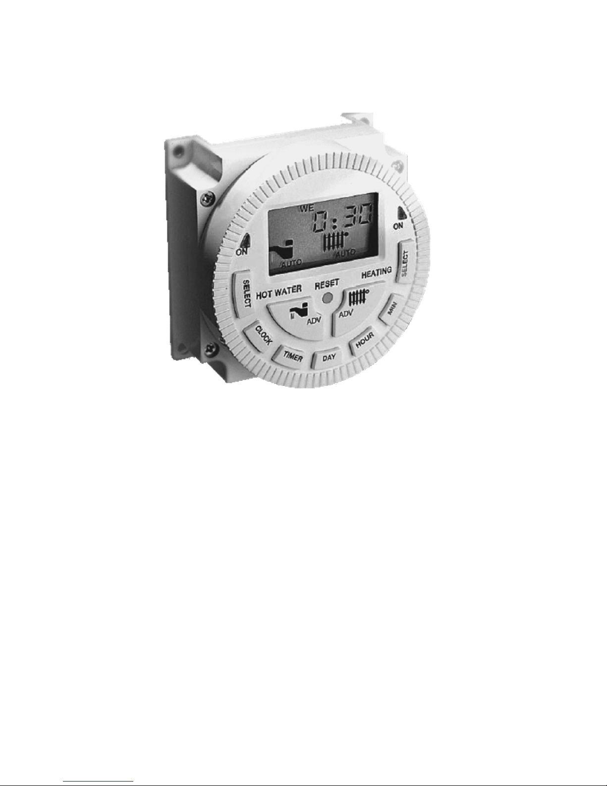
Page 60
12.0 Optional Boiler Mounted Digital Timer
12.1 Operating Instructions
12.1.1 After Installation
When you first install the Cr2032 battery (by removing the clear plastic strip from the
rear of the timer) you must press the ‘RESET’ button, the LCD display will display
fully for 3 seconds. Then LCD display will change to ‘5:2d’. You can press DAY
button to select ‘7d’, ‘24H’ programme mode.
This configures the timer as follows:
5/2d: 5 day/2 day programme option allows different ON/OFF times on
weekday and weekend.
7d: 7 day programme option allows different programme setting on each
day of weekday and weekend.
24H: 24 hours programme option runs same programme every day.
When you finalise the setting, press the CLOCK button for normal operation.
Page 63

Page 61
12.1.2 Built in Programme
For convenience, the timer module has a built in programme, however, it can be
easily adjusted (see section 12.5 To Change the Programmes).
The timer offers 3 options for both CH and HW programme period.
OFF: Off all the time.
AUTO: To run your time schedule for period one or two or three each day.
ON: Turn on all the time.
Factory Present Time Schedule
12.1.3 To Set Current Time & Day
1. Press and hold
CLOCK button then press DAY button to select current day
of the week.
2. Press and hold
CLOCK button then press HOUR button until the correct
hour is displayed.
3. Press and hold
CLOCK button then press MINUTE button until the correct
minute is displayed.
12.1.4 Select Operation Mode
Press CH SELECT / HW SELECT button to select operation mode to be
OFF,
AUTO, ON.
22:3022:30
16:30
14:00
12:00
10:30
07:30
22:3022:30
16:30
14:00
12:00
08:30
06:30
HW/CH2CH/CH1
16:30
14:00
12:00
08:30
06:30
16:30
14:00
12:00
10:30
07:30
HW/CH2CH/CH1
Mon – Fri
Time Schedule
Mon – Fri
Time Schedule
PERIOD 1 ON
PERIOD 1 OFF
PERIOD 2 ON
PERIOD 2 OFF
PERIOD 3 ON
PERIOD 3 OFF
Switching
Page 64

Page 62
Set Day Programme Period 1 On/Off
22:30
07:30
22:30
06:30
HW/CH2CH/CH1
22:30
06:30
22:30
07:30
HW/CH2CH/CH1
Mon – Fri
Time Schedule
Mon – Fri
Time Schedule
PERIOD 1 ON
PERIOD 1 OFF
Switching
Set Day Programme Period 3 On/Off
22:3022:30
16:30
14:00
12:00
10:30
07:30
22:3022:30
16:30
14:00
12:00
08:30
06:30
HW/CH2CH/CH1
16:30
14:00
12:00
08:30
06:30
16:30
14:00
12:00
10:30
07:30
HW/CH2CH/CH1
Mon – Fri
Time Schedule
Mon – Fri
Time Schedule
PERIOD 1 ON
PERIOD 1 OFF
PERIOD 2 ON
PERIOD 2 OFF
PERIOD 3 ON
PERIOD 3 OFF
Switching
Set Day Programme Period 2 On/Off
10:30
07:30
22:30
16:30
08:30
06:30
HW/CH2CH/CH1
22:30
16:30
08:30
06:30
10:30
07:30
HW/CH2CH/CH1
Mon – Fri
Time Schedule
Mon – Fri
Time Schedule
PERIOD 1 ON
PERIOD 1 OFF
PERIOD 2 ON
PERIOD 2 OFF
Switching
22:30
16:30
22:30
16:30
12.1.5 To Set Programme Period
Press and hold
DAY button and press MIN until the correct programme period is
displayed.
12.1.6 Reviewing the Programmes
Press
TIMER button each time to toggle through the ON and OFF settings.
12.1.7 To Change the Programme
1. Press
TIMER key repeatedly until the particular ON or OFF time appears.
2. Press
HOUR button and MINUTE button to set new ON or OFF time.
Page 65

Page 63
12.1.8 Manual Select
1. Press
SELECT to toggle through ON / AUTO / OFF modes as indicated by
the timer status.
2.
ON mode turns on the timer.
3.
OFF mode turns off the timer.
4.
AUTO mode runs the set programme.
12.1.9 Manual Select
This function is only applicable when your timer is set on
AUTO mode.
You can temporarily override the normal switching times by pressing the ADV key.
The temporarily override won’t affect the normal programme after execution of the
override.
1. Press CH ADV
or HW ADV key the CH icon or HW icon will flash.
2. In approximately 5 seconds the display CH select mode ‘AUTO’ or HW select
mode ‘AUTO’ will flash and go into the manual override function.
3. OFF mode turns off the timer.
4. To cancel override by pressing CH ADV
or HW ADV and the ‘AUTO’ will stop
flash.
12.1.10 Manual Hour
1. Press CH ADV
or HW ADV key, the CH icon will flash.
2. You now have approx 5 second to enter desired length of time by pressing
CH ADV
or HW ADV key once for each hour the new time set should be in
affect.
3. The MANUAL HOUR function will bring the unit ON 1 hour to 3 hours in the
OFF mode.
4. The MANUAL HOUR function will bring the unit OFF 1 hour to 3 hours in the
ON mode.
5. The MANUAL HOUR function is in operation, a count down clock will
appear. Then normal display and count down clock will appear on the LCD
alternately.
6. The MANUAL HOUR function will bring the unit ON 1 hour to 3 hours in off,
clock will count down immediately.
7. When MANUAL HOUR function will extend by 1 hour to 3 hours while ON,
clock will count down after the programmed ON is finished.
12.1.11 Cancel Manual Hour Function
Press CH ADV
or HW ADV button again the LCD display and switching status will
return to normal.
Page 66
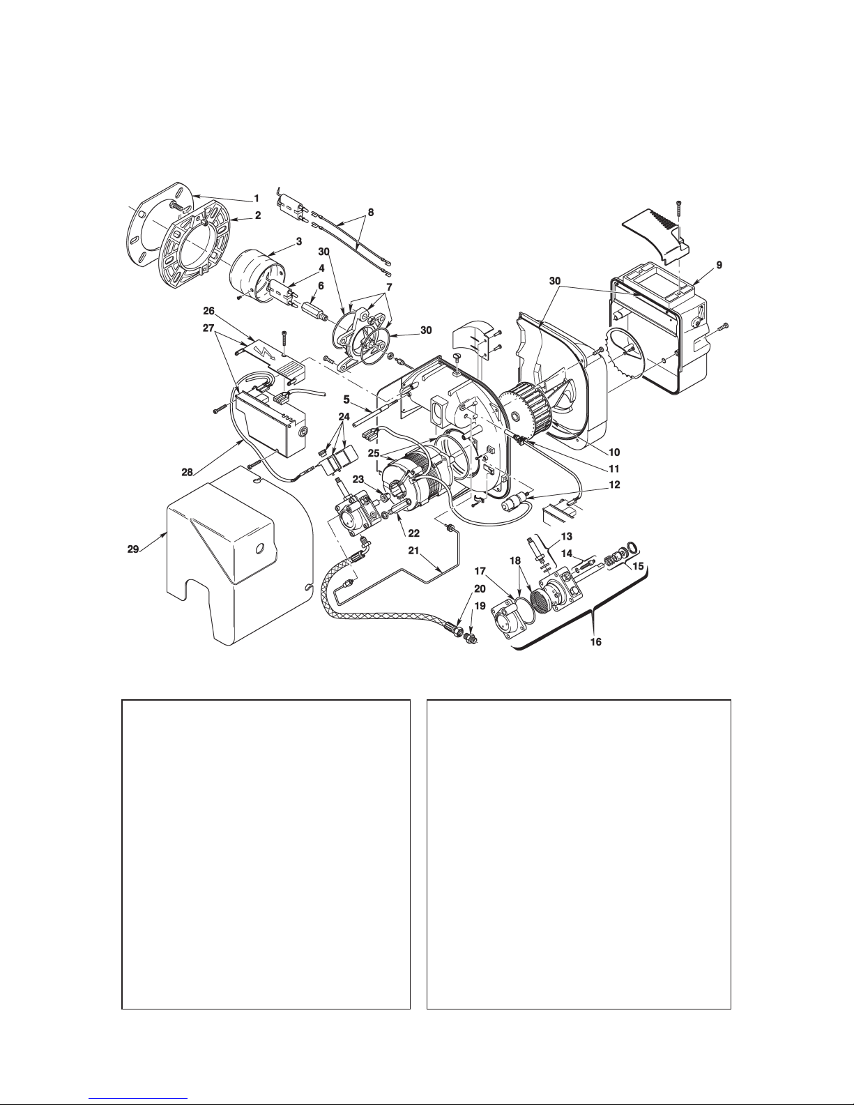
Page 64
13.0 Spares
13.1 RDB 2.2 Spares
No CODE
3514157 3514257 3514557
DESCRIPTION
1 3008512 • • • Gasket
2 3006384 • • • Flange
3 3002551 • Cup-Shaped Head
3 3001079 • Cup-Shaped Head
3 3020055 • Cup-Shaped Head
4 3008860 • • • Electrode Assembly
5 3008875 • • • Screw
6 3008861 • • • Nozzle Holder
7 3008862 • • • Collar
8 3008794 • • • High Voltage Lead
9 3008647 • • Air Damper Assembly
9 3008839 • Air Damper Assembly
10 3005788 • • • Fan
11 3007541 • • • PE Cell
12 3002837 • • • Capacitor 4.5µF
13 3007582 • • • Needle Valve
14 3008651 • • • Regulator
No CODE
3514157 3514257 3514557
DESCRIPTION
15 3000439 • • • Pump Seal
16 3008654 • • • Pump
17 3007162 • • • O-Ring
18 3008653 • • • Filter O-Ring
19 3003602 • • • Connector
20 3005720 • • • Flexible Oil Line
21 3008644 • • • Tube
22 3008876 • • • Pressure Gauge
23 3000443 • • • Joint
24 3008648 • • • Coil-Shell & Knob
25 3008650 • • • Motor
25 3002836 • • • Motor & Capacitor
26 3008649 • • • Protection
27 3008652 • • • Control Box 535RSE/LD
28 3008851 • • • Lead Coil
29 3008879 • • • Cover
30 3008878 • • • Kit Seals
Page 67
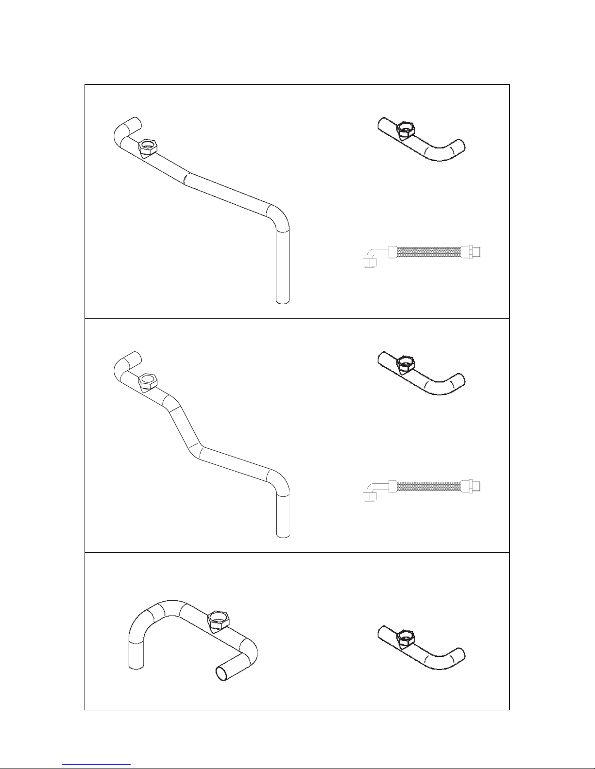
Page 65
13.2 Pipe Spares
UP70, UP90, US70 & US90 Models
KP70, KP90, KS70 & KS90 Models
UP120 & KP120 Models
From Boiler to Pump
3016
Pump Flow Pipe
3015
Pump Flow Pipe
3015
Expansion Vessel
Pressure Hose
3020
From Boiler to Pump
3017
From Boiler to Pump
3355
Pump Flow Pipe
3015
Expansion Vessel
Pressure Hose
3020
Page 68
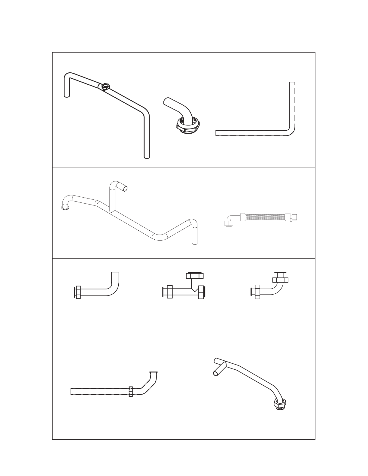
Page 66
13.2 Pipe Spares cont’d
UC70, UC90, KC70 & KC90 Models
From Boiler to Gate Valve
3097
CH Flow from Pump
3100
From Gate
Valve to Pump
3098
Return from both CH &
Plate Heat Exchanger
3219
From Heat Store to
Plate Heat Exchanger
1997
From Flowswitch to Mixing
Valve & Plate Heat Exchanger
1992
From Plate Heat
Exchanger to Mixing Valve
1994
DHW Flow from Mixing Valve
3101
From Strainer to Flowswitch & Filling Loop
3099
Expansion Vessel
Pressure Hose
3020
Page 69

Page 67
13.3 Short Parts List – Boiler
Part Description Code
Flow Switch 1476
Tank & Boiler Control Thermostat 2131
Boiler Limit Thermostat (Combi Models) 281
Tank Limit Thermostat 2126
Pump Overrun Thermostat 3108
Plate Heat Exchanger 599
Twin Head Pump 2130
15/60 Pump (for replacement head) 602
3 Pole Relay 1827
Auto Air Vent C/W Check Valve 614
Pressure Relief Valve 2132
Filling Loop 2133
Pressure Gauge 3019
Mixer Valve 1621
PCB Controller MK4 2419
12 Litre Pressure Vessel 2128
Single Pole Relay & Base 3074
Dual-Safe Thermostat for Non-Combi Models WDS2
Optional Programmer for Combi Models PC1
Optional Programmer for Non-Combi Models PU1
When ordering replacement casing panels it should be noted that due to the painting
process there may be some variation in colour.
Page 70

Page 68
14.0 Your Guarantee, Terms & Conditions
1. Warmflow Guarantees
The boiler, including all controls, plate heat
exchangers and associated equipment
contained within the boiler casing, the
burner and flue system if supplied by
Warmflow against defective parts and faulty
workmanship, for period of 12 months
from the date of installation, providing the
boiler is installed and commissioned in
accordance with the installation instructions
supplied with the boiler. The period of
guarantee will be increased to 24 months in
Great Britain providing:
• The guarantee registration form is fully
completed and returned to Warmflow
within 30 days from the date of
installation, or 90 days from the date
code stamped on the appliance.
• The boiler must be installed and
commissioned by a Warmflow or other
competent engineer, who is OFTEC
registered. Commissioning of the boiler
must be completed immediately after
the boiler is installed.
• The boiler must be serviced by a
Warmflow or other competent engineer,
who is OFTEC registered, 12 months
after the date of installation and
thereafter, at 12 monthly intervals.
NOTE: In Northern Ireland and the
Republic of Ireland the period of
guarantee can only be increased to
24 months through the purchase of an
extended warranty.
The water jacket and thermal store (in the
case of a combination boiler) for a total of 5
years from the appliance date code, subject
to the above conditions being complied
with.
Warmflow reserves the right to repair or
replace components within the guarantee
period at a time and location that is most
convenient to the company.
2. Conditions of Guarantee
The boiler must be installed, commissioned
and serviced in accordance with the
installation instructions supplied with the
boiler.
Warmflow will accept no liability for the
cost of repairs resulting from incorrect
installation, inadequate commissioning, lack
of regular maintenance, misuse, tampering
or repair by unqualified persons.
All repairs must be authorised in writing by
Warmflow prior to any work being carried
out. Unauthorised claims are not covered
by the guarantee.
Labour charges associated with the
replacement of heat exchangers or thermal
heat stores will be calculated on a sliding
scale depending on the boiler output up
to a set maximum. Contact Warmflow for
current prices.
Faults and any associated costs occurring
due to lack of fuel, power, water supply or
scale formation are not covered by these
guarantees.
Claims for consequential loss or damage
are not covered by these guarantees.
In the event of a breakdown please
contact your commissioning engineer
who should then contact our service
department whilst at your home, to
report the fault.
The statutory rights of the customer are not
affected by the guarantee.
NB: The nozzle supplied with the boiler is
deemed to be an expendable item and is
therefore excluded from the guarantee.
Page 71

Page 69
COMMISSION
Commission/Service Record Boiler Serial No |__|__|__|__|__|__|__|__|
In order that your boiler gives you many years of economical trouble free use and to validate the
warranty, this boiler must be commissioned upon installation and serviced annually. Contact Warmflow
for an approved engineer within your area.
SERVICE 1
SERVICE 3
SERVICE 2
SERVICE 5
SERVICE 4
SERVICE 7
SERVICE 6
SERVICE 9
SERVICE 8
Date of Commission ______________________
Company Name ______________________
Engineer Name ______________________
Engineer Signature ______________________
Telephone No ______________________
Date of 1st Service ______________________
Company Name ______________________
Engineer Name ______________________
Engineer Signature ______________________
Telephone No ______________________
Date of 3rd Service ______________________
Company Name ______________________
Engineer Name ______________________
Engineer Signature ______________________
Telephone No ______________________
Date of 2nd Service ______________________
Company Name ______________________
Engineer Name ______________________
Engineer Signature ______________________
Telephone No ______________________
Date of 5th Service ______________________
Company Name ______________________
Engineer Name ______________________
Engineer Signature ______________________
Telephone No ______________________
Date of 4th Service ______________________
Company Name ______________________
Engineer Name ______________________
Engineer Signature ______________________
Telephone No ______________________
Date of 7th Service ______________________
Company Name ______________________
Engineer Name ______________________
Engineer Signature ______________________
Telephone No ______________________
Date of 6th Service ______________________
Company Name ______________________
Engineer Name ______________________
Engineer Signature ______________________
Telephone No ______________________
Date of 9th Service ______________________
Company Name ______________________
Engineer Name ______________________
Engineer Signature ______________________
Telephone No ______________________
Date of 8th Service ______________________
Company Name ______________________
Engineer Name ______________________
Engineer Signature ______________________
Telephone No ______________________
Page 72

Page 70
Notes
Page 73

Page 71
Notes
Page 74

Page 72
Notes
Page 75
Page 76
 Loading...