

WarmFlow U120, U-Series UP 70, UP90, UP120, US70 Owner's Manual
...

Page 1
Contents Page
User Instructions .....................................................................................................................................................................
2
Combi Boiler Pre-Installation Requirements ........................................................................................................................
4
1.0 General Information
1.1 Introduction .....................................................................................................................................................
5
1.2 General Requirements .....................................................................................................................................
5
1.3 Combi General Requirements ..........................................................................................................................
6
1.4 Baffle Positioning .............................................................................................................................................
6
1.5 Components ...................................................................................................................................................
7
2.0 Technical Details
2.1 Combi Sequence of Operation Flow Chart ....................................................................................................17
2.2 Dimensions ...................................................................................................................................................18
2.3 Flue Options & Dimensions ............................................................................................................................
23
2.4 Technical Data ...............................................................................................................................................
24
3.0 Electricity Supply & Wiring Details
3.1 Dual-Safe Thermostat (Non-Combi Models) ..................................................................................................
33
3.2 RDB Burner Control Box ...............................................................................................................................
33
3.3 Combi Wiring Details .....................................................................................................................................
34
3.4 Installation of a Warmflow Combi Optional Programmer (PC1) .......................................................................
37
3.5 Remote Timers for Combis ............................................................................................................................
38
3.6 Optional Programmer (PU1) for Non-Combi Models ......................................................................................
39
4.0 Oil Supply
4.1 One Pipe Gravity System ...............................................................................................................................
43
4.2 Two Pipe System ...........................................................................................................................................
44
4.3 De-aerator System ........................................................................................................................................
44
4.4 One Pipe Lift System .....................................................................................................................................
45
5.0 Flues
5.1 Installation of Balanced Flues
.........................................................................................................................46
5.2 Conventional Flues ........................................................................................................................................
48
5.3 Low Level Balanced Flue Terminal Positions ..................................................................................................
48
6.0 Air Supply for Combustion & Ventilation
6.1 Open Flue Boilers ..........................................................................................................................................
50
6.2 Balanced Flue Boilers – Boilers in a Compartment .........................................................................................
50
7.0 Installation Requirements
7.1 General Requirements ...................................................................................................................................51
7.2 Sealed Systems ............................................................................................................................................
52
7.3 Combi Domestic Hot Water ...........................................................................................................................
53
8.0 Burners
8.1 RDB Burner ...................................................................................................................................................
54
8.2 Oil Pump .......................................................................................................................................................
54
8.3 Electrode Setting ...........................................................................................................................................
55
8.4 Burner Start-Up Cycle ...................................................................................................................................
55
8.5 Air Damper Adjustment .................................................................................................................................
55
9.0 Commissioning & Servicing
9.1 Commissioning
..............................................................................................................................................56
9.2 Servicing .......................................................................................................................................................
56
10.0 Burner Fault Finding
10.1 Riello RDB .....................................................................................................................................................
57
11.0 Combi Fault Finding
11.1 Central Heating .............................................................................................................................................
58
11.2 Domestic Hot Water ......................................................................................................................................
59
12.0 Optional Boiler Mounted Digital Timer
12.1 Operating Instructions ...................................................................................................................................
60
13.0 Spares
13.1 RDB 2.2 Spares ............................................................................................................................................
64
13.2 Pipe Spares ...................................................................................................................................................
65
13.3 Short Parts List – Boiler .................................................................................................................................
67
14.0 Your Guarantee, Terms & Conditions .....................................................................................................................
68
Commissioning/Service Record .............................................................................................................................69
Page 2
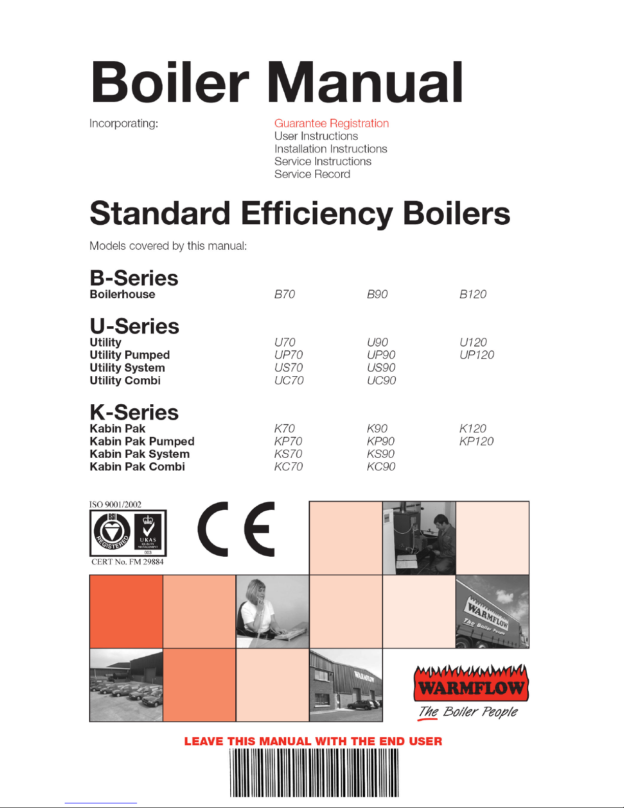
USER INSTRUCTIONS
Dual Thermostat
The radiator temperature is regulated via the
boiler control thermostat. The thermostat is user
adjustable from 55°C at its minimum setting (dial
‘0’) to 85°C at its maximum setting (dial ‘5’). In
order to provide an additional level of safety there
is a high limit thermostat which has a cut off point
of 110°C; this is factory set and is not adjustable.
If thermostat trips it needs to be reset manually.
High Limit Thermostat Reset
If the high level thermostat trip has operated,
remove the reset cover by using a coin or
screwdriver (turning anti clockwise) and press the
small red button now exposed. Do not press the
reset button while the boiler is still hot as this will
cause damage to the thermostat.
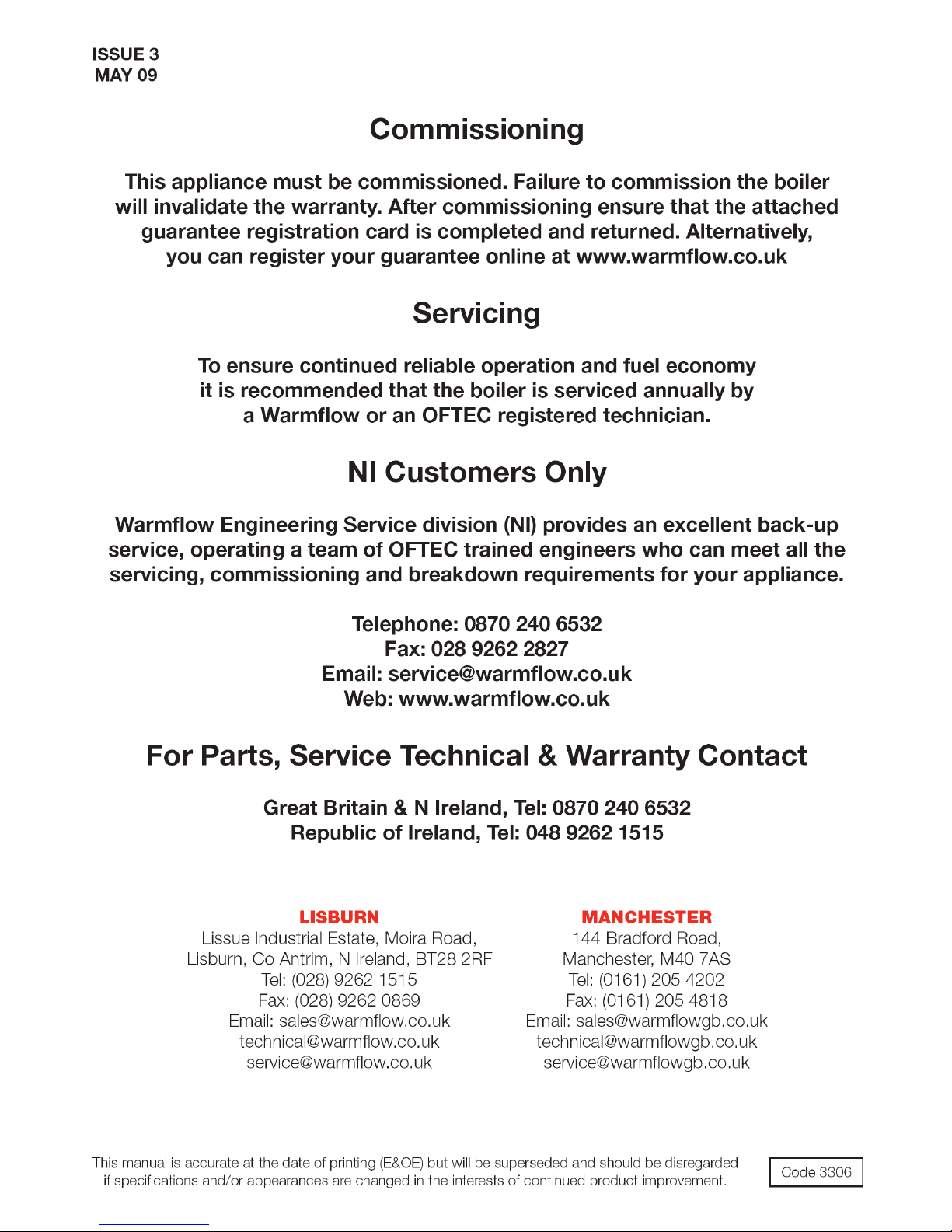
Burner Lockout
When the pressure jet oil fired burner stops after
failing to fire the red reset button will be illuminated.
This indicates that there is a fault or there is no
fuel getting to the burner. The house holder should
only reset the burner twice in succession. If the
burner continues to lockout contact Warmflow or
your service engineer.
System Pressure – System & Combi Boilers
When the boiler is connected to a sealed system
the system pressure should be periodically
checked. The minimum pressure, as indicated by
the black needle, is 0.5 bar when the boiler is cold
and 2.5 bar when the boiler is at normal operating
temperature. If the pressure is outside this range
contact Warmflow or your installer.
Control Thermostat
High
Limit
Reset
Notes
USER INSTRUCTIONS
Dual Thermostat
The radiator temperature is regulated via the
boiler control thermostat. The thermostat is user
adjustable from 55°C at its minimum setting (dial
‘0’) to 85°C at its maximum setting (dial ‘5’). In
order to provide an additional level of safety there
is a high limit thermostat which has a cut off point
of 110°C; this is factory set and is not adjustable.
If thermostat trips it needs to be reset manually.
High Limit Thermostat Reset
If the high level thermostat trip has operated,
remove the reset cover by using a coin or
screwdriver (turning anti clockwise) and press the
small red button now exposed. Do not press the
reset button while the boiler is still hot as this will
cause damage to the thermostat.
Control Thermostat
High
Limit
Reset
Reset
Notes
Burner Lock Out Reset
System Pressure
Page 3
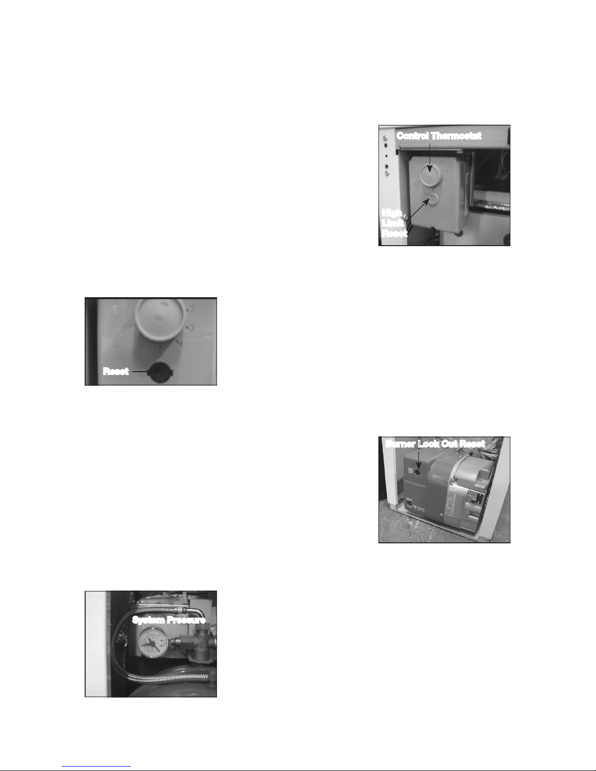
Filling Loop
If the system pressure falls below the minimum
(eg, removal of radiator for decorating purposes)
then the system should be topped up using the
filling loop valve. After the system has been topped
up the pressure gauge should read 1 bar when
the system is cold. The valve must be fully closed
and the filling loop flexible removed from the valve,
expect a small water loss from the pipe.
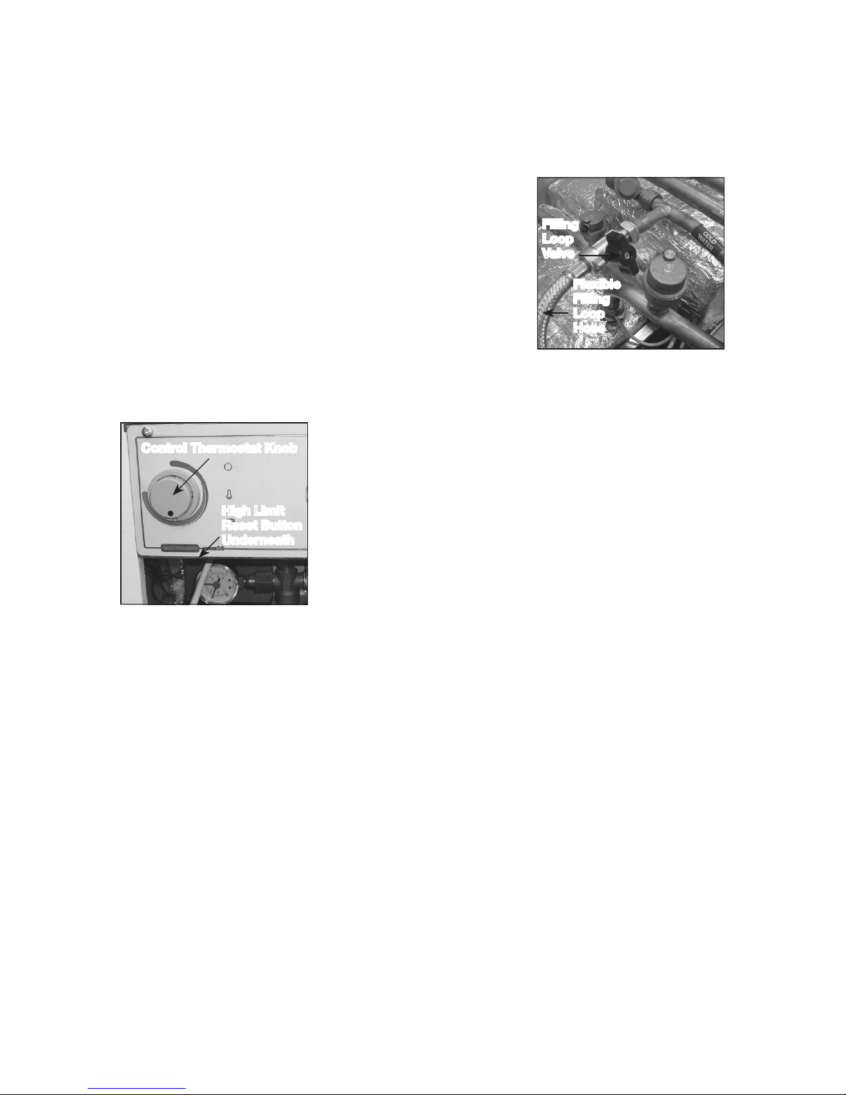
Combi Control Panel
The heating control thermostat is user adjustable
from 55°C to 85°C. In order to provide an
additional level of safety there is a high limit
thermostat which has a cut off point of 110°C;
this is factory set and is not adjustable. The high
limit thermostat is located under the control
panel to the left hand side, press button to reset.
As standard the panel is fitted with two on/off
selector switches to control hot water and central
heating. These switches can be replaced by the optional two channel digital
programmer, instructions for use are provided in the main boiler handbook.
This boiler must be serviced annually. Contact Warmflow for further
details.
In the event of a breakdown please contact your commissioning engineer
who should then contact our service department whilst at your home, to
report the fault.
High Limit
Reset Button
Underneath
Filling
Loop
Valve
Flexible
Filling
Loop
Hose
Control Thermostat Knob

Page 4
BEFORE FITTING A COMBI BOILER
THE INSTALLER MUST CHECK:
1. What the maximum hot water demand placed on the boiler is likely
to be. Not every installation is suitable for a Combi boiler. Systems
requiring very high hot water flow rates may be better suited with an
unvented cylinder.
2. That the mains are capable of supplying up to 24 litre/min with a
minimum dynamic pressure of 1.8 bar at the boiler. This is to ensure that
the boiler can achieve its maximum output. To protect the appliance
and to prevent excessive flow rates, a pressure reducing valve must be
fitted to limit the maximum supply pressure to 3 bar.
3. Where the mains water pressure is supplied via a borehole pump and
accumulator the pressure variation must not affect the thermostatic
mixer valve. Contact Warmflow for further details.
4. The hardness of the mains water supply. Systems with hard water must
be fitted with a suitable chemical scale preventer (eg Fernox Quantomat
or Combimate).
5. That the flow from any one hot water outlet does not exceed the
maximum recommended. This applies particularly to baths which are
usually fitted with larger taps and larger bore supply pipes. It may be
necessary to restrict the flow to these taps by reducing the bore of the
supply pipework (eg 15mm) or by fitting a restrictor into the pipework.
6. That any outlet when opened does not starve all the other outlets of hot
water. If more than one outlet is open at the same time then the total
flow from all the outlets should not exceed the maximum flow rate of
the boiler.
7. That any showers being supplied with hot water by the boiler are
compatible with this type of appliance.
It should be noted that the boiler has been factory fitted with an
18 litre/min flow restrictor.
The manufacturer’s guarantees are void if the appliance is not installed
and commissioned in accordance with the recommendations made
herein.

Page 5
1.0 General Information
1.1 Introduction
Note: All our domestic appliances have been independently tested and
accredited as exceeding the minimum SEDBUK efficiency levels required for
their type, in compliance with the Building Regulations Approved Document
L1A, L1B for England and Wales, the Building Standards (Scotland)
Regulations Section 6, Part F Northern Ireland and Part L Republic of
Ireland.
Warmflow standard efficiency boilers are designed for use only on fully pumped
(sealed or open-vented) heating systems and to burn Class C2 kerosene and
Class D gas oil. Note that with class D gas oil the flue MUST exhaust at more than
2m above the surrounding ground level. The low-level flue supplied as standard with
all Kabin Pak models is NOT suitable for Class D gas oil. Alternative options are
available – please contact Warmflow.
As standard the Combi and System boilers are fitted with a system expansion
vessel, circulating pumps, filling loop, pressure gauge and safety valve. An optional
7-day electronic programmer kit is also available for all Utility boiler models.
The Combi can provide at mains pressure domestic hot water without the need for
a storage cylinder.
The manufacturer’s guarantees are void if the appliance is not installed and
commissioned in accordance with the recommendations made herein.
1.2 General Requirements
The installation of the boiler must be in accordance with the following regulations.
BS5410 : PART 1 Code of practice for oil firing.
BS5449 : PART 1 Forced circulation hot water systems.
BS7593 : Treatment of water in domestic hot water central heating systems.
Current Building Regulations Part J England and Wales
Section 3 Scotland
Part L Northern Ireland
Part J Republic of Ireland
Current IEE Regulations
BS7074 : PART 1 Application Selection & Installation of Expansion Vessels
The heating system should be installed by a competent installer in accordance with
the recommendations laid down by HVCA, OFTEC and sound engineering practice.
In order to comply with the building regulations OFTEC forms CD10 for
installations and CD11 for commissioning should be left with the customer.
Alternatively the installation can be inspected and approved by a building
control officer. CD10 and CD11 forms are available from OFTEC on
Tel: 0845 658 5080, Fax: 0845 658 5181.
Page 6
1.3 Combi General Requirements
The boiler will have a DHW priority when both domestic hot water (DHW) and central
heating (CH) are selected. So if the flow switch is closed or the heat store has not
been satisfied the entire output of the boiler is directed to DHW before the boiler will
switch over to CH. When fully cold it can take up to 20 minutes for the heat store of
a 90,000 Btu/h Combi to be satisfied, and slightly longer for a 70,000 Btu/h Combi.
After a draw-off of 120L at 24L/min, with an average temperature rise of 32°C, the
thermal store of a 90,000 Btu/h Combi has a recovery time of approximately 7 mins.
A 70,000 Btu/h Combi will take slightly longer to recover.
Note: If HW has not been selected no hot water can be produced even if the heat
store is up to temperature.
1.3.1 Pump Overrun
Where there is a build up of excess heat in the boiler heat exchanger and the central
heating has not been selected then the pump overrun thermostat will operate. The
excess heat will then be pumped into the heat store. Once the temperature has
fallen in the boiler and the pump overrun stat is satisfied or the central heating pump
starts to operate, then the hot water pump will stop.
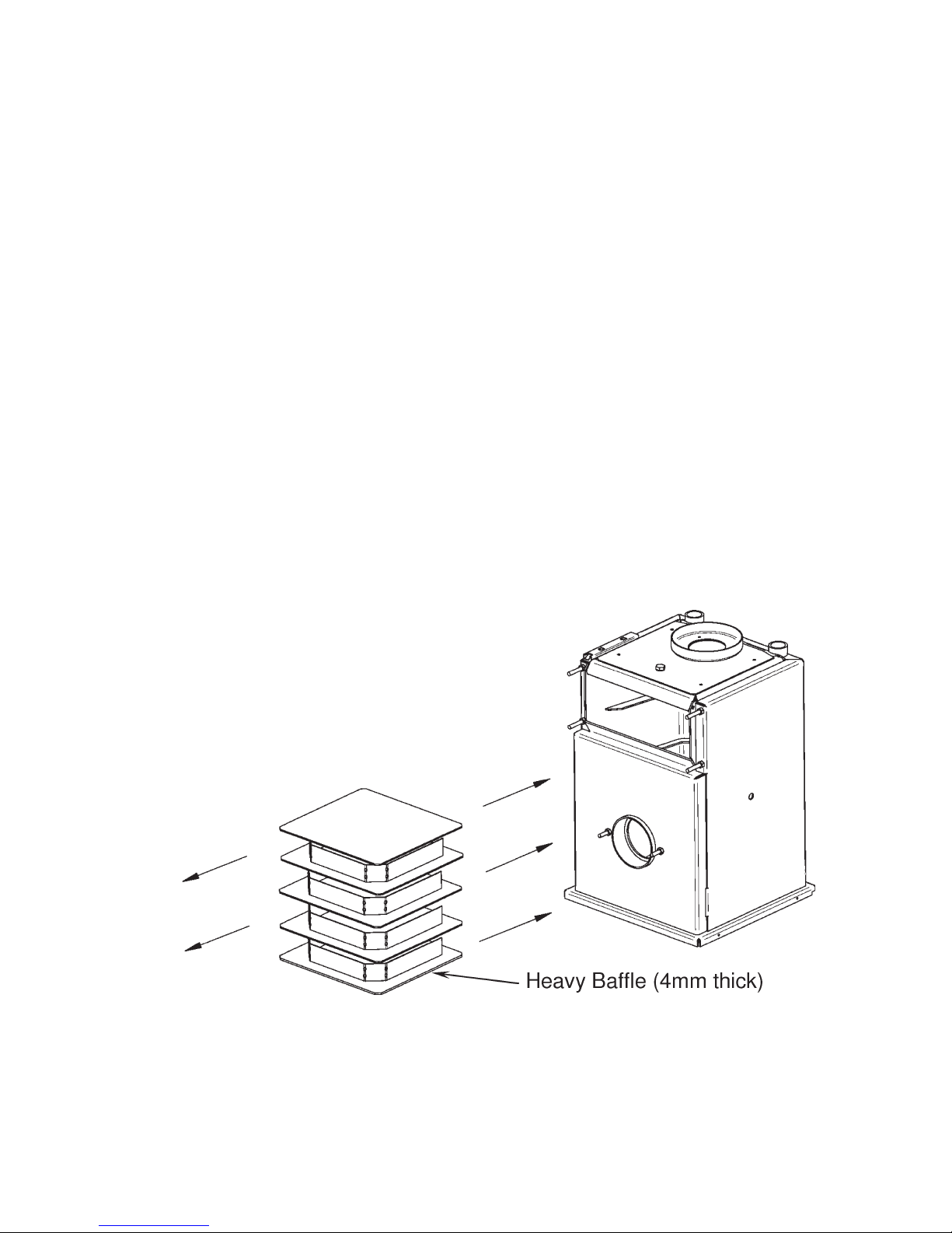
1.4 Baffle Positioning
The heat exchanger baffles consist of one heavy baffle stack (4mm thick) at the
bottom, 3 lighter baffle stacks (3mm thick) in the middle and 1 baffle plate (3mm
thick) at the top. Upon installation or after servicing, ensure the baffles are in the
correct order and correctly stacked.
Page 7
1.5 Components
1.5.1 B-Series Boilerhouse – Casing Components
1. Boiler Assembly
with Casing
2. Service Door
Cover (removable)
1.5.2 B-Series Boilerhouse (B70, B90 & B1) – Key Components
1. Heat Exchanger
with Casing
2. Service Door Cover
3. Heat Exchanger Baffles
4. ‘Dual-Safe’ Thermostat
5. Service Door
6. Riello RDB 2.2 Burner
7. Flue Ring
8. Heating Flow
Connection
9. Heating Return
Connection
1
2
1
2
3
4
5
6
7
9
8
Page 8
1.5.3 B-Series Boilerhouse (B120) – Key Components
8
1. Heat Exchanger
Assembly with Casing
2. Service Door Cover
3. Secondary Exchanger
Inspection Lid
4. Primary Exchanger Baffles
5. ‘Dual-Safe’ Thermostat
6. Service Door
7. Riello RDB 2.2 Burner
8. Flue Opening
9. Heating Flow
Connection x 2
10. Heating Return
Connection
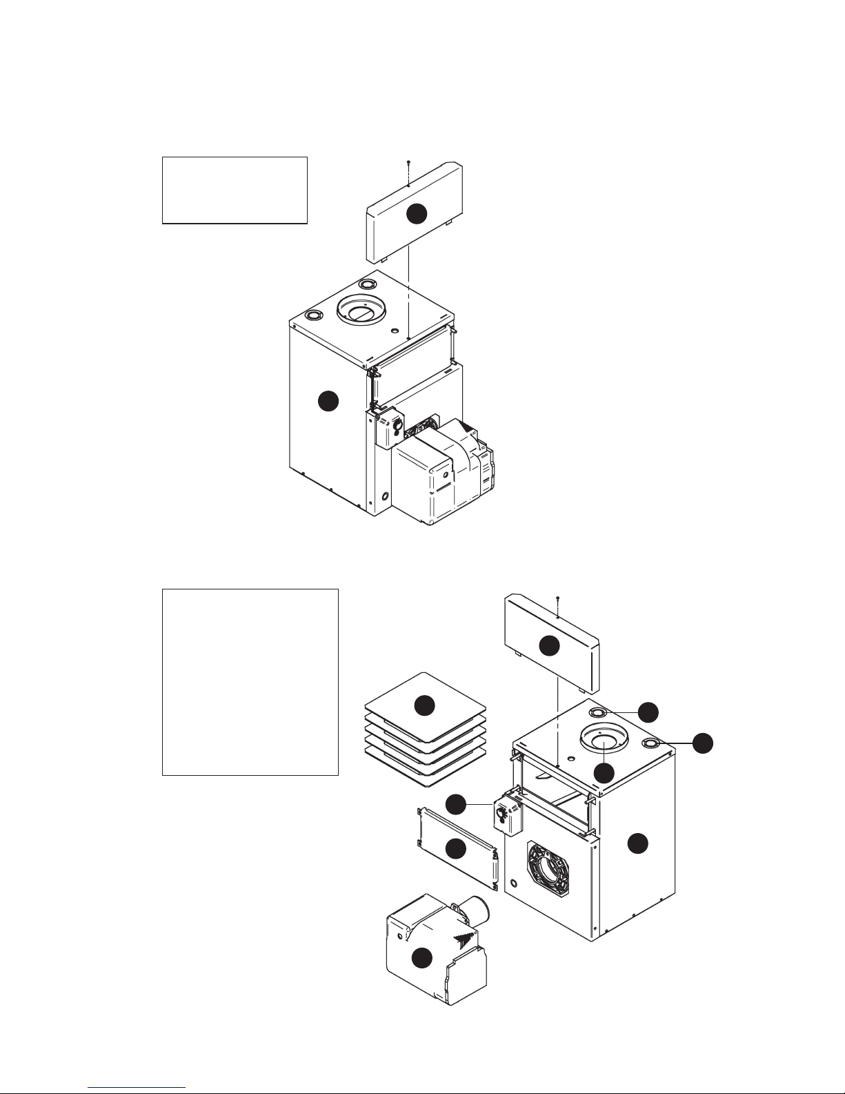
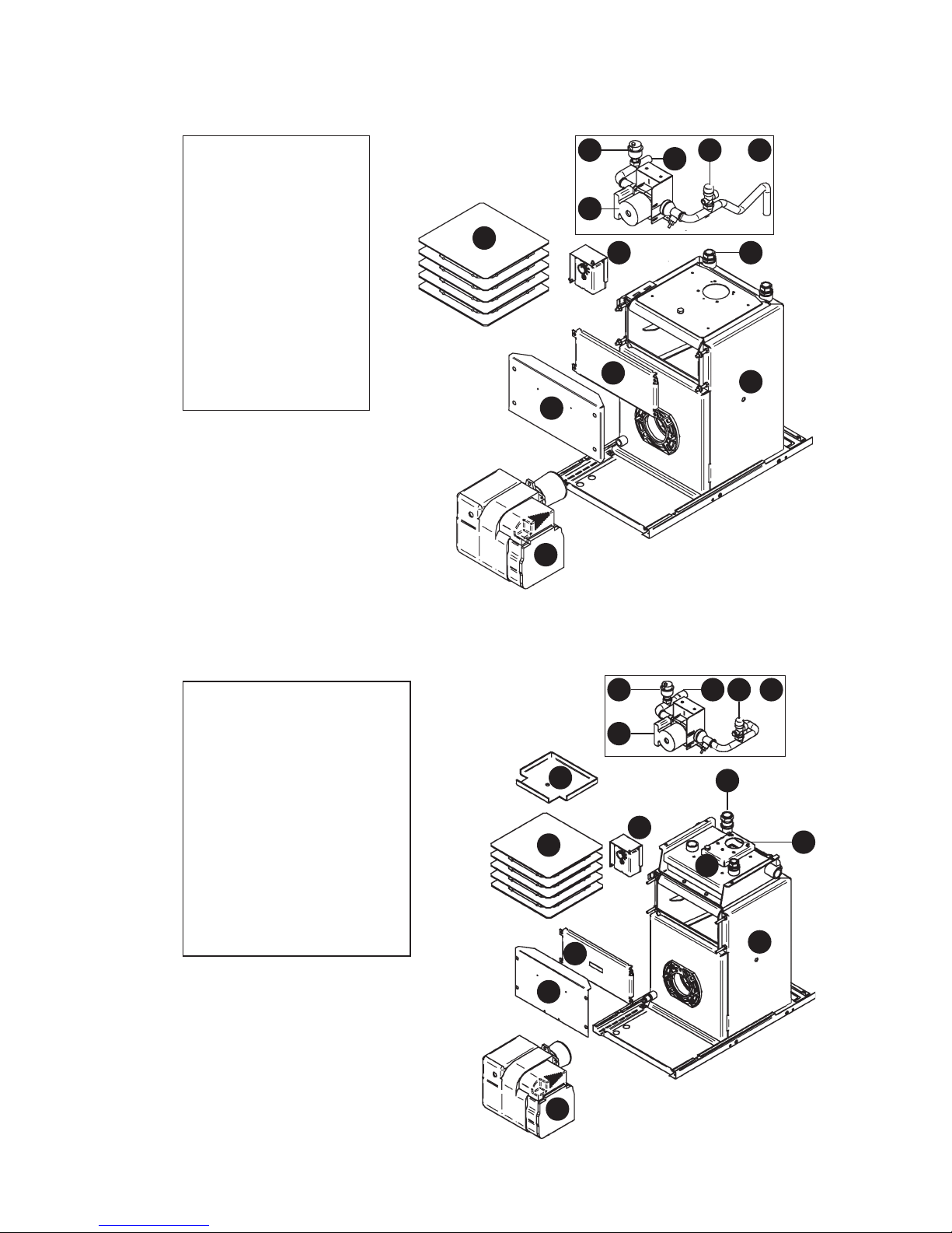
1.5.4 U-Series Utility – Casing Components
1. Boiler Assembly
2. Top Casing (removable)
3. Rear Casing
4. Side Casing
5. Front Casing (removable)
1
2
3
4
5
6
7
9
10
1
2
3
4
5
Page 9
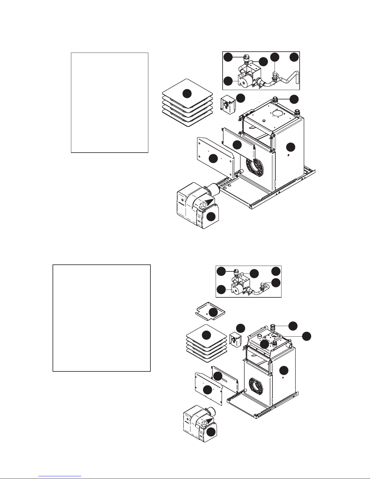
1.5.5 U-Series Utility – Pre-Wired (U70 & U90) – Key Components
1. Heat Exchanger
2. ‘Dual-Safe’
Thermostat
3. Heat Exchanger
Baffles
4. Service Door
5. Service Door
Cover
6. Riello RDB
2.2 Burner
7. Flue Opening
8. Heating Flow
Connection
9. Heating Return
Connection
1
4
6
7
3 2
9
5
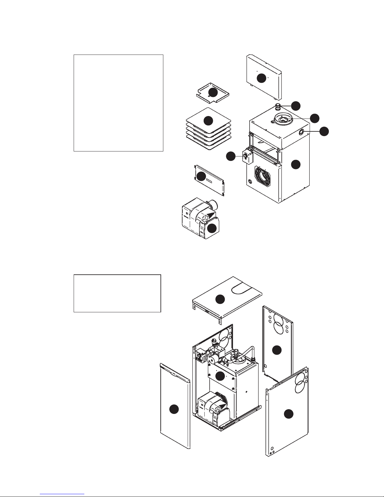
1.5.6 U-Series Utility – Pre-Wired (U120) – Key Components
1. Primary Heat
Exchanger
2. Secondary Heat
Exchanger
3. ‘Dual-Safe’ Thermostat
4. Secondary Exchanger
Inspection Lid
5. Primary Exchanger
Baffles
6. Service Door
7. Service Door Cover
8. Riello RDB 2.2 Burner
9. Flue Opening
10. Heating Flow
Connection x 2
11. Heating Return
Connection
1
2
3
4
8
10
9
5
6
7
10
11
8
Page 10
1
8
10
6
7
4 2
11
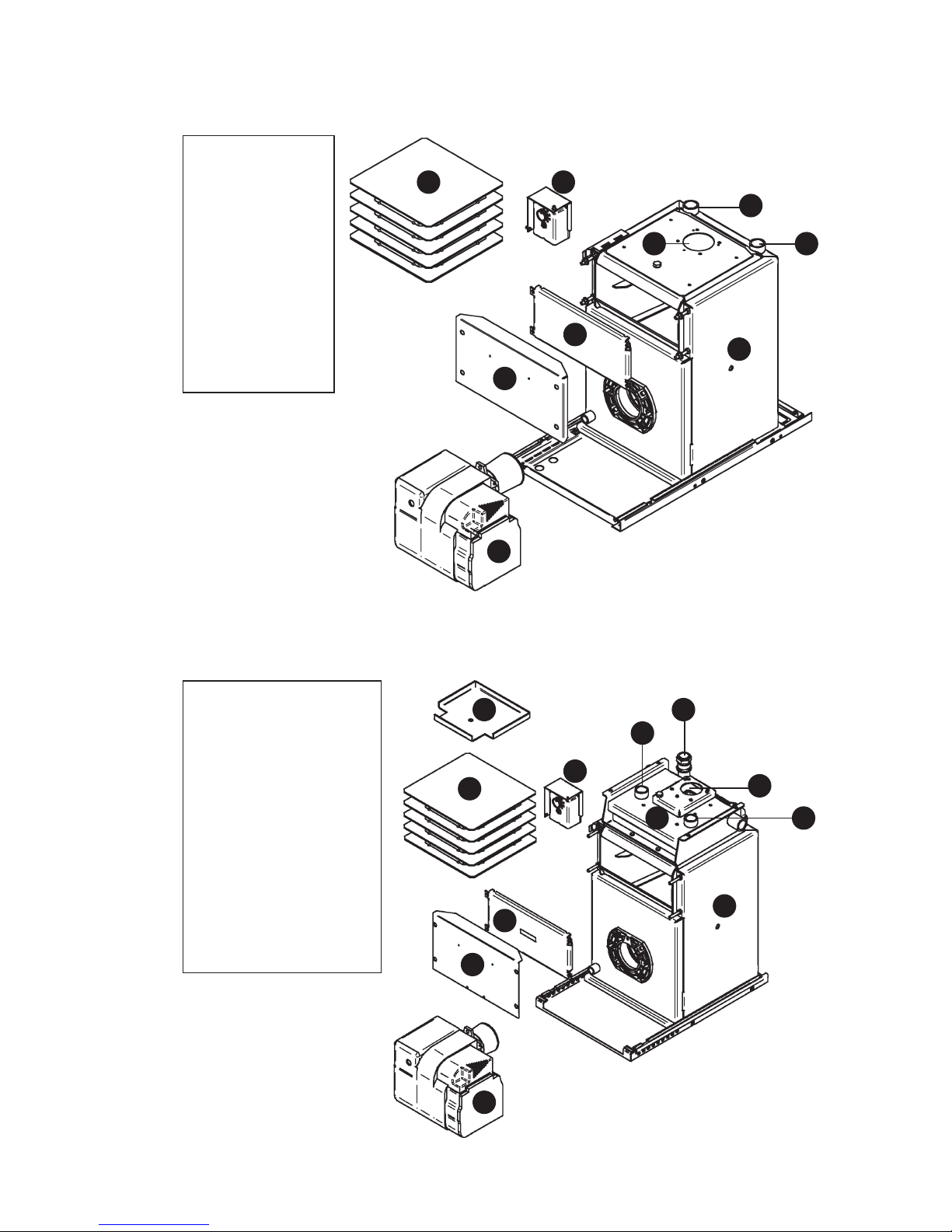
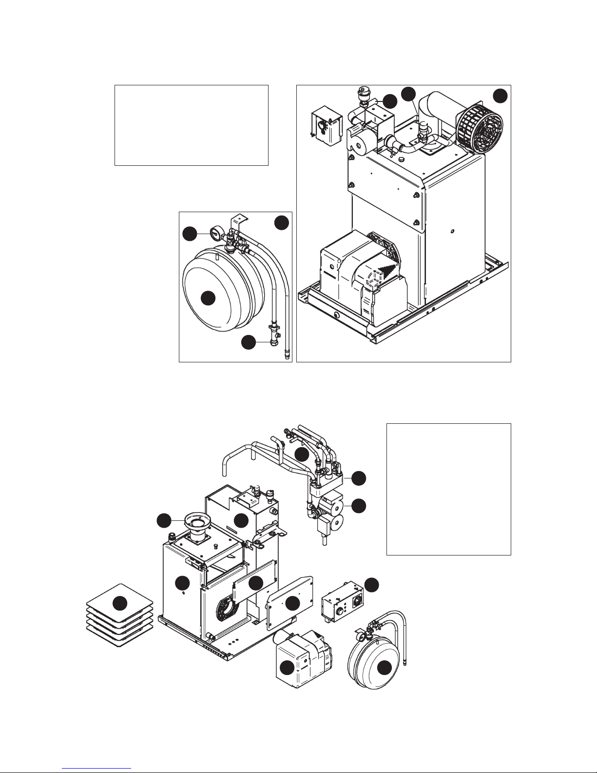
1.5.7 U-Series Utility – Pumped (UP70 & UP90) – Key Components
1. Heat Exchanger
2. Pipework Assembly
3. Pressure Relief Valve
4. Auto Air Vent
5. Circulating Pump
6. ‘Dual-Safe’ Thermostat
7. Heat Exchanger Baffles
8. Service Door
9. Service Door Cover
10. Riello RDB 2.2 Burner
11. Heating Flow
Connection
12. Heating Return
Connection
5
3
9
1. Primary Heat Exchanger
2. Secondary Heat Exchanger
3. Pipework Assembly
4. Pressure Relief Valve
5. Circulating Pump
6. Auto Air Vent
7. ‘Dual-Safe’ Thermostat
8. Secondary Exchanger
Inspection Lid
9. Primary Exchanger Baffles
10. Service Door
11. Service Door Cover
12. Riello RDB 2.2 Burner
13. Flue Opening
14. Heating Flow Connection
15. Heating Return Connection
1
8
7
5
2
6 3
15
1.5.8 U-Series Utility – Pumped (UP120) – Key Components
14
4
9
10
11
12
12
13
Page 11
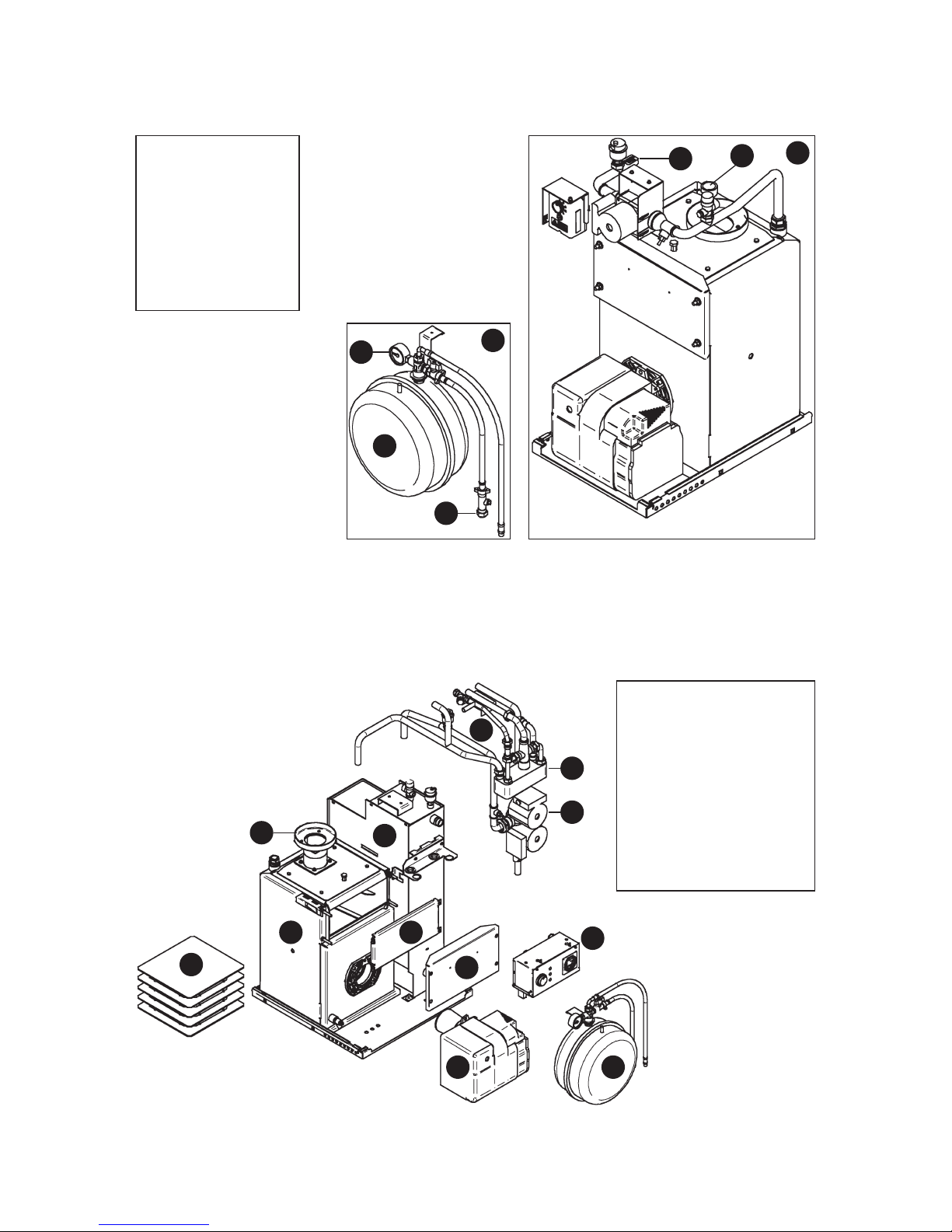
1.5.9 U-Series Utility – System (US70 & US90) – Key Components
1. Pumped (UP)
Boiler Assembly
2. System Kit (SK1)
3. Pressure Gauge
4. Expansion Vessel
5. Filling Loop
6. Heating Flow
Connection
7. Heating Return
Connection
4
3
5
2
1
6
7
1.5.10 U-Series Utility – Combi (UC70 & UC90) – Key Components
1. Heat Exchanger
2. Heat Store
3. Pipework Assembly
4. Plate Heat Exchanger
5. Twin Head Pump
6. Service Door
7. Service Door Cover
8. Control Panel
9. Expansion Vessel
10. Riello RDB 2.2 Burner
11. Heat Exchanger Baffles
12. Flue Ring
1
2
3
4
5
8
9
6
7
10
11
12
Page 12
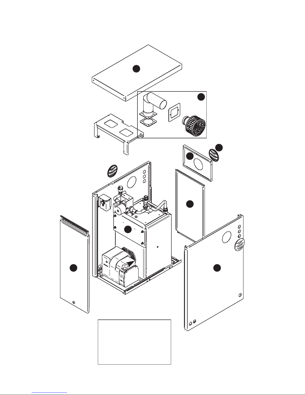
1.5.11 K-Series Kabin Pak – Casing Components
1. Boiler Assembly
2. Top Casing (removable)
3. Flue Assembly (removable)
4. Rear Flue Casing
5. Blanking Plug (removable)
6. Rear Casing (removable)
7. Side Casing
8. Front Casing (removable)
1
2
3
4
5
6
78
Page 13
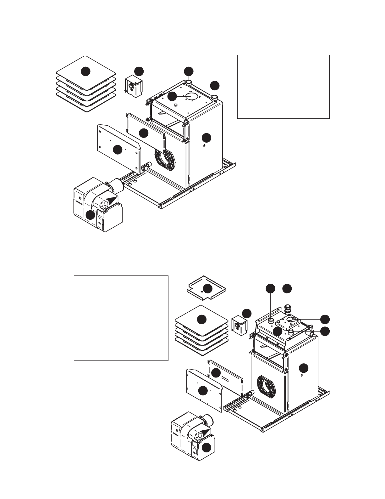
1.5.12 K-Series Kabin Pak – Pre-Wired (K70 & K90) – Key Components
1. Heat Exchanger
2. ‘Dual-Safe’ Thermostat
3. Heat Exchanger Baffles
4. Service Door
5. Service Door Cover
6. Riello RDB 2.2 Burner
7. Flue Opening
8. Heating Flow Connection
9. Heating Return Connection
1
23
5
4
6
7
8
9
1.5.13 K-Series Kabin Pak – Pre-wired (K120) – Key Components
1. Primary Heat Exchanger
2. Secondary Heat Exchanger
3. ‘Dual-Safe’ Thermostat
4. Secondary Exchanger
Inspection Lid
5. Primary Exchanger Baffles
6. Service Door
7. Service Door Cover
8. Riello RDB 2.2 Burner
9. Flue Opening
10. Heating Flow Connection x 2
11. Heating Return Connection
1
2
3
4
5
6
7
8
1110
10
9
Page 14
1.5.14 K-Series Kabin Pak – Pumped (KP70 & KP90) – Key Components
1
8
11
5
6
7
9
10
12
3 2
1. Heat Exchanger
2. Pipework Assembly
3. Pressure Relief Valve
4. Auto Air Vent
5. Circulating Pump
6. ‘Dual-Safe’
Thermostat
7. Heat Exchanger
Baffles
8. Service Door
9. Service Door Cover
10. Riello RDB 2.2 Burner
11. Heating Flow
Connection
12. Heating Return
Connection
1.5.15 K-Series Kabin Pak – Pumped (KP120) – Key Components
1. Primary Heat Exchanger
2. Secondary Heat Exchanger
3. Pipework Assembly
4. Pressure Relief Valve
5. Circulating Pump
6. Auto Air Vent
7. ‘Dual-Safe’ Thermostat
8. Secondary Exchanger
Inspection Lid
9. Primary Exchanger Baffles
10. Service Door
11. Service Door Cover
12. Riello RDB 2.2 Burner
13. Flue Opening
14. Heating Flow Connection
15. Heating Return Connection
4
1
2
7
8
9
10
11
12
6
5
14 4 3
15
13
Page 15
1.5.16 K-Series Kabin Pak – System (KS70 & KS90) – Key Components
1. Pumped (KP) Boiler Assembly
2. System Kit (SK1)
3. Pressure Gauge
4. Expansion Vessel
5. Filling Loop
6. Heating Flow Connection
7. Heating Return Connection
1.5.17 K-Series Kabin Pak – Combi (KC70 & KC90) – Key Components
1. Heat Exchanger
2. Heat Store
3. Pipework Assembly
4. Plate Heat Exchanger
5. Twin Head Pump
6. Service Door
7. Service Door Cover
8. Control Panel
9. Expansion Vessel
10. Riello RDB 2.2 Burner
11. Heat Exchanger Baffles
12. Flue Ring
3
5
4
2
1
6
7
1
2
3
4
5
6
7
8
910
11
12
Page 16
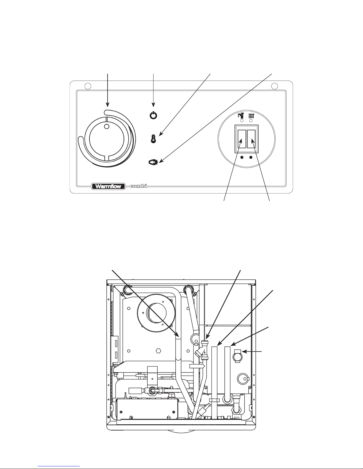
1.5.18 Combi Control Panel Layout
Control
Thermostat
Mains On
Lamp (Green)
High Limit Tripped
Lamp (Yellow)
Burner Lockout
Lamp (Red)
HW On/Off
Switch
CH On/Off
Switch
High Limit Thermostat Reset
(Underneath)
1.5.19 Combi Pipe Layout (UC & KC Models)
Central Heating
Return (22mm Copper)
Cold Water
Mains (15mm)
Domestic Hot
Water (22mm)
Central Heating
Flow (22mm)
Pressure Relief
Discharge (15mm)

Page 17
2.0 Technical Details
2.1 Combi Sequence of Operation Flow Chart
Power
On
Timer Calling
For Heat
HW
Selected
Flow Switch
Closed
DHW Tank
Stat Satisfied
CH
Selected
CH Pump
Only Runs
Room Stat
Satisfied
Boiler Stat
Satisfied
Boiler Limit
Stat Tripped
Burner
Fires
DHW Pump
Only Runs
HW Limit
Stat Satisfied
Boiler Limit
Stat Tripped
Burner
Fires
Burner
Stops
Press
Reset Button
Press
Reset Button
Pump Overrun
Stat Satisfied
DHW Pump
Only Runs
YES
YES
YES
NO
YES
NO
YES
YES
YES
NO
NO
NO
NO
NO
NO
YES
YES
YES
YES
YES
YES NO
NO
NO
Page 18
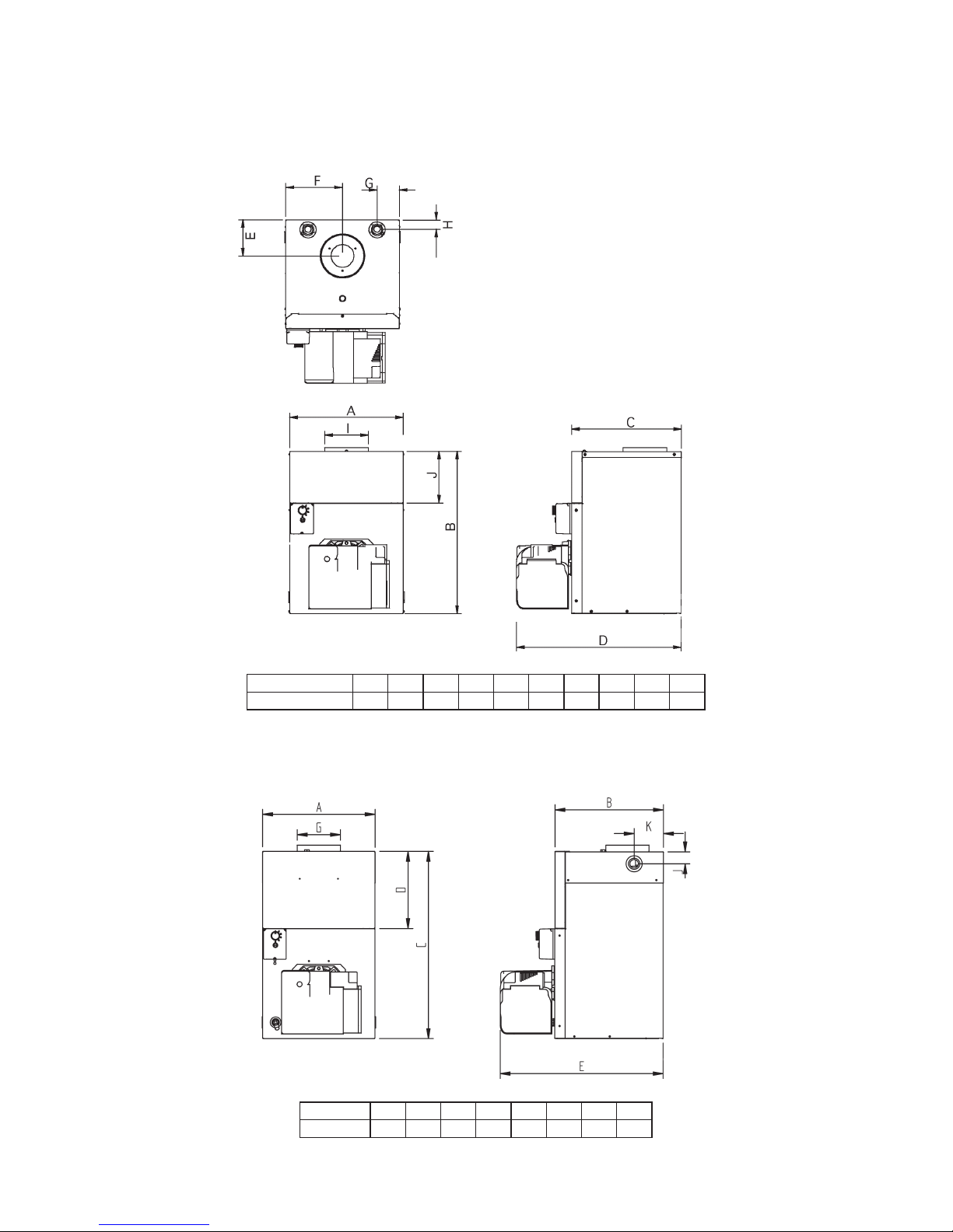
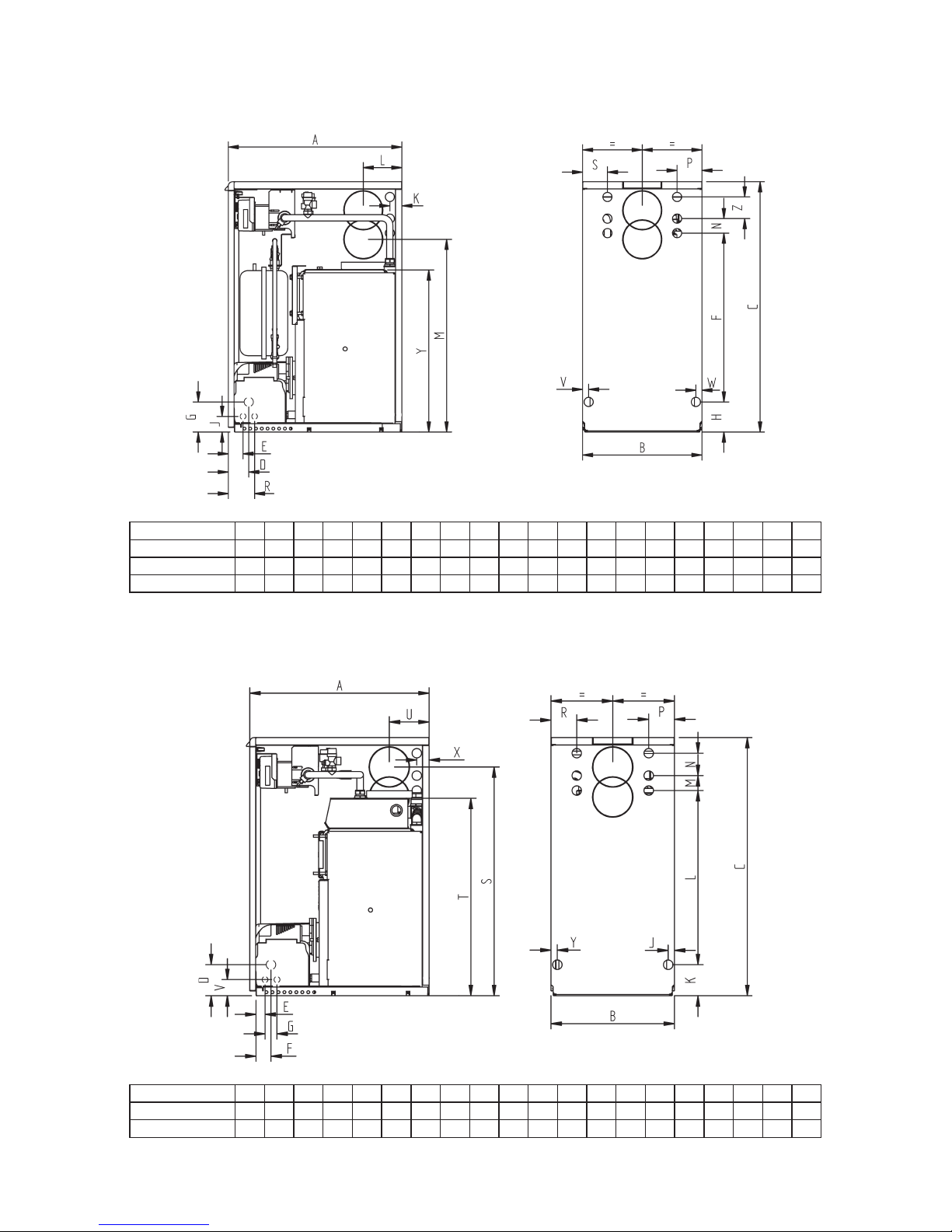
2.2 Dimensions
2.2.1 B-Series Boilerhouse (70 & 90 Output Models)
JHGFEDCBAMODEL
B70 / B90 / B1 396 573 383 574 127 198 78 32 183
I
152
2.2.2 B-Series Boilerhouse (120 Output Model)
KJGEDCBAMODEL
B120 397 383 662 273 575 152 42 103
Page 19
2.2.3 U-Series Utility (70 & 90 Output Non-Combi Models)
RPNMLKJHGFEDCBAMODEL
U70 & U90 600 413 865 71 51 583 104 104 54 42 134 666 50 86 91
UP70 & UP90
US70 & US90
S86V21W21Y
560Z75
600 413 865 71 51 583 104 104 54 42 134 666 50 86 91 86 21 21 560 75
600 413 865 71 51 583 104 104 54 42 134 666 50 86 91 86 21 21 560 75
2.2.4 U-Series Utility (120 Output Models)
RPNMLKJGFEDCBAMODEL
U120 600 413 865 104 30 50 40 21 104 583 50 75 86 86
UP120
S
766T662V134 54
X Y
42 21
U
600 413 865 104 30 50 40 21 104 583 50 75 86 86 766 662 134 54 42 21
Page 20
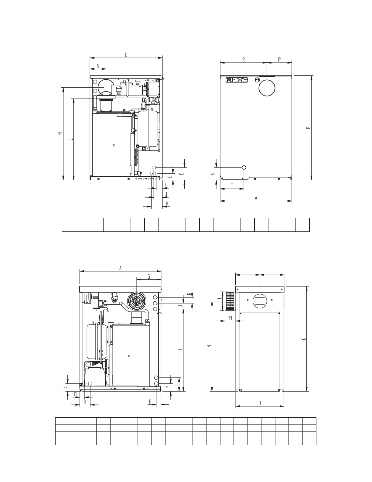
2.2.6 K-Series Kabin Pak (K, KP & KS Models)
2.2.5 U-Series Utility (UC Models)
RPNMLKJHEDCBAMODEL
UC70 & UC90 595
S T
865 600 54 104 51 71 91 674 766 134 207 388 104 197
RPNMLKJHGFEDCBAMODEL
K70 & K90 700
S
KP70 & KP90
KS70 & KS90
413 900 40 67 40 210 705 50 50 160 93 773 67 90 117
700 413 900 40 67 40 210 705 50 50 160 93 773 67 90 117
700 413 900 40 67 40 210 705 50 50 160 93 773 67 90 117

Page 21
2.2.7 K-Series Kabin Pak (120 Output Models)
PONMLKJHGFEDCBAMODEL
K120 700
KP120
I
413 900 40 67 117 705 50 50 67 40 773 160 210 50 90
700 413 900 40 67 117 705 50 50 67 40 773 160 210 50 90
2.2.8 K-Series Kabin Pak Base Tray (K, KP & KS Models)
 Loading...