

WarmFlow Solar SHP20, Solar SHP30 System Manual

System Manual
Incorporating: Installation Instructions
Commissioning Instructions
Maintenance Instructions
Guarantee Registration
Solar Thermal Systems
European Solar Keymark Approved
Products covered by this manual:
Solar SHP20 SHP30
Heat pipe vacuum tube collectors and accessories
LEAVE THIS MANUAL WITH THE END USER
Q12-027 rev 02 May ‘10


1
CONTENTS
1 General Information ..................................................................................................... 2
1.1 Warnings ..................................................................................................................... 2
1.2 Information ................................................................................................................... 3
1.3 Product Conformity ...................................................................................................... 3
2 Technical Characteristics ............................................................................................ 4
2.1 Technical Data ............................................................................................................. 4
2.2 Key Components ......................................................................................................... 5
2.3 Circuit Diagrams .......................................................................................................... 7
2.4 Pipework and Expansion Vessel Sizing ....................................................................... 8
2.5 Collector Pressure Drop ............................................................................................... 9
3 Installation ...................................................................................................................10
3.1 General Requirements ................................................................................................10
3.2 Tiled Roof Installation .................................................................................................10
3.2.1 Assemble pitched roof brackets ........................................................................................... 10
3.2.2 Install pitched roof brackets .................................................................................................. 11
3.2.3 Install support frame and manifold ....................................................................................... 12
3.2.4 Connect manifold pipework .................................................................................................. 13
3.3 Slate Roof Installation .................................................................................................14
3.3.1 Install slate roof brackets ...................................................................................................... 14
3.3.2 Install support frame ............................................................................................................. 15
3.3.3 Connect manifold pipework .................................................................................................. 15
3.4 Dual-line Pump Station Installation .............................................................................16
3.4.1 Mount pump station .............................................................................................................. 16
3.4.2 Connect pump station pipework ........................................................................................... 16
3.5 Electrical Installation ...................................................................................................17
3.5.1 Mount controller .................................................................................................................... 17
3.5.2 Connect external wiring centre ............................................................................................. 17
3.5.3 Connect back-up heat source .............................................................................................. 18
4 Commissioning ...........................................................................................................19
4.1 System Filling & Flushing ............................................................................................19
4.1.1 Check expansion vessel pre-charge .................................................................................... 19
4.1.2 Calculate system volume ..................................................................................................... 19
4.1.3 Connect filling station ........................................................................................................... 19
4.1.4 Flush system ........................................................................................................................ 20
4.1.5 Fill system ............................................................................................................................. 20
4.2 Pressure Testing .........................................................................................................21
4.2.1 Pressurise and inspect system ............................................................................................. 21
4.2.2 Set system pressure ............................................................................................................. 21
4.3 Sensor Installation ......................................................................................................21
4.4 Heat Pipe Tube Installation .........................................................................................22
4.4.1 Insert tube into manifold ....................................................................................................... 22
4.5 Circuit Flow Commissioning ........................................................................................23
4.5.1 Set pump speed ................................................................................................................... 23
4.5.2 Set flow adjuster ................................................................................................................... 23
5 Maintenance ................................................................................................................24
5.1 Periodic System Check ...............................................................................................24
5.2 Annual Maintenance ...................................................................................................24
5.2.1 Check installation ................................................................................................................. 24
5.2.2 Check fluid health ................................................................................................................. 24
5.2.3 Check performance .............................................................................................................. 24
5.2.4 Annual service checklist ....................................................................................................... 25
6 Product Guarantee ......................................................................................................26
7 Installation Notes ........................................................................................................27
8 Guarantee Registration ...............................................................................................29

2
1 GENERAL INFORMATION
1.1 Warnings
In order to qualify for the product guarantee the equipment MUST be correctly
commissioned as described herein and the guarantee registration section at the back of
this manual completed and returned.
Failure to commission and register the product may invalidate ALL guarantees.
This equipment must only be installed and commissioned by professionally qualified
personnel in accordance with current laws and standards and in line with the manufacturer’s
instructions. It is recommended that the system is installed by a competent installer such as
those registered under the Microgeneration Certification Scheme (MCS) in the United
Kingdom or with Sustainable Energy Ireland (SEI) in the Republic of Ireland.
The installation must comply with the requirements of:
- the Building Regulations
- current IEE Wiring Regulations or ETCI rules for electrical installations
Where no specific instructions are given, reference should be made to the relevant European
Standards.
This equipment must be used solely for the purpose for which it was designed and
manufactured – indirect heating of stored water (e.g. domestic hot water production).
Any other use is deemed improper and as such dangerous. The manufacturer accepts no
liability for damage or injury to persons or animals caused as a result of errors in the
installation and/or use of the equipment, or through non-compliance with current local and
national standards and/or the manufacturer’s instructions.
This equipment is only suitable for use in a sealed solar thermal system filled with the system
fluid supplied or specifically recommended by the manufacturer. The means of heating
domestic hot water (DHW), a swimming pool or other medium must be via a suitable heat
exchanger, for example the coil of a DHW storage cylinder.
This instruction manual forms an integral and essential part of the equipment and must be
kept in a safe place, available for future reference. This manual, along with the
commissioning and service records and proof of purchase, must be left with the end user.
It is essential that the heat pipe tubes are protected from overheating prior to installation.
NEVER leave uninstalled heat pipe tubes exposed to the sun.
Only unpack and install the heat pipe tubes after the rest of the system had been flushed,
filled and pressure tested and the system is ready to be brought into operation i.e. the DHW
storage cylinder is in use or the swimming pool has been filled.
If for any long periods there will be no heat load on the system (e.g. property unoccupied or
swimming pool emptied) the solar collector must either be covered or the heat pipe tubes
removed. If installing the collector onto a new-build property, DO NOT install the tubes until
the property is, or is about to become, occupied.
Due to the high temperatures that may be generated by a solar installation it is
recommended that a mixing valve be fitted to the hot water outlet from a domestic hot water
storage cylinder in order to limit the domestic hot water temperature. A setting of 60ºC is
recommended.

3
1.2 Information
Suitable personal protective equipment (e.g. hand and eye protection) must be used when
handling glass tubes. Avoid scratching or knocking the tubes and take care to protect the
teat at the base of the tube.
After removing the packaging, check that the equipment has not been damaged. In case of
doubt, do not attempt to install the equipment. Contact the supplier immediately to report the
damage. Packaging materials must not be left within reach of children as these items may
constitute a hazard and should be disposed of responsibly.
In case of a fault and/or malfunction in the equipment, shut the system down and isolate the
electrical supply. Contact your installer for advice.
In order to maintain the efficient and safe operation of this equipment it must be serviced
annually by professionally trained personnel in line with the manufacturer’s instructions.
The equipment can be regarded as electrically safe when connected to an effective earthing
system installed in accordance with the requirements of current regulations. This
fundamental safety requirement must be checked and verified. In case of doubt, have the
electrical installation checked by a qualified electrician. The manufacturer accepts no liability
of damage or injury caused as a result of inadequate or ineffective earthing.
1.3 Product Conformity
The manufacturer declares that this equipment is manufactured to a high specification and in
compliance with the relevant standards. All Warmflow solar products are CE certified and
possess technical characteristics that comply with the following directives and standards:
- Low Voltage Directive 73/23 CEE
- Electromagnetic Compatibility Directive 89/336 CEE
- BS EN 12975 - Thermal solar systems and components – Solar collectors
Warmflow accepts no liability for the consequences of non-observance of the
instructions herein or where actions not specifically described are undertaken.

4
2 TECHNICAL CHARACTERISTICS
2.1 Technical Data
Model
Solar SHP20
Solar
SHP30
Absorber area (m2) (approx) 1.622 2.432
Aperture area (m2) (approx) 1.891 2.834
Fixed Parameter
Hydraulic connections G ¾” male
Gross size L x W x H (mm) 2050 x 1400 x 154 2050 x 2100 x 154
Weight empty (kg) 66.5 95.0
Fluid volume (litres) 1.2 1.7
Operating data
Rated flow rate per collector (litres/min) 2.0 3.0
Max. flow rate per collector (litres/min) 20
Max. operating pressure (bar) 6.0
Test pressure (bar) 9.0
Heat transfer fluid Warmflow Solar Fluid (water-glycol mix)
Max. working temperature (0C) 250
Permissible wind load (m/s) 25
Permissible snow load (mm) 500
Table 1: Technical data for Warmflow Solar heat pipe collectors
5
2.2 Key Components
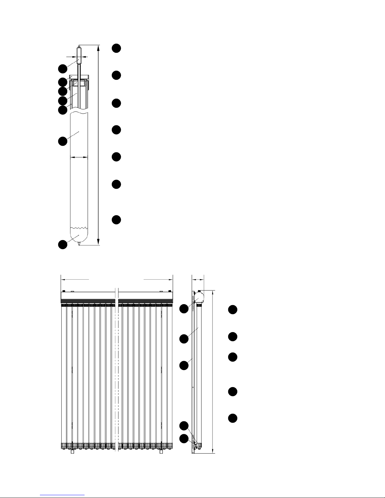
Figure 1: Warmflow Solar heat pipe tubes
Figure 2: Warmflow Solar heat pipe collectors
Heat Pipe
Rapidly and efficiently transfers the sun’s energy from within the vacuum tube
into the manifold where it is transferred into the system fluid.
Tube Securing Nut
Locates and secures the vacuum tube into the manifold ensuring a positive
engagement.
Tube Seal
Seals the inner chamber of the vacuum tube to minimise convection losses
and protect the heat pipe and transfer fin from corrosion.
Transfer Fin
Conducts the sun’s energy from the vacuum tube’s absorber surface into the
heat pipe.
Vacuum Chamber
Insulates the heat pipe and transfer fin to minimise thermal losses, similar to a
vacuum flask.
Vacuum Tube
High efficiency twin-wall glass tube with 3600 advanced Al-N/Al coated
absorber surface applied by Magnetron Sutter CVD for maximum absorption of
the sun’s rays from any angle.
Getter
Intelligent boron coating that maintains the vacuum within the vacuum
chamber by chemically absorbing any air. The getter has a mirror-like
appearance when new and becomes white when spent, indicating that the
vacuum tube needs to be replaced.
1
2
3
4
5
6
7
14
58
1945
1
2
3
4
5
6
7
1
1400 (Solar SHP20)
2100 (Solar SHP30)
154
2050
2
3
4
5
Manifold
Transfers heat from the heat
pipes to the system fluid.
Vacuum tube
See previous figure.
Support Frame
Is secured to the roof and
provides support for the
manifold and bottom rail.
Tube End Supports
Support the bottom of the
vacuum tubes.
Bottom Rail
Fixes the tube end supports.
1
2
3
4
5

6
Figure 3: Warmflow Solar dual-line pump station
Expansion Vessel
Connection
6 bar Pressure Relief Valve
Flow
from Collector
Return
to Collector
Flow
to Solar Coil
Return
from Solar Coil
Filling Point
Circulating Pump
Flow Adjuster
Flow Indicator
Pressure Gauge
Flow Temperature Gauge
Return Temperature Gauge
Bleed Point
Continuous Air Separator
Multifunction
Ball Valves
7
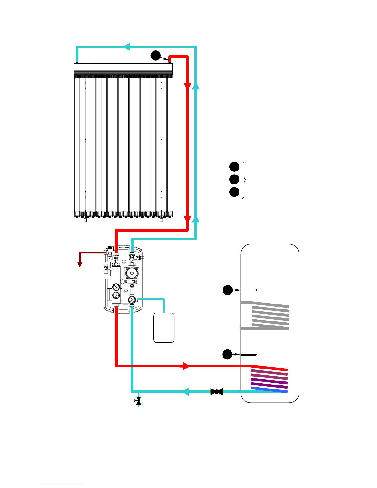
2.3 Circuit Diagrams
Figure 4: Typical domestic circuit diagram
Solar Collector
Dual
-
line
Pump Station
Pressure Relief
Discharge
Solar
Expansion Vessel
Motorised Valve
(if required)
Drain Cock
(at lowest point)
DHW
Storage Cylinder
Solar Coil
Boiler Coil
(if applicable)
T
3
T
2
T1
T1
T
2
T
3
Solar Sensors
refer to instructions for
Solar System Controller
M
FLOW
RETURN
FLOW
RETURN
8
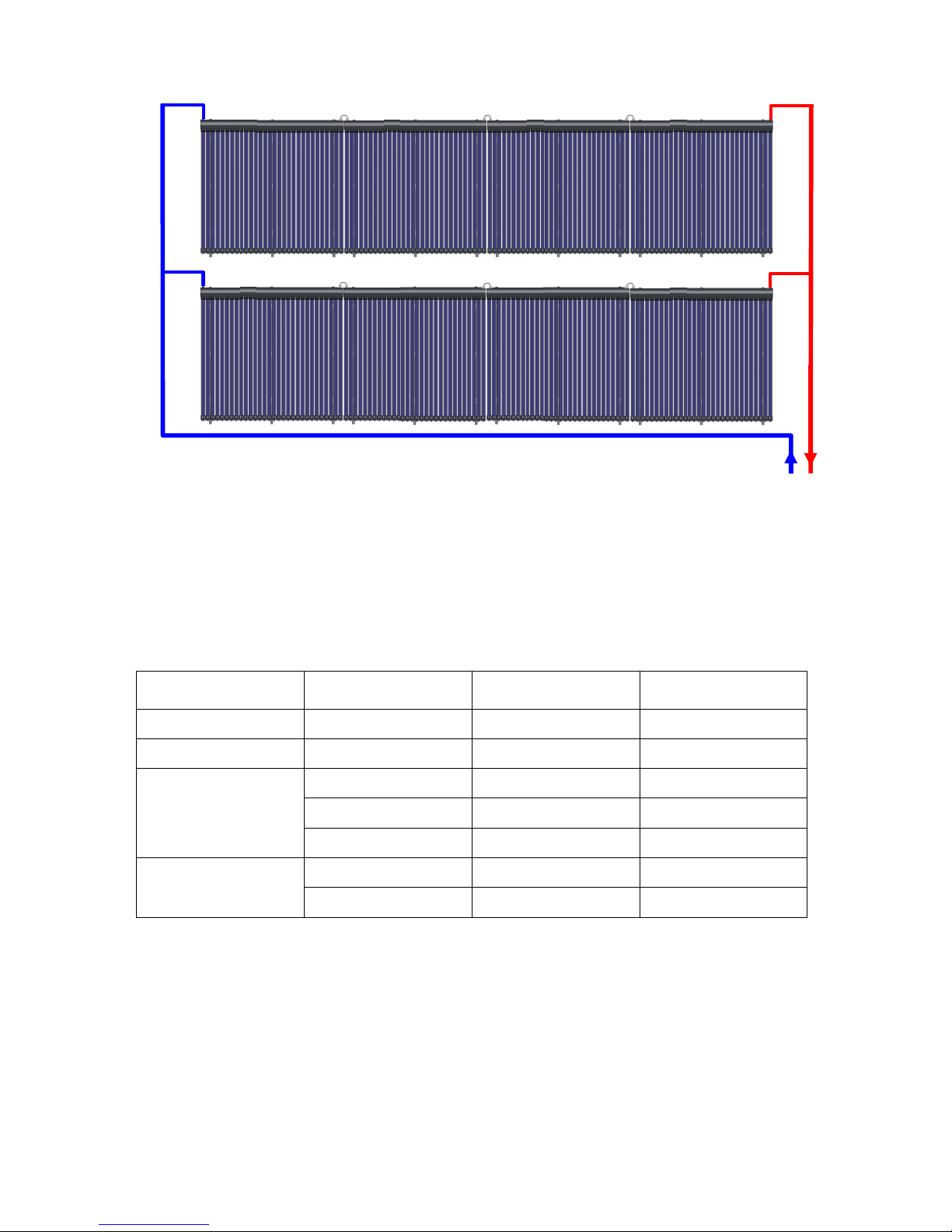
Figure 5: Circuit layout for 20m2 array (240 tubes)
2.4 Pipework and Expansion Vessel Sizing
Table 2 provides general guidance on the sizing of the system pipework and expansion
requirements. The expansion capacity is expressed as the number of Warmflow Solar
SEV18 expansion vessels required, each vessel having a volume of 18 litres.
No. of
vacuum tubes
Total length
of pipework
Minimum
pipe size
Minimum
expansion capacity
20 up to 70m 15mm 1 x SEV18
30 up to 45m 15mm 1 x SEV18
40
up to 30m 15mm 1 x SEV18
up to 40m 22mm 1 x SEV18
up to 75m 22mm 2 x SEV18
50
up to 10m 15mm 1 x SEV18
up to 45m 22mm 2 x SEV18
Table 2: Pipework and expansion vessel sizing
NOTE:
• The total length of pipework is the sum of both the flow and return runs from the cylinder
to the collector and back e.g. if the cylinder and collector were 5 metres apart, the total
length of pipework would be 10 metres (if piped directly).
• It is recommended that the minimum pipe size be used, otherwise expansion capacity
additional to that quoted may be required.
DN
32
DN
32
DN20
DN20
DN20
DN20
4 x SHP30 = 120 tubes
4 x SHP30 = 120 tubes
Note:
It is not recommended that more than
180 tubes be connected in series
 Loading...