

Page 1

System Manual
Incorporating: Installation Instructions
Commissioning Instructions
Maintenance Instructions
Guarantee Registration
Solar Thermal Systems
European Solar Keymark Approved
Products covered by this manual:
Solar SHP20 SHP30
Heat pipe vacuum tube collectors and accessories
LEAVE THIS MANUAL WITH THE END USER
Q12-027 rev 02 May ‘10
Page 2

Page 3

1
CONTENTS
1 General Information ..................................................................................................... 2
1.1 Warnings ..................................................................................................................... 2
1.2 Information ................................................................................................................... 3
1.3 Product Conformity ...................................................................................................... 3
2 Technical Characteristics ............................................................................................ 4
2.1 Technical Data ............................................................................................................. 4
2.2 Key Components ......................................................................................................... 5
2.3 Circuit Diagrams .......................................................................................................... 7
2.4 Pipework and Expansion Vessel Sizing ....................................................................... 8
2.5 Collector Pressure Drop ............................................................................................... 9
3 Installation ...................................................................................................................10
3.1 General Requirements ................................................................................................10
3.2 Tiled Roof Installation .................................................................................................10
3.2.1 Assemble pitched roof brackets ........................................................................................... 10
3.2.2 Install pitched roof brackets .................................................................................................. 11
3.2.3 Install support frame and manifold ....................................................................................... 12
3.2.4 Connect manifold pipework .................................................................................................. 13
3.3 Slate Roof Installation .................................................................................................14
3.3.1 Install slate roof brackets ...................................................................................................... 14
3.3.2 Install support frame ............................................................................................................. 15
3.3.3 Connect manifold pipework .................................................................................................. 15
3.4 Dual-line Pump Station Installation .............................................................................16
3.4.1 Mount pump station .............................................................................................................. 16
3.4.2 Connect pump station pipework ........................................................................................... 16
3.5 Electrical Installation ...................................................................................................17
3.5.1 Mount controller .................................................................................................................... 17
3.5.2 Connect external wiring centre ............................................................................................. 17
3.5.3 Connect back-up heat source .............................................................................................. 18
4 Commissioning ...........................................................................................................19
4.1 System Filling & Flushing ............................................................................................19
4.1.1 Check expansion vessel pre-charge .................................................................................... 19
4.1.2 Calculate system volume ..................................................................................................... 19
4.1.3 Connect filling station ........................................................................................................... 19
4.1.4 Flush system ........................................................................................................................ 20
4.1.5 Fill system ............................................................................................................................. 20
4.2 Pressure Testing .........................................................................................................21
4.2.1 Pressurise and inspect system ............................................................................................. 21
4.2.2 Set system pressure ............................................................................................................. 21
4.3 Sensor Installation ......................................................................................................21
4.4 Heat Pipe Tube Installation .........................................................................................22
4.4.1 Insert tube into manifold ....................................................................................................... 22
4.5 Circuit Flow Commissioning ........................................................................................23
4.5.1 Set pump speed ................................................................................................................... 23
4.5.2 Set flow adjuster ................................................................................................................... 23
5 Maintenance ................................................................................................................24
5.1 Periodic System Check ...............................................................................................24
5.2 Annual Maintenance ...................................................................................................24
5.2.1 Check installation ................................................................................................................. 24
5.2.2 Check fluid health ................................................................................................................. 24
5.2.3 Check performance .............................................................................................................. 24
5.2.4 Annual service checklist ....................................................................................................... 25
6 Product Guarantee ......................................................................................................26
7 Installation Notes ........................................................................................................27
8 Guarantee Registration ...............................................................................................29
Page 4

2
1 GENERAL INFORMATION
1.1 Warnings
In order to qualify for the product guarantee the equipment MUST be correctly
commissioned as described herein and the guarantee registration section at the back of
this manual completed and returned.
Failure to commission and register the product may invalidate ALL guarantees.
This equipment must only be installed and commissioned by professionally qualified
personnel in accordance with current laws and standards and in line with the manufacturer’s
instructions. It is recommended that the system is installed by a competent installer such as
those registered under the Microgeneration Certification Scheme (MCS) in the United
Kingdom or with Sustainable Energy Ireland (SEI) in the Republic of Ireland.
The installation must comply with the requirements of:
- the Building Regulations
- current IEE Wiring Regulations or ETCI rules for electrical installations
Where no specific instructions are given, reference should be made to the relevant European
Standards.
This equipment must be used solely for the purpose for which it was designed and
manufactured – indirect heating of stored water (e.g. domestic hot water production).
Any other use is deemed improper and as such dangerous. The manufacturer accepts no
liability for damage or injury to persons or animals caused as a result of errors in the
installation and/or use of the equipment, or through non-compliance with current local and
national standards and/or the manufacturer’s instructions.
This equipment is only suitable for use in a sealed solar thermal system filled with the system
fluid supplied or specifically recommended by the manufacturer. The means of heating
domestic hot water (DHW), a swimming pool or other medium must be via a suitable heat
exchanger, for example the coil of a DHW storage cylinder.
This instruction manual forms an integral and essential part of the equipment and must be
kept in a safe place, available for future reference. This manual, along with the
commissioning and service records and proof of purchase, must be left with the end user.
It is essential that the heat pipe tubes are protected from overheating prior to installation.
NEVER leave uninstalled heat pipe tubes exposed to the sun.
Only unpack and install the heat pipe tubes after the rest of the system had been flushed,
filled and pressure tested and the system is ready to be brought into operation i.e. the DHW
storage cylinder is in use or the swimming pool has been filled.
If for any long periods there will be no heat load on the system (e.g. property unoccupied or
swimming pool emptied) the solar collector must either be covered or the heat pipe tubes
removed. If installing the collector onto a new-build property, DO NOT install the tubes until
the property is, or is about to become, occupied.
Due to the high temperatures that may be generated by a solar installation it is
recommended that a mixing valve be fitted to the hot water outlet from a domestic hot water
storage cylinder in order to limit the domestic hot water temperature. A setting of 60ºC is
recommended.
Page 5

3
1.2 Information
Suitable personal protective equipment (e.g. hand and eye protection) must be used when
handling glass tubes. Avoid scratching or knocking the tubes and take care to protect the
teat at the base of the tube.
After removing the packaging, check that the equipment has not been damaged. In case of
doubt, do not attempt to install the equipment. Contact the supplier immediately to report the
damage. Packaging materials must not be left within reach of children as these items may
constitute a hazard and should be disposed of responsibly.
In case of a fault and/or malfunction in the equipment, shut the system down and isolate the
electrical supply. Contact your installer for advice.
In order to maintain the efficient and safe operation of this equipment it must be serviced
annually by professionally trained personnel in line with the manufacturer’s instructions.
The equipment can be regarded as electrically safe when connected to an effective earthing
system installed in accordance with the requirements of current regulations. This
fundamental safety requirement must be checked and verified. In case of doubt, have the
electrical installation checked by a qualified electrician. The manufacturer accepts no liability
of damage or injury caused as a result of inadequate or ineffective earthing.
1.3 Product Conformity
The manufacturer declares that this equipment is manufactured to a high specification and in
compliance with the relevant standards. All Warmflow solar products are CE certified and
possess technical characteristics that comply with the following directives and standards:
- Low Voltage Directive 73/23 CEE
- Electromagnetic Compatibility Directive 89/336 CEE
- BS EN 12975 - Thermal solar systems and components – Solar collectors
Warmflow accepts no liability for the consequences of non-observance of the
instructions herein or where actions not specifically described are undertaken.
Page 6
4
2 TECHNICAL CHARACTERISTICS
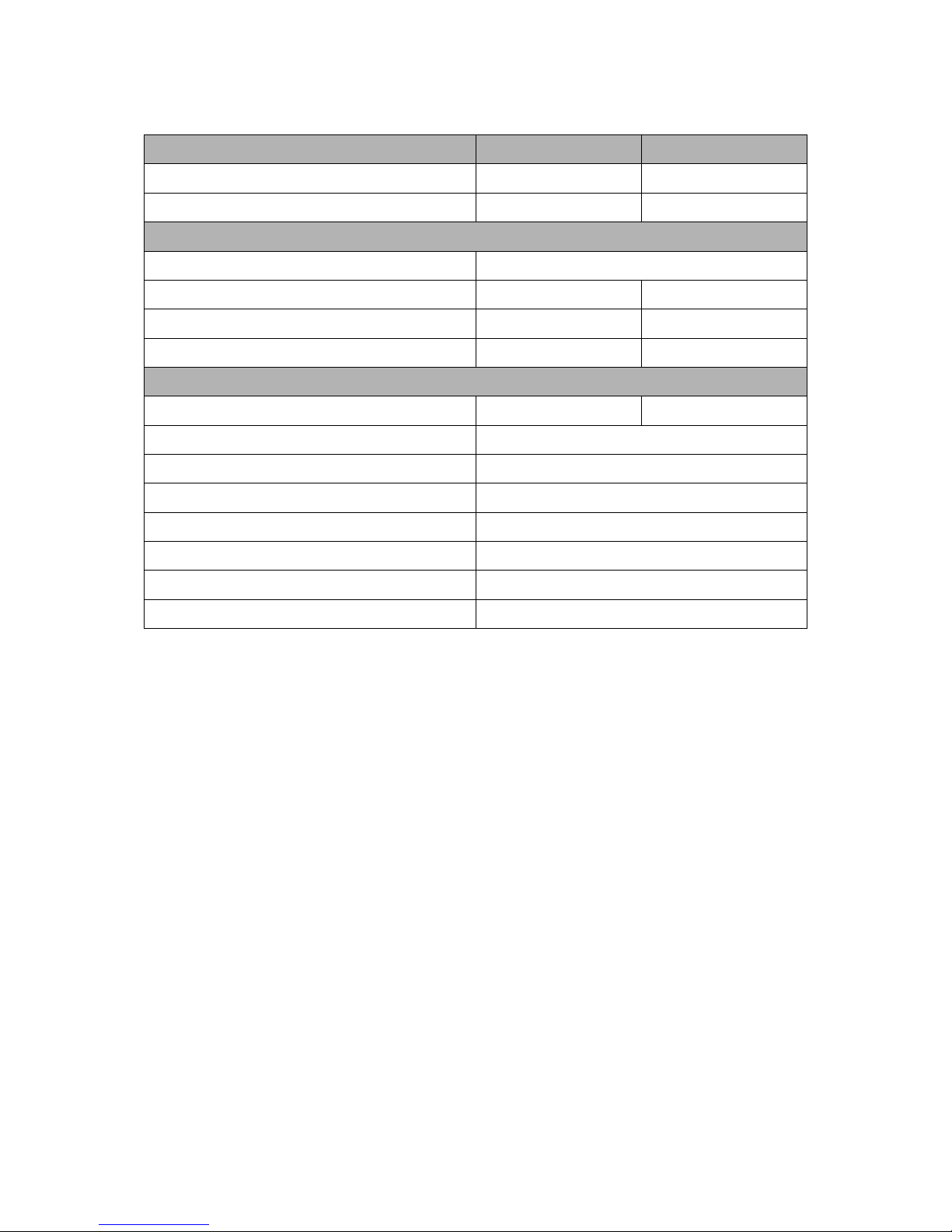
2.1 Technical Data
Model
Solar SHP20
Solar
SHP30
Absorber area (m2) (approx) 1.622 2.432
Aperture area (m2) (approx) 1.891 2.834
Fixed Parameter
Hydraulic connections G ¾” male
Gross size L x W x H (mm) 2050 x 1400 x 154 2050 x 2100 x 154
Weight empty (kg) 66.5 95.0
Fluid volume (litres) 1.2 1.7
Operating data
Rated flow rate per collector (litres/min) 2.0 3.0
Max. flow rate per collector (litres/min) 20
Max. operating pressure (bar) 6.0
Test pressure (bar) 9.0
Heat transfer fluid Warmflow Solar Fluid (water-glycol mix)
Max. working temperature (0C) 250
Permissible wind load (m/s) 25
Permissible snow load (mm) 500
Table 1: Technical data for Warmflow Solar heat pipe collectors
Page 7
5
2.2 Key Components
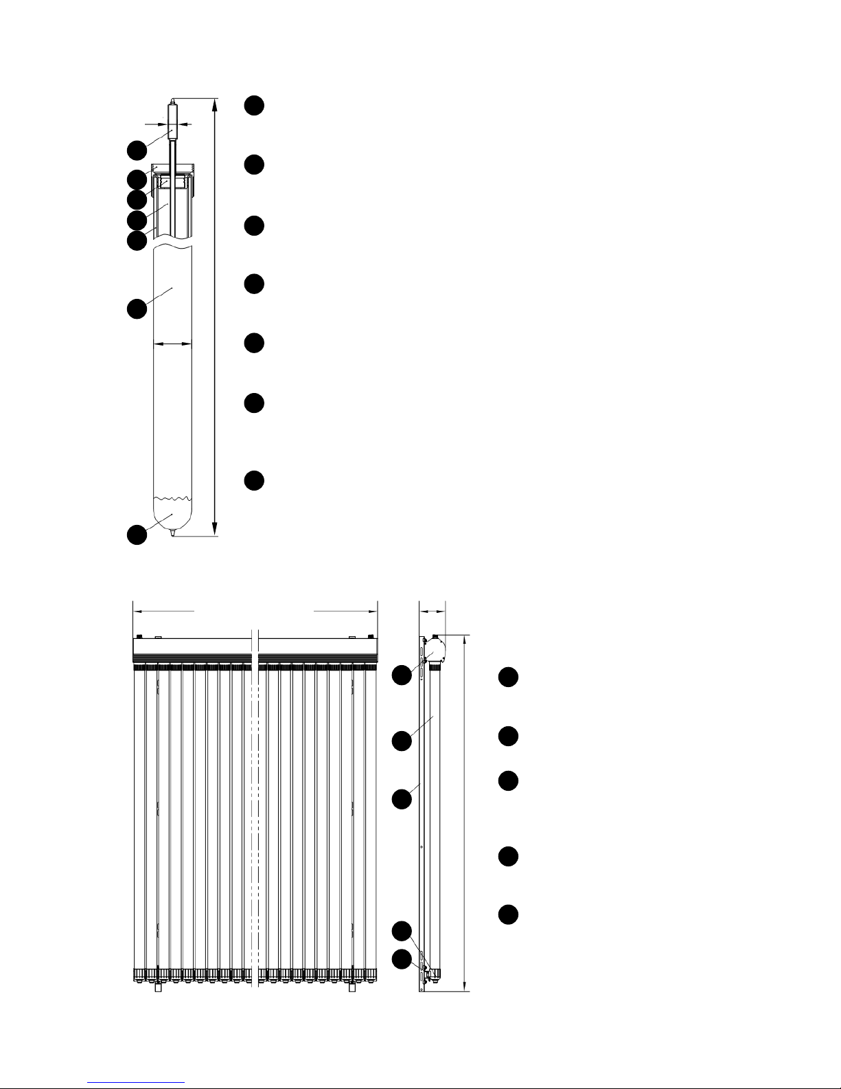
Figure 1: Warmflow Solar heat pipe tubes
Figure 2: Warmflow Solar heat pipe collectors
Heat Pipe
Rapidly and efficiently transfers the sun’s energy from within the vacuum tube
into the manifold where it is transferred into the system fluid.
Tube Securing Nut
Locates and secures the vacuum tube into the manifold ensuring a positive
engagement.
Tube Seal
Seals the inner chamber of the vacuum tube to minimise convection losses
and protect the heat pipe and transfer fin from corrosion.
Transfer Fin
Conducts the sun’s energy from the vacuum tube’s absorber surface into the
heat pipe.
Vacuum Chamber
Insulates the heat pipe and transfer fin to minimise thermal losses, similar to a
vacuum flask.
Vacuum Tube
High efficiency twin-wall glass tube with 3600 advanced Al-N/Al coated
absorber surface applied by Magnetron Sutter CVD for maximum absorption of
the sun’s rays from any angle.
Getter
Intelligent boron coating that maintains the vacuum within the vacuum
chamber by chemically absorbing any air. The getter has a mirror-like
appearance when new and becomes white when spent, indicating that the
vacuum tube needs to be replaced.
1
2
3
4
5
6
7
14
58
1945
1
2
3
4
5
6
7
1
1400 (Solar SHP20)
2100 (Solar SHP30)
154
2050
2
3
4
5
Manifold
Transfers heat from the heat
pipes to the system fluid.
Vacuum tube
See previous figure.
Support Frame
Is secured to the roof and
provides support for the
manifold and bottom rail.
Tube End Supports
Support the bottom of the
vacuum tubes.
Bottom Rail
Fixes the tube end supports.
1
2
3
4
5
Page 8

6
Figure 3: Warmflow Solar dual-line pump station
Expansion Vessel
Connection
6 bar Pressure Relief Valve
Flow
from Collector
Return
to Collector
Flow
to Solar Coil
Return
from Solar Coil
Filling Point
Circulating Pump
Flow Adjuster
Flow Indicator
Pressure Gauge
Flow Temperature Gauge
Return Temperature Gauge
Bleed Point
Continuous Air Separator
Multifunction
Ball Valves
Page 9
7
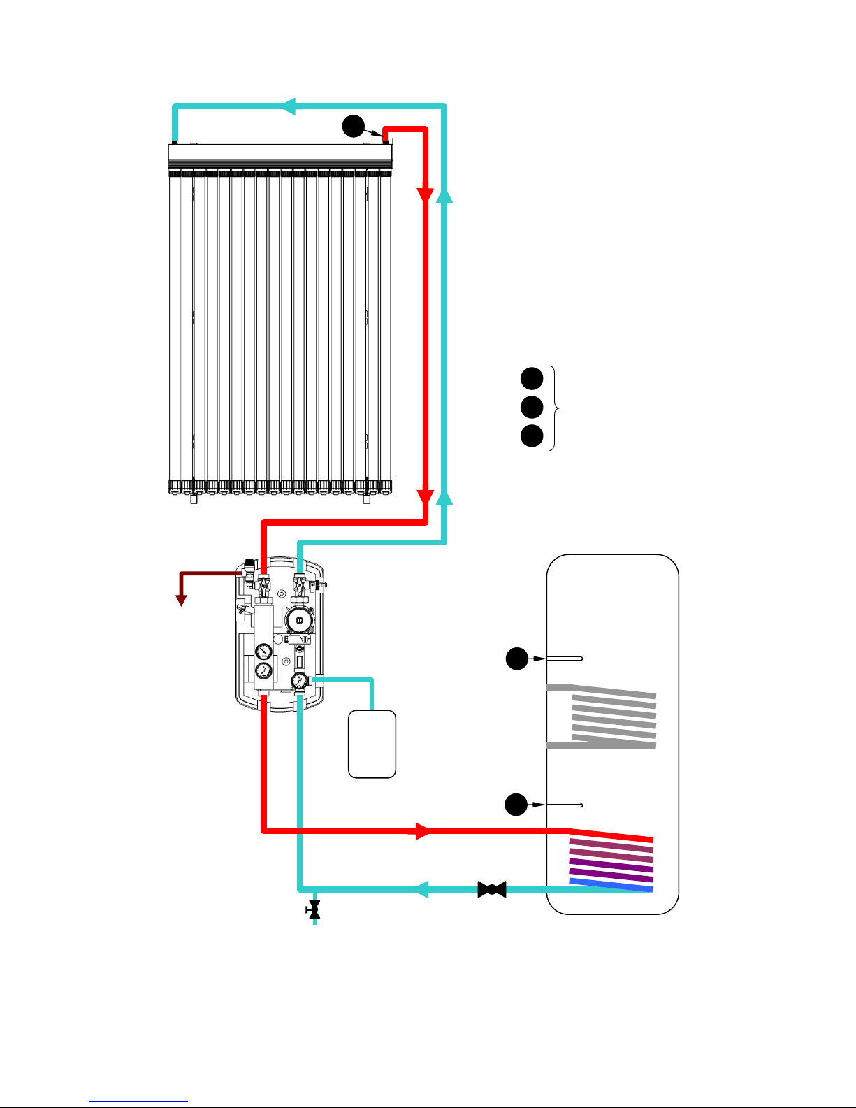
2.3 Circuit Diagrams
Figure 4: Typical domestic circuit diagram
Solar Collector
Dual
-
line
Pump Station
Pressure Relief
Discharge
Solar
Expansion Vessel
Motorised Valve
(if required)
Drain Cock
(at lowest point)
DHW
Storage Cylinder
Solar Coil
Boiler Coil
(if applicable)
T
3
T
2
T1
T1
T
2
T
3
Solar Sensors
refer to instructions for
Solar System Controller
M
FLOW
RETURN
FLOW
RETURN
Page 10
8
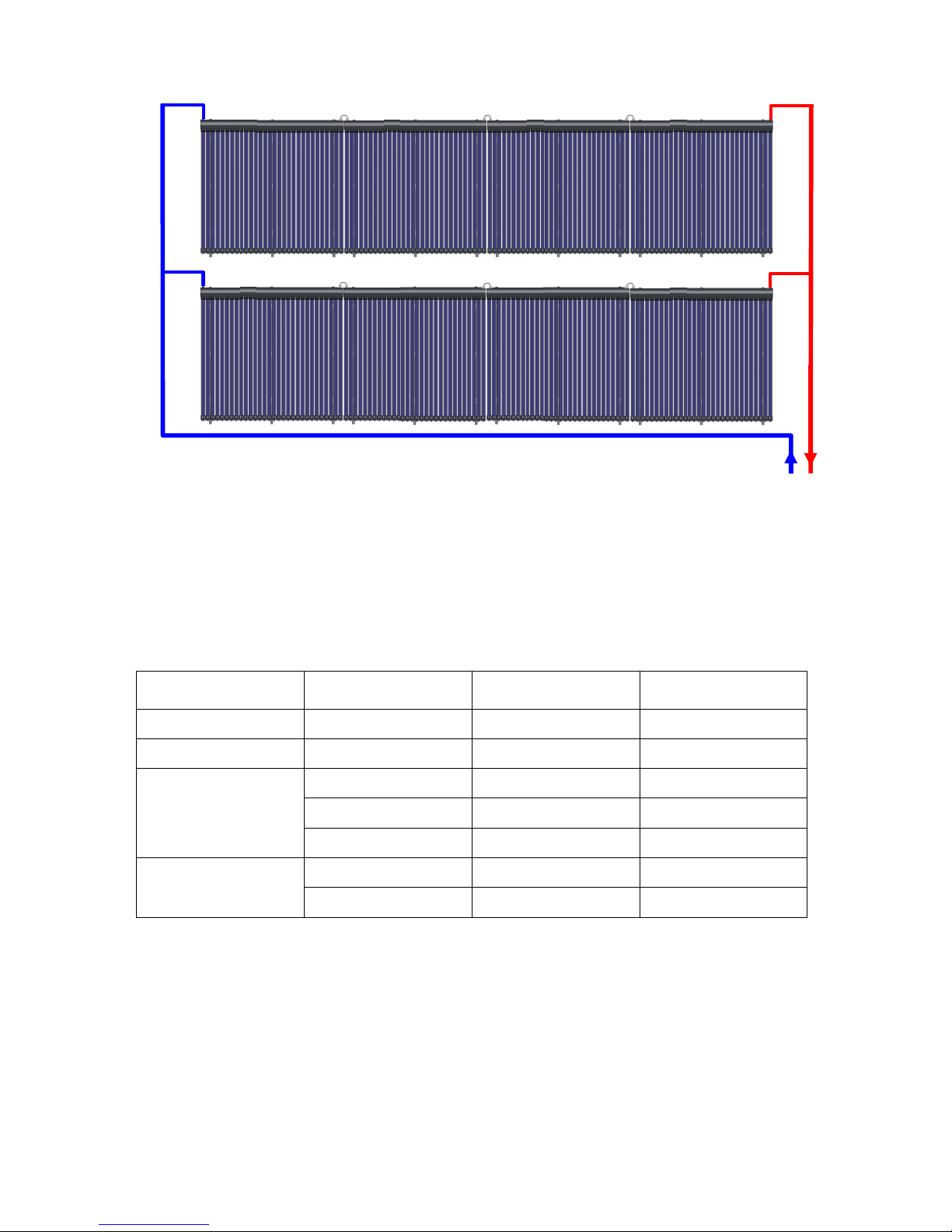
Figure 5: Circuit layout for 20m2 array (240 tubes)
2.4 Pipework and Expansion Vessel Sizing
Table 2 provides general guidance on the sizing of the system pipework and expansion
requirements. The expansion capacity is expressed as the number of Warmflow Solar
SEV18 expansion vessels required, each vessel having a volume of 18 litres.
No. of
vacuum tubes
Total length
of pipework
Minimum
pipe size
Minimum
expansion capacity
20 up to 70m 15mm 1 x SEV18
30 up to 45m 15mm 1 x SEV18
40
up to 30m 15mm 1 x SEV18
up to 40m 22mm 1 x SEV18
up to 75m 22mm 2 x SEV18
50
up to 10m 15mm 1 x SEV18
up to 45m 22mm 2 x SEV18
Table 2: Pipework and expansion vessel sizing
NOTE:
• The total length of pipework is the sum of both the flow and return runs from the cylinder
to the collector and back e.g. if the cylinder and collector were 5 metres apart, the total
length of pipework would be 10 metres (if piped directly).
• It is recommended that the minimum pipe size be used, otherwise expansion capacity
additional to that quoted may be required.
DN
32
DN
32
DN20
DN20
DN20
DN20
4 x SHP30 = 120 tubes
4 x SHP30 = 120 tubes
Note:
It is not recommended that more than
180 tubes be connected in series
Page 11
9
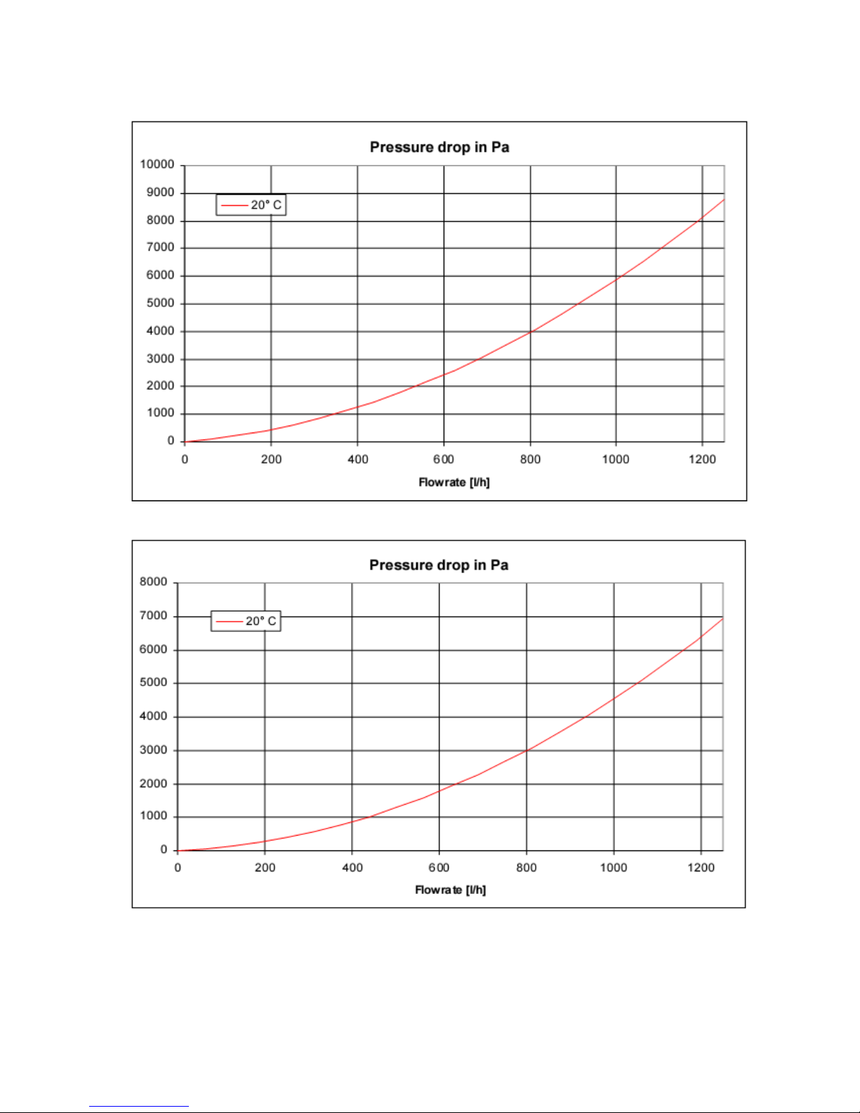
2.5 Collector Pressure Drop
Figure 6: SHP20 collector pressure drop
Figure 7: SHP30 collector pressure drop
Page 12
10
3 INSTALLATION
3.1 General Requirements
Select a suitable position for the collector. Ensure the section of roof to which the collector is
being installed is capable of supporting its weight and any likely wind loads.
The collector should face as close as practicably possible towards south and not be shaded
by surrounding buildings, trees or other sections of the building to which it is being installed.
The collector must be installed with the manifold at the top (not on its side) and on a section
of roof with a tilt of between 250 and 600 to the horizontal. Table 3 shows the effect of the
tilt and orientation of the collector on performance.
Tilt of
collector
Orientation of collector
South
South
-
east
South-west
East / West
North
-
east
North-west
North
300
Recommended 4.3% loss 15% loss 27% loss 32% loss
450
1.8% loss 7.1% loss 20% loss 36% loss 40% loss
600
7.8% loss 14% loss 28% loss 44% loss 53% loss
Data derived from SAP2005
Table 3: Loss of performance due to collector angle and orientation
The collector can be installed in 2 ways:
• tiled roof installation (refer to Section 3.2)
• slate roof installation (refer to Section 3.3)
3.2 Tiled Roof Installation
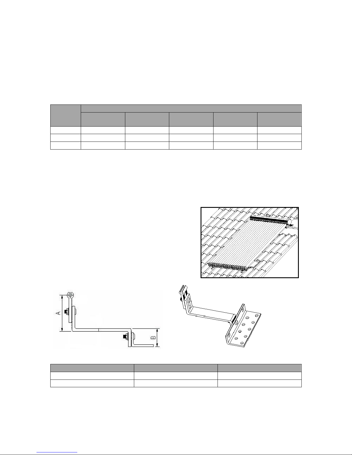
3.2.1 Assemble pitched roof brackets
Adjust the settings of the solar pitched roof brackets
(SPRB~) by varying the dimensions A and B to suit
the shape and thickness of the tiles. The dimensions
can be varied within the limits specified. Bolt the 3
sections of the brackets firmly together using the
fasteners supplied.
Figure 8: Adjustment of pitched roof bracket
Dimension
Minimum
Maximum
A 70 140
B 45 60
Table 4: Adjustment limits for pitched roof brackets
Page 13
11
3.2.2 Install pitched roof brackets
Remove as many tiles as necessary to gain access to the rafters and laths and to determine
their location and spacing. It may be helpful to position the collector nearer the ridgeline and
work down from the top, removing the ridge tiles first.
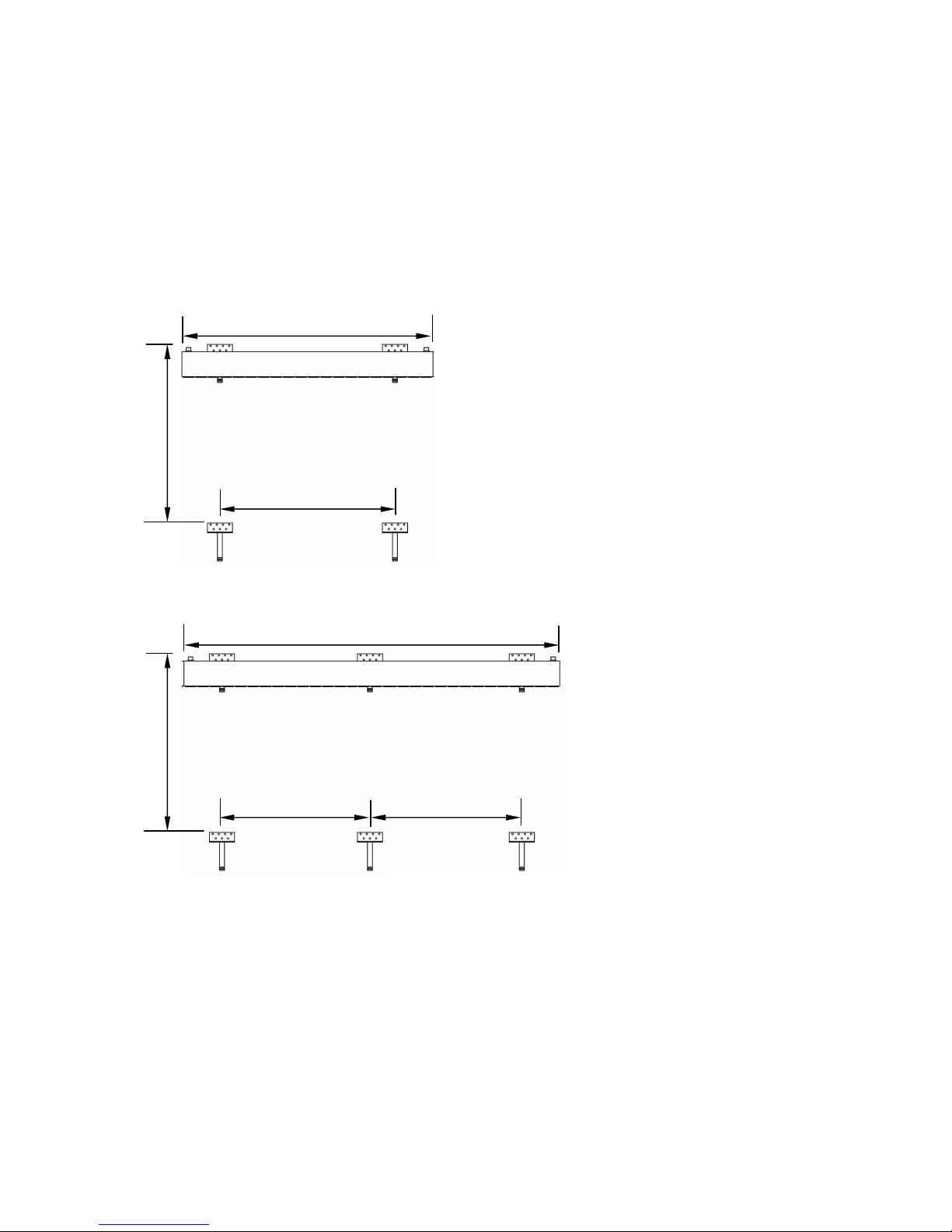
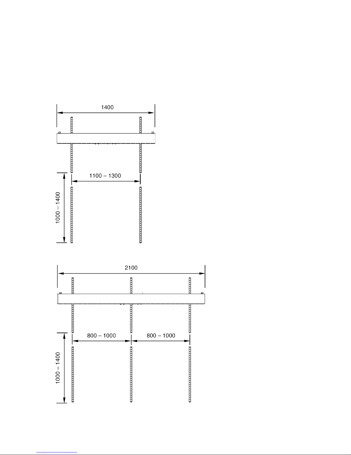
Using suitable fasteners (not supplied) fix the pitched roof brackets to the most convenient
rafters ensuring the bracket spacing is within the guidelines below. As much as is possible,
space each set of brackets equally either side of each collector centreline.
In some instances, depending on the tile design, it may be necessary to notch the underside
of the overlapping tile to allow it to sit flush. If necessary the tiles can be cut and the roof
made watertight using suitable lead flashing (not supplied).
Figure 9: Pitched roof bracket layout for SHP20 collector
Figure 10: Pitched roof bracket layout for SHP30 collector
2100
800 – 1000
800 – 1000
1413 – 1705
SHPM30 Manifold
1400
1100 – 1300
1413 – 1705
SHPM20 Manifold
Page 14
12
3.2.3 Install support frame and manifold
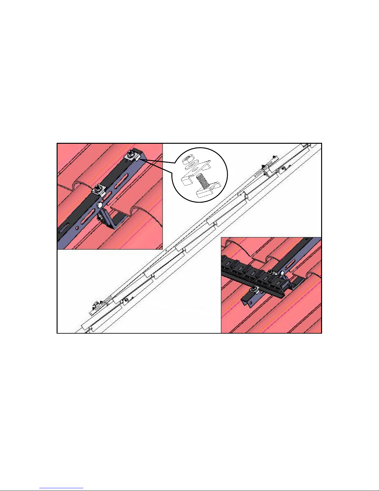
Fit the clamps supplied with the heat pipe manifold (SHPM~) to each rail of the support frame
(SSF~), placing a pair at the top and at the bottom of each rail as shown.
Install the support frame fixing each rail to the pitched roof brackets by passing the fasteners
supplied through the sides of the rail and the loop on the end of each pitched roof bracket.
Ensure the pair of clamps that are further apart are at the top, as these will secure the
manifold. The clamps closer together go at the bottom and secure the bottom rail.
Fit the bottom rail supplied with the manifold to the lower end of the support frame and
secure in place by tightening the clamps. Ensure the clamps either side of the bottom rail
face inwards towards it and that the edges of the clamps securely grip the lip on the rail.
Fit the manifold to the upper end of the support frame in a similar fashion, again ensuring the
clamps either side of the manifold face inwards towards it and that the edges of the clamps
securely grip the lip on the manifold.
Figure 11: Support frame and manifold installation
WARNING: Only unpack and install the heat pipe tubes after the rest of the system has been
flushed, filled and pressure tested and the system is ready to be brought into operation i.e.
just prior to commissioning, in order to prevent damage from excessive heat build-up.
Page 15
13
3.2.4 Connect manifold pipework
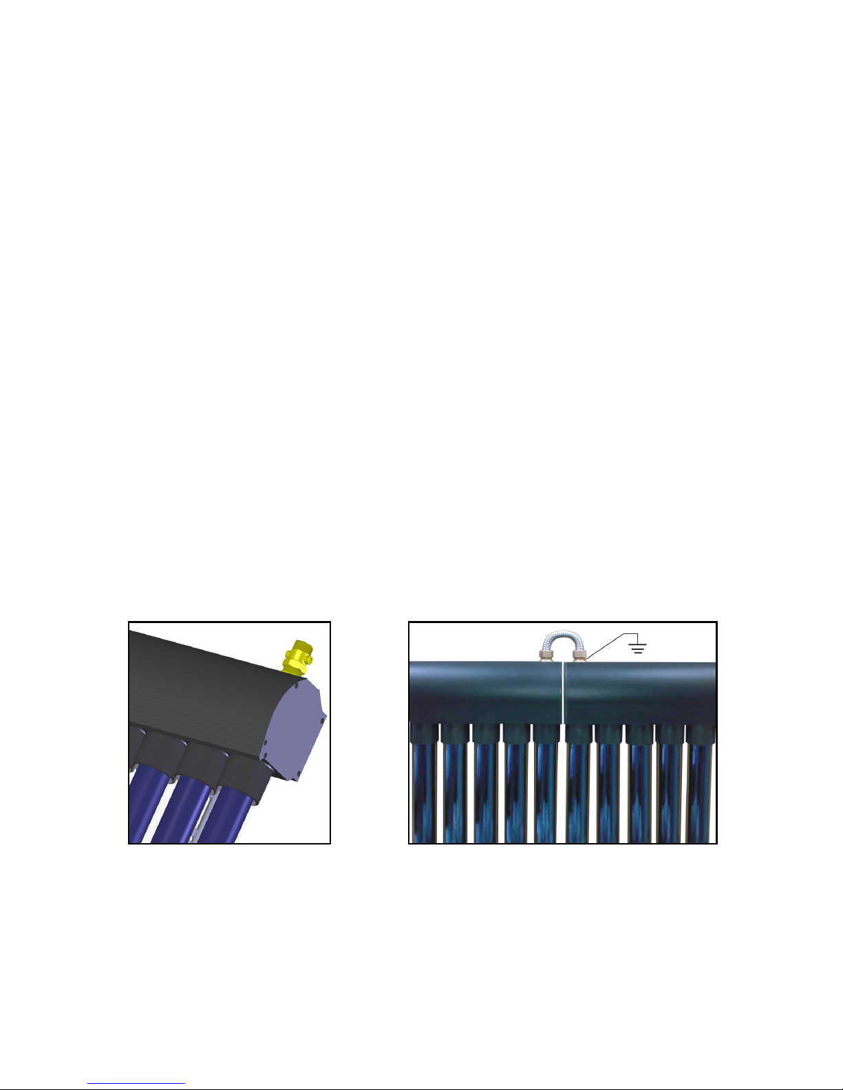
To the flow (outlet) from the heat pipe manifold, fit the temperature sensor pocket supplied,
sealing the connection with PTFE tape (not supplied) and setting the pocket to a suitable
angle to allow the sensor cable to be secured to the flexible pipework. Either end of the
manifold can be used for the flow (whichever is most convenient) but the sensor pocket must
be fitted on the flow (outlet) side.
Liberally apply the heat conducting paste, supplied with the manifold (SHP~), to the PT1000
temperature sensor with the black cable, supplied with the system controller (SSC~), then
insert the sensor into the sensor pocket. Ensure the sensor is fully inserted in the pocket.
Once the pipework has been insulated, secure the cable to the outside of the insulation using
an appropriate cable tie to prevent the sensor from coming out of the pocket.
If installing multiple collectors, connect each pair using the manifold connector (SMC~) and
sealing washers supplied with the extension kit (Solar SHPX~).
Provide effective lightening protection by connecting a suitable conductor to either the flow or
return connection of EACH collector installed.
Connect the pre-insulated flexible hoses (SFH~) to the return connection of the manifold and
to the sensor pocket on the flow connection using the washers provided. Route the pipes
through appropriate flashing and into the roof space. The flashing should seal directly onto
the pipes, rather than onto the insulation, as the insulation could absorb water over time and
lead to water ingress to the property.
Use appropriate fittings and sealing (not supplied) to either extend the hoses or connect to
rigid pipework then plumb the flow and return pipework to the top connections of the dual-line
pump station (SDPS~).
ALL pipework must be fully insulated with high temperature insulation (such as Armacell
HT/Armaflex).
Solder ring fittings and standard solder joints must not be used, as the high temperatures
generated occasionally can melt the solder. Use only compression fittings, appropriate union
fittings or high temperature solder or braze suitable for up to 2500C.
Figure 12: Sensor pocket location
Figure 13: Connecting multiple collectors
Page 16
14
3.3 Slate Roof Installation
Slate roof installation is essentially the same as tiled roof installation, only that the pitched
roof brackets (SPRB~) may not be suitable. Slate roof brackets are available, codes
SSRB20 and SSRB30 (for 20-tube and 30-tube manifold installations respectively).
3.3.1 Install slate roof brackets
Using suitable fasteners (not supplied) fix the brackets to the most convenient rafters
ensuring the bracket spacing is within the guidelines below. As much as is possible, space
each set of brackets equally either side of each collector centreline.
Figure 14: Bracket layout for SHP30 collector
Figure 15: Bracket layout for SHP30 collector
SHPM30 Manifold
SHPM20 Manifold
Page 17

15
3.3.2 Install support frame
Install the support frame as described in Section 3.2.3 bolting the brackets to the underside
of the support frame rails using the same bolts that secure the manifold and bottom rail to the
rails.
3.3.3 Connect manifold pipework
Connect the manifold pipework as described in Section 3.2.4.
Page 18
16
3.4 Dual-line Pump Station Installation
3.4.1 Mount pump station
Route the supply cable (not supplied) behind the dual-line pump station (SDPS~) and
through the hole in the centre of the rear casing.
Using the fasteners supplied (if suitable, otherwise use appropriate alternatives) mount the
pump station on a flat vertical surface. It must not be mounted horizontally or at an angle.
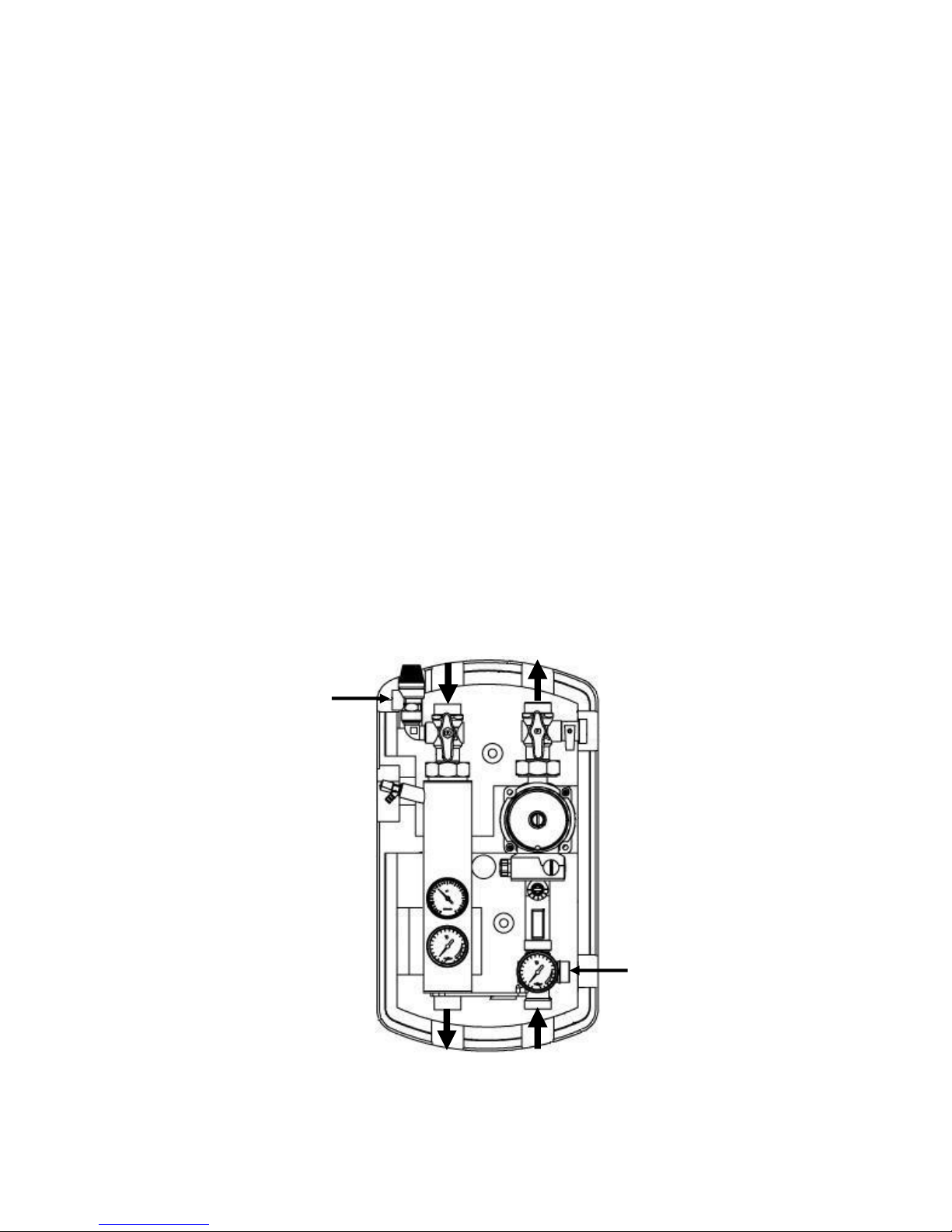
3.4.2 Connect pump station pipework
Fit the 1” x 22mm connection tails (supplied) to the four pipework connections A, B, C & D of
the pump station using the sealing washers provided. Tighten firmly but do not over-tighten.
Alternatively, suitable flexible pipework with appropriate 1” union nuts and washers can be
used to connect the pump station.
Connect the pipework running from the collector to top connections A & B of the pump
station as indicated. The pipe connected to A must be the flow from the collector i.e. the end
of the collector with fitted with the temperature sensor pocket.
Connect the pipework running from the solar coil of the DHW storage cylinder (or swimming
pool heat exchanger) to the bottom connections C & D of the pump station as indicated.
Pipe the pressure relief discharge E to a safe visible discharge point.
Connect the solar expansion vessel (SEV~) to the expansion vessel connection F via the
flexible hose, using the sealing washers supplied with the vessel fitting kit (SVFK~). Mount
the vessel as instructed in the fitting kit instructions.
Note: Solder ring fittings and standard solder joints must not be used, as the high
temperatures generated occasionally can melt the solder. Use only compression fittings,
appropriate union fittings or high temperature solder or braze suitable for up to 2500C.
Figure 16: Dual-line pump station installation
Expansion Vessel Connection
(F)
Pressure Relief Discharge
(E)
Flow from
Collector
(A)
Return to
Collector
(B)
Flow to
Solar Coil
(C)
Return from
Solar Coil
(D)
Page 19
17
3.5 Electrical Installation
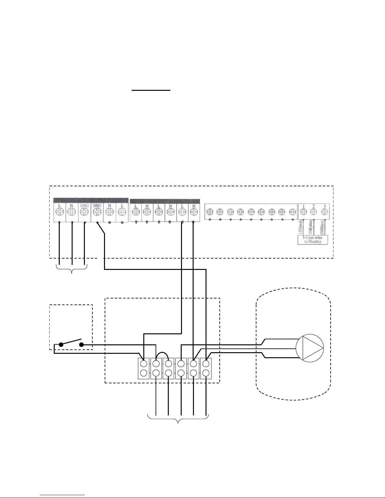
If connecting to an unvented cylinder, the pump station MUST be connected via an external
wiring centre and an energy cut-out devise MUST be installed in order to comply with the
Building Regulations. This MUST take the form of a 2-port motorised valve (not supplied)
wired through a manually-reset high limit thermostat (not supplied). If in doubt, consult the
cylinder manufacturer.
Only if connecting to an open-vented cylinder can the pump station be connected directly
to the system controller as described in the controller instruction booklet.
3.5.1 Mount controller
Install the solar system controller (SSC~) in an appropriate location as described in the
instructions supplied. Connect the wiring centre and user interface as instructed. Connect a
permanent live supply to the wiring centre, via a fused spur isolator.
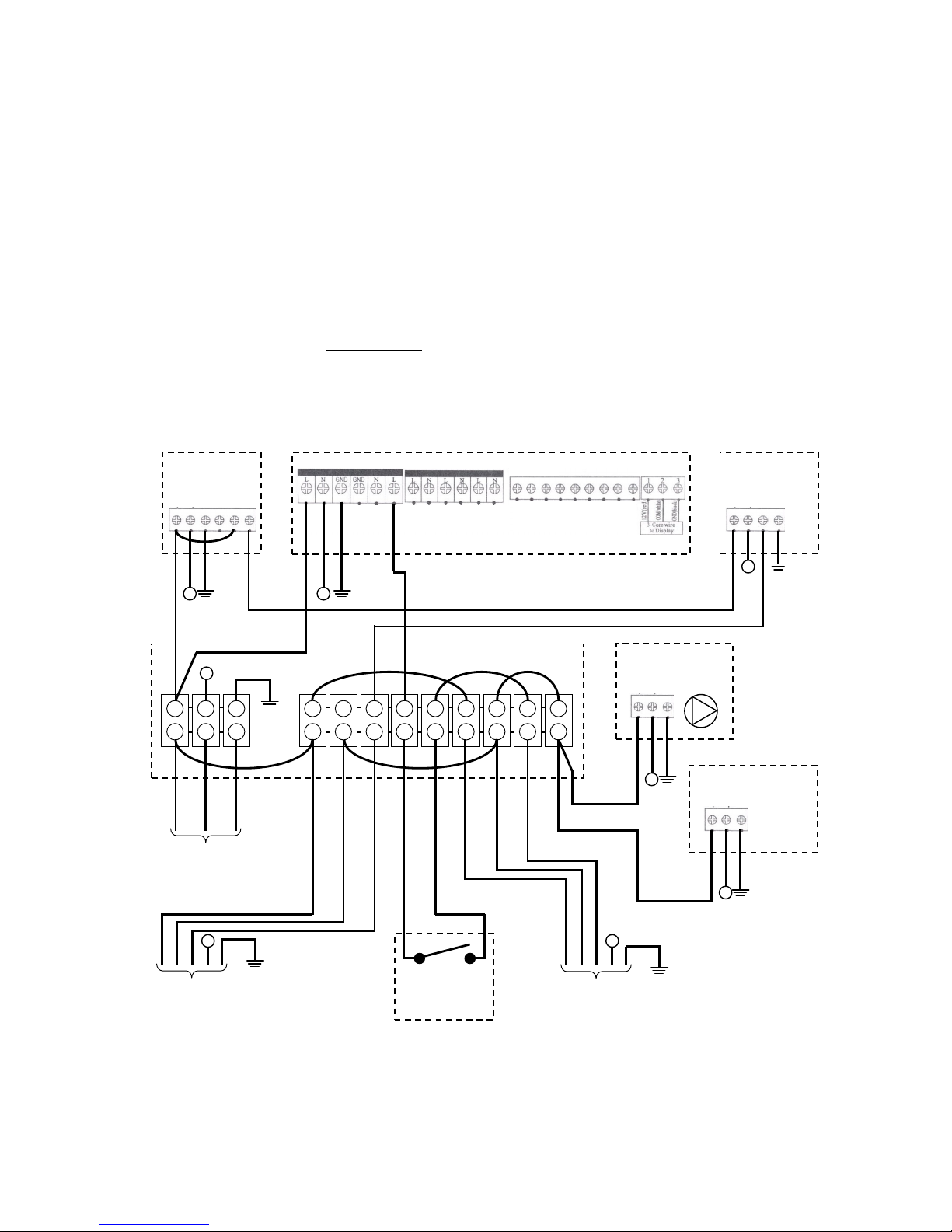
3.5.2 Connect external wiring centre
Specify an appropriate 5-wire motorised valve (not supplied) and connect it as shown.
Connect the high limit thermostat of the solar cylinder to the wiring centre, so that power to
the motorised valve would be interrupted should the high limit thermostat trip. Wire the pump
inside the pump station as shown.
Figure 17: Wiring layout with external wiring centre
Brown
Blue
Green/Yellow
Green/Yellow
Brown
Blue
Green/Yellow
Brown
Blue
Brown Blue Green/Yellow
Brown Grey Blue Green/Yellow Orange
Dual
-
line Pump
Station (SDPS~)
Pump
External Wiring Centre
(not supplied)
SSC~ Control Unit
P1
Perman
ent
Mains Supply
(via fused spur)
Cylinder
High Limit
Thermostat
(not supplied)
Motorised Valve
(on pipework to solar coil)
Diagram supplied for guidance only.
Detailed instructions on how to wire the high limit
thermostat of the solar cylinder should be sought
from the cylinder manufacturer’s instructions, as
differences may exist between products.
Page 20
18
3.5.3 Connect back-up heat source
The controller is equipped with a 3-period, 24-hour programmer with temperature control to
control the back-up heat source, such as a boiler or immersion heater(s). The back-up heat
source is powered / controlled via the H1 outputs of the control unit.
Note: The maximum operating current on the H1 contacts is 5A. If immersion heaters are
used they MUST be powered via an external relay. Powering an immersion heater directly
will overload the control unit. Failure due to overloading is not covered by the guarantee.
If connecting to an unvented cylinder, the back-up heat source MUST be connected via an
external wiring centre and an energy cut-out devise MUST be installed in order to comply
with the Building Regulations. This MUST take the form of a 2-port motorised valve (not
supplied) wired through a manually-reset high limit thermostat (not supplied). If in doubt,
consult the cylinder manufacturer.
Only if connecting to an open-vented cylinder can the back-up heat source be connected
directly to the system controller without a motorised valve.
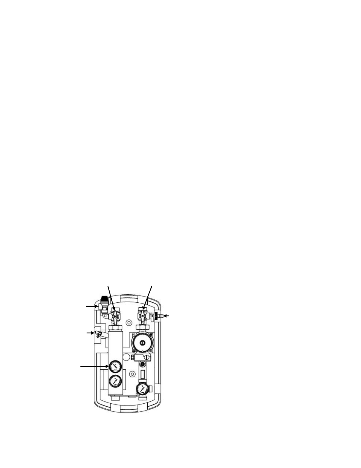
Figure 18 shows a typical single-heating-zone S-plan system with two 2-port motorised
valves. Additional heating zones can be added as required.
Figure 18: Wiring layout with external wiring centre
Grey
Orange
Brown
SSC~
Control Unit
H1
Permanent
Mains Supply
(via fused spur)
Heating
Zone Valve
Diagram supplied for guidance only.
Detailed instructions on how to wire the high limit thermostat of the solar cylinder should be sought from the cylinder
manufacturer’s instructions, as differences may exist between products.
L N E
CH OFF COM CH ON
CH Programmer
L1 N L2
CH Room Stat
E
N
External Wiring Centre
Brown
Blue
G/Y
Brown
Blue
G/Y
N N
Brown
Blue
G/Y
N
N
Cylinder
Zone Valve
(on back-up coil)
Cylinder
High Limit
Thermostat
N
Grey
Orange
Brown
Back-up Heat Source
(e.g. Boiler)
Back-up Circuit
Circulating Pump
(if applicable)
Blue
G/Y
N
Blue
G/Y
N
Brown
Brown
Page 21
19
4 COMMISSIONING
In order to qualify for the product guarantee the equipment MUST be correctly commissioned
as described herein and the guarantee registration section at the back of this manual
completed and returned.
Failure to commission and register the product may invalidate ALL guarantees.
4.1 System Filling & Flushing
System flushing, filling and pressure testing should be performed BEFORE the heat pipe
tubes are fitted to the manifold. In this way the system remains cold throughout, avoiding the
risk of burns.
4.1.1 Check expansion vessel pre-charge
PRIOR TO FILLING THE SYSTEM use a tyre pressure gauge to check the pre-charge
pressure of the expansion vessel bladder. This is measured at the Schrader valve under the
cap on the bottom of the vessel. The pressure should be 3.0 bar. If necessary, release air
by depressing the valve centre pin or top up with a foot pump.
4.1.2 Calculate system volume
Calculate the system volume referring to the cylinder manufacturer’s instructions for the
volume of the coil and to Table 1 for the volume of the collector (remembering to add all the
manifold volumes if more than one are fitted).
As a guide, the volume of the pipework will be approximately:
- 0.4 litres for every metre of 22mm pipework
- 0.2 litres for every metre of 15mm pipework
- 0.1 litres for every metre of 10mm pipework
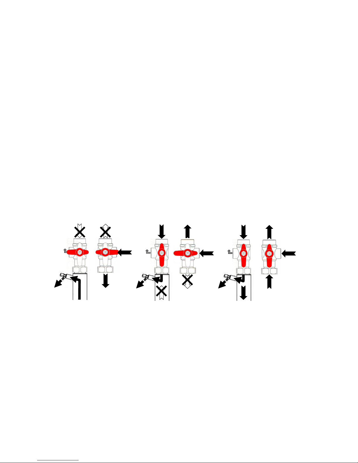
4.1.3 Connect filling station
Connect the outlet from the filling station to the filling point A of the dual-line pump station.
Pipe the outlet from the bleed point B to the filling station header tank using a suitable 8mm
ID hose. Secure the hose to the bleed point with an appropriate jubilee clip.
Figure 19: Pump station filling method
Filling Point
(A)
Multifunction
Ball Valve
(Right)
Multifunction
Ball Valve
(Left)
Pressure
Relief Valve
(D)
Bleed Point
(B)
Pressure
Gauge
(C)
Page 22
20
4.1.4 Flush system
Having calculated the total system volume, fill the header tank of the filling station with a
proprietary solar system flushing fluid (such as Sentinel R200).
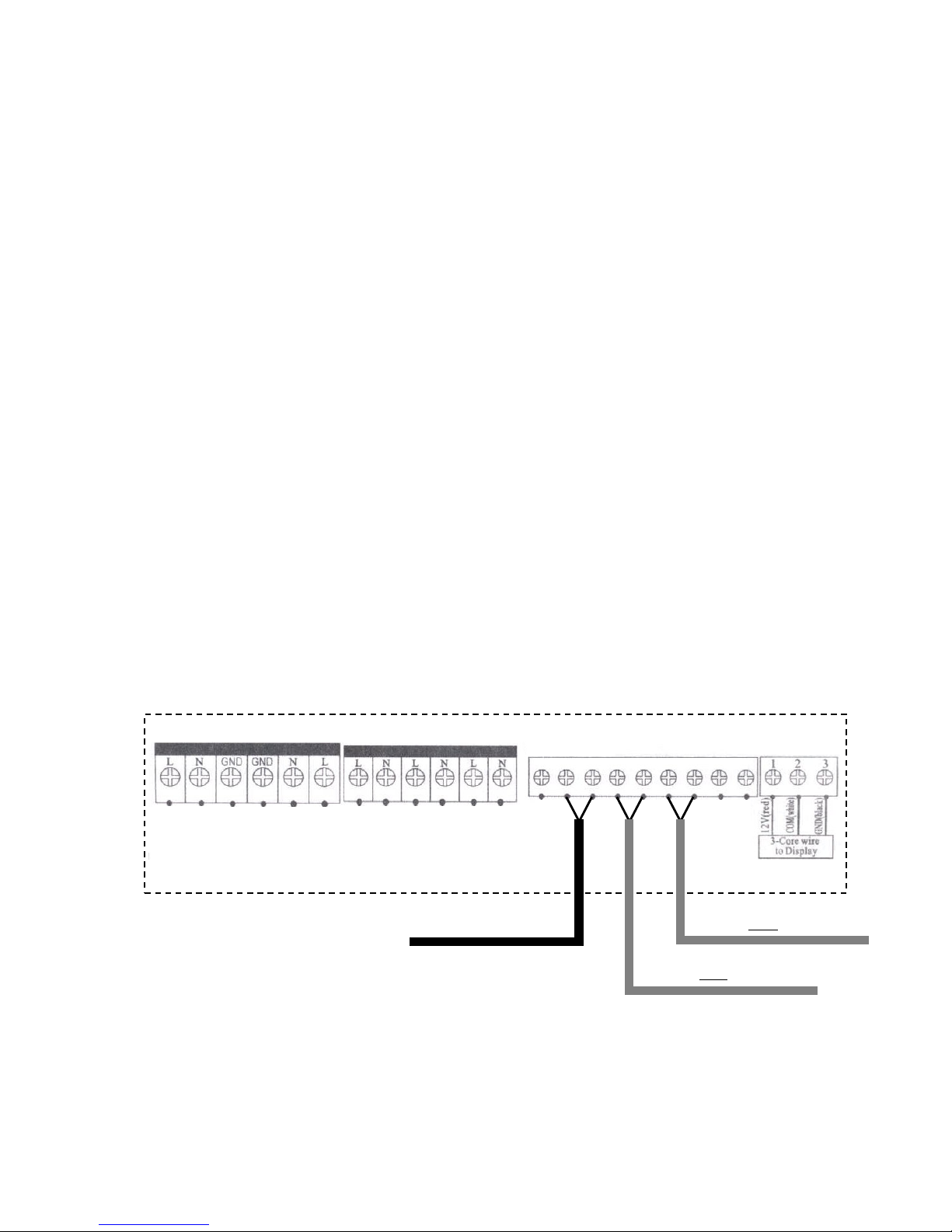
Manually open any motorised valve on the solar circuit then open the ball valve at filling point
A. Open the valve at bleed point B using a radiator key or flat head screwdriver.
Set the multifunction ball valves to Filling Position 1 as shown. Start the filling station
pump. The fluid will flow in at the filling point, down through the coil of the cylinder and out at
the bleed point, thus filling the lower section of the system. Run the filling station with the
valves in Filling Position 1 until no further air flows from the bleed point.
Adjust the multifunction ball valves to Filling Position 2 as shown, adjusting the left hand
valve first. The fluid will now flow in at the filling point, up through the collectors and out at
the bleed point, thus filling the upper section of the system. Continue to run the filling station
with the valves in Filling Position 2 until no further air flows from the bleed point.
The system is now filled with flushing fluid and ready to be flushed.
Set the multifunction ball valves to Normal Operating Position as shown. Following the
instructions supplied with the system controller, manually activate the circulating pump by
accessing the HND Menu and setting HND1 to On. Ensure that any motorised valve is
activated and that the pump on the pump station is turning. Bleed any air from the pump
using the centre bleed screw.
Run the filling station for the period recommended by the flushing fluid manufacturer (20
minutes in the case of Sentinel R200). Once complete, set HND1 to Off, stop the filling
station pump then drain all flushing fluid from the filling station and from the system. Dispose
of the flushing fluid as instructed by the fluid manufacturer.
Figure 20: Multifunction ball valve filling positions
4.1.5 Fill system
The system may ONLY be filled with Warmflow Solar Fluid, which is a specially blended
solution of propylene glycol with corrosion inhibitors designed specifically for use with solar
collectors to provide effective heat transfer, anti-freeze and corrosion protection.
Repeat the process used for flushing but this time using Warmflow Solar Fluid (SF~).
Run the filling station for at least 45 minutes (15 minutes with the valves in each filling
position) and as long as is required to eliminate all air from the system (when no more
bubbles are present in the fluid issuing from the bleed point). If there is any air noise from
the circulating pump, bleed it using the centre bleed screw – this may need to be done
several time during filling.
Once fully bled, proceed with pressure testing.
Pressure
Relief
Filling Position 1
Filling Position
2
Normal Operating
Position
Pressure
Relief
Pressure
Relief
Page 23
21
4.2 Pressure Testing
4.2.1 Pressurise and inspect system
On completion of system filling, close the valve at bleed point B. This will cause the system
pressure to rise as the filling station pump will now be dead-heading. Using the regulator on
the filling station (if fitted) set the outlet pressure to 5.5 bar (or as high as possible if 5.5 bar
cannot be achieved).
Close the filling point ball valve and stop the filling station pump. Disconnect the filling
station hoses from filling point A and bleed point B. Check that neither valve is leaking fluid
Over a period of at least 45 minutes, inspect the complete installation for evidence of
leakage from any joints or pipework and repair as necessary. Monitor the system pressure –
if a pressure drop is seen, this indicates a leak. All leaks must be located and rectified as a
loss of system pressure may lead to freezing during the winter months, causing severe
damage to the system.
4.2.2 Set system pressure
Using the pressure relief valve (so as to confirm its correct operation) reduce the system
pressure to 3.5 bar by turning the head of the valve by hand. Ensure the valve closes when
released and that the flow of fluid ceases.
4.3 Sensor Installation
Referring to the Solar System Controller instruction booklet, install and secure the sensors in
the cylinder sensor pockets and wire the control unit. The panel sensor should already have
been fitted in Step 3.2.4.
• Ensure sensor T1 (with the black cable) is fitted in the sensor pocket at the panel and
that it is wired to the T1 terminals of the control unit.
• Ensure sensor T2 (with a
grey cable) is fitted in the lower sensor pocket of the
cylinder and that it is wired to the T2 terminals of the control unit.
• Ensure sensor T3 (also with a grey cable) is fitted in the upper sensor pocket of the
cylinder panel and that it is wired to the T3 terminals of the control unit.
Figure 21: Sensor installation
If the sensors are not correctly located and wired, the system will not perform correctly and
may not operate at all.
If there is only 1 sensor pocket on the cylinder, install the T2 sensor in the pocket and do
NOT use the T3 sensor i.e. leave the T3 terminals of the control unit unwired.
T1 –
Black
Cable
to collector sensor pocket
Brown
Blue
SSC~ Control U
nit
T1 T2 T3
T2 –
Grey Cable
to cylinder lower sensor pocket
T3 – Grey Cable
(if fitted)
to cylinder upper sensor pocket
Page 24
22
4.4 Heat Pipe Tube Installation
Only unpack and install the heat pipe tubes after the rest of the system had been flushed,
filled and pressure tested and the system is ready to be brought into operation i.e. the DHW
storage cylinder is in use or the swimming pool has been filled.
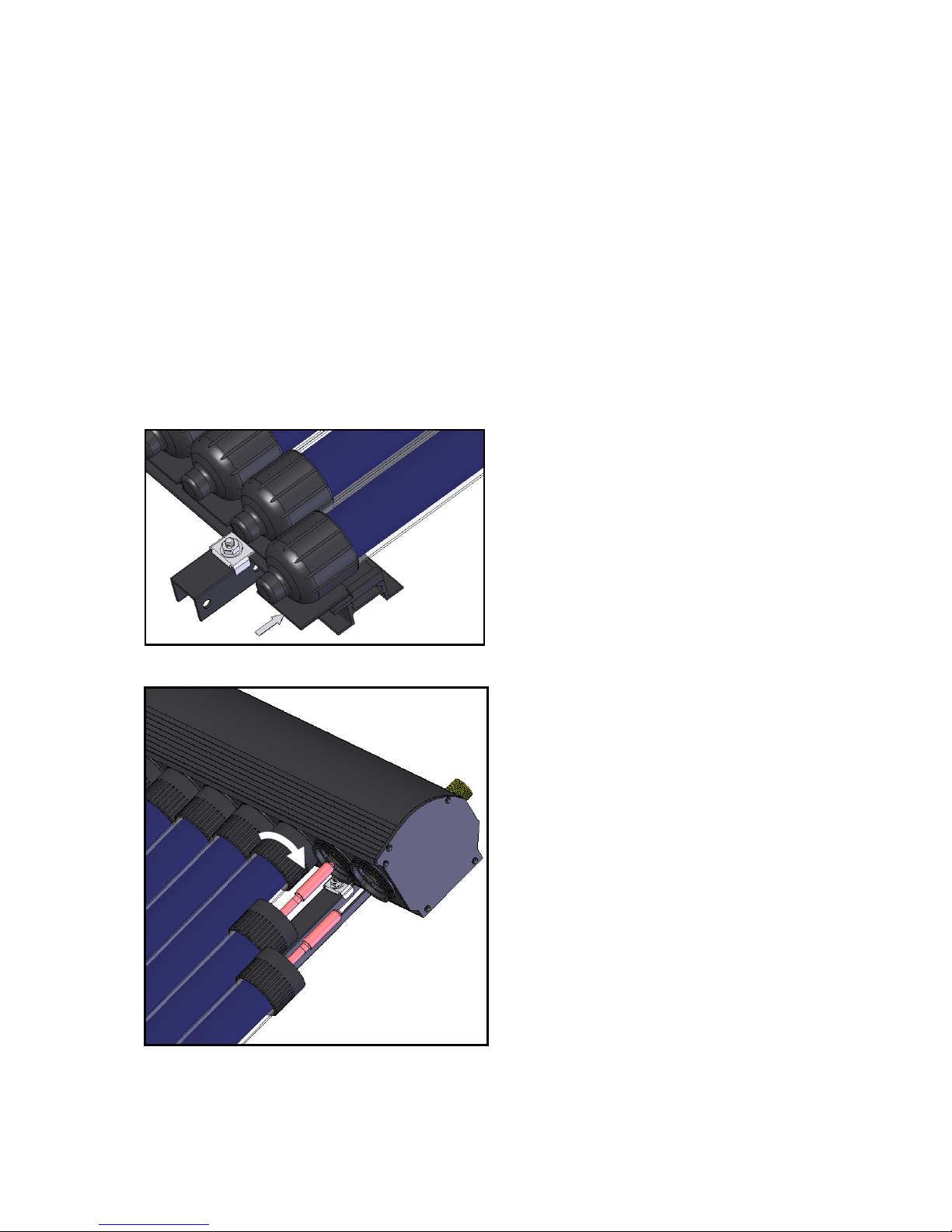
4.4.1 Insert tube into manifold
Apply a generous amount of heat conducting glue (supplied with the manifold kit) to the
exposed copper heat exchanger on the end of the heat pipe tube.
With the support frame and manifold correctly installed as per Section 3.2.3, insert the heat
exchanger end of the tube into the manifold.
Support the bottom end of the tube with your hand then slide on the tube end support,
engaging it with the guide on the bottom rail at the same time. Push the end support firmly
onto the end of the tube until it clicks into place on the bottom rail. Take care not to
damage the teat on the end of the glass tube!
Secure the tube by screwing the tube securing nut into the manifold as shown.
Repeat these steps for each tube of the collector, starting at one end and working across.
Figure 22: Tube end support installation
Figure 23: Heat pipe tube insertion to manifold
Page 25
23
4.5 Circuit Flow Commissioning
4.5.1 Set pump speed
Calculate the required flow rate based on the number of tubes. A flow rate of 1 litre per
minute is required for every 10 tubes, so:
- If you have 20 tubes, you need 2 litres per minute
- If you have 50 tubes, you need 5 litres per minute.
The maximum flow rate that can be achieved with the pump station as supplied is 8 litres per
minute (the maximum reading on the flow indicator). If a higher flow rate is required (for an
installation of more than 80 tubes) an alternative high flow indicator can be fitted. Consult
the Customer Care Centre.
Following the instructions supplied with the solar system controller (SSC~), manually activate
the circulating pump by accessing the HND Menu and setting HDN1 to On. Ensure any
motorised valve opens and the circulating pump starts.
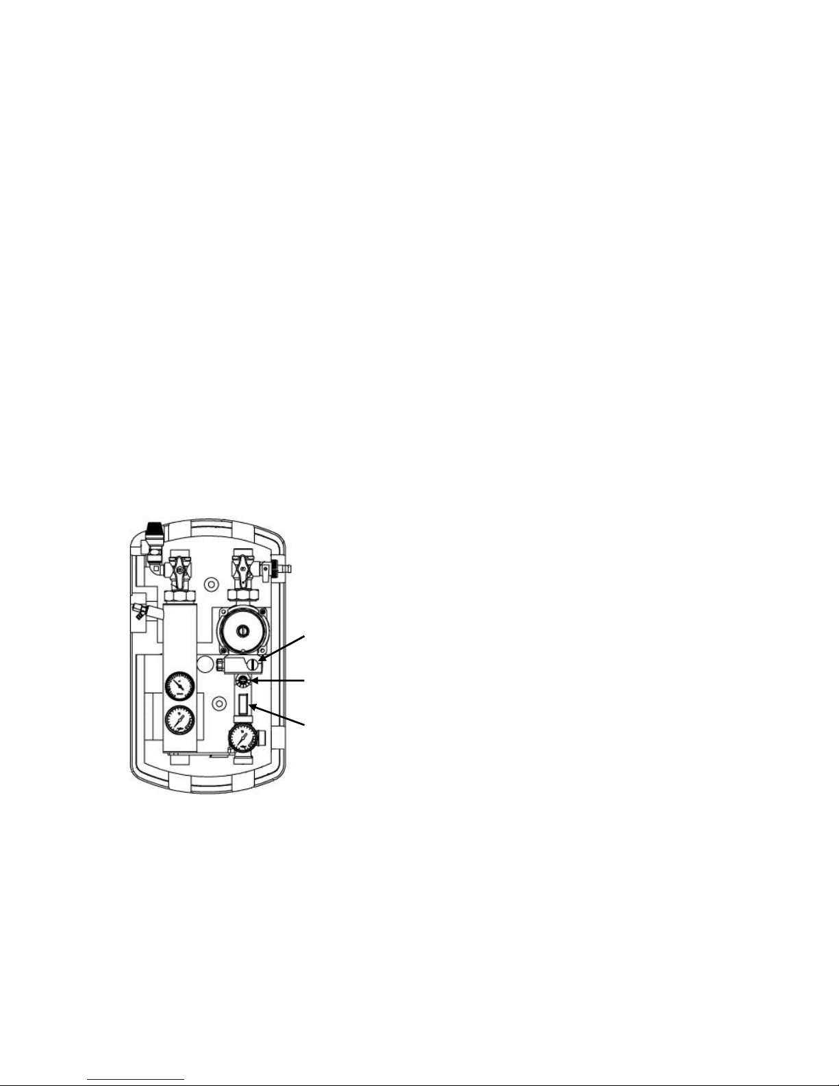
Set the pump speed to its minimum setting, 1, using the pump speed adjuster.
Turn the flow adjuster to its mid position, F, which gives the maximum flow rate.
Read the flow rate from the flow indicator. The reading is taken from the bottom edge of the
float body. Is the reading more than or equal to the required flow rate for the number of
manifolds fitted?
If NO:
Increase the pump speed until the reading is more than or equal to the required flow rate.
If YES:
Proceed to Step 4.5.2.
Figure 24: Circuit flow commissioning
4.5.2 Set flow adjuster
Set the flow adjuster by turning the valve until the reading is equal to the required flow rate.
If the required flow rate cannot be achieved at any flow adjuster setting, increase the pump
speed and repeat the process. If the required flow rate cannot be achieved at any pump
speed setting, it may be necessary increase the size of the pipework or to fit a higher head
pump. Consult the Customer Care Centre.
With the pump speed and flow adjuster correctly set to provide the required flow rate, access
the HND Menu and set HDN1 to Off. Ensure the circulating pump stops.
Pump Speed Adjuster
Flow Adjuster
Flow Indicator
Page 26

24
5 MAINTENANCE
This equipment must be inspected and serviced annually by a qualified professional in order
to maintain optimum efficiency and reliability and to prevent degradation or damage which
may not be covered by the product guarantee.
We recommend the system is serviced annually prior to the coldest months of winter.
In addition to annual servicing by a qualified professional, the system should be checked
periodically by the end user to identify any potential problems as soon as possible in the
unlikely event that they might occur.
5.1 Periodic System Check
On a regular basis, check the system pressure by reading the pressure gauge on the pump
station (refer to Figure 19 on Page 19). The pressure should be no less than 3 bar and no
more than 6 bar. If the pressure is outside this range, contact your installer / service
engineer.
5.2 Annual Maintenance
Using a proprietary test kit, assess the health and performance of the system by carrying out
the following checks.
5.2.1 Check installation
Check for any signs of physical damage to the system and repair if necessary.
Visually inspect the installation for any signs of leakage, particularly if the system pressure
has fallen below 3 bar. Any leakage must be rectified and the system re-pressurised and
bled using Warmflow Solar Fluid (SF~) and an appropriate filling station.
5.2.2 Check fluid health
CAUTION: The fluid may be EXTREMELY HOT!
Draw off a small amount of fluid via the bleed point using a section of suitable 8mm ID hose
(secured in place with an appropriate jubilee clip) to safely discharge the fluid into a suitable
container.
Visually inspect the fluid. When the fluid is new it is light green in colour, transparent and
has the consistency of mildly soapy water. If it is dark brown in colour, or has become thick,
it has degraded and should be replaced. Depending on the severity of the degradation,
flushing may be required before refilling. Consult the flushing fluid manufacturer.
Check the pH of the fluid. If it is 7.0 or less the fluid must be replaced.
5.2.3 Check performance
If there is adequate solar gain on the day of servicing, check the performance of the
installation by measuring the flow and return temperatures vs. the solar insolation.
Check the calibration of the T2 and T3 tanks sensors. They should measure within a few
degrees of a thermometer inserted in the tank sensor pockets.
Discuss the performance of the system with the end user. If they report the performance to
have decreased, and there is insufficient solar gain on the day of servicing to check, it may
be necessary to gain access to the roof to check the vacuum tubes. If any getters have
turned white the tube(s) affected will need to be replaced.
Page 27

25
5.2.4 Annual service checklist
For guidance only – NOT to be completed and returned
Collector inspection
1 Visual collector inspection
2 Visual inspection of the collector fixings
3 Visual inspection for potential leaks in the roof
4 Visual inspection of the thermal insulation on pipework
Solar circuit inspection
5 Visual inspection for potential leaks in the solar circuit at all joints and valve seals
6 Colour check of the heat transfer medium
7 Acidity check of the heat transfer medium (pH) (only if discoloured)
8 Frost protection level of the heat transfer medium checked
9 Operation of the pump station relief valve checked
10 If pump is noisy or system pressure fluctuates, flush air from system (using filling station)
11 System pressure (cold) checked (re-pressurise if necessary to 3.5 bar)
Control systems
12 Temperature sensor measurements verified
13 System flow rate checked and adjusted if necessary
Page 28

26
6 PRODUCT GUARANTEE
Warmflow Solar vacuum tube collectors, accessories and controls are supplied with a 2 year
part guarantee against defects of material or manufacture, conditional upon:
a) the system being installed and commissioned by competent persons in accordance
with the manufacturer’s and all relevant legislation, regulations and codes of practice
in force at the time;
b) it being used solely for the purpose of heating water through a suitable proprietary
heat exchanger compliant with current (at the time of installation) EU standards;
c) it not being modified in any way, misused or subject to neglect;
d) it not being subjected to frost, excessive or negative pressure, transient voltages or
lightening strike;
e) the collector not being exposed to direct sunlight prior the commissioning and
installation of the solar circuit and controls;
f) only ‘Warmflow Solar Fluid’ being used to fill the system;
g) the product being registered with Warmflow within 30 days of installation and the
guarantee registration completed and returned to Warmflow along with evidence of
the date of purchase;
h) the system being serviced annually by competent persons in accordance with the
manufacturer’s instructions and all relevant regulations and codes of practice in force
at the time;
i) each service record being completed and proof of purchase and servicing being
retained and made available to Warmflow in respect of any claim.
This guarantee is not transferable and excludes:
a) any failure caused by freezing, corrosion or breakage due to mishandling and/or
mechanical damage;
b) labour costs associated with the replacement of the product or its components;
c) consequential losses however caused.
This guarantee does not confer any rights other than those expressly set out above. The
guarantee is offered as an extra benefit and does not affect your statutory rights as a
consumer.
FAILURE TO COMMISSION, REGISTER AND ANNUALLY SERVICE THIS PRODUCT
WILL INVALIDATE ALL
GUARANTEES
In the event of a replacement component being required Warmflow will supply such part(s),
free of charge and freight paid, on the condition that the defective component is delivered,
freight paid, to Warmflow within 2 weeks of written notice being given to Warmflow of the
defect. Such replacement parts shall be covered under the terms of this guarantee to the
unexpired period of the aforementioned 2 year period.
An extended warranty of up to 20 years is available, details of which are available upon
request.
Page 29

27
7 INSTALLATION NOTES
Please use this section to record any important notes relevant to the installation which may
be required for future reference.
Page 30

WARMFLOW Engineering Company Limited
Lissue Industrial Estate, Moira Road, Lisburn BT28 2RF
Tel: 028 9262 1515 Fax: 028 9262 0869
WARMFLOW Customer Care Centre
UK: 028 9262 1515 ROI: 048 9262 1515
Email:
THIS MANUAL IS ACCURATE AT THE DATE OF PRINTING (E&OE)
BUT MAY BE SUPERSEDED AND SHOULD BE DISREGARDED IF
SPECIFICATIONS AND/OR APPEARANCES ARE CHANGED IN THE
INTERESTS OF CONTINUED PRODUCT IMPROVEMENT.
Q12-027 rev 02 May ‘10
Page 31
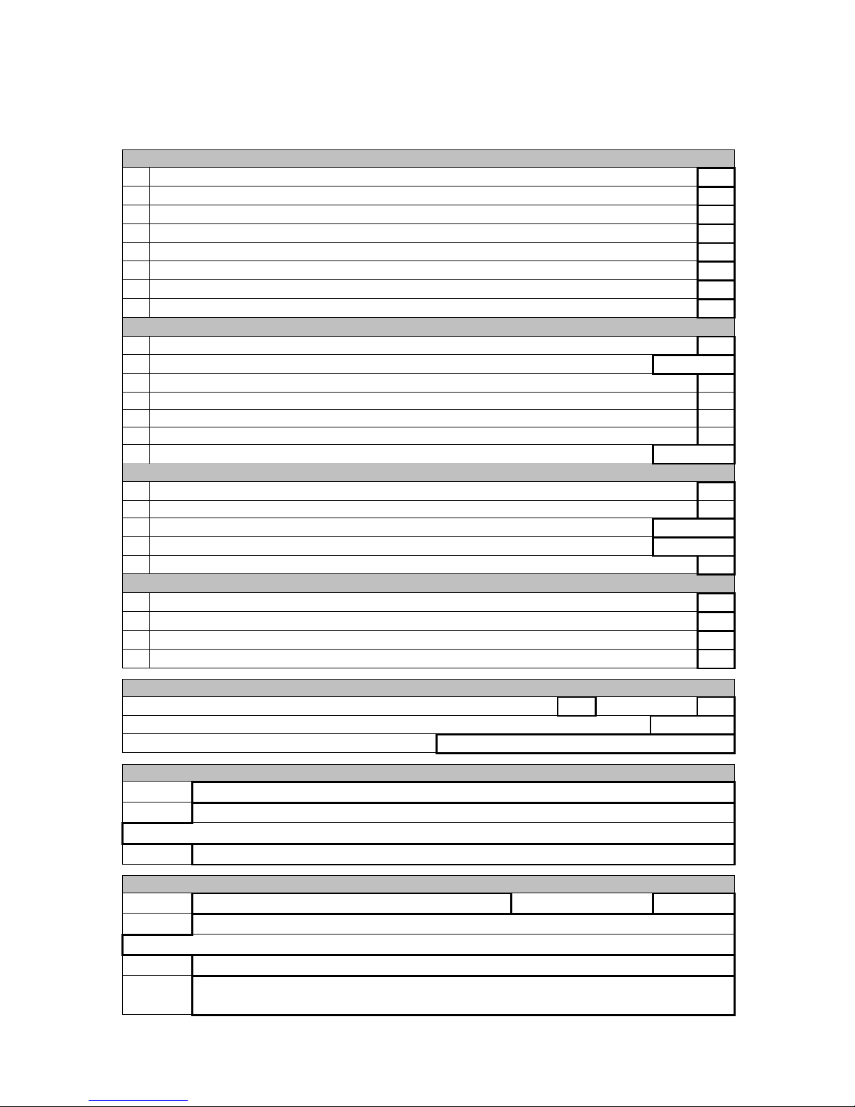
8 GUARANTEE REGISTRATION
To qualify for the product guarantee the equipment MUST be correctly commissioned and
the below guarantee registration completed and returned as instructed overleaf.
Failure to commission and register the product may invalidate ALL guarantees.
Installation Checklist
Tick or insert value
1 Collectors installed as instructed on a suitably strong section of roof?
(tick)
2 Collectors earthed / lightening-protected as instructed?
(tick)
3 Roof made weather-tight at mounting brackets and pipework / cable entries?
(tick)
4 Solder ring fittings and low temperature soldered joints NOT used?
(tick)
5 All pipework insulated with high temperature insulation?
(tick)
6 Cylinder controls fitted as instructed (e.g. motorised valves on unvented cylinders)
(tick)
7 Temperature sensors located, secured and wired as instructed?
(tick)
8 Pump station relief valve outlet plumbed to safe visible discharge?
(tick)
Commissioning
9 Expansion vessel bladder pressure checked (prior to system filling)?
(tick)
Bladder pressure
bar
10 System flushed then filled with Warmflow Solar Fluid
(tick)
11 System flushed of all air (filling station run for at least 45 minutes)
(tick)
12
System pressure tested and inspected for leaks at all joints and valve glands
(tick)
13 System pressure set?
(tick)
System pressure (cold)
bar
Control systems
14 Temperature sensor measurements verified?
(tick)
15 Circuit flow commissioning correctly completed?
(tick)
Pump speed setting
Flow rate
l/min
16 Boiler back-up controlled via solar system controller?
Handover
17 Basic function and operation of the system explained?
(tick)
18 Importance of checking system pressure explained?
(tick)
19 Need for annual servicing explained?
(tick)
20 All product literature left with the end user?
(tick)
System details
Collector type Flat Panel
(tick)
Vacuum Tube
(tick)
System size Total number of flat panels or vacuum tubes
Pump station serial number (format SDPS1-xxxx-xxx-xxx)
Installation address details
Name
Address
Telephone
Commissioning engineer’s details
Name Date of Commissioning
Address
Telephone
Signature
Page 32

Guarantee Registration
Please complete the Guarantee Registration Section overleaf then either remove this page
or copy / scan the form and return it to Warmflow using one of the 3 methods below:
By Post:
Using the prepaid envelope, or otherwise, to:
Warmflow Engineering Co Ltd
Appliance Registration Department
Lissue Industrial Estate
Moira Road
Lisburn
BT28 2RF
Northern Ireland
By fax:
028 9262 0869 (from Great Britain and Northern Ireland)
048 9262 0869 (from the Republic of Ireland)
By email:
 Loading...