

WarmFlow Boilerhouse B90HE, Utility U150HE, Utility U120HE, Boilerhouse B120HEU, Utility Pumped UP70HE User Manual
...
Boiler Manual
Incorporating: User Instructions
Installation Instructions
Service Instructions
Guarantee Terms & Conditions
High Efficiency
Condensing Boilers
For use with Kerosene only
Models covered by this manual:
B-Series
Boilerhouse B70HE B90HE B120HE
U-Series
Utility U70HE U90HE U120HE U150HE
Utility Pumped UP70HE UP90HE UP120HE UP150HE
Utility System US70HE US90HE US120HE
Utility Combi UC70HE UC90HE UC120HE
K-Series
Kabin Pak K70HE K90HE K120HE K150HE
Kabin Pak Pumped KP70HE KP90HE KP120HE KP150HE
Kabin Pak System KS70HE KS90HE KS120HE
Kabin Pak Combi KC70HE KC90HE KC120 HE
LEAVE THIS MANUAL WITH THE END USER
Cert. no. FM29884

COMMISSIONING
This appliance must be commissioned. Failure to commission the boiler will invalidate the
warranty. After commissioning, ensure that the Boiler Passport is completed and returned.
SERVICING
To ensure continued reliable operation, fuel economy and to validate the guarantee, it is
recommended that the boiler is serviced annually by a Warmflow or an OFTEC registered
technician.
NI Customers Only
Warmflow Engineering Service division (NI) provides an excellent back-up service, operating a
team of OFTEC trained engineers who can meet all the servicing, commissioning and
breakdown requirements for your appliance.
Tel: 028 9262 1515
Fax: 028 9262 2827
E-mail: service@warmflow.co.uk
Web: www.warmflow.co.uk
For Parts, Service Technical & Warranty Contact
Great Britain & N. Ireland, Tel: 028 9262 1515
Republic of Ireland, Tel: 048 9262 1515
LISBURN TELFORD
Lissue Industrial Estate, Moira Road, Unit 13, 32 Hortonwood,
Lisburn, Co. Antrim, N. Ireland, BT28 2RF Telford, TF1 7EU
Tel: (028) 9262 1515 Tel: (01952) 607 750
Fax: (028) 9262 0869 Fax: (01952) 603 983
E-mail: sales@warmflow.co.uk E-mail: salesgb@warmflow.co.uk
technical@warmflow.co.uk technical@warmflow.co.uk
service@warmflow.co.uk service@warmflow.co.uk

Page 1
CONTENTS
1 USER INSTRUCTIONS ......................................................................................................... 3
1.1 Dual Thermostat ......................................................................................................................... 3
1.2 High Limit Thermostat Reset ...................................................................................................... 3
1.3 Burner Lockout ........................................................................................................................... 3
1.4 System Pressure – System & Combi Boilers .............................................................................. 4
1.5 Filling Loop ................................................................................................................................. 4
1.6 Combi Control Panel .................................................................................................................. 4
2 CONDENSING BOILER INSTALLATION REQUIREMENTS ............................................... 5
3 BEFORE FITTING A COMBI BOILER THE INSTALLER MUST CHECK: .......................... 6
4 GENERAL INFORMATION ................................................................................................... 7
4.1 Introduction ................................................................................................................................ 7
4.2 General Requirements ............................................................................................................... 7
4.3 Combi General Requirements .................................................................................................... 8
4.4 Baffle Positioning........................................................................................................................ 9
4.5 Components ............................................................................................................................. 10
5 TECHNICAL DETAILS ....................................................................................................... 21
5.1 Combi Sequence of Operation Flow Chart ............................................................................... 21
5.2 Dimensions .............................................................................................................................. 22
5.3 Condensate Disposal ............................................................................................................... 27
5.4 Technical Data ......................................................................................................................... 28
6 ELECTRICITY SUPPLY & WIRING DETAILS ................................................................... 37
6.1 Dual-Safe Thermostat (Non-Combi Boilers) ............................................................................. 37
6.2 RDB Burner Control Box .......................................................................................................... 37
6.3 Combi Wiring Details ................................................................................................................ 38
6.4 Installation of a Warmflow Combi Optional Programmer (PC1) ................................................ 41
6.5 Remote Timers for Combis ....................................................................................................... 42
6.6 Optional Programmer (PC1) for Non-Combi Models ................................................................. 43
7 OIL SUPPLY ....................................................................................................................... 47
7.1 One Pipe Gravity System ......................................................................................................... 47
7.2 Two Pipe System ..................................................................................................................... 48
7.3 De-aerator System ................................................................................................................... 48
7.4 One Pipe Lift System ................................................................................................................ 49
7.5 Instructions for the use of Bio Fuel ........................................................................................... 50
8 FLUES ................................................................................................................................. 52
8.1 Flue Options, Components & Dimensions ................................................................................ 52
8.2 Flue Terminal Locations ........................................................................................................... 68
9 AIR SUPPLY FOR COMBUSTION & VENTILATION ......................................................... 69
9.1 Open Flue Boilers..................................................................................................................... 69
9.2 Balanced Flue Boilers – Boilers in a Compartment ................................................................... 69

Page 2
10 INSTALLATION REQUIREMENTS ................................................................................. 70
10.1 General Requirements ............................................................................................................. 70
10.2 Sealed Systems ....................................................................................................................... 71
10.3 Combi Domestic Hot Water ...................................................................................................... 72
11 BURNERS ....................................................................................................................... 73
11.1 RDB Burner .............................................................................................................................. 73
11.2 Oil Pump .................................................................................................................................. 73
11.3 Electrode Setting ...................................................................................................................... 74
11.4 Burner Start-Up Cycle .............................................................................................................. 74
11.5 Air Damper Adjustment ............................................................................................................ 74
12 COMMISSIONING & SERVICING ................................................................................... 75
12.1 Commissioning ......................................................................................................................... 75
12.2 Servicing .................................................................................................................................. 75
13 BURNER FAULT FINDING ............................................................................................. 76
13.1 Riello RDB................................................................................................................................ 76
14 COMBI FAULT FINDING ................................................................................................. 77
14.1 Central Heating ........................................................................................................................ 77
14.2 Domestic Hot Water ................................................................................................................. 78
15 OPTIONAL BOILER MOUNTED DIGITAL TIMER .......................................................... 79
15.1 Operating Instructions .............................................................................................................. 79
16 SPARES .......................................................................................................................... 83
16.1 RDB 2.2 Spares ....................................................................................................................... 83
16.2 RDB 3.2 Spares ....................................................................................................................... 84
16.3 Pipe Spares .............................................................................................................................. 85
16.3 Pipe Spares cont‟d ................................................................................................................... 86
16.4 Short Parts List - Boiler ............................................................................................................ 87
17 YOUR GUARANTEES, TERMS & CONDITIONS ........................................................... 88
Page 3
1 USER INSTRUCTIONS
1.1 Dual Thermostat
The radiator temperature is regulated via the boiler
control thermostat. The thermostat is user adjustable
from 45°C at its minimum setting (dial „0‟) to 75°C at its
maximum setting (dial „5‟). In order to provide an
additional level of safety there is a high limit thermostat
which has a cut off point of 110°C; this is factory set
and is not adjustable. If thermostat trips it needs to be
reset manually.
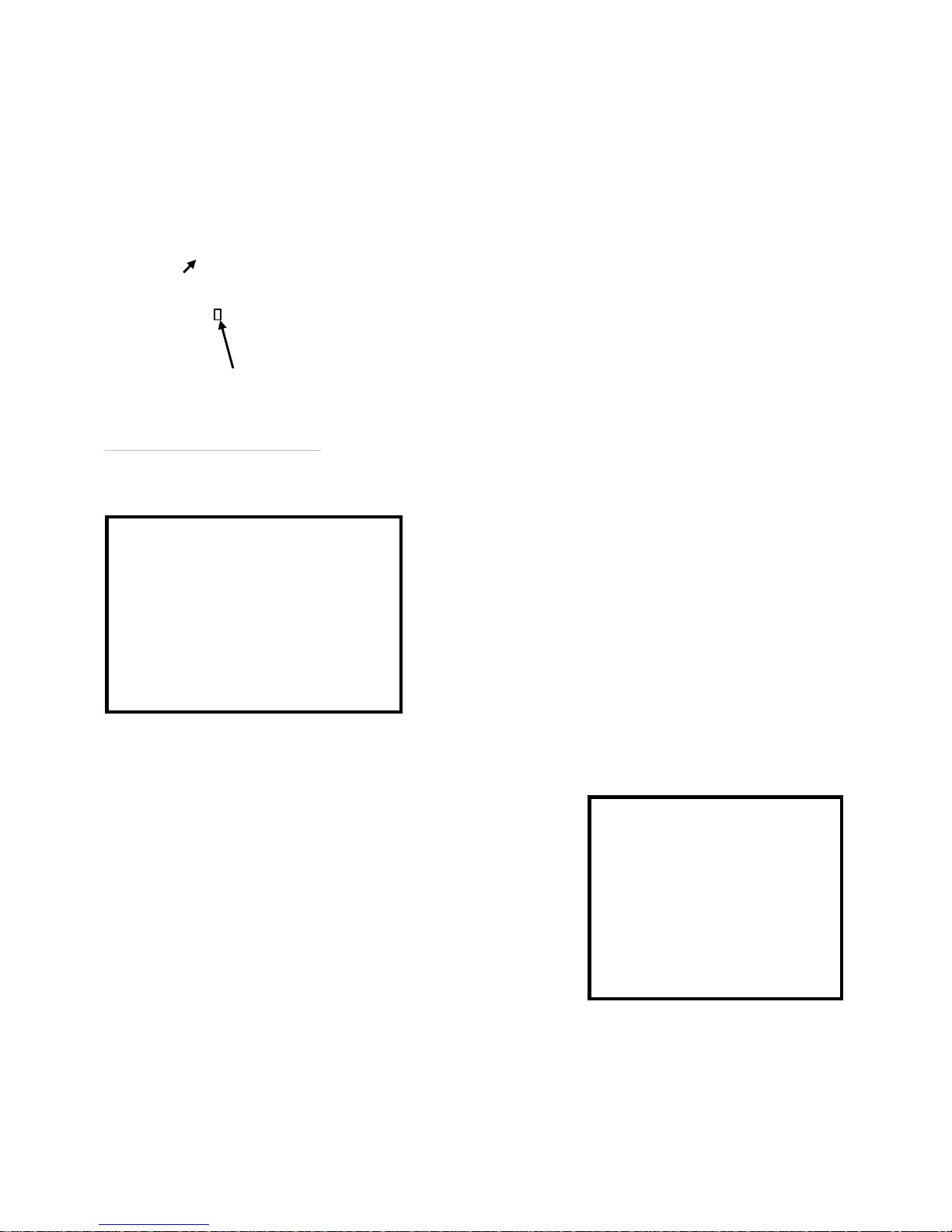
1.2 High Limit Thermostat Reset
If the high level thermostat trip has operated,
remove the reset cover by using a coin or
screwdriver (turning anti clockwise) and press
the small red button now exposed. Do not
press the reset button while the boiler is still hot
as this will cause damage to the thermostat.
1.3 Burner Lockout
When the pressure jet oil fired burner stops after
failing to fire the red reset button will be illuminated.
This indicates that there is a fault or there is no fuel
getting to the burner. The house holder should only
reset the burner twice in succession. If the burner
continues to lockout contact Warmflow or your
service engineer.
Control dial
Reset button

Page 4
1.4 System Pressure – System & Combi Boilers
When the boiler is connected to a sealed system the
system pressure should be periodically checked. The
minimum pressure, as indicated by the black needle,
is 0.5 bar when the boiler is cold and 2.5 bar when
the boiler is at normal operating temperature. If the
pressure is outside this range contact Warmflow or
your installer.
1.5 Filling Loop
If the system pressure falls below the minimum
(e.g., due to the removal of a radiator for
decorating purposes) then the system should be
topped up using the filling loop valve. After the
system has been topped up the pressure gauge
should read 1 bar when the system is cold. The
valve must be fully closed and the flexible filling
loop removed from the valve, expect a small
water loss from the pipe.
Special attention must be given to the
concentration of corrosion inhibitors in the system water where there is a need for
topping up. Concentrations must be restored to inhibitor manufacturers‟
recommendations and monitored going forward.
Frequent or routine topping up of the system should not be necessary and may
prove harmful to the appliance. Should topping up prove necessary on a frequent
or routine basis you must contact Warmflow or your installer.
1.6 Combi Control Panel
The heating control thermostat is user adjustable from 50°C to 80°C. In order to
provide an additional level of safety there is a high limit thermostat which has a cut
off point of 110°C; this is factory set and is not adjustable. The high limit
thermostat is located under the control panel to the left hand side, press button to
reset. As standard the panel is fitted with two on/off selector switches to control
hot water and central heating. These switches can be replaced by the optional two
channel digital programmer, instructions for use are provided in the main boiler
handbook.
This boiler must be serviced annually. Contact Warmflow for further details.
In the event of a breakdown please contact your commissioning engineer who
should then contact our service department whilst at your home, to report the
fault.
Filling Loop Ball Valve
System Pressure

Page 5
2 CONDENSING BOILER INSTALLATION REQUIREMENTS
The Warmflow condensing boiler can be fitted to most installations using standard
practices and techniques. There are however a number of considerations that
must be taken into account.
1. All existing systems must be properly flushed to remove any sediment/
sludge in order to prevent any blockage or reduction in efficiency of the
boiler.
2. The system must be fully pumped.
3. The primary difference between an ordinary boiler and a condensing boiler
is the condensate drain. The drain can be plumbed from the condensate
trap in any ordinary plastic pipe, eg, plastic overflow pipe, directly into the
household drain or soak away.
Any blockage in the drain could lead to an alteration in the combustion
settings because of partially blocked flueways.
Where the boiler is fitted into a basement a condensate pump may be
required.
4. As an indicator of the increased efficiency of a condensing boiler there may
be a visible plume of „steam‟ from the flue. Care needs to be exercised when
positioning the appliance and selecting the type of flue to ensure that the
plume does not cause a nuisance to the householder or to surrounding
properties.
As the water temperature in the system rises the pluming effect will diminish.
Even where pluming is not visible the boiler is still operating more efficiently
than a standard boiler.

Page 6
3 BEFORE FITTING A COMBI BOILER THE INSTALLER MUST
CHECK:
1. What the maximum hot water demand placed on the boiler is likely to be. Not
every installation is suitable for a Combi boiler. Systems requiring very high hot
water flow rates may be better suited with a Warmflow unvented cylinder.
2. That the mains are capable of supplying up to 24 litre/min with a minimum
dynamic pressure of 1.8 bar at the boiler. This is to ensure that the boiler can
achieve its maximum output. To protect the appliance and to prevent excessive
flow rates, a pressure reducing valve must be fitted to limit the maximum supply
pressure to 3 bar.
3. Where the mains water pressure is supplied via a borehole pump and
accumulator the pressure variation must not affect the thermostatic mixer valve.
Contact Warmflow for further details.
4. The hardness of the mains water supply. Systems with hard water must be
fitted with a suitable chemical scale preventer (e.g. Fernox Quantomat or
Combimate).
5. That the flow from any one hot water outlet does not exceed the maximum
recommended. This applies particularly to baths which are usually fitted with
larger taps and larger bore supply pipes. It may be necessary to restrict the flow to
these taps by reducing the bore of the supply pipework (eg 15mm) or by fitting a
restrictor into the pipework.
6. That any outlet, when opened, does not starve all the other outlets of hot water.
If more than one outlet is open at the same time then the total flow from all the
outlets should not exceed the maximum flow rate of the boiler.
7. That any showers being supplied with hot water by the boiler are compatible
with this type of appliance.
It should be noted that the boiler has been factory fitted with an 18 litre/min flow
restrictor.
The manufacturer‟s guarantees are void if the appliance is not installed and
commissioned in accordance with the recommendations made herein.

Page 7
4 GENERAL INFORMATION
4.1 Introduction
Note: All our domestic appliances have been independently tested and
accredited as exceeding the minimum SEDBUK efficiency levels required for
their type, in compliance with the Building Regulations Approved Document
L1A, L1B for England and Wales, the Building Standards (Scotland)
Regulations Section 6, Part F Northern Ireland and Part L Republic of
Ireland.
Warmflow oil fired condensing boilers are designed to burn Class C2 (28 sec
redwood) kerosene only and to be used on a fully pumped system, and are
suitable for connection to sealed heating systems.
As standard the Combi and System boilers are fitted with a system expansion
vessel, circulating pumps, filling loop, pressure gauge and safety valve. An
optional 7-day electronic programmer kit is also available for all Utility boiler
models.
The Combi can provide, at mains pressure domestic hot water without the need
for a storage cylinder.
The manufacturer‟s guarantees are void if the appliance is not installed and
commissioned in accordance with the recommendations made herein.
4.2 General Requirements
The installation of the boiler must be in accordance with the following regulations.
BS5410 : PART 1 Code of practice for oil firing.
BS5449 : PART 1 Forced circulation hot water systems.
BS7593 : Treatment of water in domestic hot water central heating systems.
Current Building Regulations: Part J England and Wales
Section 3 Scotland
Part L Northern Ireland
Part J Republic of Ireland
Current IEE Regulations
BS7074 : PART 1 Application Selection & Installation of Expansion Vessels

Page 8
The heating system should be installed by a competent installer in accordance
with the recommendations laid down by the building services compliance guide,
OFTEC and sound engineering practice.
In order to comply with building regulations, the boiler passport and or
OFTEC forms CD10 for installations and CD11 for commissioning should be
left with the customer. Alternatively the installation can be inspected and
approved by a building control officer.
4.3 Combi General Requirements
The boiler will have a DHW priority when both domestic hot water (DHW) and
central heating (CH) are selected. So if the flow switch is closed or the heat store
has not been satisfied the entire output of the boiler is directed to DHW before the
boiler will switch over to CH. When fully cold it can take up to 20 minutes for the
heat store of a 90,000 Btu/h combi to be satisfied, and slightly longer for a 70,000
Btu/h combi.
After a draw-off of 120L at 24L/min, with an average temperature rise of 32ºC, the
thermal store of a 90,000 Btu/h combi has a recovery time of approximately 7
minutes. A 70,000 Btu/h combi will take slightly longer to recover.
Note: If HW has not been selected no hot water can be produced even if the heat
store is up to temperature.
4.3.1 Pump Overrun
Where there is a build up of excess heat in the boiler primary heat exchanger and
the central heating has not been selected then the pump overrun thermostat will
operate. The excess heat will then be pumped into the heat store. Once the
temperature has fallen in the boiler and the pump overrun stat is satisfied, then
the hot water pump will stop.
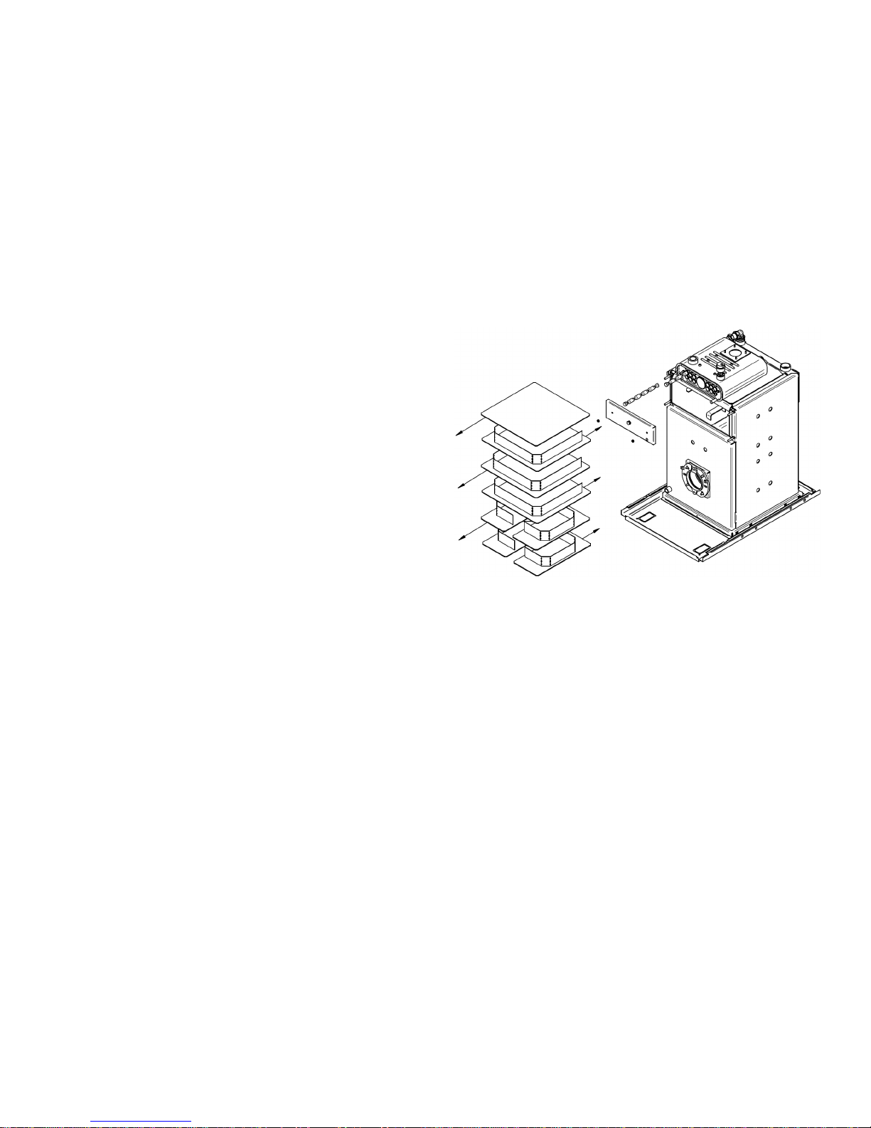
4.4 Baffle Positioning
Models up to 120 HE
The primary heat exchanger baffles consist of one
heavy baffle stack (4mm thick) at the bottom, 3 lighter
baffle stacks (3mm thick) in the middle and 1 baffle
plate (3mm thick) at the top. Upon installation or after
servicing, ensure the baffles are in the correct order
and correctly stacked. To achieve maximum efficiency
push the primary heat exchanger baffles in the direction
of the arrows as shown. The secondary heat exchanger
spring baffles must be fully inserted into the heat
exchanger tubes (narrow end first).
150 HE Models
The primary heat exchanger baffles consist of two halfwidth baffle stacks at the bottom, 3 full-width baffle
stacks in the middle and 1 baffle plate at the top. Upon
installation or after servicing, ensure the baffles are in
the correct order and correctly stacked.
To achieve maximum efficiency, push the primary heat
exchanger baffles in the direction of the arrows as
shown. The secondary heat exchanger spring baffles
must be fully inserted into the heat exchanger tubes
(narrow end first).
Page 9
4.5 Components
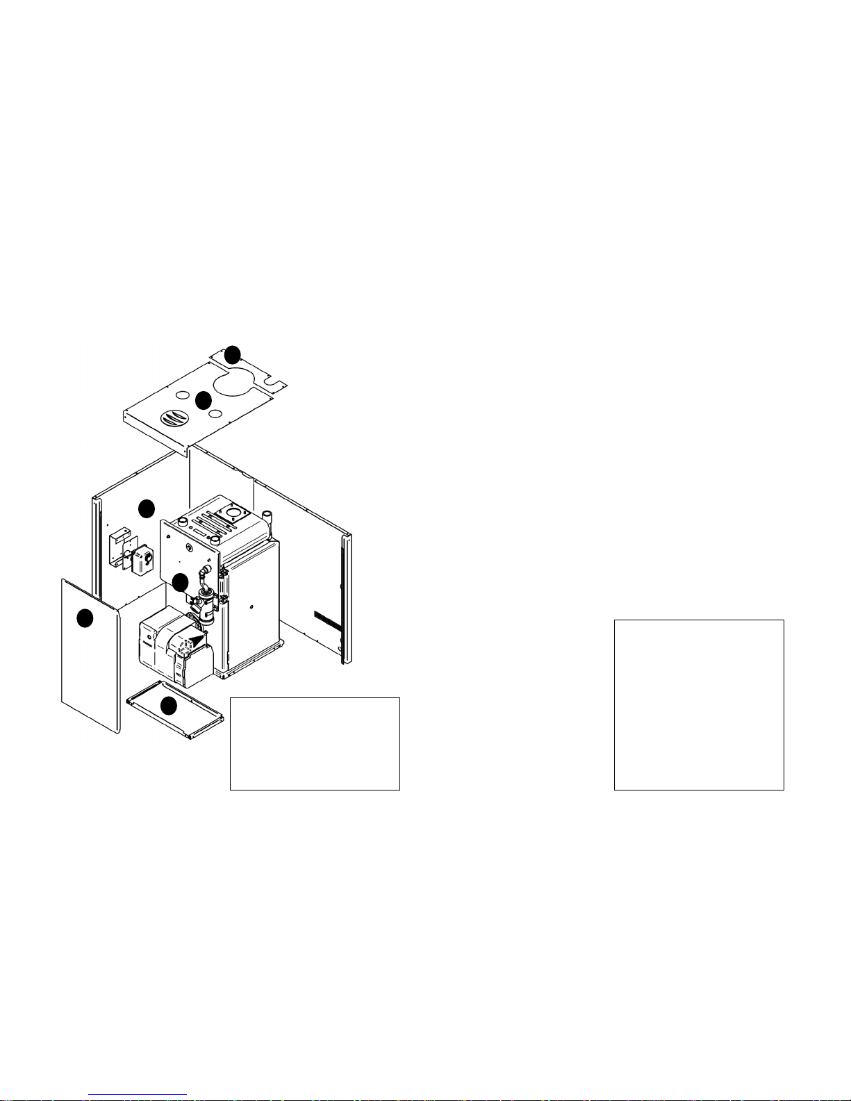
4.5.1 B-Series Boilerhouse – Casing Components & Key Components
1 4 5 6 2
Page 10
1. Boiler Assembly
2. Top Front Casing (removable)
3. Top Rear Casing (removable)
4. Sides & Rear Casing
5. Front Casing (removable)
6. Bottom Front Casing
1. Heat Exchanger
2. Condensing Unit
3. Auto Air Vent
4. Service Door
5. ‘Dual-Safe’ Thermostat
6. Heat Exchanger Baffles
7. Service Door
8. Service Door Cover
9. Condensate Trap
10. Riello RDB 2.2 Burner
11. Heating Flow Connection
12. Heating Return Connection

4.5.2 U-Series Utility – Casing Components
Models up to 120 HE
150 HE Models
Page 11

4.5.3 U-Series Utility – Pre-Wired (UHE)
Key Components
Models up to 120 HE
150 HE Models
Page 12

4.5.4 U-Series Utility – Pumped (UPHE)
Key Components
Models up to 120 HE
150 HE Models
Page 13

Page 14
4.5.5 U-Series Utility – System (USHE) - Key Components
4.5.6 U-Series Utility – Combi (UCHE) - Key Components

4.5.7 K-Series Kabin Pak – Casing Components
Models up to 120 HE
150 HE Models
Page 15

4.5.8 K-Series Kabin Pak - Pre-Wired (KHE)
Key Components
Models up to 120 HE
150 HE Models
Page 16

4.5.9 K-Series Kabin Pak - Pumped (KPHE)
Key Components
Models up to 120 HE
150 HE Models
Page 17

Page 18
4.5.10 K-Series Kabin Pak – System (KSHE) - Key Components
4.5.11 K-Series Kabin Pak – Combi (KCHE) - Key Components
Page 19
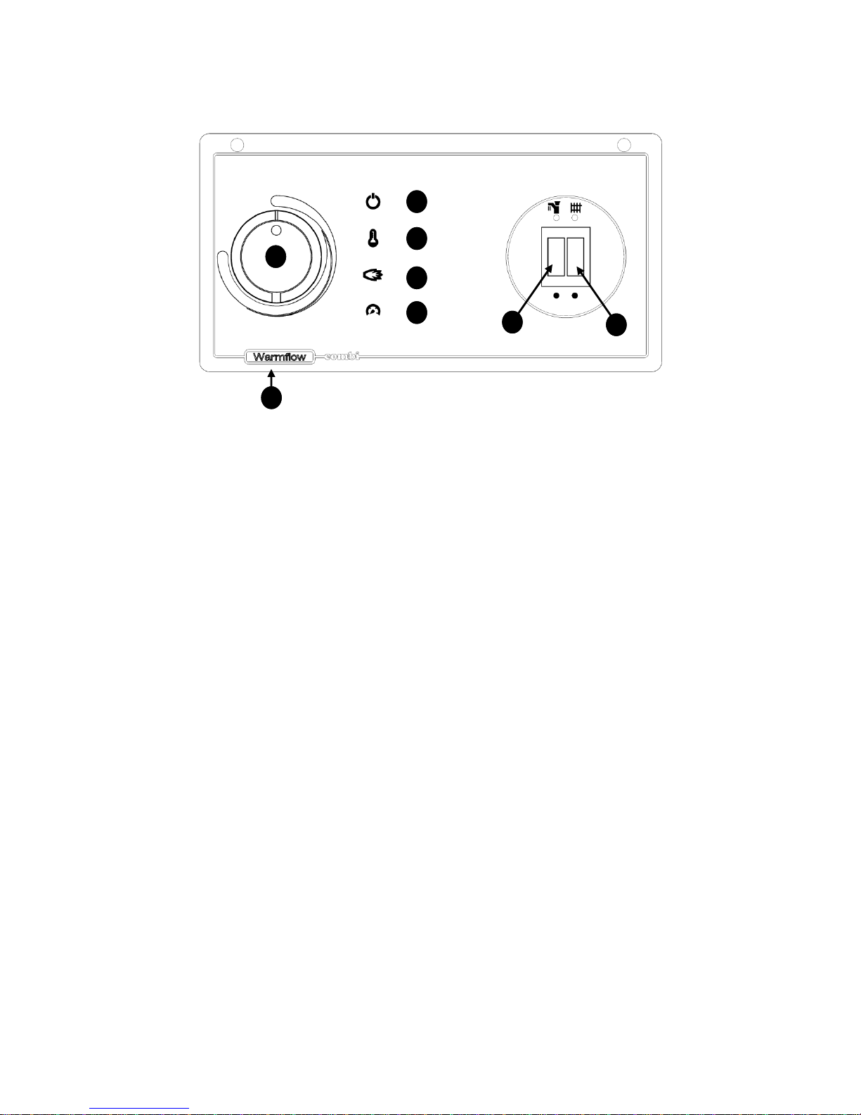
4.5.12 Combi Control Panel Layout
1) Heating Temperature Control
The heating temperature control
adjusts the temperature of the central
heating water flowing from the boiler
to the radiators. Turn the dial
clockwise towards red to increase the
temperature and anticlockwise
towards blue to reduce.
2) High Limit Reset
The high limit thermostat protects the
boiler against overheating and is
factory set to 110°C (not adjustable).
Should this thermostat ever trip, it
must be reset by pressing the small
red button underneath the control
panel towards the left hand side. Do
NOT reset when the boiler is still hot.
3) Hot Water On/Off Switch
4) Heating On/Off Switch
Heating and Hot Water modes are
controlled via the on/off switches
unless a remote time clock has been
fitted. Consult your installer.
5) Mains On Lamp
If this lamp is not lit there may be no
power coming to the appliance.
Check fuses and heating controls.
6) High Limit Lamp
If this lamp is lit, the high limit
thermostat has tripped. Press the
high limit reset (2).
7) Burner Lockout Lamp
If this lamp is lit, the burner has
locked out after failing to fire. Press
the red reset button on the front of the
burner.
8) Low Pressure Lamp
If this lamp is lit, the system pressure
has fallen below 0.3 bar. Refer to the
instructions in Sections 1.4 and 1.5.
Additionally, top up the pressure until
the light goes out then release
pressure via the pressure relief valve
until system pressure is 1 bar when
the boiler is cold.
1
2 5 6
7
8
(underneath)
3
4

Page 20
4.5.13 Combi Pipe Layout (UCHE & KCHE Models)
Page 21
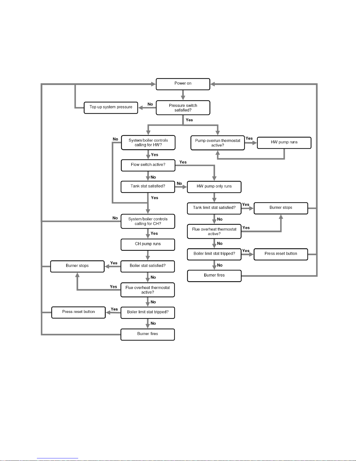
5 TECHNICAL DETAILS
5.1 Combi Sequence of Operation Flow Chart
Page 22
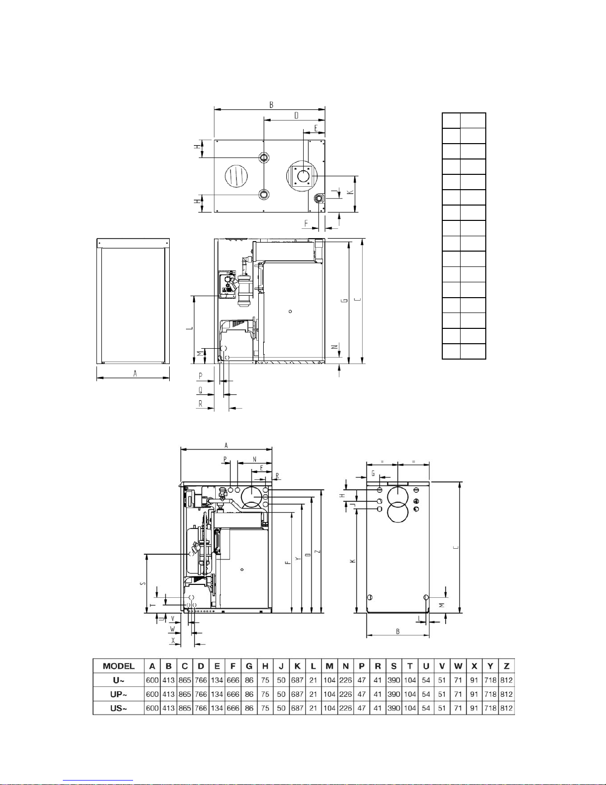
5.2 Dimensions
5.2.1 B-Series Boilerhouse (B70HE, B90HE & B120HE Models)
A
395 B 600 C 685 D 332 E 118 F 34 G 664 H 97 J 77 K 197 L 371 M 85 N 35 P 30 Q 50 R 80
5.2.2 U-Series Utility (UHE, UPHE & USHE Models up to 120HE)

Page 23
5.2.3 U-Series Utility (150HE Models)
5.2.4 U-Series Utility (UCHE Models)

Page 24
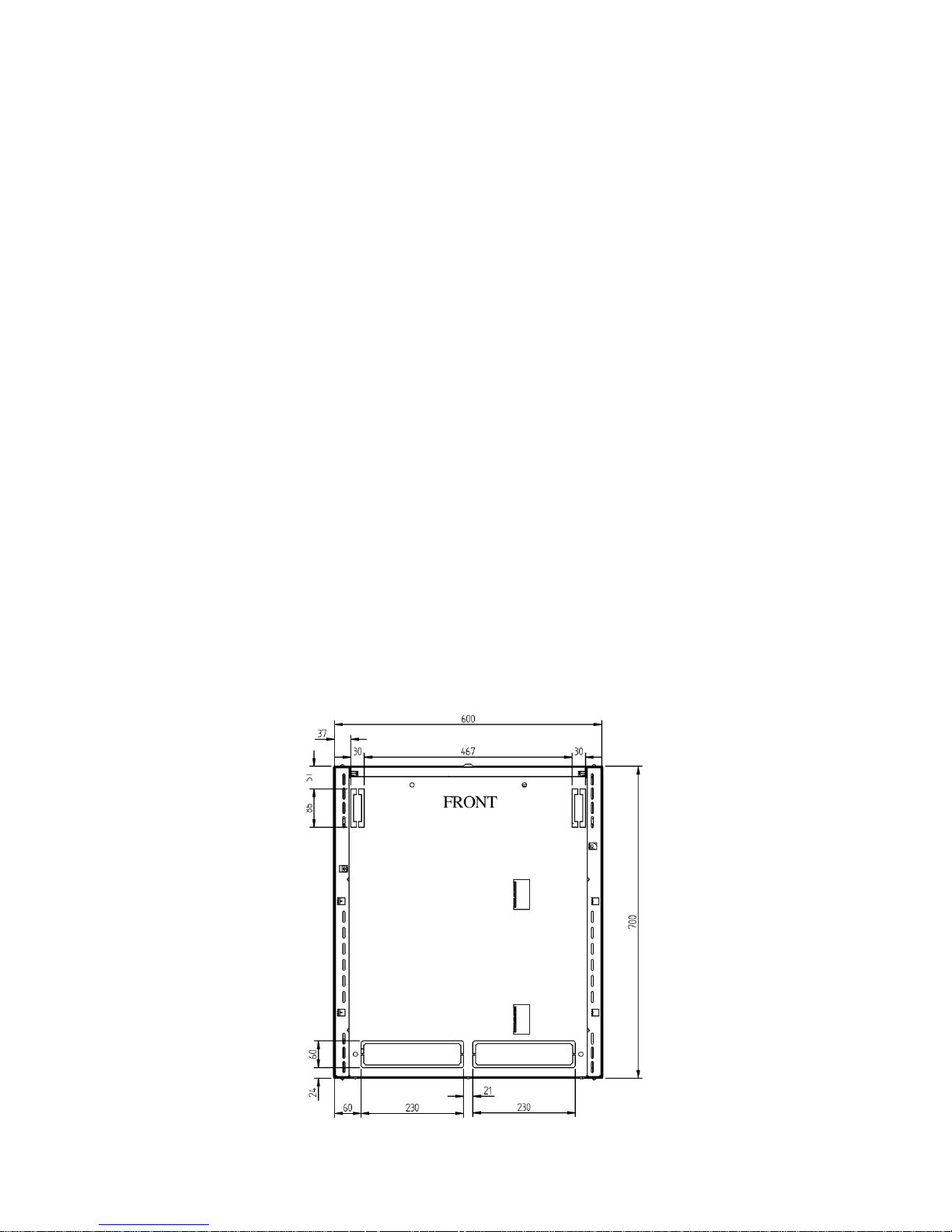
5.2.5 K-Series Kabin Pak (KHE, KPHE & KSHE Models up to 120HE)
5.2.6 K-Series Kabin Pak Base Tray (KHE, KPHE & KSHE Models up to
120HE)

Page 25
5.2.7 K-Series Kabin Pak (150HE Models)
5.2.8 K-Series Kabin Pak Base Tray (150HE Models)
Page 26
5.2.9 K-Series Kabin Pak (KCHE Models)
5.2.10 K-Series Kabin Pak Base Tray (KCHE Models)
 Loading...