

WarmFlow Direct DI250UV, Direct DI90UV, Direct DI150UV, Indirect IN120UV, Direct DI300UV User Instructions
...
Cylinder Manual
Direct
DI90UV
DI120UV
DI150UV
DI180UV
DI210UV
DI250UV
DI300UV
Indirect
IN120UV
IN150UV
IN180UV
IN210UV
IN250UV
IN300UV
Eco Direct
ED180UV
ED210UV
ED250UV
ED300UV
Twin Coil
TW180UV
TW210UV
TW250UV
TW300UV
Triple Coil
TR250UV
TR300UV
Incorporating: User Instructions
Installation Instructions
Commissioning Instructions
Maintenance Instructions
Unvented Cylinders
Mains pressure water heaters
EN 12897:2006
Products covered by this manual:
LEAVE THIS MANUAL WITH THE END USER

INSTALLATION, COMMISSIONING & SERVICING
This appliance must be installed as described herein and the installation commissioned by
competent persons as instructed. The Guarantee Registration section of the separate Cylinder
Passport supplied with the product must be completed and the Guarantee Registration only
returned to the manufacturer with proof of purchase (e.g. receipts / invoices).
This appliance must be serviced annually by competent persons, the Service Record section of
the separate Cylinder Passport completed on each occasion and proof of servicing (e.g.
receipts / invoices) retained.
The complete guarantee policy statement is included in Section 9, page 21.
FAILURE TO COMMISSION, REGISTER AND ANNUALLY SERVICE THIS
PRODUCT WILL INVALIDATE ALL GUARANTEES
TECHNICAL, SPARES & GUARANTEE CLAIMS
For technical advice about the installation, commissioning, servicing or use of this appliance,
please contact the Warmflow Customer Care Centre by post, phone, fax or email at the
addresses below. Please also refer to our website.
Should replacement components be required, a list of available spares is provided in Section
8.3, page 19.
In the unlikely event that replacement components might be required within the guarantee
period, please notify the Customer Care Centre in writing, by post, fax or email, stating the
nature of the fault and the part number of the replacement components required.
Warmflow Customer Care Centre
Warmflow Engineering
Lissue Industrial Estate
Moira Road
Lisburn
BT28 2RF
Northern Ireland
Telephone
United Kingdom: 028 9262 1515
Republic of Ireland: 048 9262 1515
Facsimile
United Kingdom: 028 9262 0869
Republic of Ireland: 048 9262 0869
Email
technical@warmflow.co.uk
Website
www.warmflow.co.uk

CONTENTS
1 User Instructions ................................................................................................................. 2
1.1 Cylinder Thermostat ................................................................................................................... 2
1.2 Immersion Thermostat ............................................................................................................... 2
1.3 Discharge ................................................................................................................................ ... 2
2 Installation Requirements ................................................................................................... 3
3 Handling and Storage ......................................................................................................... 4
4 Standard Equipment ........................................................................................................... 4
5 Technical Data ..................................................................................................................... 4
5.1 General ...................................................................................................................................... 4
5.2 Direct Cylinders .......................................................................................................................... 5
5.3 Indirect Cylinders........................................................................................................................ 6
5.4 Eco Direct Cylinders ................................................................................................................... 7
5.5 Twin Coil Cylinders ..................................................................................................................... 8
5.6 Triple Coil Cylinders ................................ ................................................................ ................... 9
6 Installation ......................................................................................................................... 10
6.1 Cylinder Location...................................................................................................................... 10
6.2 Hot & Cold Water Connections ................................................................................................. 10
6.3 Primary, Renewable & Tertiary Circuits .................................................................................... 11
6.4 Tundish .................................................................................................................................... 11
6.5 Expansion Vessel ..................................................................................................................... 11
6.6 Hard water................................................................................................................................ 11
6.7 Pipework Configurations........................................................................................................... 12
6.8 Discharge Pipework ................................................................................................................. 13
6.9 Worked Example ...................................................................................................................... 15
6.10 Electrical Installation ................................................................................................................. 16
7 Commissioning.................................................................................................................. 18
7.1 Draining .................................................................................................................................... 18
8 Maintenance ....................................................................................................................... 19
8.1 Regular Maintenance ............................................................................................................... 19
8.2 Inspection Access .................................................................................................................... 19
8.3 Replacement Parts ................................................................................................................... 19
8.4 Fault Finding ............................................................................................................................ 20
9 Guarantee ........................................................................................................................... 21
10 End-of-Life Information .................................................................................................. 22
10.1 Safety Risks ................................................................ ............................................................. 22
10.2 Disassembly of the Product ...................................................................................................... 22
10.3 Casing and key components .................................................................................................... 23
Page 1 of 23

1 USER INSTRUCTIONS
Control dial
Reset button
Control dial
Reset button
This appliance is not intended for use by persons (including children) with reduced physical,
sensory or mental capabilities, or lack of experience and knowledge, unless they have been
given supervision or instruction concerning use of the appliance by a person responsible for
their safety. Children should be supervised to ensure that they do not play with the appliance.
The temperature of the hot water can be adjusted, and should ideally be set to 60°C (the
position indicated in the diagram below). A higher setting uses more energy and more fuel.
When a hot tap is turned on there may be a short surge of water – this is quite normal with
unvented systems and does not mean there is a fault. When you first fill a basin the water may
sometimes appear milky. This is due to air bubbles in the water which will clear very quickly.
1.1 Cylinder Thermostat
All cylinders (except Direct models) are fitted with one or more
cylinder thermostats to control the heat input to the cylinder from a
remote heat source, such as a boiler, heat pump or solar thermal
installation. The temperature of each cylinder thermostat is
adjustable between nominally 40°C and 70°C. Turn the control
knob clockwise to increase temperature, and anticlockwise to
decrease.
Each cylinder thermostat has a built-in manually reset safety
thermostat which will ‘lock out’ in the event of the cylinder
overheating and which will need to be reset in order to restore
operation. Remove the lock-out cover and depress the red button
to reset.
1.2 Immersion Thermostat
Isolate ALL electrical supplies to the appliance before removing the immersion cover.
All cylinders are supplied with one or more immersion heaters to
allow the cylinder to be heated electrically. Each immersion
heater has an immersion thermostat, the temperature of which is
adjustable between nominally 10°C and 70°C. Remove the
immersion heater cover and turn the control dial anticlockwise to
increase temperature, and clockwise to decrease.
Each immersion thermostat also has a built-in manually reset
safety thermostat which will ‘lock out’ in the event of the cylinder
overheating and which will need to be reset in order to restore
operation. Remove the immersion heater cover and depress the
red button to reset.
1.3 Discharge
If cold/warm water is discharged from the cylinder via the tundish, call your installer.
The pressure relief valves should be operated regularly to remove lime deposits and to verify
they are not blocked.
If very hot water is discharged, immediately switch off ALL heat sources (which may include
boilers, heat pumps, solar thermal systems and immersion heaters), isolate their electrical
supplies and call your installer.
Page 2 of 23

2 INSTALLATION REQUIREMENTS
Prior to installing this unvented hot water cylinder, please confirm that:
a) The mains water supply is capable of achieving a minimum flow rate of 20 litres per
minute at a minimum dynamic pressure of 1.5 bar at all times. If this performance
cannot be achieved the installation of an unvented cylinder may not be suitable.
b) The maximum mains supply pressure at any time does not exceed 12 bar. If this is the
case an additional ‘special’ pressure reducing valve (not supplied) may be required.
c) The mains water supply is from a public source (i.e. not from a private borehole) and that
the hardness of the water is less than 200 mg/litre. Where hardness in excess of 200
mg/litre is experienced, a suitable and effective hard water treatment must be installed.
d) All circuits supplying heat to the heat exchanger coils of any cylinder (not applicable to
direct cylinders) are fully pumped (gravity circulation is NOT suitable).
e) The pipework supplying the hot water taps is capable of withstanding a maximum
pressure of 7 bar at a temperature of 90°C.
This appliance must be installed vertically (not on its side) in a frost-free indoor location.
The installation of this appliance is subject to the Building Regulations:
England & Wales Building Regulation G3
Scotland Technical Standard P3
Northern Ireland Building Regulations P5
Republic of Ireland Technical Guidance Document Part L
The appliance and installation must be commissioned as described herein and the Guarantee
Registration section of the separate Cylinder Passport completed and returned to the
manufacturer.
FAILURE TO COMMISSION, REGISTER AND ANNUALLY SERVICE THIS
PRODUCT WILL INVALIDATE ALL GUARANTEES
Under no circumstances must the factory fitted temperature & pressure relief valve be
removed. Removal of the valve would create an extremely dangerous situation and
would invalidate all guarantees.
Page 3 of 23

3 HANDLING AND STORAGE
Direct
Indirect
Eco Direct
Twin Coil
Triple Coil
OPERATING DATA
Operating pressure (bar)
3.0
3.0
3.0
3.0
3.0
Maximum design pressure (bar)
6.0
6.0
6.0
6.0
6.0
Maximum supply pressure to inlet group (bar)
12.0
12.0
12.0
12.0
12.0
Expansion vessel bladder pre-charge pressure (bar)
3.0
3.0
3.0
3.0
3.0
SAFETY DEVICE SETTINGS
Pressure reducing valve (bar)
3.0
3.0
3.0
3.0
3.0
Expansion valve (bar)
6.0
6.0
6.0
6.0
6.0
Cylinder thermostat limit temperature (°C)
n/a
80
80
80
80
Immersion thermostat limit temperature (°C)
80
80
80
80
80
Temperature & pressure relief (T&P) valve (°C / bar)
90/7.0
90/7.0
90/7.0
90/7.0
90/7.0
T&P valve temperature probe length (mm)
102
102
102
102
102
HEAT TRANSFER COILS
Maximum circuit temperature (renewable coil) (°C)
n/a
n/a
120
120
120
Maximum circuit temperature (other coils) (°C)
n/a
85
n/a
85
85
Maximum circuit pressure (all coils) (bar)
n/a
6.0
6.0
6.0
6.0
Prior to installation this product should be handled with care and stored upright in a dry location
and in its original packaging.
4 STANDARD EQUIPMENT
Before commencing installation check that all the listed components have been supplied:
1. Temperature & pressure relief valve (factory-fitted)
2. Control thermostats (factory-fitted) (not applicable to Direct models)
3. Unvented kit including:
a. Inlet group
b. Expansion vessel
c. Tundish
4. Immersion heater(s) (packaged inside the unvented kit)
One 2-port motorised zone valve is supplied with Indirect, Twin Coil and Triple Coil models only,
for use on the primary circuit.
Note: This stainless steel cylinder requires no corrosion protection device e.g. anode.
5 TECHNICAL DATA
5.1 General
Table 1: General data (Indirect & Twin Coil models)
Page 4 of 23
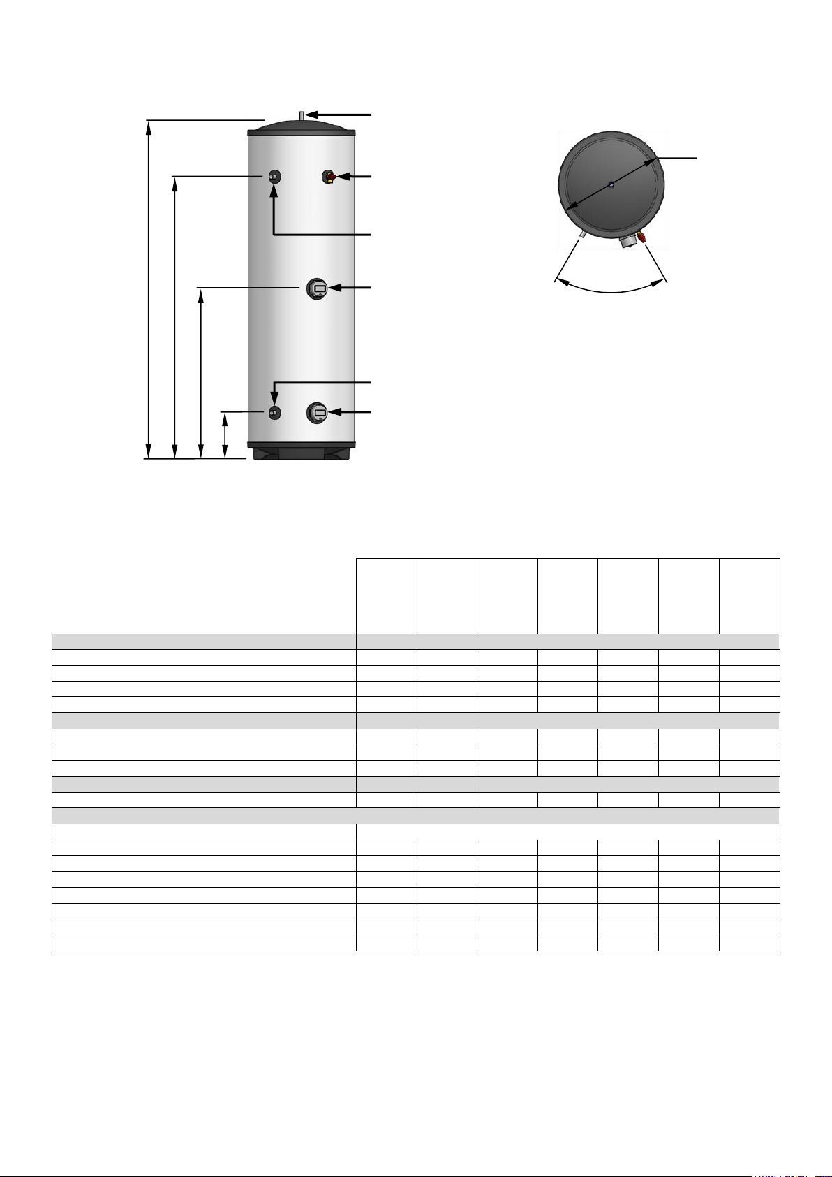
5.2 Direct Cylinders
DI90UV
DI120UV
DI150UV
DI180UV
DI210UV
DI250UV
DI300UV
DIMENSIONS
(A) Height (mm)
767
952
1142
1327
1517
1767
2077
(B) Secondary return connection / T&P (mm)
n/a
n/a
n/a
n/a
1223
1473
1783
(C) Upper immersion (mm)
n/a
482
577
670
765
890
1045
(D) Cold inlet connection / Lower immersion (mm)
243
243
243
243
243
243
243
OPERATING DATA
Cold water capacity (litres)
90
120
150
180
210
250
300
Weight when full (kg)
110
140
180
210
240
290
350
Standing heat loss (kWh/24h)
0.92
1.15
1.31
1.40
1.66
1.92
2.07
PERFORMANCE
Heat up time by lower immersion only (mins)
89
121
154
198
237
287
345
FICHE DATA
Supplier Name
Warmfllow
Supplier Model Identifier
DI90
DI120
DI150
DI180
DI210
DI250
DI300
Declared Load Profile
M M M L L
XL
XL
Energy Efficiency Class
D E D C D C C
Water Heating Energy Efficiency, ηwh (%)
34
30
36
38
37
39
39
Annual Electrical Consumption, AEC (kWh)
1541
1742
1452
2745
2799
4369
4351
Thermostat Setting (°C)
60
60
60
60
60
60
60
Sound Power Level (dB)
15
15
15
15
15
15
15
60°
Ø550
D
C
B
A
Hot Outlet (22mm)
Cold Inlet (22mm)
Temperature & Pressure
Relief Valve (15mm)
Upper Immersion Heater
Secondary Return (22mm)
Lower Immersion Heater
Figure 1: Direct cylinders components & dimensions
Table 2: Direct cylinder data
Page 5 of 23
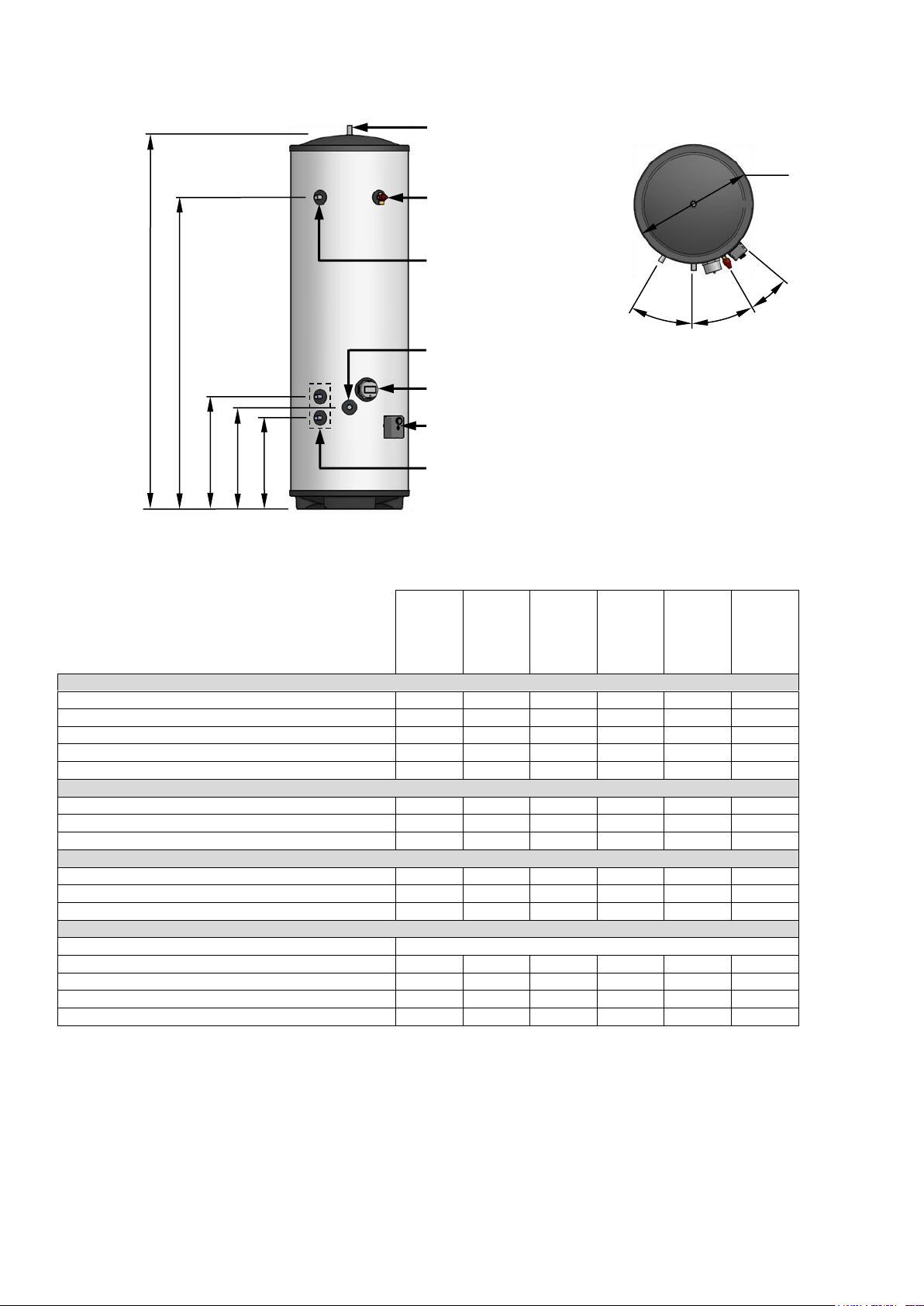
5.3 Indirect Cylinders
IN120UV
IN150UV
IN180UV
IN210UV
IN250UV
IN300UV
DIMENSIONS
(A) Height (mm)
952
1142
1327
1517
1767
2077
(B) Secondary return connection (mm)
n/a
n/a
n/a
1223
1473
1783
(C) Primary coil upper connection (mm)
462
462
532
532
532
532
(D) Cold inlet connection (mm)
412
412
482
482
482
482
(E) Primary coil lower connection (mm)
362
362
432
432
432
432
OPERATING DATA
Cold water capacity (litres)
120
150
180
210
250
300
Weight when full (kg)
140
180
210
250
290
350
Standing heat loss (kWh/24h)
1.15
1.31
1.40
1.66
1.92
2.07
COIL PERFORMANCE (EN12897)
Primary coil rating @ 15L/min (kW)
17.5
17.2
21.3
19.9
22.2
20.4
Primary coil pressure drop @ 15L/min (mbar)
54
54
67
67
67
67
Heat up time by primary coil (mins)
19.1
24.9
24.7
31.4
33.6
41.4
FICHE DATA
Supplier Name
Warmflow
Supplier Model Identifier
IN120
IN150
IN180
IN210
IN250
IN300
Energy Efficiency Class
A B B B C
C
Standing Loss (W)
36
55
58
60
84
86
Storage Volume (litres)
115
146
175
205
245
290
Ø550
E
C
B
Hot Outlet (22mm)
Cold Inlet (22mm)
Temperature & Pressure
Relief Valve (15mm)
Secondary Return (22mm)
Primary Coil Connections (22mm)
Primary Coil Thermostat
Immersion Heater
D
A
30°
30°
20°
Figure 2: Indirect cylinders components & dimensions
Table 3: Indirect cylinder data
Page 6 of 23
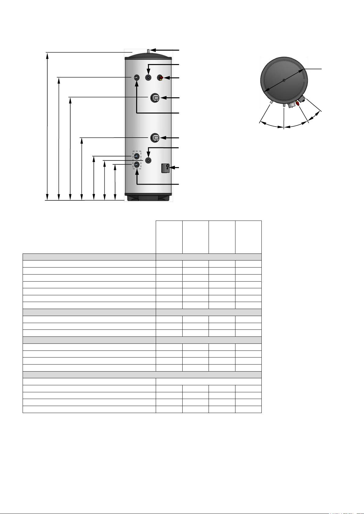
5.4 Eco Direct Cylinders
ED180UV
ED210UV
ED250UV
ED300UV
DIMENSIONS
(A) Height (mm)
1327
1517
1767
2077
(B) Secondary return connection (mm)
n/a
1223
1473
1783
(C) Upper immersion (mm)
891
1078
1230
1540
(D) Lower immersion (mm)
596
752
752
1062
(E) Renewable coil upper connection (mm)
532
532
532
532
(F) Cold inlet connection (mm)
482
482
482
482
(G) Renewable coil lower connection (mm)
432
432
432
432
OPERATING DATA
Cold water capacity (litres)
180
210
250
300
Weight when full (kg)
210
250
290
350
Standing heat loss (kWh/24h)
1.40
1.66
1.92
2.07
PERFORMANCE
Renewable coil rating @ 15L/min (kW)
21.4
20.2
21.8
19.3
Renewable coil pressure drop @ 15L/min (mbar)
67
67
67
67
Heat up time by lower immersion only (mins)
127
138
184
188
Dedicated renewable volume (litres)
65
90
110
145
FICHE DATA
Supplier Name
Warmflow
Supplier Model Identifier
ED180
ED210
ED250
ED300
Energy Efficiency Class
B
B C C
Standing Loss (W)
58
60
84
86
Storage Volume (litres)
175
205
245
290
30°
Ø550
G
E
D
Hot Outlet (22mm)
Cold Inlet (22mm)
Temperature & Pressure
Relief Valve (15mm)
Secondary Return (22mm)
Renewable Coil Connections (22mm)
Renewable Coil Thermostat
Lower Immersion Heater
F
30°
20°
Upper Immersion Heater
Sensor Pocket (1/2”)
C
B
A
Figure 3: Eco Direct cylinders components & dimensions
Table 4: Eco Direct cylinder data
Page 7 of 23

5.5 Twin Coil Cylinders
TW180UV
TW210UV
TW250UV
TW300UV
DIMENSIONS
(A) Height (mm)
1327
1517
1767
2077
(B) Secondary return connection (mm)
n/a
1223
1473
1783
(C) Primary coil upper connection (mm)
973
1078
1078
1388
(D) Primary coil lower connection (mm)
873
978
978
1288
(F) Renewable coil upper connection (mm)
532
532
532
532
(F) Cold inlet connection (mm)
482
482
482
482
(G) Renewable coil lower connection (mm)
432
432
432
432
OPERATING DATA
Cold water capacity (litres)
180
210
250
300
Weight when full (kg)
210
250
290
350
Standing heat loss (kWh/24h)
1.40
1.66
1.92
2.07
COIL PERFORMANCE (EN12897)
Primary coil rating @ 15L/min (kW)
20.7
21.3
20.2
21.0
Primary coil pressure drop @ 15L/min (mbar)
54
54
54
54
Heat up time by primary coil @ 15L/min (mins)
15.7
16.3
22.6
21.9
Renewable coil rating @ 15L/min (kW)
20.7
22.3
22.0
20.7
Renewable coil pressure drop @ 15L/min (mbar)
67
67
67
67
Dedicated renewable volume (litres)
70
105
105
155
FICHE DATA
Supplier Name
Warmflow
Supplier Model Identifier
TW180
TW210
TW250
TW300
Energy Efficiency Class
B
B C C
Standing Loss (W)
58
60
84
86
Storage Volume (litres)
175
205
245
290
30°
Ø550
G
E
D
Hot Outlet (22mm)
Cold Inlet (22mm)
Temperature & Pressure
Relief Valve (15mm)
Secondary Return (22mm)
Renewable Coil Connections (22mm)
Renewable Coil Thermostat
Immersion Heater
F
30°
20°
C
B
A
Primary Coil Connections (22mm)
Primary Coil Thermostat
Figure 4: Twin Coil cylinders components & dimensions
Table 5: Twin Coil cylinder data
Page 8 of 23

5.6 Triple Coil Cylinders
TR250UV
TR300UV
DIMENSIONS
(A) Height (mm)
1767
2077
(B) Secondary return connection (mm)
1473
1783
(C) Tertiary coil ‘A’ upper connection (mm)
1403
1683
(D) Primary coil ‘B’ upper connection (mm)
1363
1643
(E) Tertiary coil ‘A’ lower connection (mm)
564
844
(F) Primary coil ‘B’ lower connection (mm)
524
804
(G) Renewable coil upper connection (mm)
462
532
(H) Cold inlet connection (mm)
412
482
(J) Renewable coil lower connection (mm)
362
432
OPERATING DATA
Cold water capacity (litres)
248
298
Weight when full (kg)
290
350
Standing heat loss (kWh/24h)
1.92
2.07
COIL PERFORMANCE (EN12897)
Tertiary coil ‘A’ rating @ 15L/min (kW)
18.9
20.1
Tertiary coil ‘A’ pressure drop @ 15L/min (mbar)
16
16
Heat up time by Tertiary coil ‘A’ @ 15L/min (mins)
25.7
24.6
Primary coil ‘B’ rating @ 15L/min (kW)
18.2
19.2
Primary coil ‘B’ pressure drop @ 15L/min (mbar)
16
16
Heat up time by Primary coil ‘B’ @ 15L/min (mins)
27.9
26.9
Renewable coil rating @ 15L/min (kW)
20.0
20.9
Renewable coil pressure drop @ 15L/min (mbar)
54
67
Dedicated renewable volume (litres)
70
115
FICHE DATA
Supplier Name
Warmflow
Supplier Model Identifier
TR250
TR300
Energy Efficiency Class
C
C
Standing Loss (W)
84
86
Storage Volume (litres)
245
290
30°
Ø550
J
G
F
Hot Outlet (22mm)
Cold Inlet (22mm)
Temperature & Pressure
Relief Valve (15mm)
Secondary Return (22mm)
Renewable Coil Connections (22mm)
Renewable Coil Thermostat
Immersion Heater
H
30°
20°
E
D
Primary Coil ‘B’ Connections
(28mm)
Primary Coil Thermostat
Tertiary Coil ‘A’
Connections
(28mm)
Tertiary Coil Thermostat
C
B
A
Figure 5: Triple Coil cylinders components & dimensions
Table 6: Triple Coil cylinder data
Page 9 of 23

6 INSTALLATION
6.1 Cylinder Location
The unit can be located in any convenient, frost-free, indoor location. As it is connected directly
to the mains water supply it is equally efficient on any floor – ground, first, second, etc. The unit
can be fitted into a conventional airing cupboard and does not require any additional insulation
or ventilation.
When selecting a location, consideration should be given to the routing of the discharge pipe
and to the relative location of the heat sources (solar panels, heat pumps or boilers) as well as
to the main outlets – pipe runs should be kept as short as possible for maximum economy,
especially hot water discharge pipes running down from the unit.
Ensure the cylinder is positioned such that future servicing and part replacement is possible.
The routing of pipework must not prevent thermostats, immersion heaters, temperature &
pressure relief valve, inlet group or expansion vessel from being removed for maintenance.
6.2 Hot & Cold Water Connections
The factory-fitted temperature and pressure relief valve must NOT be removed from the
cylinder or tampered with in any way. The valve is pre-calibrated to operate at 7 bar or
90°C and any attempt to adjust or remove it will invalidate the guarantee and could
adversely affect the safety of the appliance.
All connections to the cylinder must be made using compression fittings. Mains supply
pipework must be a minimum of 22mm diameter to provide adequate flow rate.
6.2.1 Inlet group
The inlet group (supplied) must be fitted on the cold water mains prior to the unit. When
connecting the inlet group, ensure the arrow on the body is pointing in the direction of flow
(towards the cylinder).
The maximum supply pressure to the inlet group is 12 bar. If the mains supply pressure is likely
to exceed 12 bar at any time, an additional suitable pressure reducing valve (not supplied) will
be required.
A balanced cold connection is provided on the inlet group, from which the cold water supply to
the rest of the property can be connected to provide balanced supply pressure throughout. If
this facility is not required, the connection should be capped / stop-ended.
6.2.2 Stop cock & drain
Install a full bore stop cock or ball valve (not supplied) before the inlet group assembly on the
incoming mains water supply so the unit can be isolated when required. A full bore drain cock
(not supplied) must be fitted to the supply pipework, between the cylinder and the inlet group, at
as low a level as possible, to facilitate draining (see Figure 6).
6.2.3 Distribution pipework
Pipework supplying the hot water taps must be capable of withstanding a maximum pressure of
7 bar at a temperature of 90°C and should be run in 22mm throughout the property. Only short
lengths (max 1 metre) of 15mm should be used to connect baths, showers and basin taps. If
using a secondary / pumped return circuit, all pipework must be well insulated. The circulator
(bronze pump) should be time and/or temperature controlled to reduce energy consumption.
6.2.4 Taps & fittings
All taps and fittings incorporated into the unvented system should have a rated operating
pressure of 7 bar or above.
Page 10 of 23

6.3 Primary, Renewable & Tertiary Circuits
The working pressure and temperature for all heat exchanger coils is given in Table 1. All
connection to the cylinder must be made using compression fittings.
6.3.1 Safety thermostat
Each heat exchanger coil has an associated combined control & safety thermostat. The system
controls must be wired in such a manner as to cut off the flow of heat to the cylinder in the event
of overheating in order to comply with Building Regulations and to ensure a safe installation.
This is typically achieved using a motorised valve wired in series with the thermostat. Refer to
Section 6.10 for suggested wiring schematics.
6.3.2 Motorised valve
A motorised valve is supplied with all Indirect, Twin Coil & Triple Coil models. This must be
fitted to the pipework supplying the primary coil (usually the coil connected to the boiler) and
wired in series with the combined control & safety thermostat in order to comply with Building
Regulations and to ensure a safe installation. In this manner, if the boiler malfunctions and
produces excess heat, the motorised valve will close preventing the cylinder from overheating.
Refer to Section 6.10 for suggested wiring schematics.
Uncontrolled solid fuel boilers and gravity circulation systems must not be used with an
unvented hot water system. For guidance on connecting a controllable solid fuel appliance
(such as a wood pellet stove or boiler) to an unvented cylinder, reference should be made to the
appliance manufacturer’s instructions and to Building Control.
6.3.3 Solar installations
If connecting a solar thermal installation, for example, to the renewable coil of a Twin Coil, Triple
Coil or Eco Direct model, the controls must be wired in series with the combined control & safety
thermostat. If using a solar pump station with check valves to prevent gravity circulation, a
motorised valve may not be required. Refer to the appliance manufacturer’s instructions and to
Building Control for further guidance. Additional motorised valves (not supplied) may be
required.
6.4 Tundish
The tundish supplied must be fitted so it is visible to the occupier, away from electrical
equipment, and must be connected with copper pipe (not plastic). Guidance on the Building
Regulations requirements for the discharge pipework is provided in Section 6.8.
6.5 Expansion Vessel
An expansion vessel is supplied as part of the unvented kit and must be connected to the
pipework between the inlet group and the cylinder in order to accommodate expansion of the
stored water due to heating. For ease of installation a dedicated expansion vessel port is
provided on the body of the inlet group itself.
Ensure the expansion vessel is mounted with the connection at the bottom and that access is
left available for future servicing and removal.
Where a secondary return circuit is used, increased expansion capacity may be required.
6.6 Hard water
In areas with moderately hard water, choosing a lower control thermostat temperature can result
in less scale being deposited within the cylinder. Where water hardness in excess of
200mg/litre is experienced, a suitable and effective hard water treatment must be installed. A
devise rated for a flow rate of 50 litres per minute is recommended in order to maintain
maximum performance.
Page 11 of 23

6.7 Pipework Configurations
HOT OUTLET
COLD INLET
Balanced Supply to cold taps
Discharge
M
1
2
3
4
5
Primary
Flow / Return
6
7
Mains stopcock (not supplied)
Inlet group
Temperature & pressure relief valve
Tundish
Motorised zone valve
Expansion vessel
Full bore drain cock (not supplied)
1
2
3
4
5
6
7
To drain
via tundish
To cylinder
‘COLD INLET’
From mains
To cold taps
To expansion vessel
Figure 6: Typical pipework configuration
Figure 7: Inlet group connections
stop cock
Page 12 of 23

6.8 Discharge Pipework
The following is an extract from Section G3 of the Building Regulations for England and Wales
and provides the most up-to-date guidance on the requirements for discharge pipework. Refer
also to Figure 8.
Discharge Pipe D1
3.50 Safety devices should discharge either directly or by way of a manifold via a short length
of metal pipe (D1) to a tundish.
3.51 The diameter of discharge pipe (D1) should be not less than the nominal bore of the
safety device.
3.52 Where a manifold is used it should be sized to accept and discharge the total discharge
from the discharge pipes connected to it.
3.53 Where valves other than a temperature and pressure relieve valve from a single
unvented hot water system discharge by way of the same manifold that is used by the safety
devices, the manifold should be factory fitted as part of the hot water storage system unit or
package.
Tundish
3.54 The tundish must be vertical, located in the same space as the unvented hot water
storage system and be fitted as close as possible to, and lower than, the safety device, with no
more than 600mm of pipe between the valve outlet and the tundish (see Figure 8).
Note: To comply with the Water Supply (Water Fittings) Regulations, the tundish should
incorporate a suitable air gap.
3.55 Any discharge should be visible at the tundish. In addition, where discharges from safety
devices may not be apparent, e.g. in dwellings occupied by people with impaired vision or
mobility, consideration should be given to the installation of suitable safety device to warn when
discharge takes place, e.g. electronically operated.
Discharge Pipe D2
3.56 The discharge pipe (D2) from the tundish must:
a. have a vertical section of pipe at least 300mm long below the tundish before any elbows
or bends in the pipework (see Figure 8); and
b. be installed with a continuous fall of at least 1 in 200 thereafter.
3.57 The discharge pipe (D2) should be made of:
a. metal; or
b. other material that has been demonstrated to be capable of safely withstanding
temperatures of the water discharged and is clearly and permanently marked to identify
the product and performance standard (e.g. as specified in the relevant part of BS 72911:2006).
3.58 The discharge pipe (D2) should be at least one pipe size larger than the nominal outlet
size of the safety device unless its total equivalent hydraulic resistance exceeds that of a
straight pipe 9m long, i.e. for discharge pipes between 9m and 18m the equivalent resistance
length should be at least two sizes larger than the nominal outlet size of the safety device, and
so on; bends must be taken into account in calculating the flow resistance. See Figure 8, Table
7 and the worked example.
Page 13 of 23

Note: An alternative approach for sizing discharge pipes would be to follow Annex D, Section
D.2 of BS 6700:2006 + A1:2009.
3.59 Where a single common discharge pipe serves more than one system, it should be at
least one pipe size larger than the largest individual discharge pipe (D2) to be connected.
3.60 The discharge pipe should not be connected to a soil discharge stack unless it can be
demonstrated that the soil discharge stack is capable of safely withstanding temperatures of the
water discharged, in which case, it should:
a. contain a mechanical seal, not incorporating a water trap, which allows water into the
branch pipe without allowing foul air from the drain to be ventilated through the tundish;
b. be a separate branch pipe with no sanitary appliances connected to it;
c. if plastic pipes are used as branch pipes carrying discharge from a safety device, they
should be either polybutalene (PB) or cross-linked polyethylene (PE-X) complying with
national standards such as Class S or BS 7291-2:2006 or Class S of BS 7291-3:2006
respectively; and
d. be continuously marked with a warning that no sanitary appliances be connected to the
pipe.
Notes:
1. Plastic pipes should be joined and assembled with fittings appropriate to the
circumstances in which they are used as set out in BS EN ISO 1043-1:2002.
2. Where pipes cannot be connected to the stack it may be possible to route a dedicated
pipe alongside or in close proximity to the discharge stack.
Termination of Discharge Pipe
3.61 The discharge pipe (D2) from the tundish should terminate in a safe place where there is
no risk to persons in the vicinity of the discharge.
3.62 Examples of acceptable discharge arrangement are:
a. to a trapped gully with the end of the pipe below a fixed grating and above the water seal;
b. downward discharges at low level; i.e. up to 100mm above external surfaces such as car
parks, hard standings, grassed areas, etc. are acceptable providing that a wire cage or
similar guard is positioned to prevent contact, whilst maintaining visibility; and,
c. discharges at high level: e.g. into a metal hopper and metal downpipe with the end of the
discharge pipe clearly visible or onto a roof capable of withstanding the temperature
discharges of water and 3m from any plastic guttering system that would collect such
discharges.
3.63 The discharge would consist of high temperature water and steam. Asphalt, roofing felt
and non-metallic rainwater goods may be damaged by such discharges.
The discharge pipe within the building is to be located within a frost free environment.
Page 14 of 23

6.9 Worked Example
Valve
outlet size
Minimum size of
discharge pipe D1
Minimum size of
discharge pipe D2
from tundish
Maximum resistance allowed,
expressed as a length of straight
pipe (i.e. no elbows or bends)
Resistance
created by each
elbow or bend
G½”
15mm
22mm
Up to 9m
0.8m
28mm
Up to 18m
1.0m
35mm
Up to 27m
1.4m
The example below is for a G½” temperature relief valve with a discharge pipe (D2) having 4
no. elbows and a length of 7m from the tundish to the point of discharge. The calculation shows
that 22mm pipe would be unacceptable.
UNACCEPTABLE
Discharge pipe (D2) run in 22mm copper:
Length of straight pipe = 7.0m
Resistance created by bends (0.8m x 4) = 3.2m
Total resistance of discharge pipe = 10.2m
Maximum resistance allowed for a 22mm copper
discharge pipe (D2) from a G½” temperature relief
valve is 9.0m, which is less than 10.2m.
Therefore, installation unacceptable:
Discharge pipe (D2) needs to be larger than 22mm.
Note: Data provided for G½” outlet size and copper pipework only. Other outlet sizes and pipe materials should
be calculated using data prepared for the size and type of pipe being used.
ACCEPTABLE
Discharge pipe (D2) run in 28mm copper:
Length of straight pipe = 7.0m
Resistance created by bends (1.0m x 4) = 4.0m
Total resistance of discharge pipe = 11.0m
Maximum resistance allowed for a 28mm copper
discharge pipe (D2) from a G½” temperature relief
valve is 18.0m, which is more than 11.0m.
Therefore, installation acceptable:
Discharge pipe (D2) can be run in 28mm.
Table 7: Sizing of copper discharge pipe (D2) for G½” valve outlet
Figure 8: Typical discharge pipe arrangement
Page 15 of 23

6.10 Electrical Installation
Do not
use
To system controls
B
2
Earth
S-Plan
3
Link wire
(supplied)
Do not
use
To system controls
B
2
Connection to terminal 3
is only required if using a
3-port mid-position valve.
Earth
Y-Plan
To isolating
B
A
Live
Neutral
Earth
Main (lower)
solar sensor location
Twin Coil
Triple Coil
Eco Direct
Additional (upper)
solar sensor location
(if applicable)
6.10.1 Cylinder thermostats
Figure 9: Control thermostat wiring
6.10.2 Immersion heater(s)
(Y-plan system wiring)
switch
Figure 10: Immersion heater wiring
6.10.3 Solar temperature sensors
Solar sensors should be located in the pocket(s) behind the cylinder thermostat(s). Remove the
thermostat cover and base. Pass the sensor through the base then insert downwards into the
pocket as shown in Figure 11. Anchor the cable using the clamp provided. A stand-alone
pocket is provided on Eco Direct models only.
Figure 11: Solar sensor installation
Page 16 of 23

6.10.4 System controls
N
N
N
2
E
E E E
L
L
L
X
Y
1
3
L
G N E 3 2
B
E O N
G
L
E
O
Pump
Boiler
Programmer
Room Thermostat
Heating Zone Valve
Cylinder Thermostat
HW Zone Valve
5 Amp Fused
Spur Isolator
Live (L)
N)
E)
X)
Hot Water On (Y)
L N E
N
N
N
N N N
N
L G N
E
3 2 B
E O N G W
E
O
N
N
N
2
E
E
E
E
L
L
L
X
Y
1
3
Z
Room Thermostat
Programmer
Boiler
Pump
HW Zone Valve
Cylinder Thermostat
Mid-position Valve
5 Amp Fused
Spur Isolator
Live (L)
N)
E)
X)
Y)
Z)
L N E
N
N
N
N
N
N
N
Neutral (
Earth (
Heating On (
Figure 12: S-plan system wiring
Neutral (
Earth (
Heating On (
Hot Water On (
Hot Water Off (
Figure 13: Y-plan system wiring
Page 17 of 23

7 COMMISSIONING
The appliance and installation must be commissioned as described below and the Cylinder
Passport completed and returned to the manufacturer along with proof of purchase.
FAILURE TO COMMISSION, REGISTER AND ANNUALLY SERVICE THIS
PRODUCT WILL INVALIDATE ALL GUARANTEES
Isolate all electrical supplies until otherwise instructed during the commissioning process.
1 Prior to filling the cylinder (or with the mains isolated and a hot tap open), check the
expansion vessel bladder pre-charge – it should be 3.0 bar.
2 Check that all connections are tight and correctly configured.
3 Fill the cylinder and system as follows:
Open the main stopcock and fill the cylinder.
Open successive hot taps.
Leave each tap open for a few minutes in order to flush out air and debris.
Close all taps.
4 Drain the cylinder as described in Section 7.1 below.
5 Refill the cylinder as above, closing each tap when water flows freely.
6 Manually operate (by rotating the knob) both the expansion relief and the temperature
and pressure relief valves for a short period to remove trapped air from behind the
valve seat and to prove the correct function of the discharge arrangement.
7 Check all joints for leaks and rectify as necessary.
8 Check that all immersion and control thermostats are set to the desired temperature.
9 Commission each primary circuit as follows (not applicable to Direct models):
Fill each primary circuit (e.g. boiler, heat pump or solar circuits) following each
heat source manufacturers’ instructions.
Check for leaks in each primary circuit and rectify as necessary.
Commission each heat source in accordance with the manufacturer’s instructions
activating the system controls as required.
10 Activate each heat source to confirm that the system controls function correctly.
11 Check that, while the cylinder is heating up, no water exits from either the expansion
relief or the temperature and pressure relief valves, and that the system controls
deactivate all heat sources when the cylinder is up to temperature.
7.1 Draining
Isolate all electrical supplies before draining the cylinder / secondary (hot water) circuit.
1 Close the main stopcock.
2 Connect hose to the drain cock and route to a suitable discharge.
3 Open the drain cock.
4 Open the hot water tap nearest the cylinder. If water fails to drain, vent the system by
opening the temperature and pressure relief valve.
5 Allow the system to drain fully then close the drain cock when complete.
Page 18 of 23

8 MAINTENANCE
Isolate all electrical supplies before removing any components for inspection or repair, or
before draining the cylinder or heat source circuits.
8.1 Regular Maintenance
This appliance must be serviced annually to ensure continued safe operation and to maintain
the guarantee. Servicing must be undertaken by a competent person i.e. qualified professional.
1 Isolate the mains water supply and open a hot tap. Check the expansion vessel
bladder pre-charge – it should be 3.0 bar.
2 Check the strainer on the inlet group. Clean the strainer if necessary by unscrewing
the pressure reducing valve and withdrawing the strainer.
3 Check and service all hard water treatment devices (if fitted) in accordance with each
device manufacturer’s instructions.
4 Check that all connections are tight and correctly configured.
5 Manually operate (by rotating the knob) both the expansion relief and the temperature
and pressure relief valves to prove the correct function of the discharge arrangement.
6 Check all joints for leaks and rectify as necessary.
7 Check that all immersion and control thermostats are appropriately set.
8 Activate each heat source to confirm that the system controls function correctly.
9 Check that, while the cylinder is heating up, no water exits from either the expansion
relief or the temperature and pressure relief valves, and that the system controls
deactivate all heat sources when the cylinder is up to temperature.
8.2 Inspection Access
Where necessary, the internal components of the cylinder can be inspected by means of the
immersion heater boss (1¾”) using an appropriate inspection tool e.g. boroscope.
8.3 Replacement Parts
Part description Code
Cylinder thermostat WDS6
Immersion heater c/w stat (1¾”) 3602
Motorised valve (22mm) 3603
T&P valve (½” x 15mm) 3654
Inlet group (22mm) 3890
Expansion vessel (12 litres) 3891
Expansion vessel (19 litres) 3892
Expansion vessel (24 litres) 3893
Tundish (15mm x 22mm) 3670
Page 19 of 23

8.4 Fault Finding
Symptom
Possible cause
Possible remedy
Little / no hot water flow
Mains water supply isolated
Open stopcock.
Strainer blocked
Turn water supply off, remove strainer and clean.
Pressure reducing valve fitted the wrong
way
Refit with arrow pointing in direction of flow
(refer to Figure 7).
Water from hot taps is cold
Boiler programmer or immersion timer
not calling for hot water
Set programmer / timer to call.
Cylinder thermostat high limit tripped or
immersion thermostat high limit tripped
Check and reset (refer to Section 1).
Heat source malfunction
(e.g. boiler / immersion heater / etc)
Check heat source – if faulty, refer to heat source
manufacturer’s instructions.
Motorised valve malfunction
(where fitted, n/a to Direct models)
Manually activate motorised valve.
If cylinder begins to heat, replace valve.
Pump malfunction
(n/a to Direct models)
Check wiring and/or plumbing connections to pump.
Intermittent water
discharge from tundish
Expansion vessel has lost its pre-charge
Turn off water supply, open hot tap, check bladder pre-charge
and recharge to 3 bar.
Inlet group balanced cold / cylinder
connections reversed
Check and reconnect (refer to Figure 7).
Continuous water
discharge from tundish
Pressure reducing valve not working
Check pressure from pressure reducing valve – if greater
than 3 bar, replace cartridge.
Expansion relief valve not seating
correctly
Manually operate the valve to clear any debris from the seat.
Temperature & pressure relief valve not
seating correctly
Manually operate the valve to clear any debris from the seat.
System control / safety feature failure
IMMEDIATELY switch off all power supplies.
Contact your installer.
Page 20 of 23

9 GUARANTEE
Warmflow unvented cylinders are supplied with the following guarantees from the date of purchase:
(a) A 25 year guarantee on the duplex stainless steel cylinder body against defects of material.
(b) A 2 year guarantee on all parts and components as well as any defects that may have occurred from time
to time during the normal manufacturing process of the cylinder as carried out by those exercising all
relevant skill and experience and complying with all relevant legislation, regulations and codes of practice
relating to the manufacturing process.
1. The guarantees provided are from the date of purchase and are conditional upon:
1.1 the unit being installed and commissioned by competent persons in accordance with the
manufacturer’s instructions and relevant legislation, regulations and codes of practice in force at the
time;
1.2 the product being registered with Warmflow within 30 days of installation and the guarantee
registration completed and returned to Warmflow along with evidence of the date of purchase;
1.3 the unit not being modified in any way, or misused or subject to neglect;
1.4 the unit being serviced annually by competent persons in accordance with the manufacturer’s
instructions and all regulations and codes of practice in force at the time;
1.5 each service record being completed and proof of purchase and servicing being retained and made
available to Warmflow in respect of any claim;
1.6 the unit being used solely for the purpose of heating potable water that complies at all times with EU
standards and not fed from a private source.
Failure to comply with any of the conditions outlined in this clause will invalidate the warranty in its entirety.
2. The guarantee is not transferable and excludes:
2.1 labour costs associated with the replacement of the unit or its components;
2.2 any defects that appear after the customer makes any modification or alteration to the unit;
2.3 defects caused by the improper use or storage of the unit and in particular (but without limitation)
Warmflow shall not be liable in the case of defects arising from normal deterioration or improper or
faulty handling or processing of the unit by the customer;
2.4 consequential losses however caused.
3. If within the 2 year guaranteed period, as set out at (b) above, a material defect is discovered in the Unit:
3.1 the customer must send written notification following discovery giving particulars and either at its own
expense and risk shall return the unit to Warmflow within 2 weeks of written notice being provided by
Warmflow; or (at Warmflow’s sole option) shall permit Warmflow to inspect same; and
3.2 if such defect has arisen from faulty materials employed or workmanship carried out by Warmflow and
is existing but not reasonably discoverable upon inspection at the time of receipt then Warmflow shall
supply such part(s) free of charge along with the costs of transporting same to the customer.
3.3 The replacement parts must be fitted in accordance with the terms of the guarantee set out above.
3.4 The replacement parts shall be covered under this guarantee for the remainder of the unexpired term
of two years.
3.5 Invoices for call out and/or repair by any third party or parts supplied by a third party will not be
accepted unless previously authorised by Warmflow in writing.
4 Warmflow’s liability for defective units is limited in all circumstances to delivery of parts for the defective
unit and the customer shall accept same as fulfilment of Warmflow’s obligations.
5 Warmflow disclaims all other warranties whether express, implied or statutory. Your statutory rights are
not affected.
6 This guarantee applies to Warmflow cylinders installed on the UK mainland (excluding Scottish Isles), Isle
of Man, Channel Islands, Northern Ireland and Republic of Ireland only. Provision of in warranty cover
elsewhere is subject to the agreement in writing of Warmflow.
Page 21 of 23

10 END-OF-LIFE INFORMATION
Warmflow Unvented Cylinders must be disposed of according to local regulations by
using a public or private waste collection service.
10.1 Safety Risks
Prior to disassembly, the appliance should be electrically isolated and disconnected.
Any fluids within the appliance must be drained, and disposed of in-line with local
regulations.
Care should be taken when handling the appliance due to weight, use appropriate
PPE and lifting aids.
Polyisocyanurate foam insulation – suitable PPE should be used for respiration
protection, and to avoid skin or eye contact.
10.2 Disassembly of the Product
The main materials of the components are:
Mild Steel
Stainless Steel
Polyisocyanurate Foam
Plastic Components
Electronic Components
These may be recycled – depending on the local recycling facilities available.
The appliance is assembled by using mechanical fasteners and can be
disassembled with standard tools.
The components of a typical appliance are shown below (not all components may be
fitted, depending on appliance specification)
Page 22 of 23

10.3 Casing and key components
Item
Description
Main Materials
Special Notes
1
Casing
Coated Galvanised Steel
2 T&P Relief Valve
Plastic, Brass
Consult Component Manufacturer
3
Foam Insulation
Polyisocyanurate Foam
Wear Appropriate PPE
4
Storage Tank
Stainless Steel
5
Thermostat Housing
Plastic, Copper, Electronic
Components
6
Immersion Heater
Plastic, Brass, Incoloy,
Electronic Components
Consult Component Manufacturer
7
Casing Top
Plastic
8 Heating Coils
Stainless Steel
9 Dip Pipe
Stainless Steel
10
Solar Coil
Stainless Steel
11
Casing Base
Plastic
Others
Expansion Vessel
Steel, Rubber, Brass
Consult Component Manufacturer
1
2
3
4
5
6
9
10
7
8
11
Figure 14: Key Component Diagram
Various other brackets, fasteners and components may be used, with up to 5% of
appliance weight.
Page 23 of 23

BLANK PAGE

BLANK PAGE

WARMFLOW Engineering Company Limited
Lissue Industrial Estate, Moira Road, Lisburn BT28 2RF
Tel: 028 9262 1515 Fax: 028 9262 0869
WARMFLOW Customer Care Centre
UK: 028 9262 1515 ROI: 048 9262 1515
Email: service@warmflow.co.uk
THIS MANUAL IS ACCURATE AT THE DATE OF
PRINTING (E&OE) BUT MAY BE SUPERSEDED
AND SHOULD BE DISREGARDED IF
SPECIFICATIONS AND/OR APPEARANCES ARE
CHANGED IN THE INTERESTS OF CONTINUED
PRODUCT IMPROVEMENT.
3683 rev 04 March 2016
 Loading...