

Page 1
Boiler Manual
Incorporating: User Instructions
Installation Instructions
Commissioning Instructions
Maintenance Instructions
Commissioning Certificate
Service Record
High Efficiency
Condensing Gas Boilers
Model covered by this manual:
G-Series GS25A
Gas premix system boiler
SEDBUK
TR05A140.B1107
Page 2

TR05A140.B1107
Page 3

CONTENTS
1 USER INSTRUCTIONS 3
1.1 Boiler controls 3
1.1.1 Control panel layout 3
1.1.2 Operating the appliance 3
1.2 Topping up the system (Error Code H20) 4
1.3 If you smell gas 4
2 GENERAL INFORMATION 5
2.1 General warnings 5
2.2 Information 5
2.3 Product conformity 7
3 TECHNICAL CHARACTERISTICS 8
3.1 Technical data 8
3.2 Dimensions 9
3.3 Internal components 10
3.4 Function diagram 11
3.5 Circulation pump performance curves 12
3.6 Control panel and display 13
3.6.1 Layout 13
3.6.2 Boiler operation 13
3.6.3 Function codes 14
4 INSTALLATION 15
4.1 Reference standards 15
4.2 Unpacking 16
4.3 Installing the boiler 17
4.3.1 Compartment ventilation 17
4.4 Water connections 18
4.4.1 Central heating circuit 19
4.4.2 Filling the central heating system 19
4.5 Condensate drain 20
4.6 Gas connection 21
4.7 Electrical connections 22
4.7.1 General warnings 22
4.7.2 Power supply 23
4.8 Flue connections 24
4.8.1 Flue position 25
4.8.2 Horizontal coaxial balanced flue – Ø 60/100 (Kit K) 26
4.8.3 Horizontal coaxial balanced flue – Ø 80/125 27
4.8.4 Vertical coaxial balanced flue – Ø 60/100 (Kit V) 28
4.8.5 Vertical coaxial balanced flue – Ø 80/125 29
4.8.6 Twin pipe flue system – Ø 80/80 (Kit H) 30
5 COMMISSIONING 31
5.1 General warnings 31
5.2 Filling the system 32
5.3 Flushing the system 33
5.4 Filling the condensate trap 33
5.5 Starting the boiler 34
5.6 Control parameters 35
TR05A140.B1107
Page 4

CONTENTS
5.7 Control parameter adjustment 36
5.7.1 Accessing the parameters menu 36
5.7.2 Adjusting the parameters 37
5.8 Gas data 42
5.8.1 Technical reference tables 42
6 MAINTENANCE 43
6.1 General warnings 43
6.2 Boiler inspection 43
6.3 Accessing the boiler 44
6.3.1 Front panel removal 44
6.3.2 Side panel removal 44
6.3.3 Control panel access 44
6.4 Draining the central heating system 45
6.5 Flushing the central heating system 45
6.6 Maintenance operations 46
6.6.1 Primary heat exchanger and burner unit 47
6.6.2 Ignition and ionisation electrodes 48
6.6.3 Safety thermostat 48
6.6.4 Heating sensor 48
6.6.5 Gas valve 49
6.6.6 Circulating pump motor body 49
6.6.7 Electric fan 50
6.6.8 Expansion vessel 50
6.6.9 Modulation circuit board 51
6.6.10 Electric fan circuit board 51
6.6.11 Primary heat exchanger replacement 51
6.7 Wiring diagram 52
6.8 Troubleshooting 53
6.8.1 Error codes 53
6.9 Parts lists 54
6.9.1 Main components 54
7 OPTIONAL CONTROLS 55
7.1 External controls, programmers and room thermostats 55
7.1.1 Appliance connections 55
7.1.2 S-Plan wiring schematic 56
TR05A140.B1107
Page 5
S
1 USER INSTRUCTIONS
1.1 Boiler controls
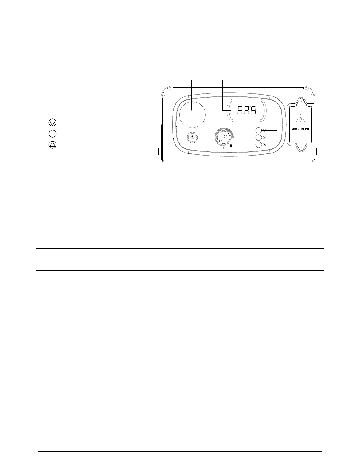
1.1.1 Control panel layout
1. ON/OFF button
2. Central Heating Control knob
3. button
4.
5. button
6. Mains supply terminal board
button
GENERAL INFORMATION
78
ON / OFF
7. Digital LCD display
8. Programmer location (N/A)
Figure 1: Control Panel
1.1.2 Operating the appliance
Operation Instruction
Switching the boiler on
Adjusting the Central Heating temperature
Switching the boiler off
Table 1: Control panel display
Press the ON/OFF button (1)
Turn the Central Heating Control knob (2):
- the temperature setting will appear on the display
Press the ON/OFF button (1)
1 2
3 4 5 6
TR05A140.B1107
3
Page 6

GENERAL INFORMATION
1.2 Topping up the system (Error Code H20)
If the water pressure in the central heating circuit falls below 0.3 bar, the boiler will go to lock out (stop
working) and Error Code H2O will appear on the display. This could be caused be a leak in the system,
if air is bled from a radiator or if a radiator is replaced. The system will then need to be topped up.
To top up the system:
• Let the boiler and radiators cool down;
• Connect the filling loop (usually located near the boiler);
• Open the filling loop valve (or valves);
• Fill the system until the pressure gauge (located on the underside of the boiler) reads 1 bar;
• Switch the boiler off then on again using the ON/OFF button on the Control Panel;
• Check that Error Code H2O is no longer shown on the Control Panel display;
• Close the filling loop valve (or valves) and disconnect the filling loop.
The boiler should now fire and continue to work normally.
If a lot of water was required to fill the system (such as after a radiator is replaced) it may be necessary
to repeat the process a few times over a period.
1.3 If you smell gas
• DO NOT operate any electric switches, telephones or any other equipment that may cause sparks;
• Open doors and windows immediately to create a current of air and ventilate the room;
• Shut off the main gas supply valve (either at the meter or on the cylinder in the case of bottled gas);
• From a safe location, telephone the following 24 hour gas emergency numbers:
Great Britain 0800 111 999
Northern Ireland 0800 002 001
Republic of Ireland 1850 20 50 50
TR05A140.B1107
4
Page 7

GENERAL INFORMATION
2 GENERAL INFORMATION
2.1 General warnings
This appliance must only be installed and commissioned by professionally qualified personnel in
accordance with current laws and standards and in line with the manufacturer’s instructions.
In the United Kingdom, the installation must be carried out by a CORGI Registered Installer. To check for
authorised qualified engineers please contact CORGI on 0870 401 2300. The installation must be carried
out in accordance with the relevant requirements of:
- The Gas Safety Regulations;
- The appropriate Building Regulations – either the Building Regulations, the Building Regulations
(Scotland) or the Building Regulations (Northern Ireland);
- The Water Fittings Regulations or Water Byelaws in Scotland;
- The current I.E.E. Wiring Regulations.
Where no specific instructions are given, reference should be made to the relevant British Standards
Code of Practice.
In the Republic of Ireland, the installation must be carried out by a competent person and in accordance
with the current edition of I.E. 813 ‘Domestic Gas Installations’, the current Building Regulations and the
current ETCI rules for electrical installations.
The appliance must be used solely for the purpose for which it has been designed and manufactured:
central heating and domestic hot water production. Any other use is deemed as improper and as such
dangerous. Under no circumstances will the manufacturer be held responsible for damage or injury to
persons or animals caused by errors in the installation and/or use of the appliance, or through noncompliance with current local and national standards and/or the manufacturer’s instructions.
This instruction manual forms an integral and essential part of the product and must be kept with the
appliance, in a safe place, available for future reference. This manual, along with the Benchmark
commissioning booklet, must be left with the end user as per Regulation 29 of the HSC Gas Safety
(Installation and Use) Regulations 1998.
The warnings contained in this chapter have been written for the appliance user, the installer and the
service engineer.
This instruction manual must be read carefully as it provides information on the operation and the
operating limits of the appliance.
This appliance is only suitable for use in a sealed central heating system.
2.2 Information
• After the removal of all the packaging, check that the appliance has not been damaged. In case of doubt, do not
attempt to use the product but refer to the supplier. Packing materials (cardboard box, wooden crate, nails, staples,
plastic bags, polystyrene, etc.) must not be left within reach of children as these items represent a potential hazard
and must be disposed of in a responsible manner.
• Before carrying out any cleaning or maintenance operations, isolate the appliance from the electricity supply by
switching off at the main switch and/or any other isolating device.
• Do not obstruct the air intake or flue exhaust terminals.
• In the case of a fault and/or malfunction in the appliance, shut down the system. Do not interfere with or attempt to
repair the appliance. Contact your commissioning engineer in the first instance or contact the W armflow Customer
Care Centre on 028 9262 1515.
• Any warranty repairs to the appliance must be carried out exclusively by the manufacturer’s authorised service centre
using original spare parts. Non-compliance with this requirement may compromise the safety of the appliance and
invalidate the warranty. In order to guarantee the efficiency of the appliance and its correct operation, it must be
serviced regularly by professionally qualified personnel in line with the manufacturer’s instructions.
TR05A140.B1107
5
Page 8

GENERAL INFORMATION
• W hen the appliance is no longer required for use, any parts that may constitute potential sources of danger must be
rendered harmless.
• Only original accessories or optional extras (including electrical parts) may be used with the appliance.
• Should there be a smell of gas present in the room where the appliance is installed, DO NOT attempt to activate any
electric switches, telephones or any other equipment that may cause sparks. Open doors and windows immediately to
create a current of air and ventilate the room. Shut-off the main gas supply valve (either at the meter or on the cylinder
in the case of bottled gas), then telephone the following 24 hour gas emergency numbers:
Great Britain 0800 111 999
Northern Ireland 0800 002 001
Republic of Ireland 1850 20 50 50
• Before starting the boiler for the first time, make sure that it is connected to a water supply and central heating system
compatible with its performance characteristics.
• Check the technical data displayed on the packing and on the data plate located on the inside of the front casing.
Also check that the burner is appropriate for the type of gas to be used.
• Make sure that the pipes and fittings used for the gas service are perfectly tight and that there are no gas
leaks.
• Prior to start-up, the central heating pipes should be flushed to remove any residues that could compromise the
operation of the appliance.
• The appliance can be regarded as being electrically safe when it has been connected to an effective earth system
installed in accordance with the requirements of current safety standards. This fundamental safety requirement must
be checked and verified. In case of doubt, have the electrical system checked by a qualified electrician. The
manufacturer will not be held liable for any damage or injury caused as a result of an ineffective or non-existent earth
system.
• The domestic power supply must be checked by a qualified electrician to ensure that it can support the maximum
power absorption of the appliance, as indicated on the appliance data plate (positioned on the inside of the front
casing). In particular, make sure that the cable ratings are adequate for the power absorbed.
• Do not use adapters; multiple sockets or extension leads to connect the appliance to the mains power supply.
• The appliance must be connected to the mains power supply through an appropriate electrical isolator in accordance
with the current wiring regulations.
• W hen using an electrical appliance, a few fundamental rules must be observed:
Do not touch the appliance with damp or wet parts of the body or when barefoot;
Do not pull on the electric wires;
Do not leave the appliance exposed to atmospheric elements (rain, sun, etc,) unless these conditions have been
expressly provided for;
Do not allow the appliance to be used by children or anyone unfamiliar with its operation.
• The user must not replace the power supply cable.
• If the cable is damaged in any way, switch off the appliance and have the cable replaced by a suitably qualified
electrician.
• When the appliance is no longer required for use, switch off the main power supply to deactivate all the
electrical components (circulating pump, burner, etc.)
TR05A140.B1107
6
Page 9

GENERAL INFORMATION
2.3 Product conformity
Warmflow declares that all its products are manufactured to a high specification and in compliance with the relevant
standards.
All Warmflow gas boilers are CE certified and possess technical and functional characteristics that comply with the
following directives and standards:
GAS APPLIANCES DIRECTIVE 90/396 CEE for CE compliance
LOW VOLTAGE DIRECTIVE 73/23 CEE
ELECTROMAGNETIC COMPATIBILITY DIRECTIVE 89/336 CEE
BOILER EFFICIENCY DIRECTIVE 92/42 CEE
UNI EN 297 for GAS-FIRED CENTRAL HEATING BOILERS TYPE B OF NOMINAL HEAT INPUT ≤ 70 kW
EN 483 for GAS-FIRED CENTRAL HEATING BOILERS TYPE C OF NOMINAL HEAT INPUT ≤ 70 kW
UNI EN 677 for GAS-FIRED CENTRAL HEATING BOILERS: SPECIFIC REQUIREMENTS FOR CONDENSING
BOILERS WITH NOMINAL HEAT INPUT ≤ 70 kW
Warmflow will not be responsible for the consequences of non-observance of the instructions contained
within this manual where actions not specifically described herein are undertaken.
TR05A140.B1107
7
Page 10
TECHNICAL CHARACTERISTCS
3 TECHNICAL CHARACTERISTICS
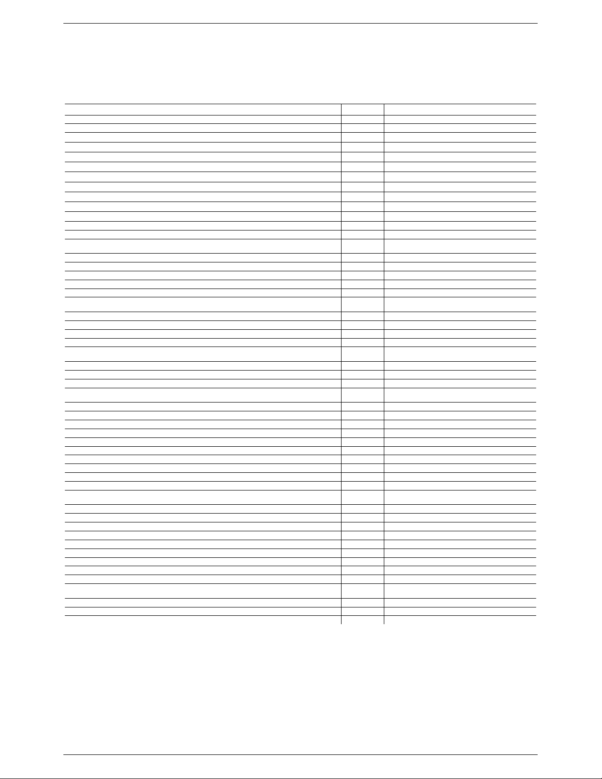
3.1 Technical data
Model
Appliance Type C13, C33, C43, C53, C63, C83
Appliance Category II2H3+
Heat Input max
Heat Input min
Heat Output max (50/30°) kW 26.67
Efficiency 100% (full load 50/30°) % 106.7
Efficiency 30% (partial load 50/30°) % 106.3
Heat Output max - 80/60°C (Non condensing) kW 24.6
Heat Output min - 80/60°C (Non condensing) kW 8.73
Efficiency 100% (full load 80/60°) % 98.4
Efficiency 30% (partial load 80/60°) % 100.1
GAS DIRECTIVE 92/42/ECC - Efficiency marking stars 4
SEDBUK band A
Central Heating (CH) Circuit
CH water temperature setting (min-max) °C 30-80
Max. CH working temperature °C 80
Expansion vessel capacity litres 8
Max. CH working pressure bar 2.5
Min. CH working pressure bar 0.3
Dimensions
Width mm 410
Height mm 730
Depth mm 285
Weight (net) kg 46
Hydraulic Connections
CH Flow connection Ø 3/4" (22mm tail supplied)
CH Return connection Ø 3/4” (22mm tail supplied)
Gas connection Ø 3/4” (22mm tail supplied)
Flue Systems
Horizontal Concentric flue system Ø mm 60/100
Max. Flue length m 5
Horizontal Concentric flue system Ø mm 80/125
Max. Flue length m 7
Vertical Concentric flue system Ø mm 60/100
Max. Flue length m 5
Vertical Concentric flue system Ø mm 80/125
Max. Flue length m 7
Twin Pipe flue system Ø mm 80/80
Max. Flue length m 50
Gas Supply
Natural gas (Methane) G20
Inlet pressure mbar 20
Gas consumption m3/h 2.65
Butane G30
Inlet pressure mbar 30
Gas consumption kg/h 1.97
Propane G31
Inlet pressure mbar 37
Gas consumption kg/h 1.94
Electrical Specifications
Power supply V/Hz 230/50
Electrical power consumption W 170
Electrical protection IP X4D
kW 25
kW 9
GS25A
Table 2: Technical data
TR05A140.B1107
8
Page 11
730
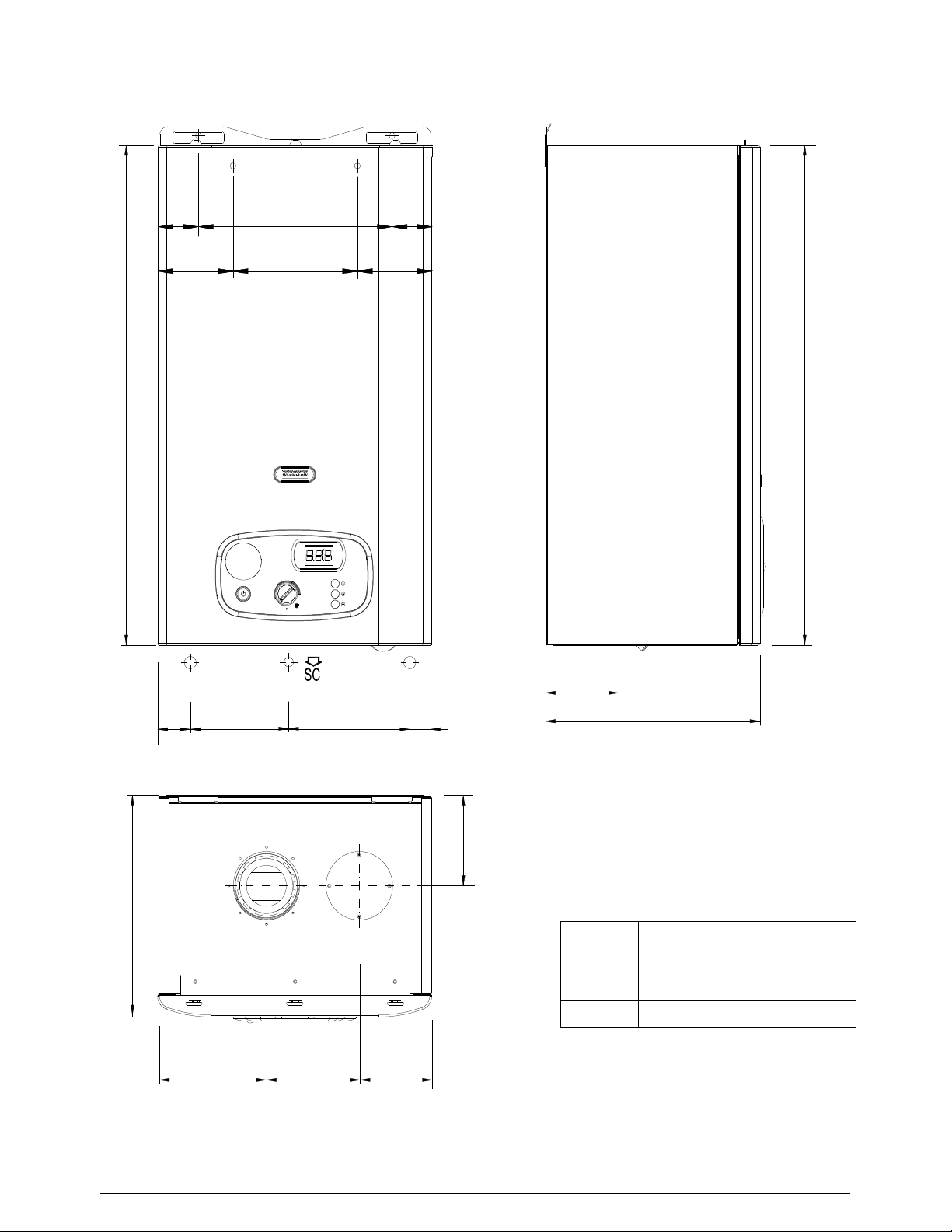
3.2 Dimensions
48.5 313 48.5
TECHNICAL CHARACTERISTCS
111.5187111.5
730
ON / OFF
HR
G
HF
14849 182 31
105
285
132
285
LEGEND
HR HEATING RETURN 22mm
HF HEATING FLOW 22mm
G
SC CONDENSATE DRAIN 25mm
GAS 22mm
110137163
Figure 2: Dimensions
TR05A140.B1107
9
Page 12
25
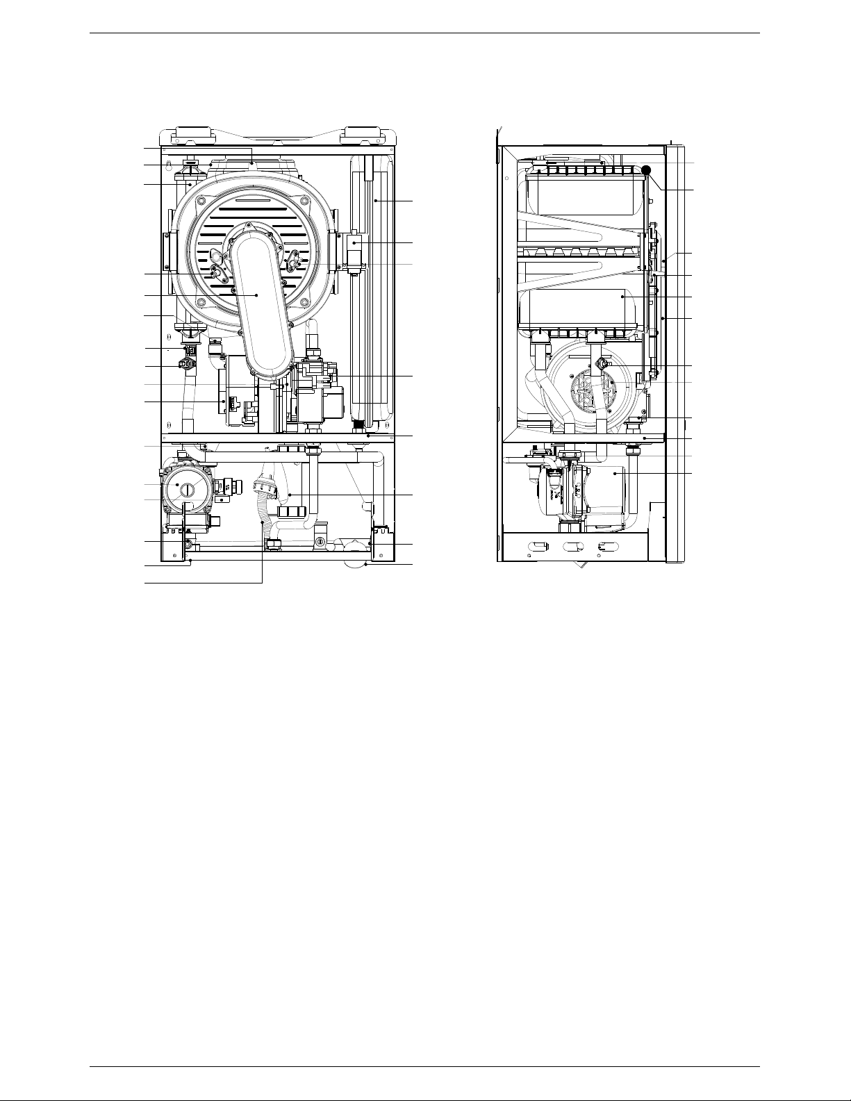
3.3 Internal components
TECHNICAL CHARACTERISTCS
17
16
13
12
11
14
10
22
24
23
16
1
18
8
4
5
2
3
7
9
4
5
1
2
12
6
6
9
19
19
11
14
20
15
21
Figure 3: Internal components
LEGEND
1. PRIMARY CONDENSING HEAT EXCHANGER
2. PREMIX BURNER UNIT (GAS MANIFOLD + BURNER)
3. HEAT EXCHANGER CONDENSATE DRAIN CONNECTION
4. IONISATION ELECTRODE
5. IGNITION ELECTRODE
6. FAN
7. VENTURI
8. IGNITION TRANSFORMER
9. ELECTRONIC GAS VALVE
10. 3 BAR PRESSURE RELIEF VALVE – HEATING CIRCUIT
11. AUTOMATIC AIR VENT VALVE
12. HEATING SAFETY THERMOSTAT
13. HEATING SENSOR
14. PUMP WITH AIR VENT
15. WATER PRESSURE SWITCH
16. FLUE HOOD
17. FLUE SAFETY THERMOFUSE
18. EXPANSION VESSEL
19. ROOM SEALED CHAMBER BULKHEAD
20. CONDENSATE TRAP
21. WATER PRESSURE GAUGE
22. SYSTEM DRAIN VALVE
23. CONDENSATE DRAIN PIPE
24. AUTOMATIC BYPASS
25. PRIMARY HEAT EXCHANGER MANUAL AIR VENT VALVE
TR05A140.B1107
10
Page 13
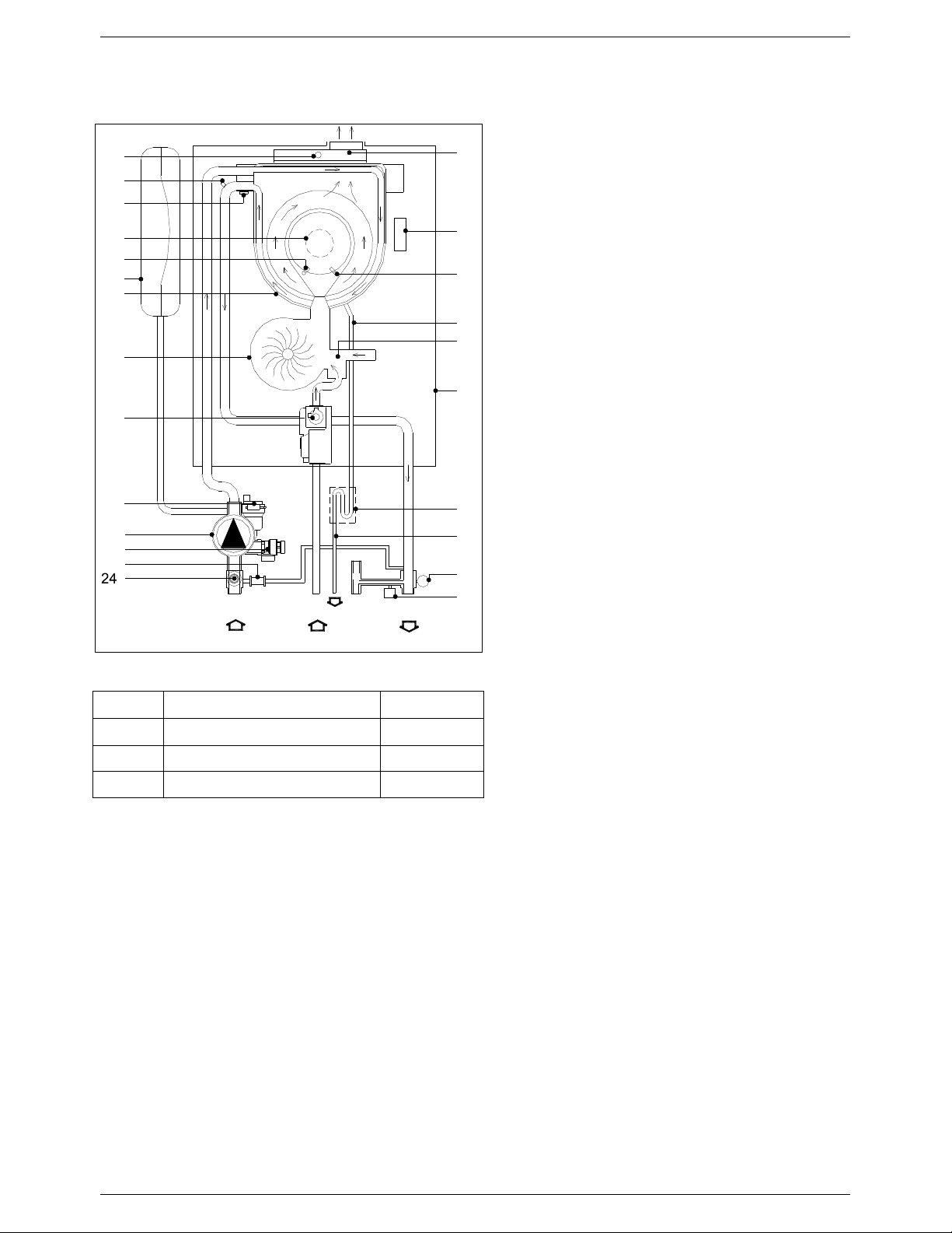
3.4 Function diagram
17
13
12
2
4
18
1
6
9
11
14
10
22
TECHNICAL CHARACTERISTCS
LEGEND
16
8
5
3
7
19
20
23
21
15
SC
G HFHR
1. PRIMARY CONDENSING HEAT EXCHANGER
2. PREMIX BURNER UNIT (GAS MANIFOLD &
BURNER)
3. HEAT EXCHANGER CONDENSATE DRAIN PIPE
4. IONISATION ELECTRODE
5. IGNITION ELECTRODE
6. FAN
7. VENTURI
8. IGNITION TRANSFORMER
9. ELECTRONIC GAS VALVE
10. 3 BAR PRESSURE RELIEF VALVE - HEATING
CIRCUIT
11. AUTOMATIC AIR VENT VALVE
12. HEATING SAFETY THERMOSTAT
13. HEATING SENSOR
14. PUMP WITH AIR VENT
15. WATER PRESSURE SWITCH
16. FLUE HOOD
17. FLUE SAFETY THERMOFUSE
18. EXPANSION VESSEL
19. ROOM SEALED CHAMBER
20. CONDENSATE TRAP
21. WATER PRESSURE GAUGE
22. AUTOMATIC BYPASS
23. CONDENSATE DRAIN PIPE
24. SYSTEM DRAIN VALVE
Figure 4: Function diagram
HR HEATING RETURN 22mm
HF HEATING FLOW 22mm
G
SC
GAS 22mm
CONDENSATE DRAIN 25mm
TR05A140.B1107
11
Page 14
TECHNICAL CHARACTERISTCS
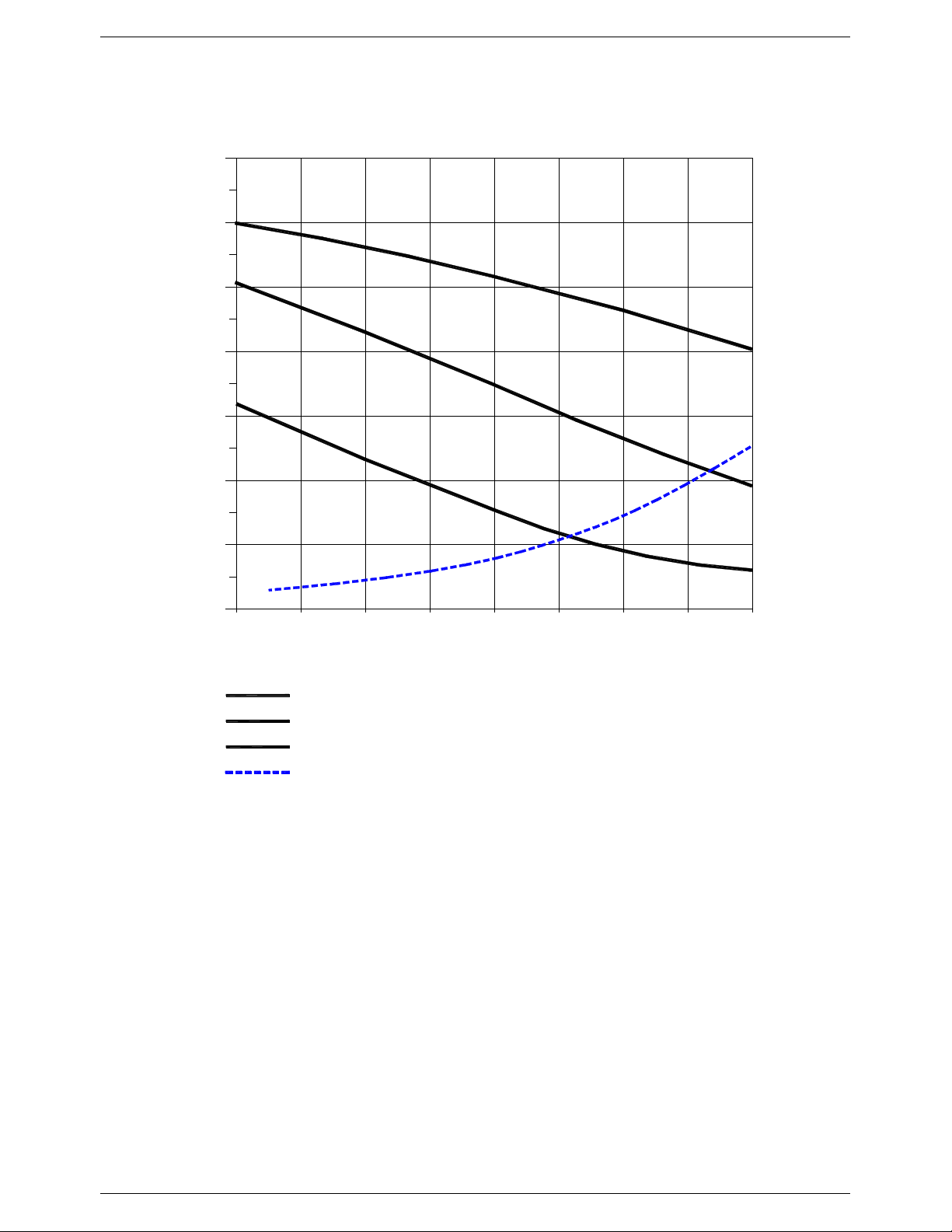
3.5 Circulation pump performance curves
70
60
Head (kPa)
50
40
30
I
20
III
II
10
0
0
III
II
I
200
Available head at maximum speed
Available head at second speed
Available head at minimum speed
Appliance Loss
Figure 5: Pump performance curves
800400 600
1000
14001200 1600
Flow l/h
TR05A140.B1107
12
Page 15
TECHNICAL CHARACTERISTCS
S
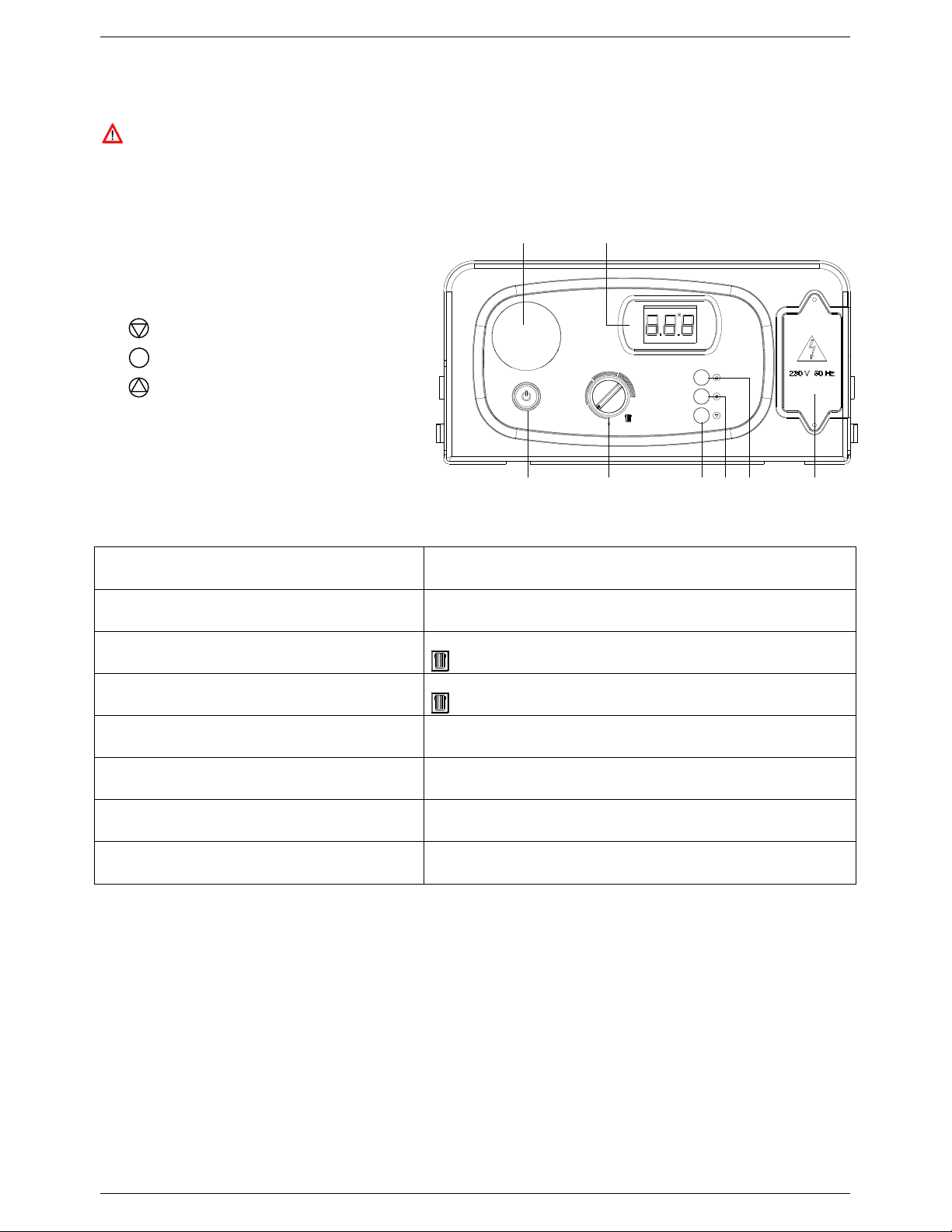
3.6 Control panel and display
The appliance MUST be supplied with a permanent live in order for the boiler’s protective functions to
operate. These functions include frost protection, post-ventilation, pump overrun and pump & 3-way
valve inactivity protection. On first connection to the power supply, the appliance must be switched on
using the ON/OFF button on the control panel to activate all of the above protective features. The
appliance can then be switched off but the protective features will remain active.
3.6.1 Layout
1. ON/OFF button
2. CH Control knob
3. DISPLAY button
4.
SERVICE button
5. MODE button
6. Mains supply terminal board
7. Digital LCD display
8. Programmer location (N/A)
3.6.2 Boiler operation
ON / OFF
1 2
Figure 6: Control Panel
78
3 4 5 6
Mode / Control Input Display will show:
Boiler switched off
Press ON/OFF button (to switch the boiler on)
CH controls call for heat
CH Control knob turned
SERVICE button pressed & held for 7 seconds
Boiler protection function activated
(automatically)
Boiler locked out
Table 3: Control panel display
OFF
Primary circuit temperature in ºC
Icon – lit when appliance switched on
Primary circuit temperature in ºC
Icon – flashes whilst CH mode is active
CH set point temperature in ºC – displayed for 3 seconds
Function Code 07 – flashes whilst activated
(see Section 3.6.3)
Function Code 08 – flashes whilst activated
(see Section 3.6.3)
Error Code – flashes whilst locked out
(see Section 6.8.1)
TR05A140.B1107
13
Page 16
TECHNICAL CHARACTERISTCS
S
3.6.3 Function codes
Code Function Description
Operates the boiler at maximum CH output for 15 minutes
07 Commissioning Mode
08
CH Frost Protection Mode
Table 4: Function codes
without modulation.
Activated by pressing and holding the
Deactivated by switching the appliance off.
Operates the boiler at minimum CH output in Heating Only
Mode.
Activated when the CH sensor detects below 5°C.
Deactivated when the CH sensor detects above 30°C.
button for 7 seconds.
TR05A140.B1107
14
Page 17

INSTALLATION INSTRUCTIONS
4 INSTALLATION
4.1 Reference standards
In the United Kingdom, the installation of this appliance must be carried out by a CORGI Registered
Installer. To check for authorised qualified engineers contact CORGI on 0870 401 2300. The installation
must be carried out in accordance with the relevant requirements of the:
- Gas Safety Regulations;
- The appropriate Building Regulations – either the Building Regulation, the Building Regulations
(Scotland) or the Building Regulations (Northern Ireland);
- The Water Fittings Regulations or Water Byelaws in Scotland;
- The current I.E.E. Wiring Regulations.
Where no specific instructions are given, reference should be made to the relevant British Standards
Code of Practice.
In the United Kingdom, the following Codes of Practice apply:
BS 5440: Part 1 Flues
BS 5440: Part 2 Air Supply
BS 5546 Installation of hot water supplies for domestic purposes
BS 5449 Forced circulation hot water systems
BS 6700 Installation of cold water supplies for domestic purposes
BS 6798 Installation of gas-fired hot water boilers
BS 6891 Gas Installation
BS 7074 Expansion Vessels and ancillary equipment for sealed water systems
BS 7593 Treatment of water in domestic hot water central heating systems
BS 7671 IEE wiring regulations
In the Republic of Ireland, the installation must be carried out by a competent person and in accordance with the
current edition of I.E. 813 ‘Domestic Gas Installations’, the current Building Regulations and the current ETCI
rules for electrical installations.
Failure to install a gas appliance correctly and in accordance with the above standards could result in
prosecution.
TR05A140.B1107
15
Page 18

INSTALLATION INSTRUCTIONS
4.2 Unpacking
■ The materials (cardboard) used for packing the appliance are fully recyclable.
■ It is recommended that the packing material is only removed when the appliance is ready to be installed.
The manufacturer will not be held responsible for damage caused by incorrect storage of the product.
■ Packing materials (plastic bags, polystyrene, nails, etc.) must not be left within reach of children, in that
these items represent a potential hazard.
A. With the packed appliance on
the floor (see Figure 7), remove
the staples and open out the four
flaps on the end of the box;
B. Stand the boiler up on its end
as shown, supporting it from
underneath;
C. Lift off the box and remove all
packaging.
STORAGE & HANDLING
Please note that prior to
installation, the boiler should be
stored in the horizontal position
with no more than 5 boilers to a
stack;
Ensure that the boilers are stored
in dry conditions and be aware
that the carton is a two-man lift.
A
C
B
Figure 7: Unpacking instructions
TR05A140.B1107
16
Page 19
4.3 Installing the boiler
INSTALLATION INSTRUCTIONS
■ The appliance must only be
installed on a flat vertical solid wall
capable of supporting its weight.
■ The boiler should be fitted within the
building unless otherwise protected by
a suitable enclosure i.e. garage or
outhouse.
■ If the boiler is sited in an unheated
enclosure, a permanent live supply
must be provided in order for the frost
protection function to operate. The
appliance can still be switched off
using the ON/OFF button on the
control panel.
■ If the boiler is installed in a room
containing a bath or shower, it must
have a room sealed flue and reference
must be made to the relevant
requirements.
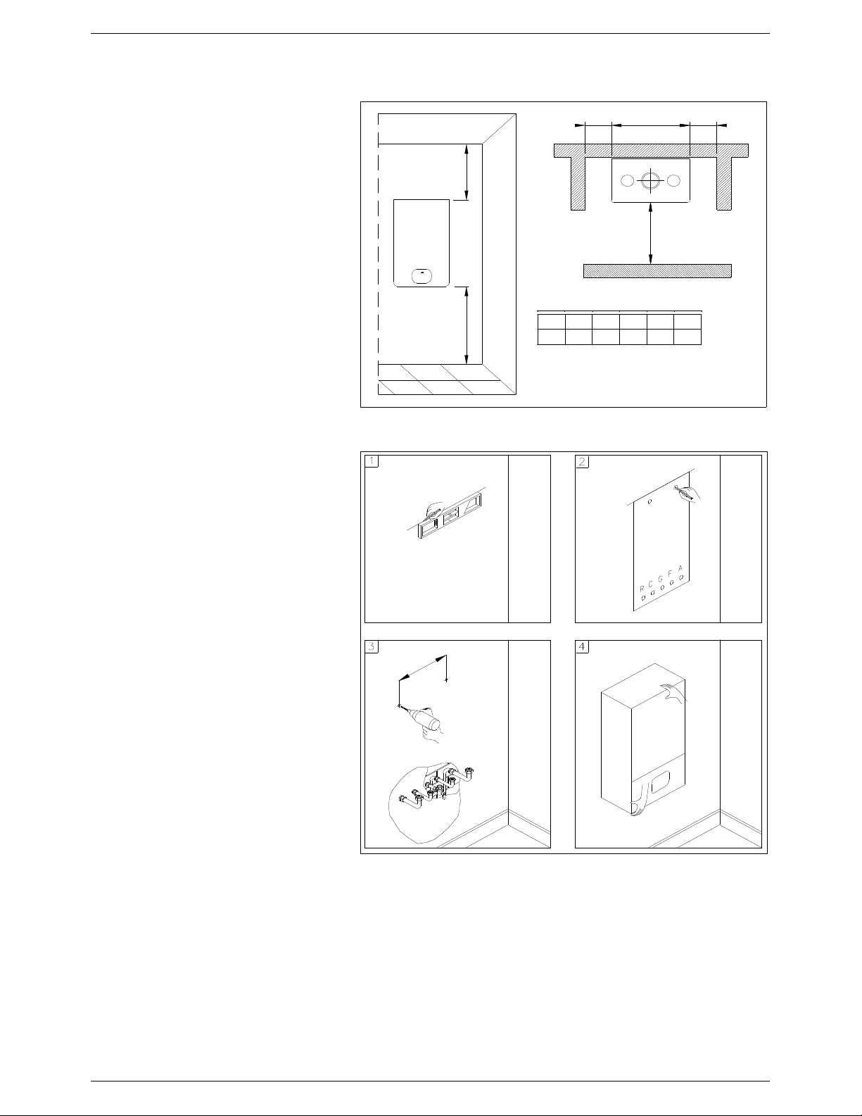
In order to allow access to the interior of
the boiler for maintenance purposes, it is
important that the necessary clearances
indicated in Figure 8 are respected.
For ease of installation, the boiler is
supplied with a template to enable the pipe
connections to be positioned prior to fixing
the appliance to the wall.
To install the boiler, proceed as follows
(see Figure 9):
1 Use a spirit level to mark a horizontal
line on the wall where the boiler is to be
fitted.
2 Position the top of the template along
the line. Mark the centres of fixing
locations and the positions of the water
and gas pipes.
3 Remove the template and install the
gas supply pipe and the central heating
pipes using the fittings supplied with the
boiler.
4 Install the hanging bracket then fix the
boiler to the wall and connect the pipes.
A
B
Figure 8: Access clearances
X
L
H
MI NIMU M DIST ANCE I N mm
X Y L H
Mo de l
X Y L H
RK R 29
X Y L H
10 0045 06060
10 0041 0606 0
A B
A B
200 30 0
10 0041 06060
20 0 30 0
Y
A B
20 0 30 0
Figure 9: Mounting procedure
4.3.1 Compartment ventilation
Where the appliance is installed in a compartment, no air vents are required.
BS 5440: Part 2 refers to room sealed appliances installed in compartments. The appliance will run sufficiently cool
without ventilation.
TR05A140.B1107
17
Page 20
INSTALLATION INSTRUCTIONS
105
Figure
10
: Location of connections
22
4.4 Water connections
In order to comply with the Terms &
Conditions of warranty, the system
must be hot-flushed to remove any
impurities (especially oil and grease)
from the pipes and radiators.
The CH pipes must be adequately
earthed. However, the appliance must
also be provided with an adequate
earth. Pipe work is NOT suitable for this
purpose.
Isolation valves must be installed on
the CH circuit in order to facilitate all
maintenance and service operations
where the boiler needs to be drained.
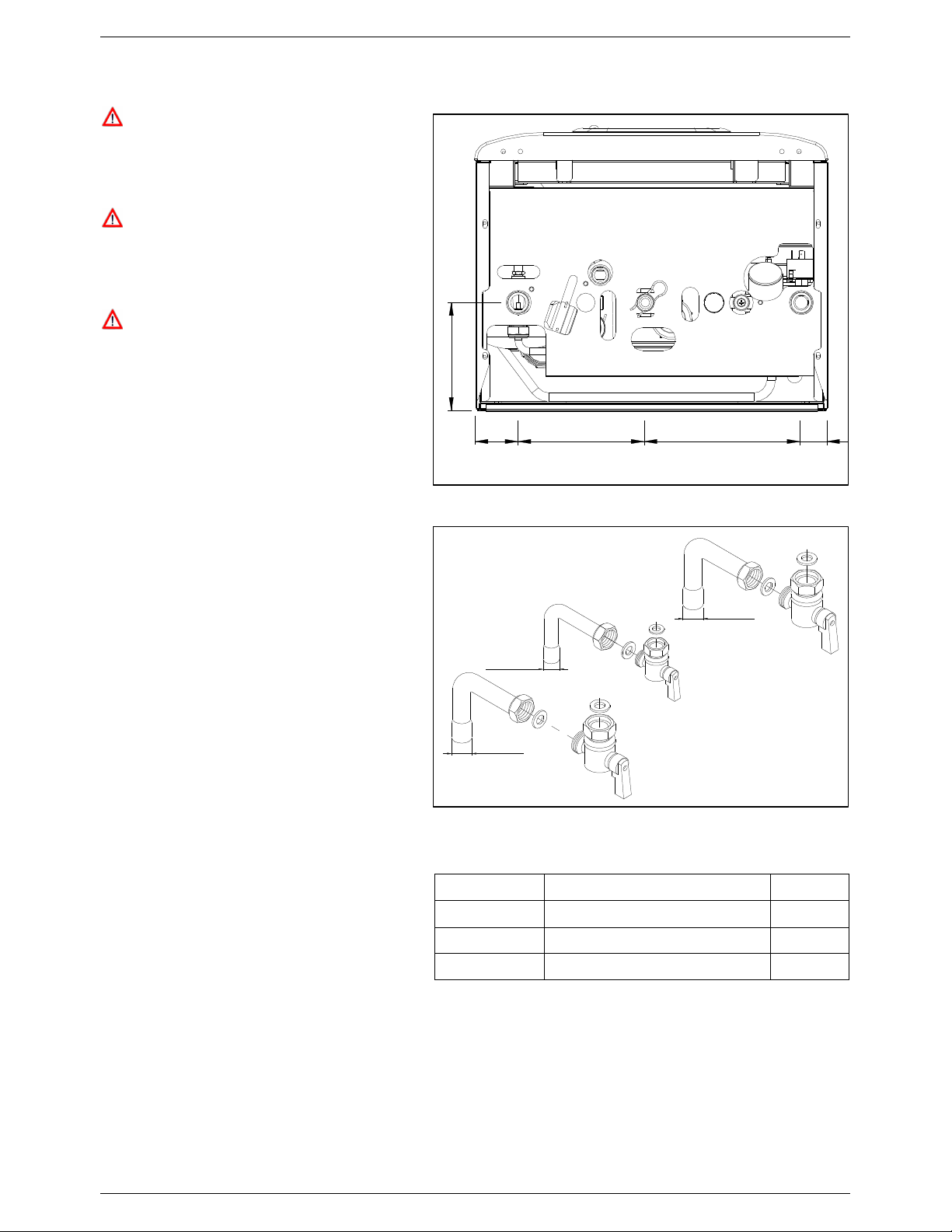
The boiler is supplied with a fittings kit
(see Figure 11) complete with isolation
valves and copper tails.
■ To prevent vibration and noise coming from
the system, do not use pipes of reduced
diameter, short radius elbows or severe
restrictions.
14849 182 31
HR G HF
Ø 22 mm
HF
Ø 15 mm
G
Ø 22 mm
HR
Figure 11: Fittings kit
LEGEND
HR HEATING RETURN 22mm
HF HEATING FLOW 22mm
G
CD
GAS 22mm
CONDENSATE DRAIN 25mm
TR05A140.B1107
18
Page 21
INSTALLATION INSTRUCTIONS
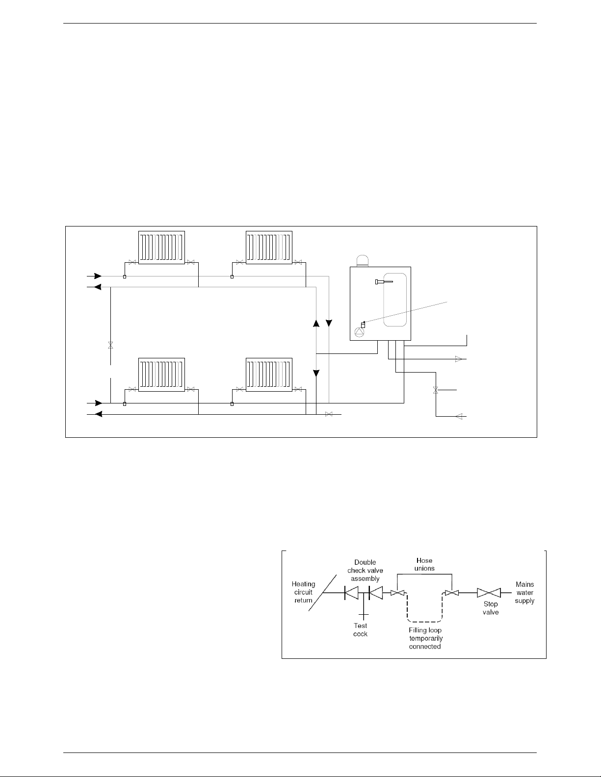
4.4.1 Central heating circuit
The boiler is designed for use in a sealed central heating system in accordance with the requirements of BS 5449 and BS 6798.
The system should be designed to operate with flow temperatures of up to 82°C. When designing the system, the pump
head, expansion vessel size, mean radiator temperature, etc. must all be taken into account.
The boiler is supplied with the following components built in:Pressure relief valve – complies with BS 6759 and set is to operate at 3 bar. The outlet connection of the pressure
relief valve must be connected via a tundish to a safe visible discharge. The manufacturer will not be held
responsible for flooding caused by the operation of the pressure relief valve in the case of system overpressure
where adequate drainage has not been provided.
Pressure gauge – indicates the system pressure.
Expansion vessel – conforms to BS 7074:1 and has a volume of 8 litres. If the total system volume requires more than 8
litres of expansion capacity, an additional expansion vessel will be required.
Bypass – incorporated within the boiler. However, where all radiators are fitted with thermostatic radiator valves, it is
recommended an additional automatic system bypass is fitted.
Lockshield valve
Note: A drain tap should be in stalled at the lowest point of the
heating circuit and beneath the ap pliance
Radiator
valve
Boiler
Heating return
System
drain tap
Automatic air vent
Filling point (see fig. 2)
DHW outlet
Pressure reducing
valve reccomended
for inlet supplies in
excess pf 3.5 bar
Mains water
inlet
Figure 12: Central heating system layout
4.4.2 Filling the central heating system
All fittings used in filling the system must be suitable for mains pressure applications. Filling of the system must be carried out
in an approved manner (in the UK, refer to Guidance G24.2 and Recommendation R24.2 of the Water Regulation Guide) and
in accordance with the instructions in Section 5.2.
The system should be filled via a temporary filling loop connection as shown in Figure 13. After filling, the flexible hose of the
filling loop must be disconnected. The filling loop should be installed such that it can be easily reconnected in order to top up
the system if any water is lost (e.g. due to leakage or
after replacing a radiator).
Drain cocks (to BS 2879) must be fitted to the lowest
points in the system to allow it to be completely drained.
A corrosion inhibitor must be added to the CH circuit in
order to guarantee the life of the appliance. In hard
water areas, a combined corrosion inhibitor and
softener must be used.
The system pre-charge pressure (cold) should be 1
bar.
Figure 13: Filling loop layout
TR05A140.B1107
19
Page 22
Figure
14
: Condensate drain configuration
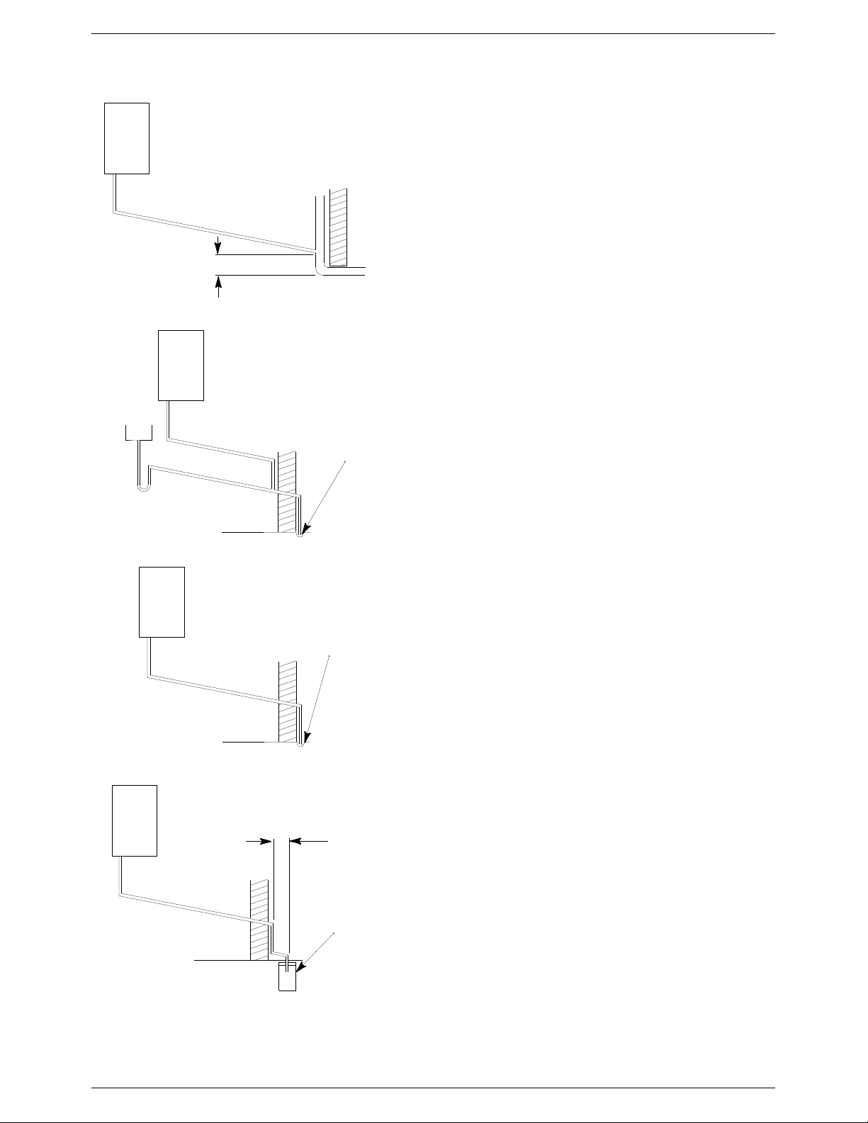
4.5 Condensate drain
INSTALLATION INSTRUCTIONS
Sink
Boiler
2
.
5
Termination to an internal soil and vent pipe
5
0
m
m
p
e
r
m
e
t
r
e
°
M
i
n
i
m
u
m
Boiler
5
2
.
f
a
l
l
450mm min
0
m
m
p
5
°
M
i
n
i
m
o
f
p
i
p
e
r
u
n
External termination via internal discharge
branch e.g. sink waste - downstream
e
r
m
e
t
r
e
o
f
p
i
p
e
r
u
m
f
a
u
l
l
Pipe must terminate above
water level but below
n
surrounding surface
Failure to install the condensate discharge pipe work
correctly will affect the reliable operation of the boiler.
The condensate discharge pipe must not rise at any
point along its length. There must be a fall of at least
2.5° (50mm per metre) along the entire run.
The boiler condensate trap is fitted with a 1 metre
length of 25mm flexible pipe which should generally
discharge internally into the household drainage
system. If this is not possible, discharge into an outside
drain is acceptable.
Ensure the discharge of condensate complies with any
national or local regulations in force.
The discharge pipe should be run in a proprietary
plastic drain pipe material. Metal pipe work is NOT
suitable for use in condensate discharge systems.
The pipe should be a minimum of 21.5 mm diameter
and must be supported using suitably spaced clips to
prevent sagging. To reduce the risk of condensate
being trapped, as few bends and fittings as possible
should be used.
Boiler
5
0
2
.
External termination to a drain or gully
Boiler
Pipe must terminate above
water level but below
surrounding surface
5
0
m
m
p
e
r
m
e
t
r
e
o
f
p
i
2
.
5
°
M
i
n
i
m
u
External termination to a purpose made soak-away
m
m
p
e
r
m
e
t
r
e
o
5
°
M
i
n
f
i
m
u
m
f
a
l
l
p
e
r
u
m
f
a
p
i
p
e
n
l
l
r
u
n
Holes in the soak-away must
face away from the building
Any condensate discharge pipe work external to the
building (or in an unheated area, e.g. garage) must be
insulated to protect against frost. It is also
recommended that the pipe diameter is increased to
32mm. Any pipe run external to the building must not
exceed 3 metres in length.
If the boiler is fitted in an unheated location the entire
condensate discharge pipe should be treated as an
external run.
When discharging condensate into a soil stack or waste
pipe the effects of existing plumbing must be
considered. If soil pipes or waste pipes are subjected to
internal pressure fluctuations when WCs are flushed or
sinks emptied then back pressure may force water out
of the boiler trap and cause appliance lockout.
500mm min
TR05A140.B1107
20
Page 23

INSTALLATION INSTRUCTIONS
4.6 Gas connection
The connection to the gas supply must be carried out by professionally qualified personnel in
accordance with relevant standards.
When connecting the boiler to the gas supply pipe, only use appropriate washers and gas fittings. The
use of hemp, PTFE tape and similar materials is not allowed.
In areas prone to Copper Sulphide build-up in gas supply pipes (such as in Northern Ireland) an in-line
filter should be installed upstream of the appliance.
Before installing the boiler, check that:
■ The pipe work is appropriately sized for the flow rates required and the pipe lengths installed, and must be fitted
with all the safety and control devices required by current standards;
■ The gas supply line must be a minimum of a 22 mm diameter pipe with a direct supply from meter to boiler and
comply with current standards and regulations;
■ Check the internal and external seals of the gas supply system;
■ A gas shut-off valve must be installed upstream of the appliance;
■ An in-line filter is installed, where necessary, and is free from blockage;
■ Before starting up the boiler, make sure that the type of gas corresponds to that for which the appliance has
been configured (see gas type label inside the boiler). Conversion of the appliance from natural gas to LPG must
only be carried out by qualified personnel;
■ Check that the gas supply pressure is between the values stated on the rating plate (see gas type label inside
the boiler);
■ Prior to installation, it is good practice to ensure that there are no machining residues on the gas supply pipe.
TR05A140.B1107
21
Page 24

INSTALLATION INSTRUCTIONS
4.7 Electrical connections
4.7.1 General warnings
The connection to the mains power supply must be carried out by professionally qualified personnel,
registered in accordance with current legislation.
Always check to make sure that the appliance has an effective earth system. This requirement is only
satisfied if it has been properly connected to an effective earth system installed in accordance with the
requirements of current safety standards. This basic safety measure must be connected, checked and
verified by professionally qualified personnel. In case of doubt, have the electrical system checked by
a qualified electrician. The manufacturer will not be held liable for any damage or injury caused as a
result of an ineffective earth system.
■ The boiler is designed to operate with a 230 V, 50 Hz supply. The connection to the mains electricity supply must
be via a fused spur and the appliance must be protected by a 3A fuse. Make sure that the positions of the live
and neutral wires correspond to the wiring diagram (Figure 15);
■ Ensure the domestic power supply is checked by a qualified electrician to ensure that it can support the
maximum power absorption of the appliance, as indicated on the rating plate. In particular, make sure that the
cable sizes are adequate for the power absorbed by the appliance;
When using an electrical appliance, a few fundamental rules must be observed:
• Do not touch the appliance with damp or wet parts of the body or when barefoot;
• Do not pull on the electric wires;
• Do not leave the appliance exposed to atmospheric elements (rain, sun, etc,) unless these conditions have
been expressly provided for;
• Do not allow the appliance to be used by children or anyone unfamiliar with its operation.
TR05A140.B1107
22
Page 25
INSTALLATION INSTRUCTIONS
4.7.2 Power supply
The connection to the mains power supply must be carried out by professionally qualified personnel,
registered in accordance with current legislation.
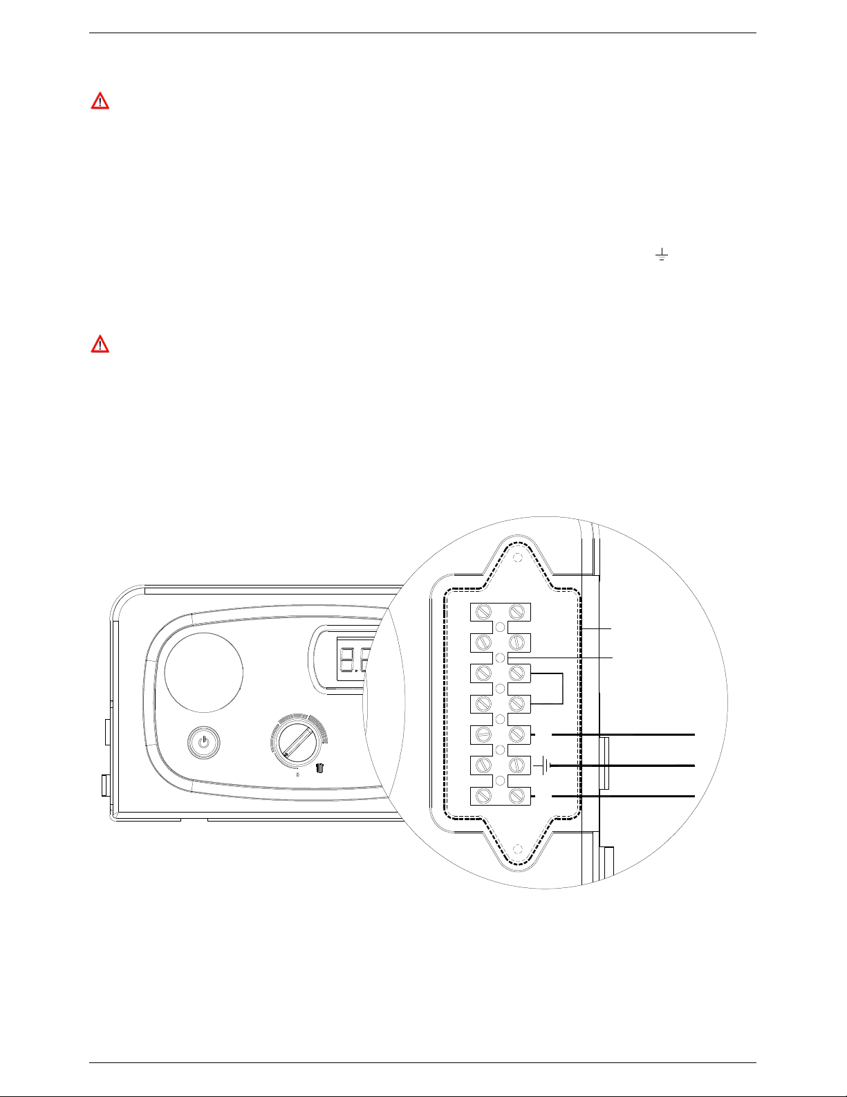
Connect the power supply to the terminal board inside the control panel as follows:
a. Ensure the supply is isolated;
b. Remove the front casing panel of the boiler (refer to Section 6.3 for guidance);
c. Remove terminal block cover A (see Figure 15);
d. Connect the wires to terminal block B as follows (see Figure 15);
• Connect the earth wire (coloured green/yellow) to the terminal marked with the earth symbol “ “;
• Connect the neutral wire (coloured blue) to the terminal marked with the letter “ N ”;
• Connect the permanent live wire (coloured brown) to the terminal marked with the letter “ L ”;
e. Replace terminal block cover A.
The appliance MUST be supplied with a permanent live in order for the boiler’s protective functions to
operate correctly. These functions include frost protection, post-ventilation, pump overrun and pump
& 3-way valve inactivity protection. On first connection to the power supply, the appliance must be
switched on using the ON/OFF button on the control panel to activate all of the above protective
features. The appliance can then be switched off but the protective features will remain active.
The terminals marked Ta and Se are for external zero-voltage controls including room thermostats, time clocks,
zoned system controls and weather compensating controls. Connection of these controls is covered in Section 7.
SeSeTaNL
A
B
Ta
blue
ON / OFF
green/yellow
brown
Figure 15: Power supply connections
TR05A140.B1107
23
Page 26
INSTALLATION INSTRUCTIONS
4.8 Flue connections
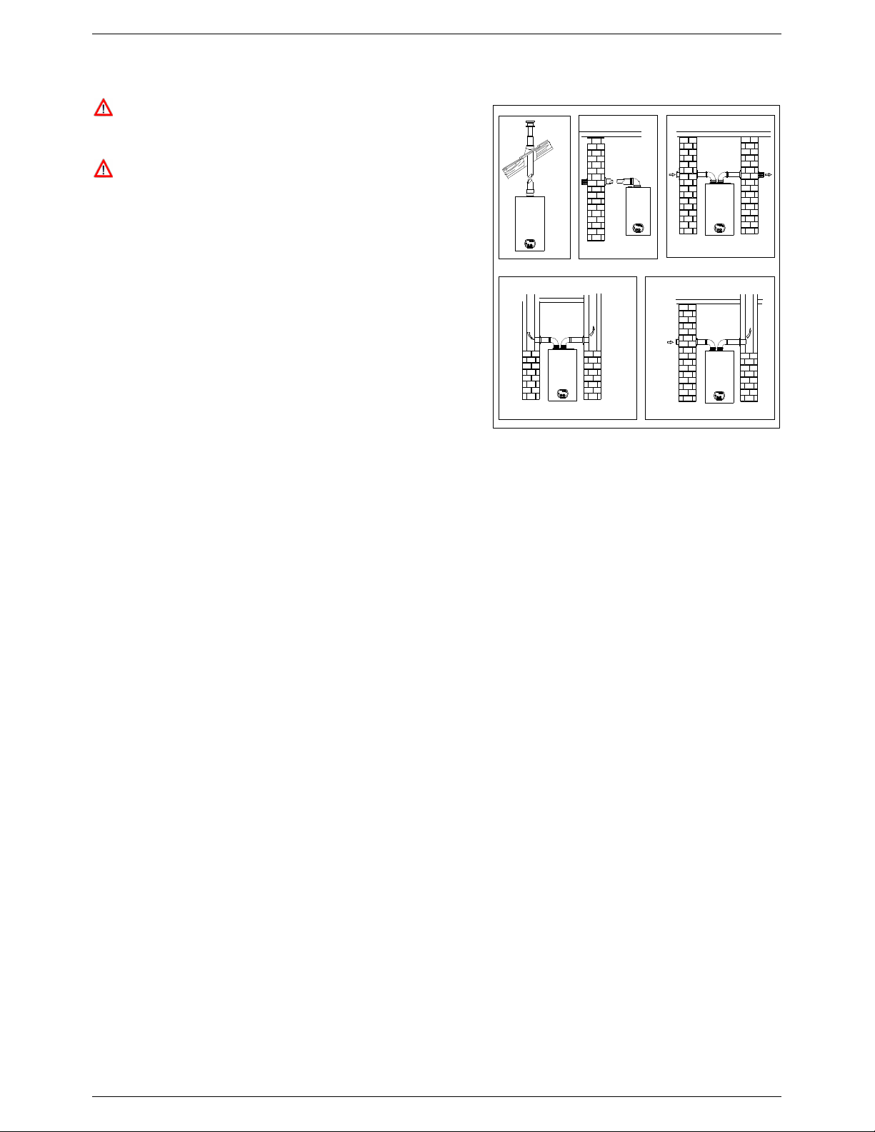
In order to ensure that the appliance functions correctly
and efficiently, only Warmflow-approved flue
components may be used with this appliance.
Traditional flue components cannot be used for
conveying exhaust fumes from condensing boilers.
Coaxial Balanced Flues
Where a horizontal balanced flue system is installed, the flue
must be positioned level, not sloping upwards or downwards.
0.5
40ON50
60708 0
0.5
40ON50
60708 0
C33
C13
0.5
80706 0
50ON40
C53
The exhaust duct and air intake ducts have been designed so as
to minimise the build-up of condensate in the flue and protect
against the effect of the weather or the ingress of foreign bodies.
Twin Pipe Flues
For the exhaust discharge duct of a twin pipe system, the entire
length of the duct must slope upwards towards the exterior in
order to facilitate the flow of condensate back to the combustion
chamber, which has been specifically designed to collect and
drain the acidic condensate;
For the air intake duct of a twin pipe system, the entire length of
50ON40
C43 C83
Figure 16: Appliance and flue types
0.5
40ON50
60708 0
0.5
80706 0
the duct must slope downwards towards the exterior to prevent
the entry of rainwater, dust or foreign bodies.
Reference Information – Type C Appliances
Exhaust flues for gas-fired appliances are classified at European level according to the method used for drawing
combustion air to and discharging exhaust fumes from the appliance. This classification applies to gas-fired
appliances in general.
The combustion circuit (air intake, combustion chamber, heat exchanger and fumes exhaust discharge) of Type C
Appliances is sealed off from the room in which the appliance is installed, i.e. room sealed. The combustion air
intake and the fumes exhaust discharge are connected directly to the outside.
TR05A140.B1107
24
Page 27
INSTALLATION INSTRUCTIONS
300 min
4.8.1 Flue position
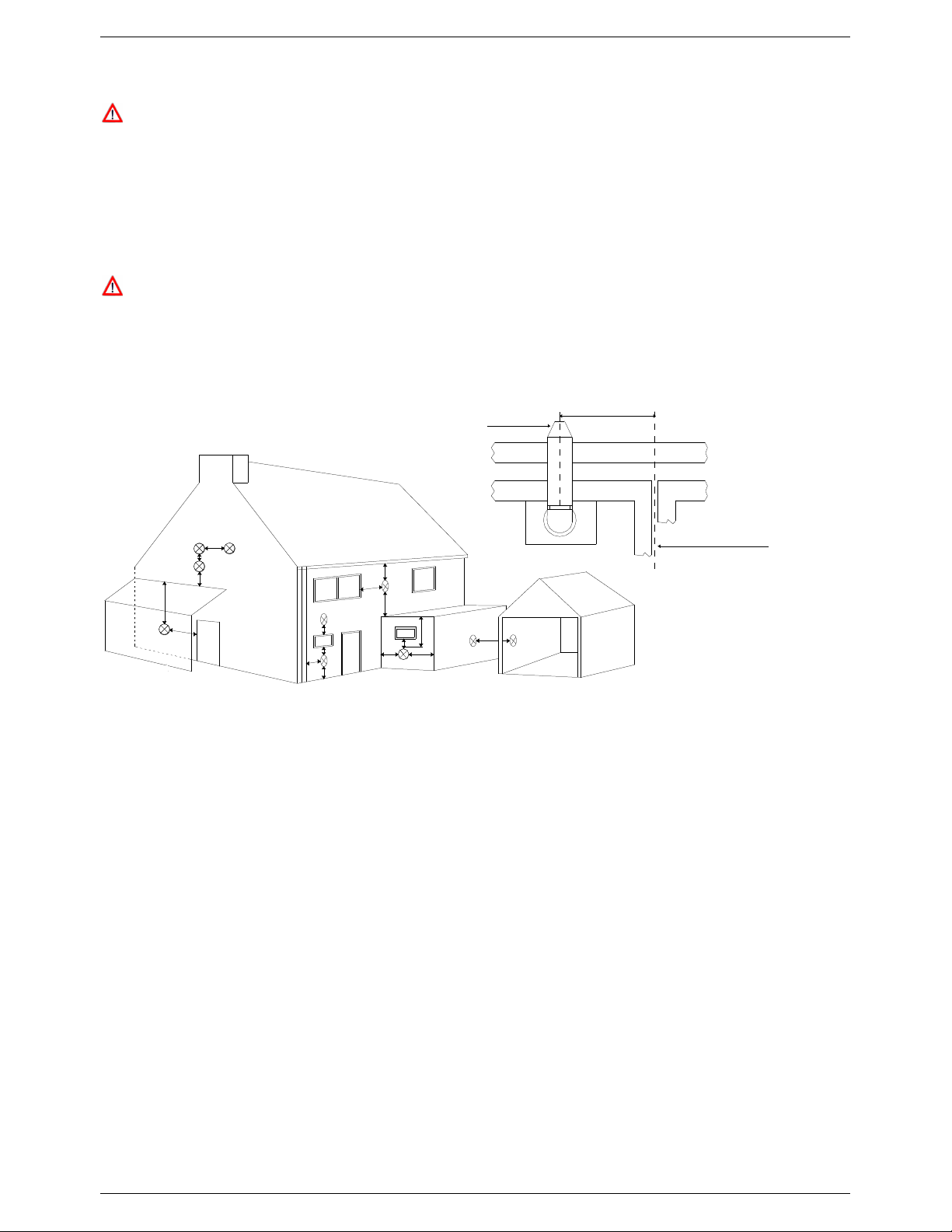
The flue system MUST be installed in accordance with the recommendation contained in BS 5440:1.
The boiler MUST be installed so that the terminal is exposed to the external air.
It is important that the position of the terminal allows free passage of air across it at all times.
If the terminal discharges into a pathway or passageway check that combustion products will not cause nuisance
and that the terminal will not obstruct the passageway.
In certain weather conditions a terminal may emit a plume of steam. Positions where this would cause a nuisance
should be avoided.
It is ESSENTIAL TO ENSURE, in practice, that products of combustion discharging from the terminal
cannot re-enter the building, or any other adjacent building, through ventilators, windows, doors, other
sources of natural air infiltration, or forced ventilation/air conditioning systems. If this should occur,
the appliance MUST BE TURNED OFF IMMEDIATELY.
Where the lowest part of the terminal is fitted less than 2m (6.6ft) above a balcony, above ground, or above a flat
roof to which people have access, the terminal MUST be protected by a purpose designed guard.
L
K
G
D
J
M
A
E
G
N
B.C
G
F F
D
A
TERMINAL
ASSEMBLY
H,I
TOP VIEW REAR FLUE
PROPERTY BOUNDARY LINE
Figure 17: Flue terminal positions – BS5440:1
A Directly below an opening window, air vent or any other ventilation opening 300 mm
B Below gutter, drain pipes or soil pipes 75 mm
C Below eaves 200 mm
D Below balcony or carport roof 200 mm
E From vertical drain pipes or soil pipes 150 mm
F From internal or external corners 300 mm
G Above adjacent ground, roof or balcony level 300 mm
H From a surface or boundary facing the terminal 600 mm
I From a terminal facing the terminal 1200 mm
J From opening (door, window) in the carport into dwelling 1200 mm
K Vertically from a terminal on the same wall 1500 mm
L Horizontally from a terminal on the same wall 300 mm
M Above an opening, air brick, opening window etc 300 mm
N Horizontally to an opening, air brick, opening window, etc. 300 mm
TR05A140.B1107
25
Page 28
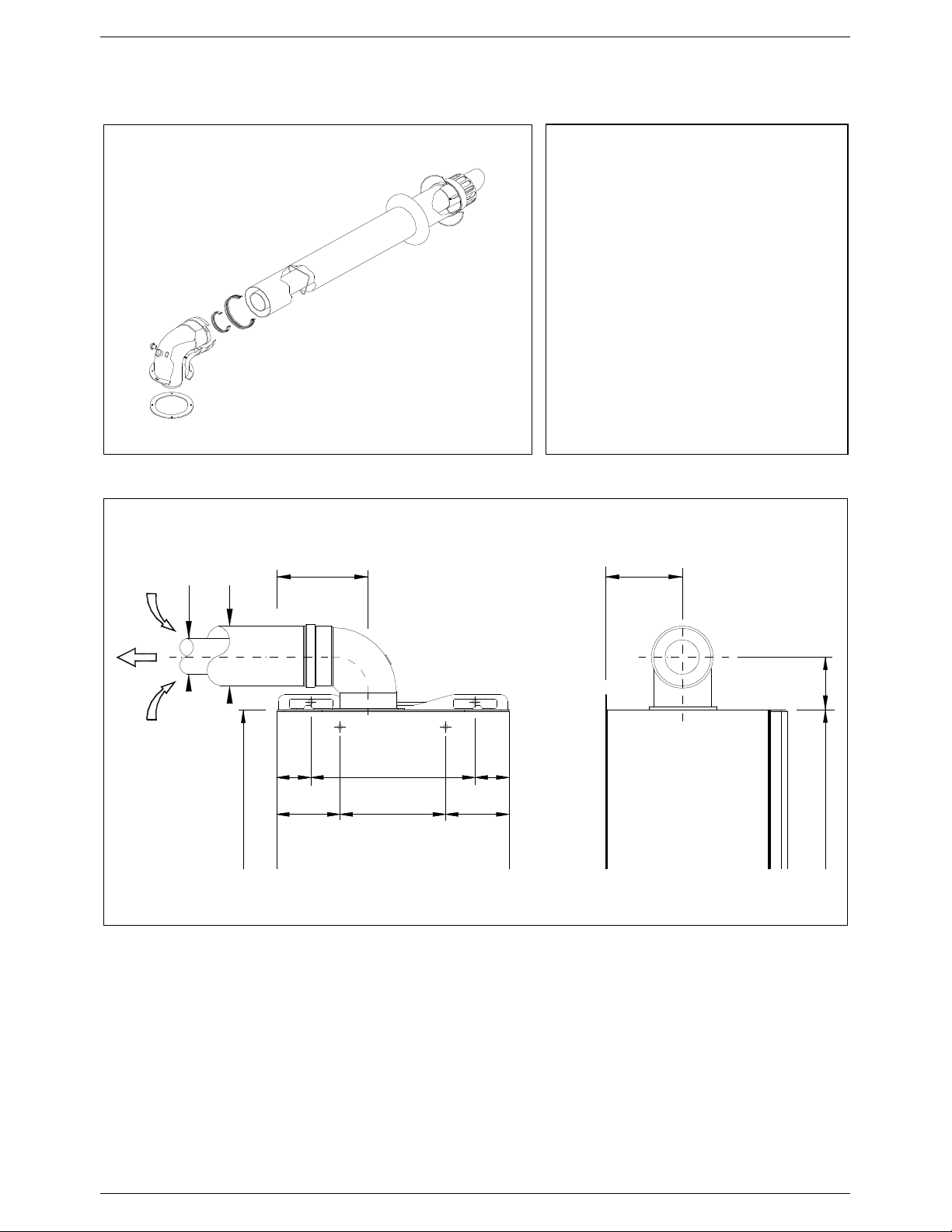
INSTALLATION INSTRUCTIONS
4.8.2 Horizontal coaxial balanced flue – Ø 60/100 (Kit K)
FOR CONDENSING BOILERS ONLY
Ø 60/100
MAXIMUM FLUE LENGTH = 5 m *
The flue length is the total length of the flue
excluding the first bend.
The total length is calculated by summing
the lengths of all the straight section AND
the equivalent lengths of each bend (see
below).
Ø 80/125 x 90° bend = 0.8 m
Ø 80/125 x 45° bend = 0.5 m
* If a flue length of above 5 metres is
required, use the Ø 80/125 system.
Figure 18: Ø 60/100 Horizontal Kit K
163
60
100
48.5 313 48.5
Figure 19: Ø 60/100 Horizontal Kit K dimensions
132
97
111.5187111.5
TR05A140.B1107
26
Page 29
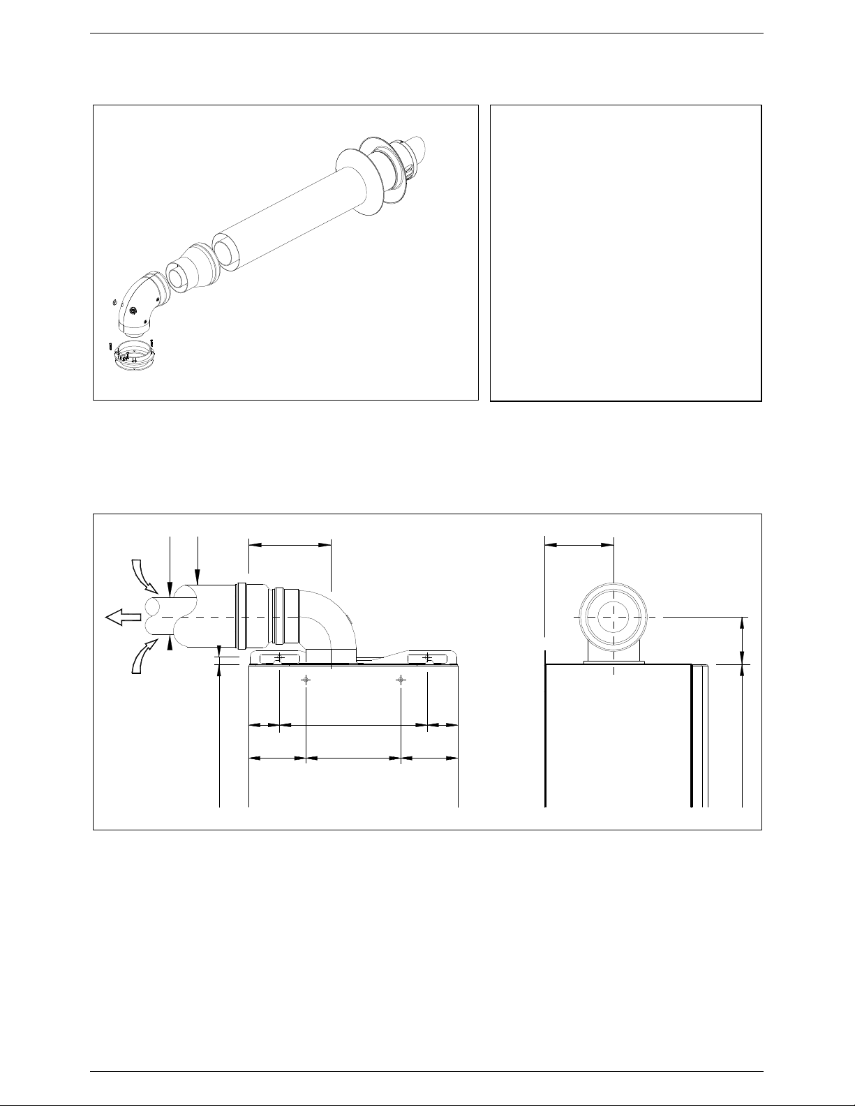
INSTALLATION INSTRUCTIONS
Figure
20: Ø
80/125 Horizontal Kit
4.8.3 Horizontal coaxial balanced flue – Ø 80/125
FOR CONDENSING BOILERS ONLY
Ø 80/125
MAXIMUM FLUE LENGTH = 7 m *
The flue length is the total length of the flue
excluding the first bend.
The total length is calculated by summing
the lengths of all the straight section AND
the equivalent lengths of each bend (see
below).
Ø 80/125 x 90° bend = 0.8 m
Ø 80/125 x 45° bend = 0.5 m
* If a flue length of above 7 metres is
required, use the Twin Pipe system.
163
80
125
15
48.5 313 48.5
Figure 21: Ø 80/125 Horizontal Kit dimensions
132
97
111.5187111.5
TR05A140.B1107
27
Page 30
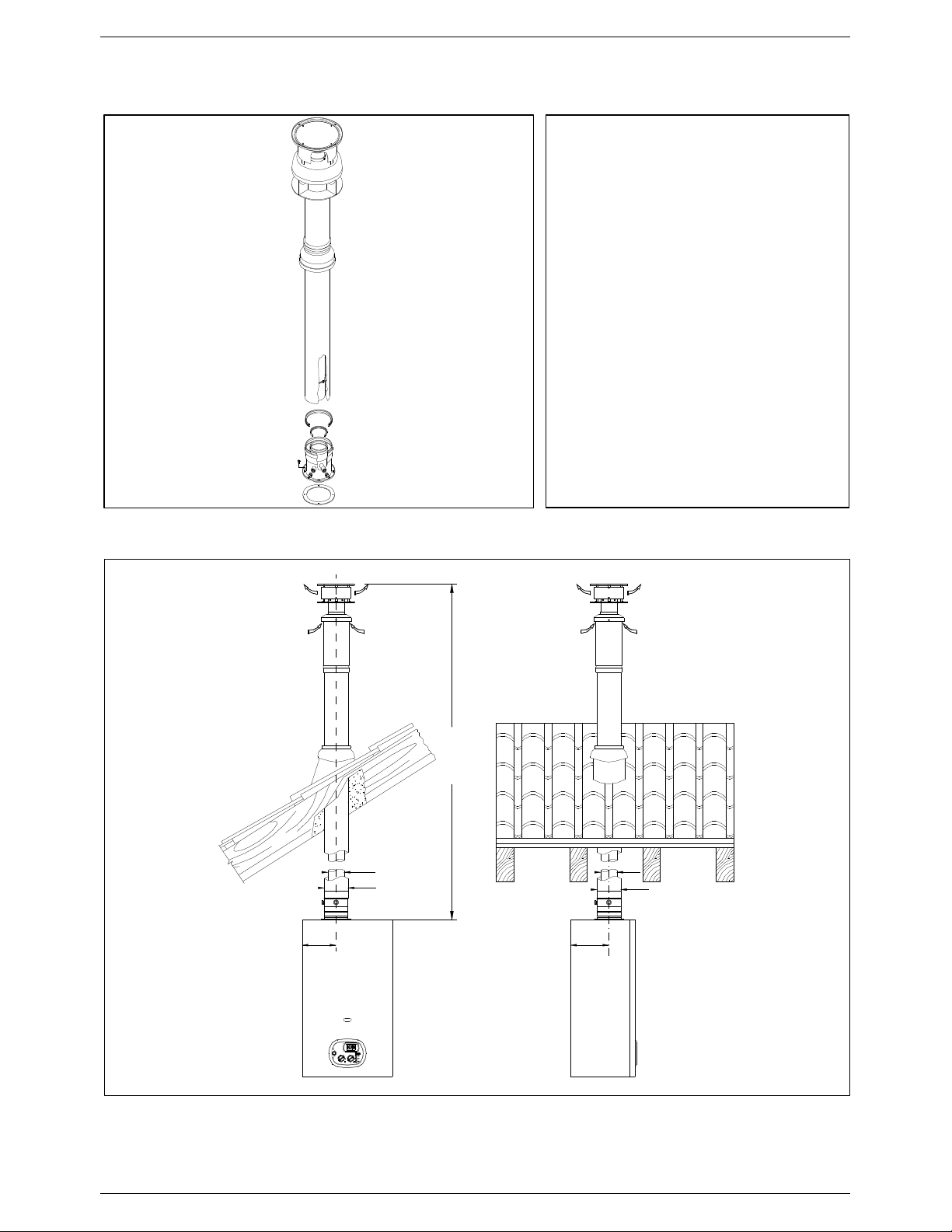
INSTALLATION INSTRUCTIONS
4.8.4 Vertical coaxial balanced flue – Ø 60/100 (Kit V)
Figure 22: Ø 60/100 Vertical Kit V
FOR CONDENSING BOILERS ONLY
Ø 60/100
MAXIMUM FLUE LENGTH = 5 m *
The flue length is the total length of the flue
excluding the first bend.
The total length is calculated by summing
the lengths of all the straight section AND
the equivalent lengths of each bend (see
below).
Ø 80/125 x 90° bend = 0.8 m
Ø 80/125 x 45° bend = 0.5 m
* If a flue length of above 5 metres is
required, use the Ø 80/125 system.
max. 5.00 mt.
Ø60
Ø100
163
Ø60
Ø100
131
Figure 23: Ø 60/100 Vertical Kit V dimensions
TR05A140.B1107
28
Page 31
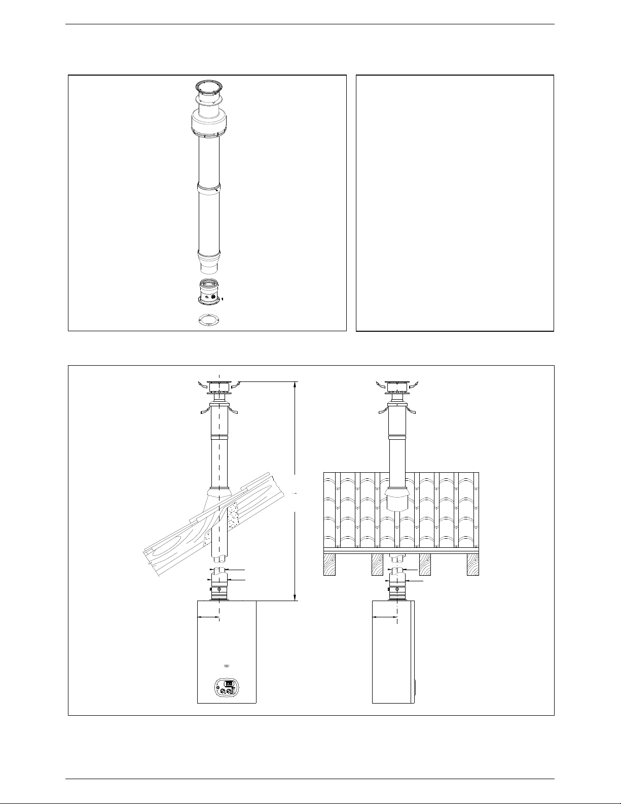
INSTALLATION INSTRUCTIONS
4.8.5 Vertical coaxial balanced flue – Ø 80/125
Figure 24: Ø 80/125 Verical Kit
FOR CONDENSING BOILERS ONLY
Ø 80/125
MAXIMUM FLUE LENGTH = 7 m *
The flue length is the total length of the flue
excluding the first bend.
The total length is calculated by summing
the lengths of all the straight section AND
the equivalent lengths of each bend (see
below).
Ø 80/125 x 90° bend = 0.8 m
Ø 80/125 x 45° bend = 0.5 m
* If a flue length of above 7 metres is
required, use the Twin Pipe system.
7
max. 5.00 mt.
Ø60
Ø100
163
Ø60
Ø100
131
Figure 25: Ø 80/125 Verical Kit dimensions
TR05A140.B1107
29
Page 32
INSTALLATION INSTRUCTIONS
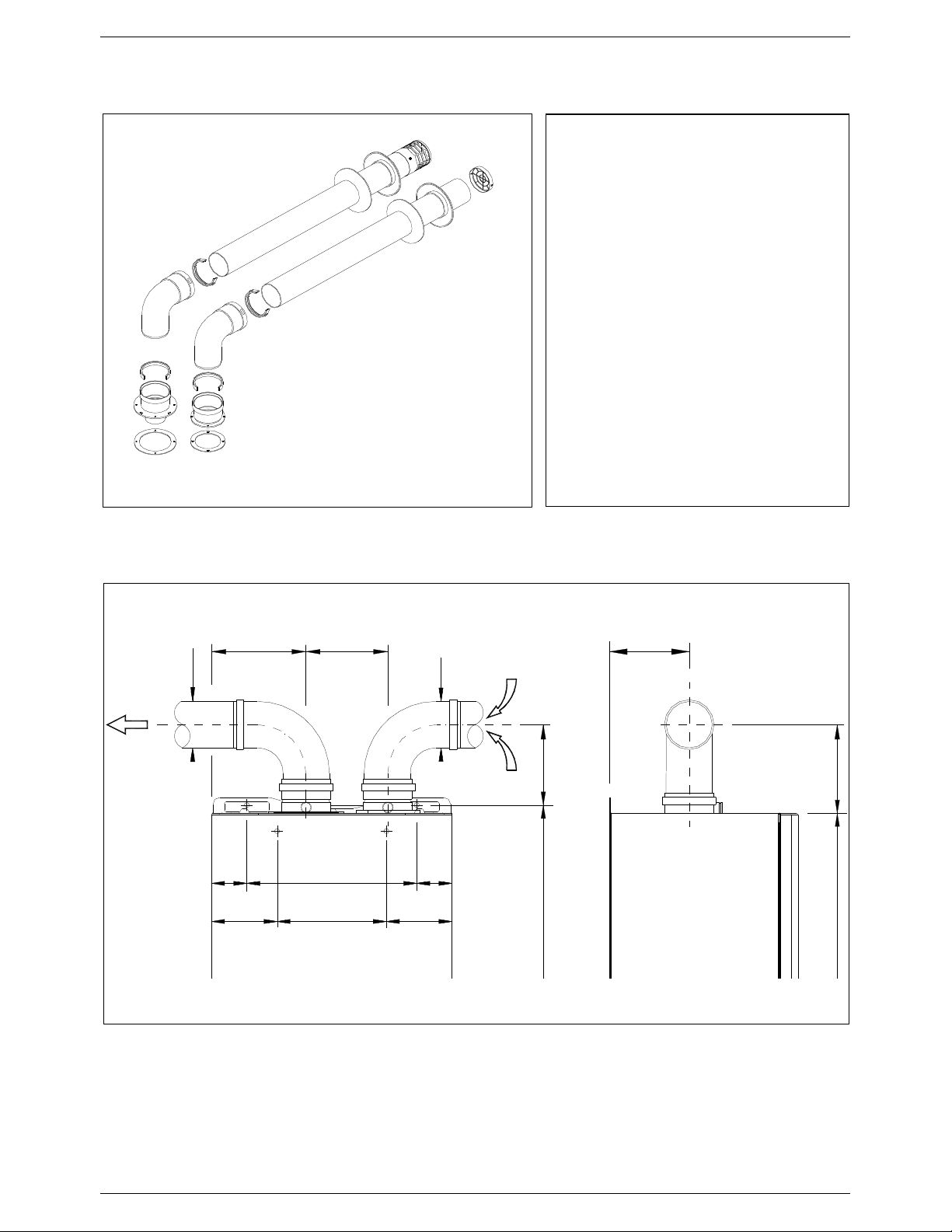
4.8.6 Twin pipe flue system – Ø 80/80 (Kit H)
FOR CONDENSING BOILERS ONLY
Ø 80/80
MAXIMUM FLUE LENGTH = 50 m
The flue length is the total length of both
the intake and exhaust sections excluding
the first bend of each.
The total length is calculated by summing
the lengths of all the straight section AND
the equivalent lengths of each bend (see
below).
Ø 80 x 90° bend = 1.5 m
Ø 80 x 45° bend = 1.2 m
Figure 26: Ø 80/80 Twin Pipe Kit H
163 137
80
111.5 187 111.5
131
80
106
122
48.531348.5
Figure 27: Ø 80/80 Twin Pipe Kit H dimensions
TR05A140.B1107
30
Page 33

COMMISSIONING INSTRUCTIONS
5 COMMISSIONING
5.1 General warnings
The following operations must be carried out by professionally qualified personnel, registered in
accordance with current legislation. Reference should be made to BS 5449:5 - Commissioning.
The boiler leaves the factory pre-set and tested for burning Natural Gas (Methane). Nevertheless, when
starting the boiler for the first time, make sure that the information on the rating plate corresponds to
the type of gas being supplied to the boiler.
Once the system has been filled and the necessary adjustments made, remember to tighten the screws
of the gas valve test point and make sure that there are no gas leaks from the test point and from any
pipe fittings upstream of the gas valve.
■ Preliminary operations
Switching the boiler on for the first time means checking that the installation, regulation and operation of the
appliance are correct. The commissioning engineer MUST check, referring to the previous sections of this manual,
the following:-
• That the data on the data plate corresponds to that of the mains supply networks (gas, electricity, water);
• That the power supply voltage to the boiler complies with the data plate (230 V – 50 Hz) and that the live, neutral
and earth wires are correctly connected. Also, that the earth connection is sound and that the appliance is
effectively earthed;
• That the gas supply is correctly sized for the flow rate required by the boiler and that it is fitted with all the safety
and control devices as lay down by current regulations;
• That all mechanical connections are sound and have not become loose during transportation and handling;
• That the seals on the gas supply pipe from the mains are sound, and that the meter does not register any flow of
gas;
• That the flue system (air intake and exhaust ducts) is installed correctly and in line with current law and national
and local standards;
• The all permanent combustion air and ventilation openings as required by current law for the type of appliances
installed are provided and are not blocked;
• That the condensate drainage system(s) are installed correctly and in line with current law and national and local
standards;
• That the condensate drainage system, including outside the boiler (condensate collection devices), allows the
condensate to flow freely to the drain. Check that no exhaust fumes could discharge into the drainage system;
• That there are no flammable materials or liquids in the immediate vicinity of the boiler.
The commissioning engineer must then:-
• Flush out the central heating circuit (see Section 5.3);
• Turn the gas supply on and purge according to BS6891.
• Test for gas soundness (let-by and tightness).
TR05A140.B1107
31
Page 34
5.2 Filling the system
Use only a WRAS approved filling loop
for connection and filling of the primary
system. This should be disconnected
when not in use (see Section 4.4.2).
COMMISSIONING INSTRUCTIONS
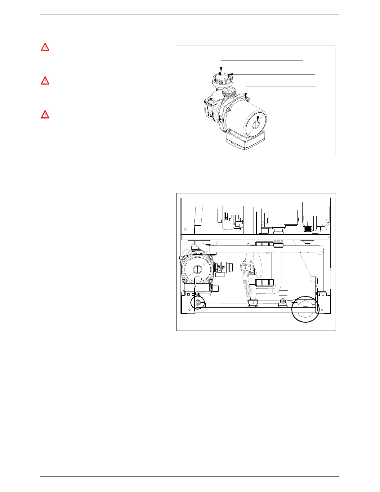
AIR VENT VALVE
AIR VENT VALVE PLUG
Check the properties of the water supply
and use appropriate treatment agents if
the mains water has a hardness rating
more than 17.5 °Ck.
Use only clean tap water to fill the
system.
Once the water pipes have been connected,
close the gas feed valve and fill the system as
follows:
• Slacken the air vent valve plug to allow air to
escape from the system (see Figure 28);
• Open the main domestic water supply valve;
• Open the external filling loop;
• Unscrew the pump plug to remove any
trapped air, check that the pump is free then
re-tighten it when water starts to flow out;
• Unscrew the manual air vent valve located in
the top left hand corner of the primary heat
exchanger until air begins to escape. When
water begins to flow out, screw the valve
tightly closed.
• Open the air vents on the radiators and
monitor the air evacuation process. When
water starts to flow out of the radiators, close
the air vents;
PUMP
PUMP PLUG
Figure 28: Air vent and pump bleed plugs
• Use the pressure gauge M (see Figure 29) to
monitor the system pressure. Close the
external filling loop when the system pressure
reaches 1 bar and check that Error Code
H2O is NOT displayed on the control panel
display (see Section 3.6);
• If, after the above operations, there is a
reduction in the system pressure, re-open the
external filling loop until the pressure gauge
reads 1 bar. Check that Error Code H2O is
NOT displayed on the control panel display;
• On completion of filling, ensure that the external filling loop is disconnected.
Figure 29: Pressure gauge and boiler drain
RS
M
TR05A140.B1107
32
Page 35
COMMISSIONING INSTRUCTIONS
5.3 Flushing the system
Failure to flush and add inhibitor to the system will invalidate the warranty.
The system must be thoroughly drained and flushed out using flushing agents/descalers that comply
with BS7593. When refilling the system, appropriate corrosion inhibitors and softening agents must be
added.
a. Fill the boiler as per the filling instructions;
b. Using a drain cock on the lowest point of the system, allow the water to drain from both the system and boiler;
c. To flush the system correctly, turn off all radiators, open the filling loop and drain cock simultaneously and allow
the water to flow through the boiler;
d. For each radiator on the system in turn, open the radiator valves, allowing water to flow through, then turn that
radiator off. Repeat for all the radiators on the system;
e. Close the drain cock, re-open all radiators and fill the system following the instructions in Section 5.2;
a. Continue to fill the system until the pressure gauge reaches 1 bar.
5.4 Filling the condensate trap
The condensation trap MUST be pre-filled when starting the boiler for the first time in order to prevent flue gases
from escaping via the drain.
The filling operation is carried out as follows (see Figure 30):
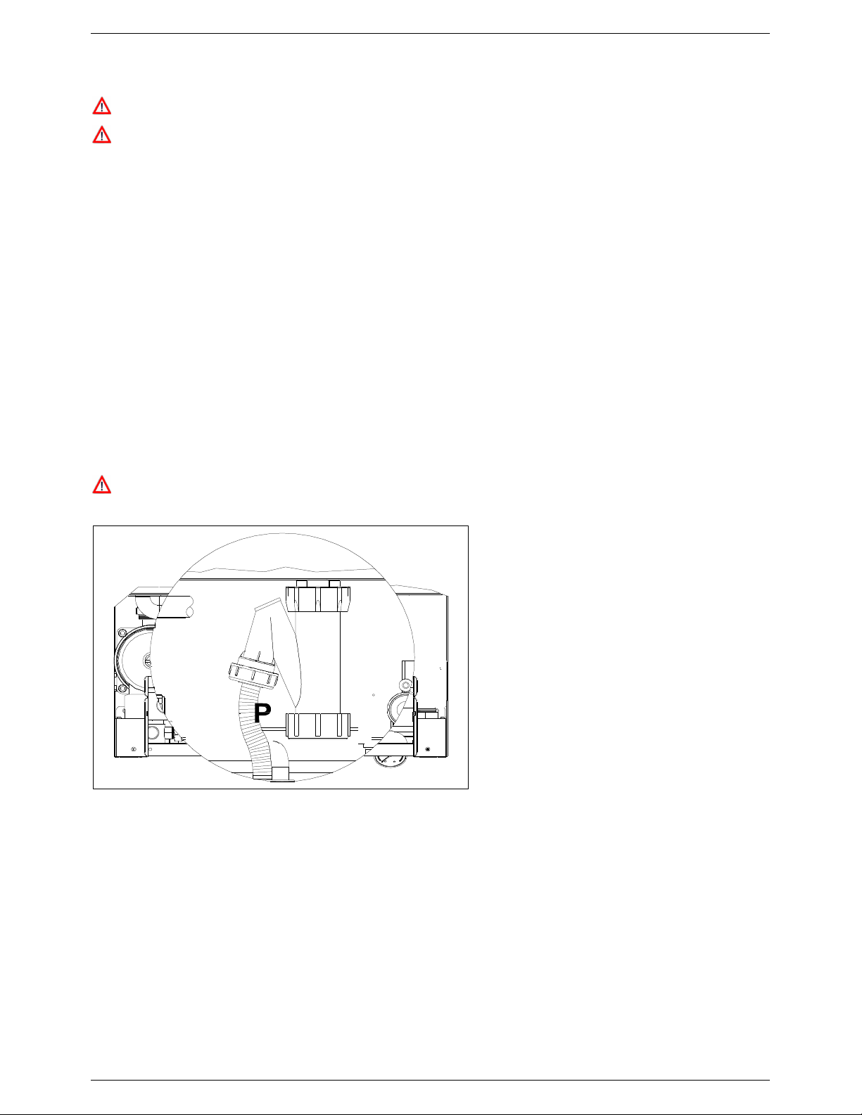
• Remove plug T and fill the trap S three quarters full with water;
• Replace plug T and connect the drainpipe P.
The trap should be cleaned after a few months of boiler operation, as deposits/residues drawn out of
the heat exchanger may impair the operation of the trap.
T
S
Figure 30: Condensate Trap
TR05A140.B1107
33
Page 36
5.5 Starting the boiler
COMMISSIONING INSTRUCTIONS
Once the system has been flushed and filled,
proceed as follows:
• Check that the exhaust flue is free of
obstructions and correctly connected to the
boiler;
• Check that all isolation valve are open (CH
circuit and gas)
• Switch on the power supply to the boiler and
ensure that the system controls are calling
for heat;
• Switch the boiler on using the ON/OFF
button on the Control Panel (see Section
3.6) and ensure any system controls are
calling for heat. After a few seconds the
circulating pump will start to run;
• The automatic ignition system will then
attempt to fire the burner. The system will
make 3 attempts and then go to lock-out if
unsuccessful. It may be necessary to repeat
the process a few times in order to eliminate
all the air from the gas supply line. To repeat
the process, wait approximately three
minutes then reset the appliance by
switching the boiler off then on using the
ON/OFF button on the Control Panel;
Gas Type CO2 Concentration / %
Natural Gas (Methane) – G 20
LPG (Butane) – G 30 10.9
LPG (Propane) – G 31 11.0
Table 5: Correct gas analyser readings
9.4
PF
• With the boiler ignited, if the system still
emits noises, the above process must be
repeated until all the air has been removed;
• Check the pressure in the heating circuit
using the pressure gauge (see Section 5.2).
If the pressure has fallen, re-open the filling
loop until the pressure gauge reads 1 bar.
Check that Error Code H2O is NOT
displayed on the Control Panel display. On
completion, close the filling loop;
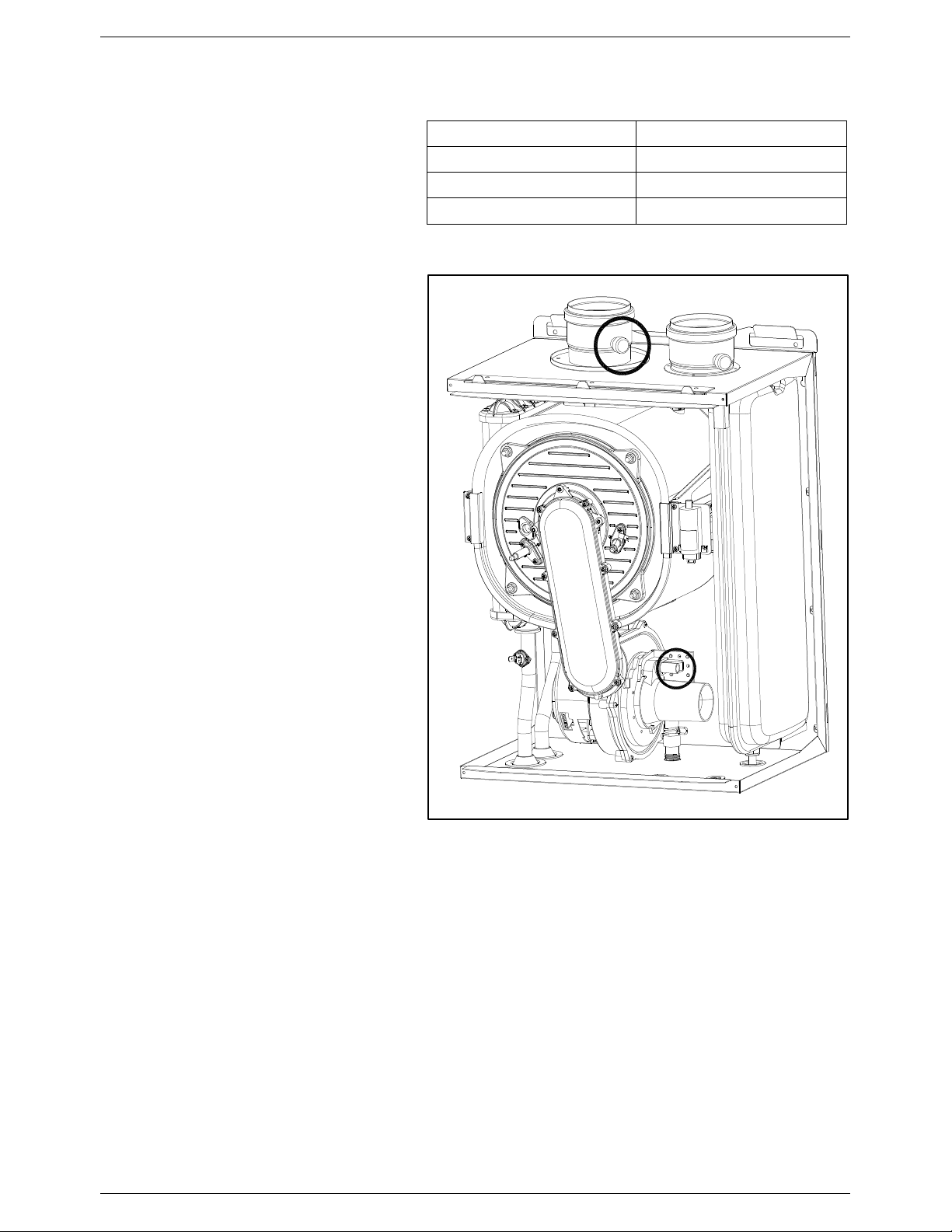
• Unscrew the plug and insert an analyser in
the exhaust sampling point PF (see Figure
31 – twin pipe flue system depicted) to check
the CO2 value. The value should correspond
to those in Table 5;
• If the CO2 value does not correspond to those in the table, adjust screw V on the venturi (see Figure 31)
clockwise to reduce the CO2 value or anticlockwise to increase it.
Figure 31: Flue sampling and commissioning points
V
TR05A140.B1107
34
Page 37
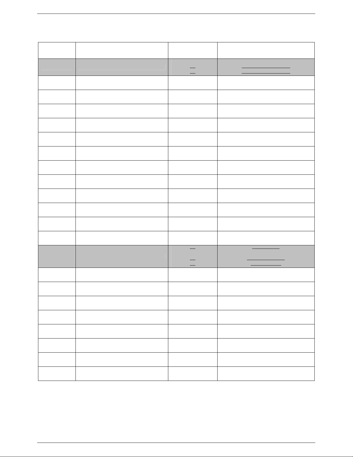
5.6 Control parameters
COMMISSIONING INSTRUCTIONS
PARAMETER
NUMBER
PARAMETER NAME
1 Boiler type
2 Fuel type
3 CH flow temperature
4 CH pump mode
PARAMETER
VALUE
00
01
02
00
01
00
01
00
01
FUNCTION
Non-storage boiler
Storage boiler (type 1)
Storage boiler (type 2)
Natural gas
LPG
Standard (30-80°C) for radiators
Reduced (25-40°C) for under floor
Runs when controls call for heat.
Runs continuously when appliance is on.
5 - - Not applicable to this appliance
6
Short cycling prevention
(CH delay timer)
7 CH pump overrun timer
00-90
(default = 36)
00-90
(default = 36)
Expressed in steps of 5 seconds
(Default = 36 x 5 sec = 180 sec)
Expressed in steps of 5 seconds
(Default = 36 x 5 sec = 180 sec)
8 - - Not applicable to this appliance
9 - - Not applicable to this appliance
10 - - Not applicable to this appliance
11 - - Not applicable to this appliance
12 - - Not applicable to this appliance
13 - - Not applicable to this appliance
14 Burner type
00
01
02
03
Atmospheric
Premix 25 kW
Premix 29-34 kW
Premix 50 kW
15 - - Not applicable to this appliance
16 - - Not applicable to this appliance
17 Minimum fan speed
18 Maximum fan speed
19 Minimum fan speed (in CH mode)
20 Maximum fan speed (in CH mode)
21 Ignition sequence fan speed
22 Fan speed display mode
33-202
(default = 66)
33-202
(default = 162)
33-202
(default = 66)
33-202
(default = 162)
33-202
(default = 110)
00
01
Expressed in Hertz (Hz)
(Default = 66 Hz)
Expressed in Hertz (Hz)
(Default = 162 Hz)
Expressed in Hertz (Hz)
(Default = 66 Hz)
Expressed in Hertz (Hz)
(Default = 162 Hz)
Expressed in Hertz (Hz)
(Default = 110 Hz)
Off
On (displays fan speed for 10 minutes)
Table 6: Control Parameters
NOTES
Factory default values highlighted in bold.
Parameters 1 and Parameter 14 highlighted in grey only need to be adjusted when replacing the Modulation PCB. When the
PCB is replaced and Parameter 14 is set to values 01, 02 or 03 the PCB will automatically set Parameters 17 through 22 to the
factory default values stated above.
TR05A140.B1107
35
Page 38
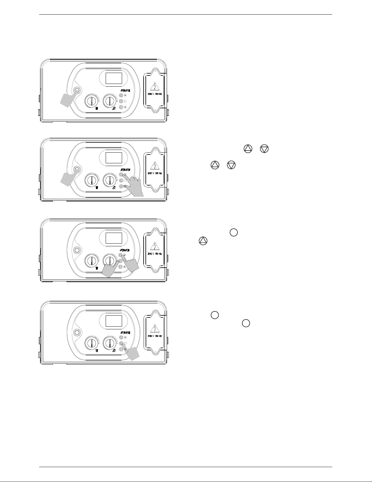
COMMISSIONING INSTRUCTIONS
S
S
S
5.7 Control parameter adjustment
5.7.1 Accessing the parameters menu
OFF
S
PL
S
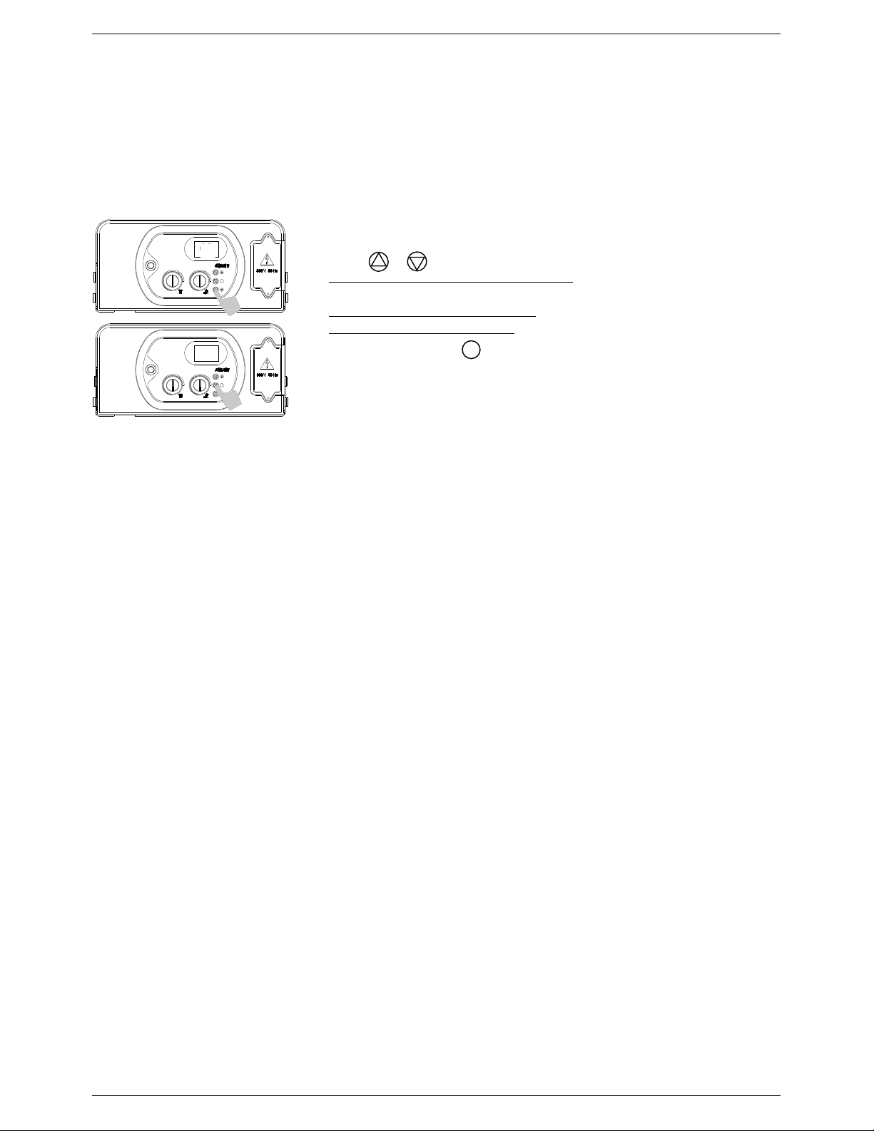
Step 1:
Switch the appliance off using the ON/OFF button.
Step 2:
Press and hold both the & buttons.
Switch the appliance on using the
ON/OFF
button.
Release the & buttons.
Step 3:
Press and hold the
0
S
Use the button to cycle up through the parameters.
Step 4:
Release the
1
Press and release the
button.
button.
button again.
The value of the selected parameter will be displayed.
S
Follow the instructions in the following section (Section
5.7.2) to adjust parameter values.
TR05A140.B1107
36
Page 39
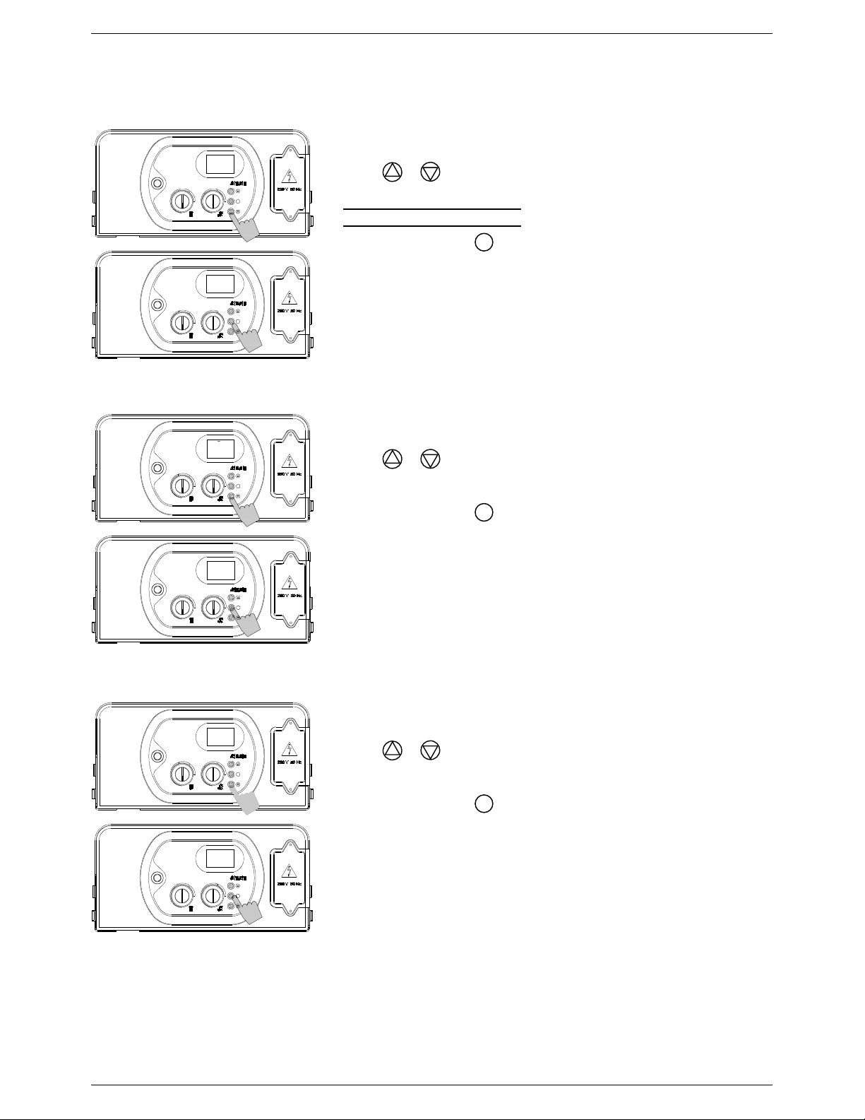
5.7.2 Adjusting the parameters
S
S
S
00
00
S
1
S
01
S
2
COMMISSIONING INSTRUCTIONS
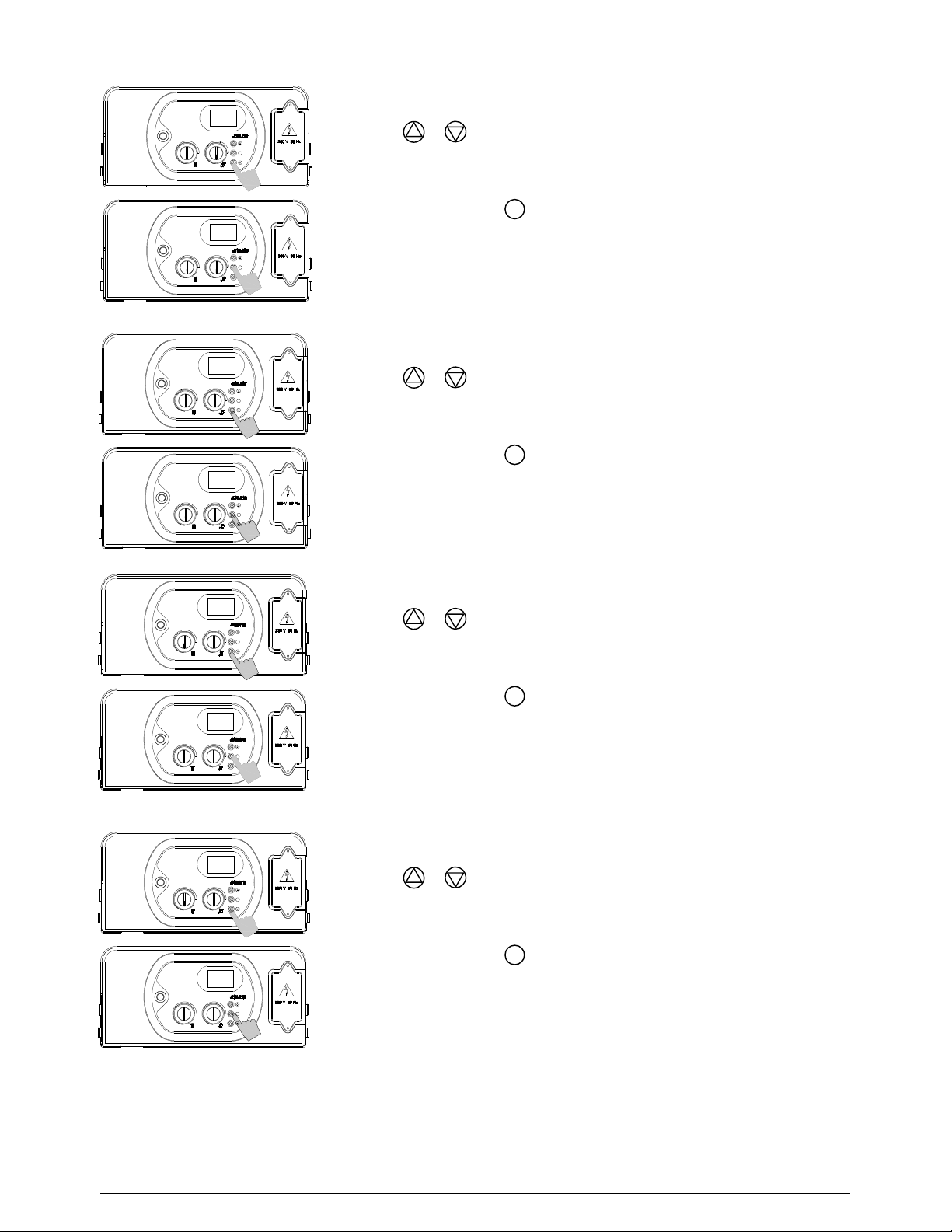
Parameter 1 – Boiler type
Access the parameters menu as described in Section 5.7.1.
Use the & buttons to adjust the parameter value:
00 = Non-storage boiler;
01 = Storage boiler (type 1);
02 = Storage boiler (type 2).
Press and release the
button.
The parameter number (1) will appear on the display.
To store your changes, switch the appliance off then on again using
the ON/OFF button.
Parameter 2 – Fuel type
Access the parameters menu as described in Section 5.7.1.
Use the & buttons to adjust the parameter value:
00 = Natural gas (Methane)
01 = LPG
Press and release the
button.
The parameter number (2) will appear on the display.
To store your changes, switch the appliance off then on again using
the ON/OFF button.
00
3
S
Parameter 3 – CH flow temperature
Access the parameters menu as described in Section 5.7.1.
Use the & buttons to adjust the parameter value:
S
00 = Standard (30 – 80°C) for radiators
01 = Reduced (25 – 40°C) for under-floor heating
Press and release the
button.
The parameter number (3) will appear on the display.
To store your changes, switch the appliance off then on again using
the ON/OFF button.
S
TR05A140.B1107
37
Page 40
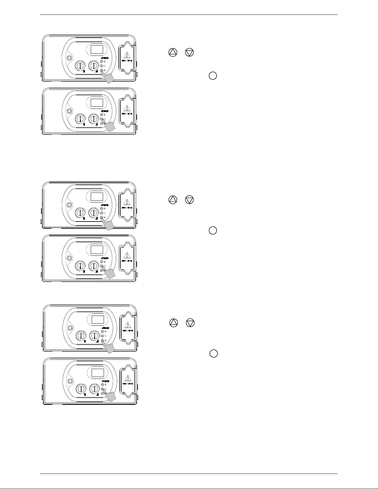
COMMISSIONING INSTRUCTIONS
S
S
S
00
4
6
Parameter 4 – CH pump mode
Access the parameters menu as described in Section 5.7.1.
36
S
Use the & buttons to adjust the parameter value:
00 = Runs when controls call for heat
01 = Runs continuously when appliance is on
Press and release the
button.
The parameter number (4) will appear on the display.
To store your changes, switch the appliance off then on again using
7
S
the ON/OFF button.
Parameter 5
Not applicable to this appliance
36
S
Parameter 6 – Short-cycling prevention (CH delay timer)
Access the parameters menu as described in Section 5.7.1.
Use the & buttons to adjust the parameter value:
00 = 0 x 5 seconds = 0 seconds (minimum)
90 = 90 x 5 seconds = 450 seconds (maximum)
Note: Factory preset to 36 = 180 seconds
Press and release the
button.
The parameter number (6) will appear on the display.
7
To store your changes, switch the appliance off then on again using
the ON/OFF button.
S
36
S
Parameter 7 – CH pump overrun timer
Access the parameters menu as described in Section 5.7.1.
Use the & buttons to adjust the parameter value:
00 = 0 x 5 seconds = 0 seconds (minimum)
90 = 90 x 5 seconds = 450 seconds (maximum)
Note: Factory preset to 36 = 180 seconds
Press and release the
button.
The parameter number (7) will appear on the display.
7
S
To store your changes, switch the appliance off then on again
using the ON/OFF button.
TR05A140.B1107
38
Page 41
S
02
01
14
COMMISSIONING INSTRUCTIONS
Parameters 8 through 13
Not applicable to this appliance
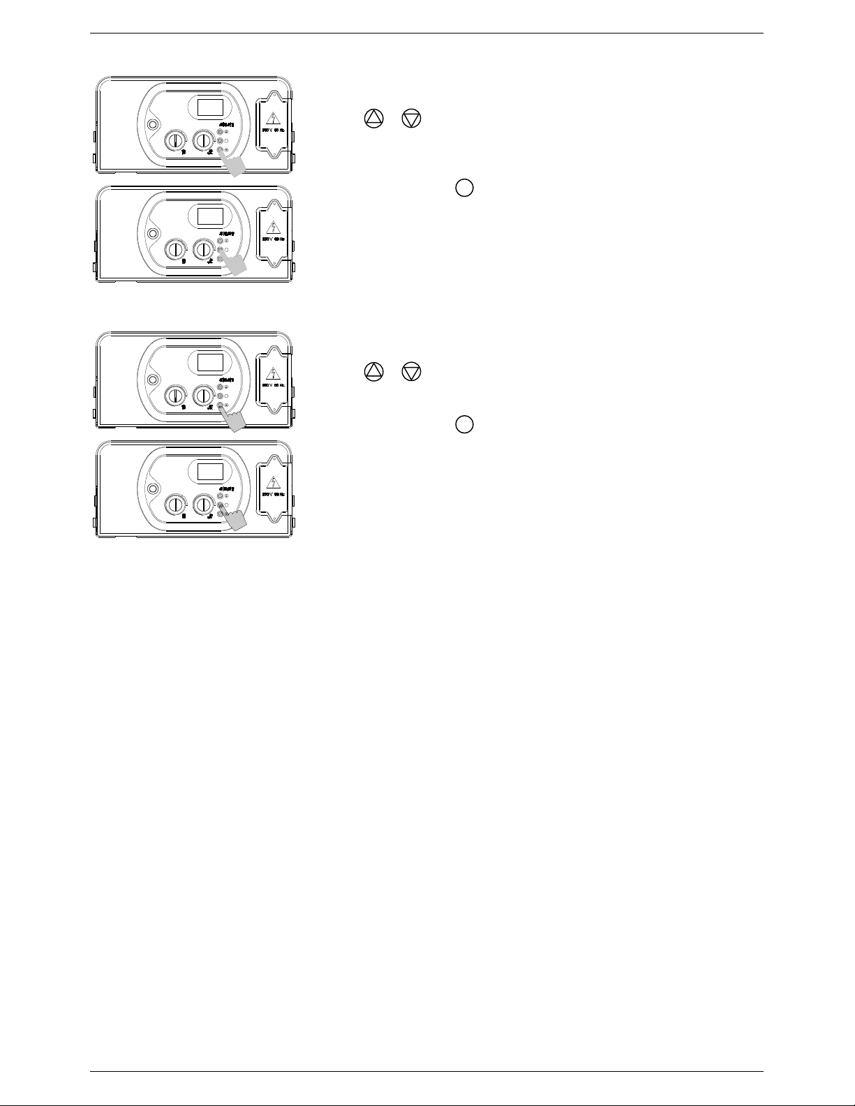
Parameter 14 – Burner type
Access the parameters menu as described in Section 5.7.1.
Use the & buttons to adjust the parameter value:
S
00 = Atmospheric burner (all outputs);
01 = Premix burner – 25 kW;
02 = Premix burner – 29-34 kW;
03 = Premix burner – 50 kW;
Press and release the
button.
The parameter number (14) will appear on the display.
S
To store your changes, switch the appliance off then on again using
the ON/OFF button.
Parameters 15 and 16
Not applicable to this appliance
TR05A140.B1107
39
Page 42
S
S
S
S
55
17
164
18
COMMISSIONING INSTRUCTIONS
Parameter 17 – Minimum fan speed
Access the parameters menu as described in Section 5.7.1.
Use the & buttons to adjust the parameter value:
S
33 = 33 Hz (minimum)
Maximum value determined by Parameter 18
Note: Factory preset to 66 = 66 Hz
Press and release the
button.
The parameter number (17) will appear on the display.
To store your changes, switch the appliance off then on again using
S
the ON/OFF button.
Parameter 18 – Maximum fan speed
Access the parameters menu as described in Section 5.7.1.
Use the & buttons to adjust the parameter value:
S
Minimum value determined by Parameter 17
202 = 202 Hz (maximum)
Note: Factory preset to 162 = 162 Hz
Press and release the
button.
The parameter number (18) will appear on the display.
To store your changes, switch the appliance off then on again using
S
the ON/OFF button.
55
19
164
20
Parameter 19 – Minimum fan speed (in CH mode)
Access the parameters menu as described in Section 5.7.1.
Use the & buttons to adjust the parameter value:
S
33 = 33 Hz (minimum)
Maximum value determined by Parameter 18
Note: Factory preset to 66 = 66 Hz
Press and release the
button.
The parameter number (19) will appear on the display.
To store your changes, switch the appliance off then on again using
S
the ON/OFF button.
Parameter 20 – Maximum fan speed (in CH mode)
Access the parameters menu as described in Section 5.7.1.
Use the & buttons to adjust the parameter value:
S
Minimum value determined by Parameter 17
202 = 202 Hz (maximum)
Note: Factory preset to 162 = 162 Hz
Press and release the
button.
The parameter number (20) will appear on the display.
To store your changes, switch the appliance off then on again using
S
the ON/OFF button.
TR05A140.B1107
40
Page 43
S
S
110
21
00
22
COMMISSIONING INSTRUCTIONS
Parameter 21 – Ignition sequence fan speed
Access the parameters menu as described in Section 5.7.1.
Use the & buttons to adjust the parameter value:
S
Minimum value determined by Parameter 17
Maximum value determined by Parameter 18
Note: Factory preset to 110 = 110 Hz
Press and release the
button.
The parameter number (21) will appear on the display.
To store your changes, switch the appliance off then on again using
S
the ON/OFF button.
Parameter 22 – Fan speed display mode
Access the parameters menu as described in Section 5.7.1.
Use the & buttons to adjust the parameter value:
S
00 = Off
01 = On (Fan speed displayed for 10 minutes)
Press and release the
button.
The parameter number (22) will appear on the display.
To store your changes, switch the appliance off then on again using
the ON/OFF button.
S
TR05A140.B1107
41
Page 44
COMMISSIONING INSTRUCTIONS
5.8 Gas data
5.8.1 Technical reference tables
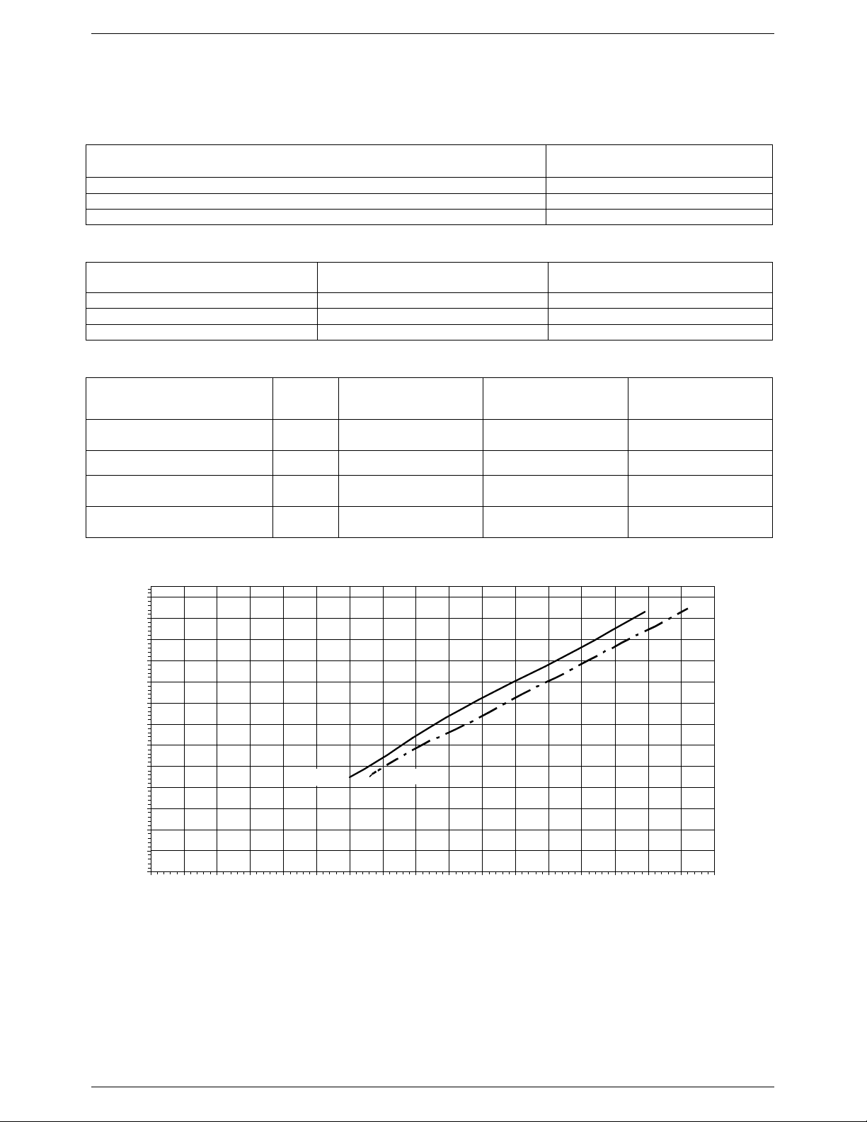
Gas Type CO2 Concentration / %
Natural Gas (Methane) – G20 9.4
LPG (Butane) – G30 10.9
LPG (Propane) – G31 11.0
Table 7: Reference Carbon Dioxide concentrations
Gas Type Minimum Fan Speed / Hz Maximum Fan Speed / Hz
Natural Gas (Methane) – G20 66 162
LPG (Butane) – G30 60 149
LPG (Propane) – G31 60 149
Table 8: Reference fan speeds
Lower Wobbe index
(15ºC; 1013 mbar)
MJ/Nm3 45.67 80.58 70.69
Natural Gas
G20
Liquid Butane Gas
G30
Liquid Propane Gas
G31
Nominal Supply Pressure mbar 20 30 37
Consumption
(15ºC; 1013 mbar)
Consumption
(15ºC; 1013 mbar)
m3/h 2.64 - -
kg/h - 1.97 1.94
Table 9: Reference gas data
26
24
22
20
18
16
14
12
10
Portata termica kW
Heating Power kW
8
6
4
2
0
0 10 20 30 40 50 60 70 80 90 100 110 120 130 140 150 160 170
G30 G31
G20
Fan Frequency Hz
Frequenza Hz
Figure 32: Heating Output vs Fan Frequency
TR05A140.B1107
42
Page 45

MAINTENANCE INSTRUCTIONS
6 MAINTENANCE
6.1 General warnings
All maintenance operations must be carried out by professionally qualified personnel.
The frequency of boiler maintenance must comply with current law and should, in any case, be carried
out annually.
In order to guarantee the long life of the appliance, and in accordance with the current gas safety
regulations, only use original spare parts.
Before carrying out any type of maintenance operation, disconnect the appliance from the mains
electricity supply and close the gas valve.
6.2 Boiler inspection
In order to ensure that the boiler operates efficiently and safely, it is recommended that the appliance is inspected
by a suitably competent technician at least once a year.
The following must be checked annually:
■ The condition of the gas seals – replace where necessary;
■ The condition of the water seals – replace where necessary;
■ The condition of the combustion chamber and flame;
■ The combustion parameters – if necessary adjust in line with Sections 5.6 & 5.7;
■ The condition of the burner – remove any oxidation and clean if necessary;
■ The seal of the room sealed chamber is undamaged and positioned correctly;
■ The condition of the primary heat exchanger – clean if necessary;
■ The maximum and minimum modulation fan speeds and the modulation process itself – adjust if necessary;
■ The condition and operation of the ignition and gas safety systems – if necessary remove and clean any scaling
from the ignition and flame detection electrodes, paying particular attention to replace them at the correct
distance from the burner (see Section 6.6.2);
■ The heating safety systems: temperature and pressure limit devices – replace where necessary;
■ The system pre-charge pressure (should be 1 bar when cold) – if necessary refer to Section 5.2;
■ The integrity and operation of the flue system – correct where necessary;
■ That the mains electricity supply is safe and correctly rated (refer to Section 4.7) – correct where necessary;
■ The electrical connections inside the control panel – correct where necessary;
■ That the condensate drainage system is working correctly, including any parts of the system outside the boiler
such as condensate collection devices along the length of the flue and/or any acid neutralising devices – correct
where necessary;
■ That the condensate flows freely and that no exhaust fumes are present within the appliance or drainage system
– correct where necessary.
TR05A140.B1107
43
Page 46
MAINTENANCE INSTRUCTIONS
Figure
35
: Control panel access
6.3 Accessing the boiler
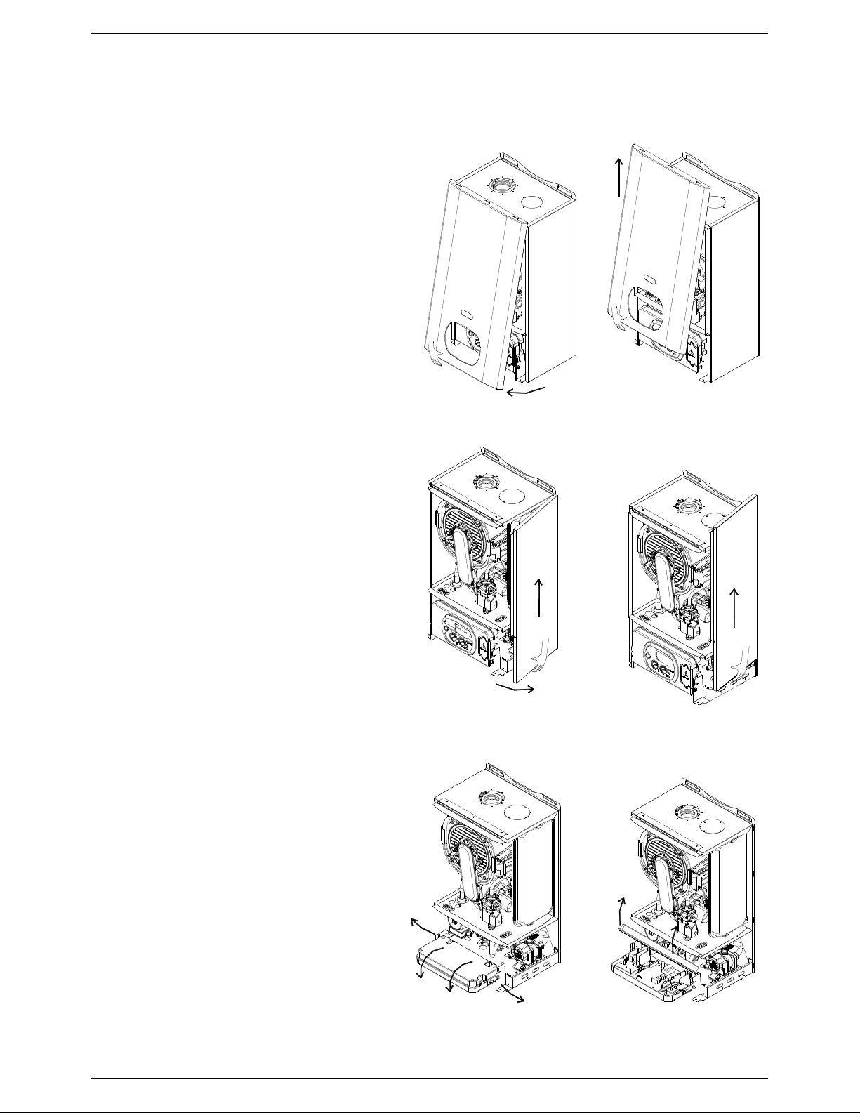
All maintenance operations require one or more of the boiler casing panels to be removed.
6.3.1 Front panel removal
• Remove the fixing screws at the lower edge of
the front panel;
• Grasp the lower part of the panel and pull it
outwards and then upwards (see Figure 33).
Figure 33: Front panel removal
6.3.2 Side panel removal
• The side panels can only be removed after the
front panel has been removed;
• Remove the fixing screws at the front and lower
edge of the side panel;
• Grasp the bottom of the panel, move it
sideways and then upwards (see Figure 34).
6.3.3 Control panel access
• Remove the front panel (refer to 6.3.1 above);
• Grasp the left and right control panel support
brackets and pull them outwards, at the same
time rotating the panel downwards (see Figure
35);
• Unscrew the four cover securing screws and
remove the control panel rear cover.
Figure 34: Side panel removal
TR05A140.B1107
44
Page 47
MAINTENANCE INSTRUCTIONS
6.4 Draining the central heating system
If the ENTIRE SYSTEM needs to be drained:
• Switch on the boiler, select Heating Only
Mode and allow the boiler to fire. Refer to
Section 3.6 for how to operate the appliance;
• Isolate the electricity and gas supplies to the
boiler and wait for the boiler to cool down;
• Connect a hosepipe to the system drain
point and locate the other end of the hose in
a suitable drain;
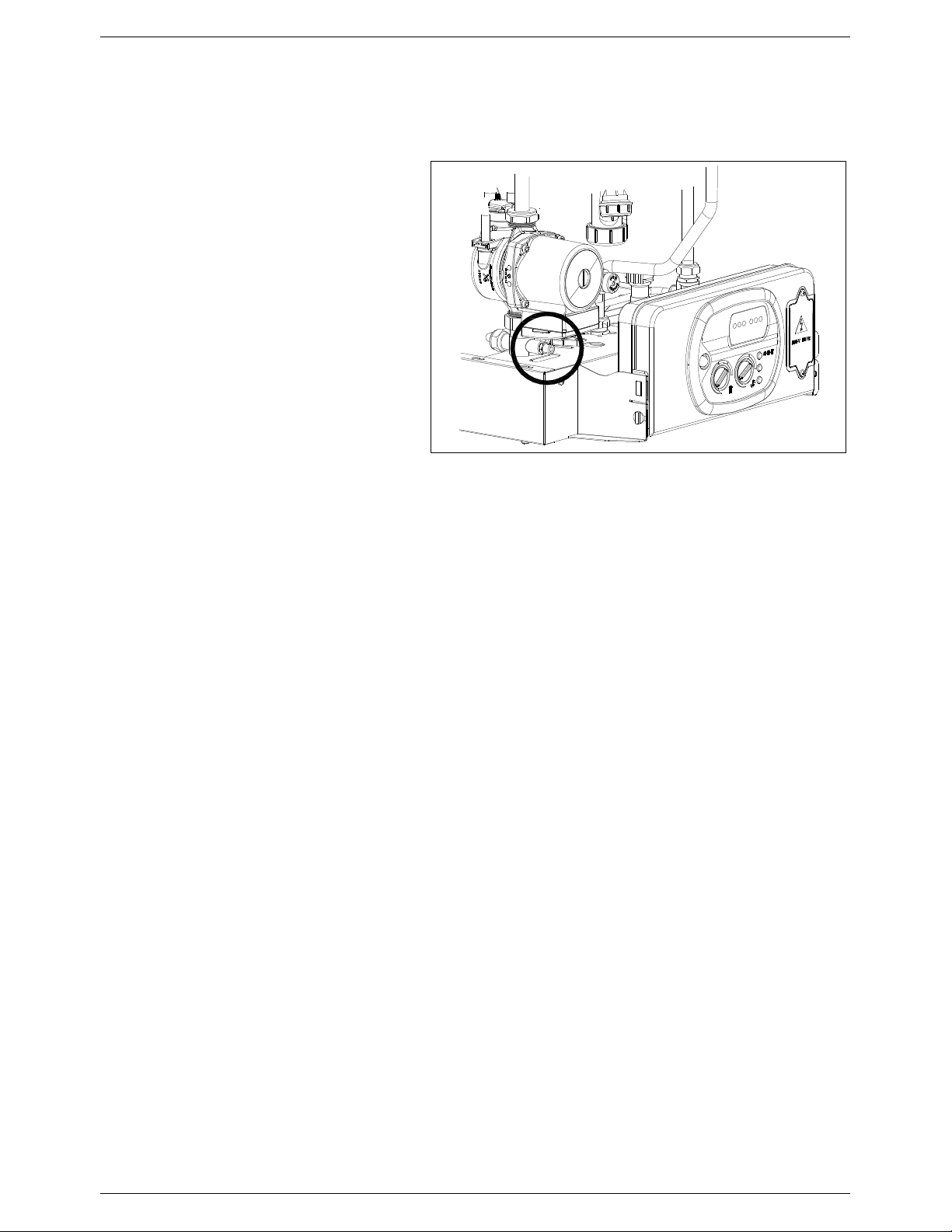
• Open the boiler drain valve, located on the
bottom of the pump manifold (see Figure
36);
• Open the air vents on the radiators, starting
with the highest and moving down the
system to the lowest;
• W hen the system has been drained, close
the radiator air vents and the boiler drain
valve.
Figure 36: Boiler drain valve
If ONLY THE BOILER needs to be drained:
• Switch on the boiler, select Heating Only Mode and allow the boiler to fire. Refer to Section 3.6 for how to
operate the appliance;
• Isolate the electricity and gas supplies to the boiler and wait for the boiler to cool down;
• Close the isolating valves on the heating circuit flow and return pipes;
• Connect a hosepipe to the system drain point and locate the other end of the hose in a suitable drain;
• Open the drain valve located at the bottom of the boiler on the pump manifold (see Figure 36);
6.5 Flushing the central heating system
Refer to the detailed instructions in Section 5.3.
TR05A140.B1107
45
Page 48
MAINTENANCE INSTRUCTIONS
6.6 Maintenance operations
Before carrying out any cleaning or part replacement operations, ALWAYS turn off the ELECTRICITY,
WATER and GAS supplies to the boiler. Warmflow will not be held responsible for damage to any of
the boiler’s components caused by non-compliance with this instruction.
Section 6.3 gives instructions on accessing the boiler, removing casing panels, and accessing the control panel.
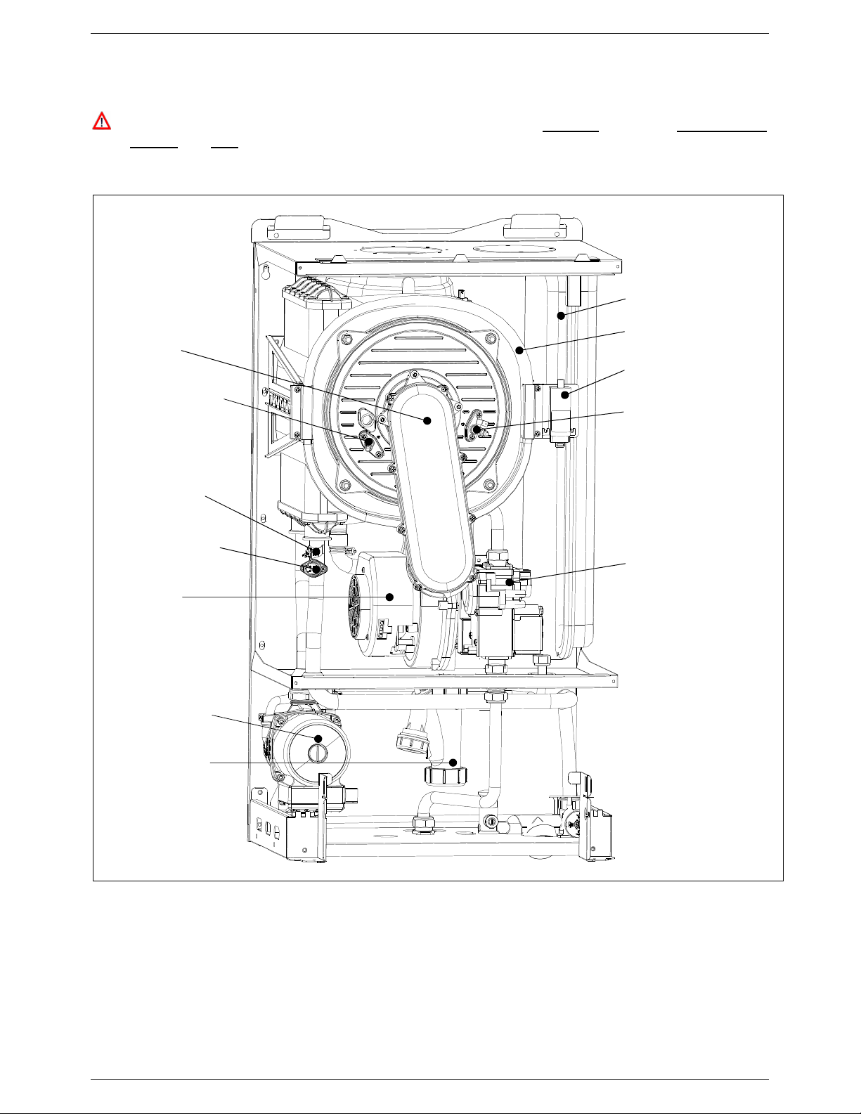
Expansion vessel
Primary heat exchanger
Burner unit
Ignition transformer
Ionisation electrode
Heating sensor
Safety thermostat
Electric fan
Circulating pump
Condensate trap
Ignition electrode
Gas valve
Figure 37: Key components
TR05A140.B1107
46
Page 49
MAINTENANCE INSTRUCTIONS
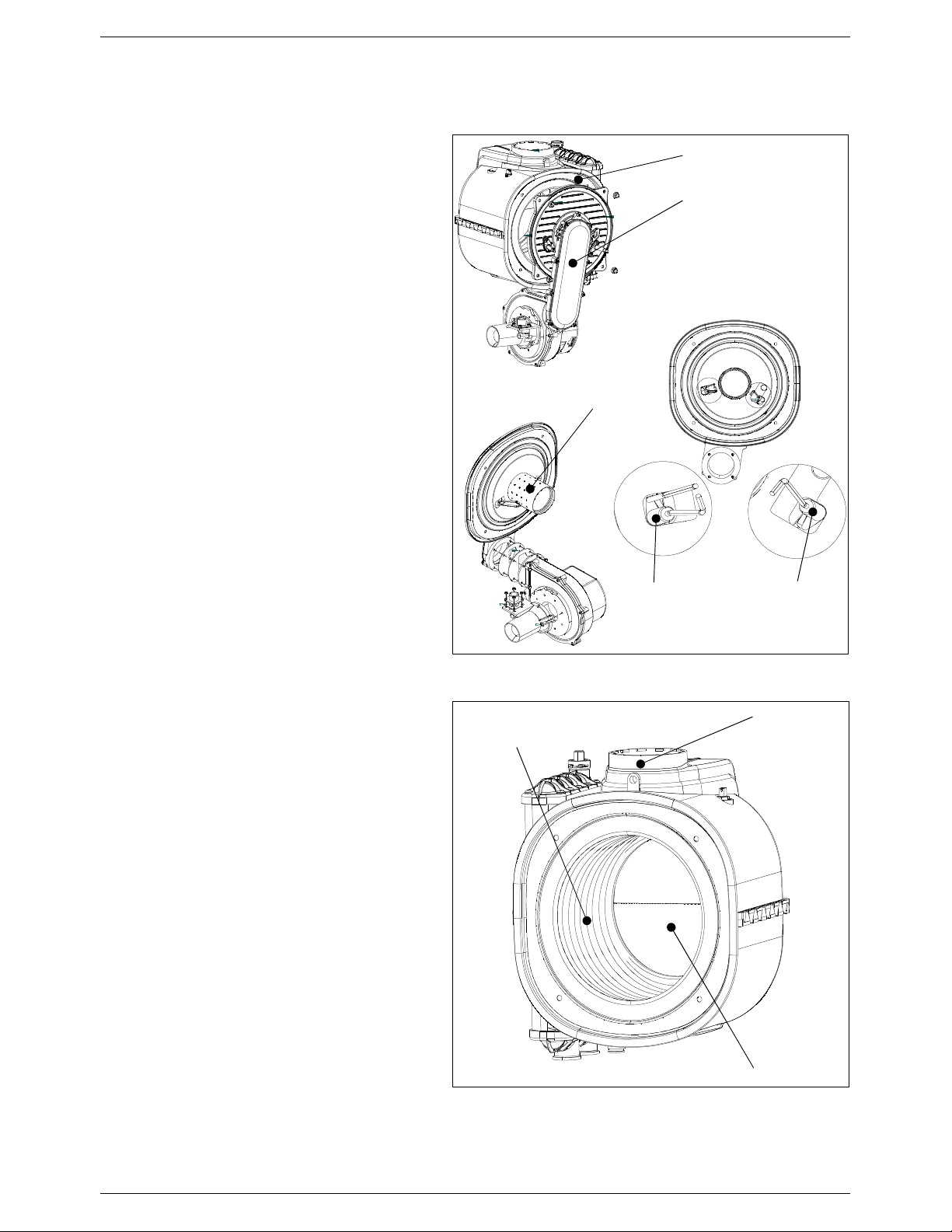
6.6.1 Primary heat exchanger and burner unit
• Isolate the electricity, water and gas supplies to
the appliance;
• Disconnect the electrical connections of the
electric fan;
• Disconnect and remove the pipe linking the gas
valve to the venturi;
• Disconnect and remove the gas feed pipe from
the gas valve;
• Unplug the ignition and ionisation electrode
wires from the ignition control unit;
• Unscrew the ring nut at the bottom of the room
sealed chamber and remove the gas valve;
• Unscrew the nuts securing the burner unit
(consisting of a fan, manifold and burner) to the
primary heat exchanger;
• Remove the burner unit, taking particular care
not to remove the ceramic fibre board from the
end of the heat exchanger;
• Check that the burner is not affected by
deposits, scaling or excessive oxidation. Check
that all the holes in the burner are free;
• Clean the electrodes carefully without altering
their positions with respect to the burner;
• Clean the burner cylinder using a non-metal
brush and without damaging the ceramic fibre;
• Check the integrity of the seal on the cover of
the burner;
• Clean the heat exchanger using a suitable
detergent for stainless steel, distributing the
product on the spirals of the exchanger using a
brush. Do not wet the ceramic fibre board. Wait
a few minutes then remove the deposits using a
non-metal brush. Remove the residues under
running water;
• Remove the condensate drain pipe and clean
under running water;
• Unscrew the joint to the condensate trap,
remove the trap and wash under running water;
• With the cleaning completed, re-assemble the
components following the above procedure in
reverse order;
• Finally, check the boiler to make sure that all
gas and exhaust joints are tight.
Figure 38: Primary heat exchanger and burner unit
Stainless steel
exchanger coils
Burner
Ignition
electrode
Primary heat exchanger
Premix burner unit
B
A
Ionisation
electrode
Flue manifold
Ceramic fibre
Figure 39: Primary heat exchanger
TR05A140.B1107
47
Page 50
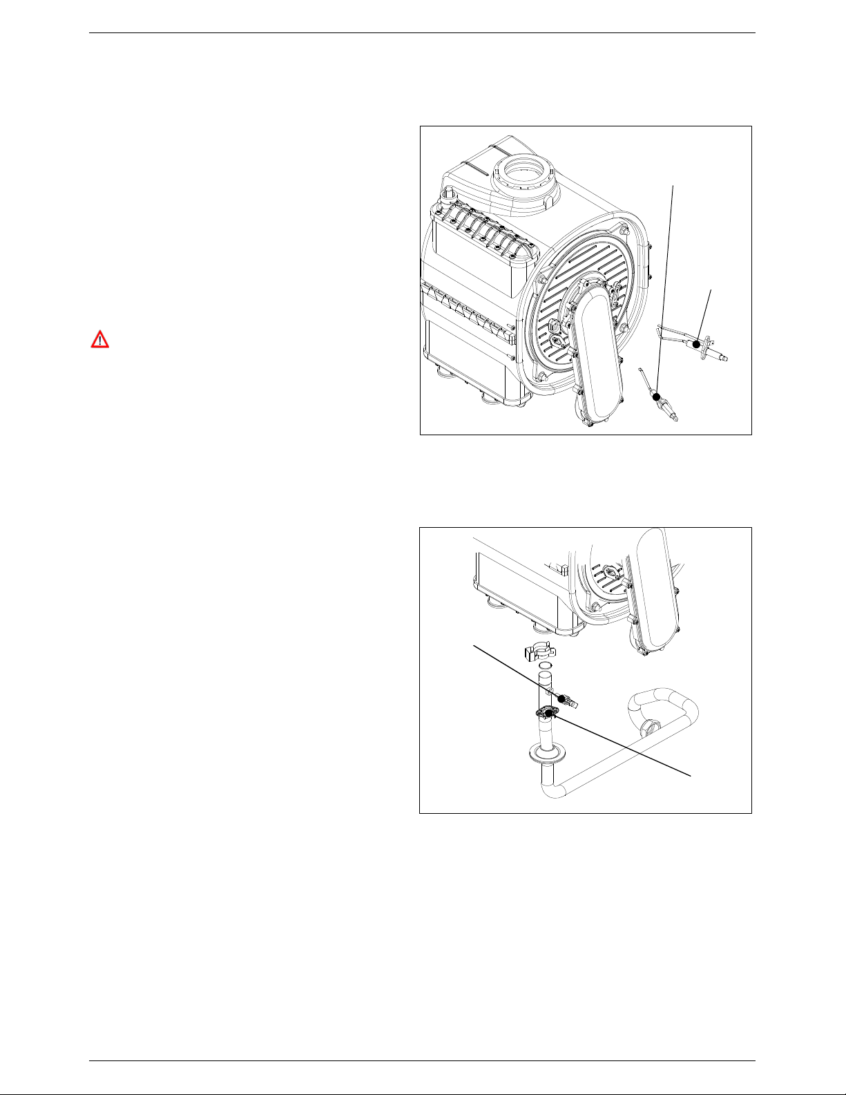
MAINTENANCE INSTRUCTIONS
Figure
42
: Safety thermostat and heating sensor
6.6.2 Ignition and ionisation electrodes
• Isolate the electricity, water and gas supplies to the
appliance;
• Unplug the electrode wires;
• Slacken the fixing screws;
• Remove the electrodes. When refitting the
electrodes, check that the seals are not damaged
and replace if necessary;
• Reconnect the wires and reassemble the
components following the above procedure in
reverse order;
• Switch on the power supply and restart the
appliance;
If the boiler does not restart, check the
positions of the electrodes. The ignition
electrode should be positioned with a 10mm
gap between it and the burner. The ionisation
electrode must not be touching the burner
surface.
Ionisation
electrode
Ignition
electrode
6.6.3 Safety thermostat
• Isolate the electricity, water and gas supplies to the
appliance;
• Disconnect the connecting wire;
• Unscrew the fixing screws and remove the
thermostat;
• Replace the thermostat and re-assemble the
components following the above procedure in
reverse order;
6.6.4 Heating sensor
• Isolate the electricity, water and gas supplies to the
appliance;
• Unplug the connecting wires;
• Replace the sensor (expecting some water loss)
and reconnect the wires;
• Refill the system (see Sections 5.2) and check for
any leaks.
Figure 41: Ignition and ionisation electrodes
Heating sensor
Safety thermostat
TR05A140.B1107
48
Page 51
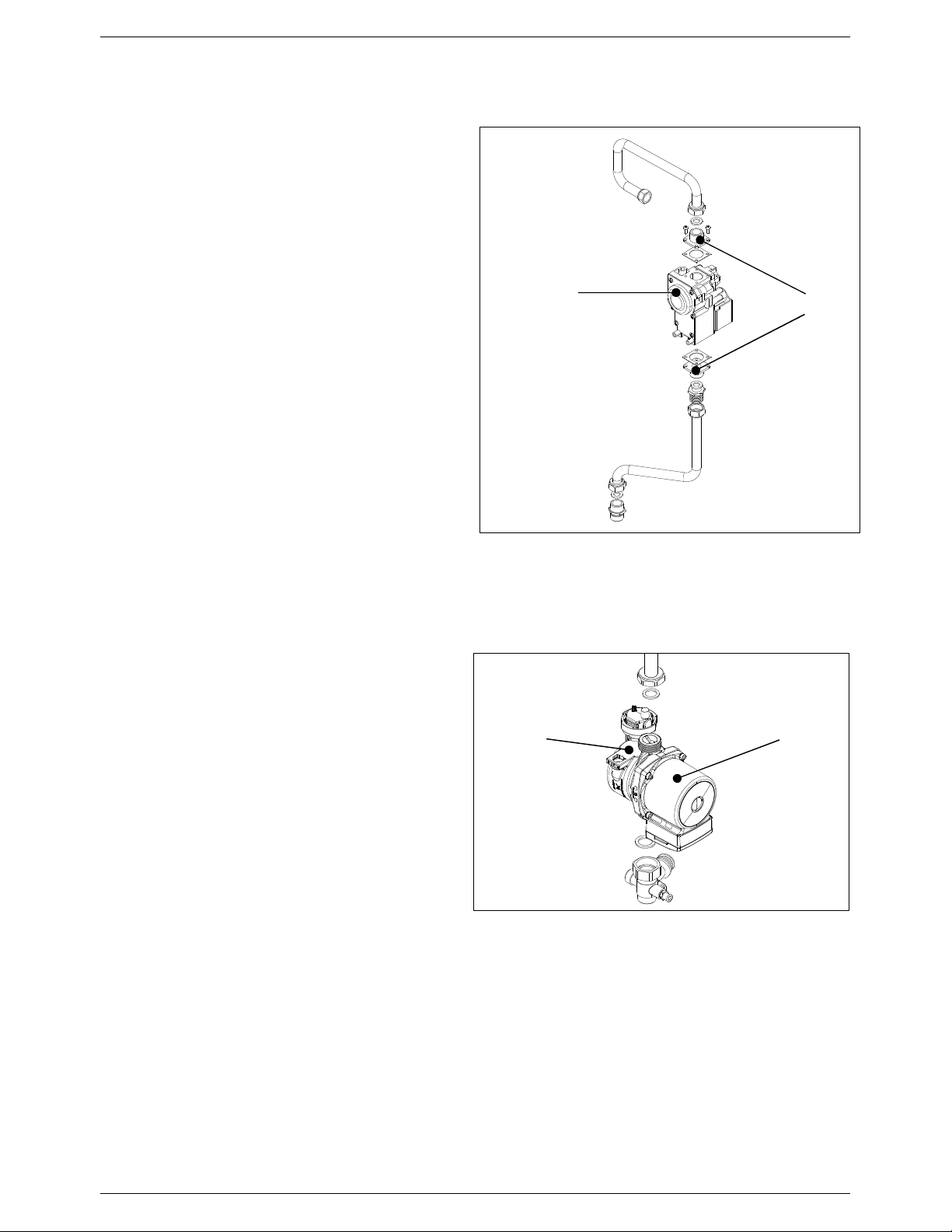
MAINTENANCE INSTRUCTIONS
6.6.5 Gas valve
• Isolate the electricity, water and gas supplies to the
appliance;
• Disconnect and remove the gas pipe connecting the
gas valve to the venturi;
• Disconnect the gas feed pipe and valve ring nut at
the bottom of the room sealed chamber;
• Remove the couplings of the existing valve and fit to
the new valve using new cork gaskets;
• Replace the gas valve and reassemble the
components following the above procedure in
reverse order, replacing all the gas seals;
• Switch on the gas supply and check for any gas
leaks using soapy water or leak detector spray;
• Switch on the electricity and water supplies, switch
on and fire the appliance and repeat the checks for
leaks.
Gas valve
Couplings
6.6.6 Circulating pump motor body
• Isolate the electricity, water and gas supplies to the
appliance;
• Drain the central heating circuit of the boiler (see
Section 6.4);
• Use a 5 mm Allen key to unscrew the four screws
securing the motor body to the impeller body;
• Remove the motor body and check the condition of
the gasket. Replace if necessary;
• Replace the pump motor body and reassemble the
components following the above procedure in
reverse order;
• Switch on the electricity, water and gas supplies;
• Refill the system (see Sections 5.2) and check for
any leaks.
Figure 43: Gas valve
Pump impeller body
Figure 44: Circulating pump
Pump motor body
TR05A140.B1107
49
Page 52
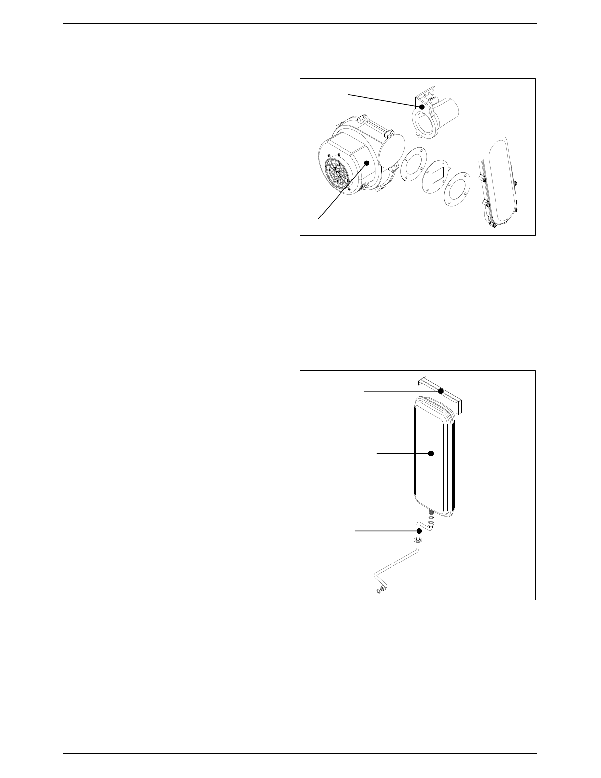
MAINTENANCE INSTRUCTIONS
6.6.7 Electric fan
• Isolate the electricity, water and gas supplies to the
appliance;
• Remove and dismantle the entire burner unit (see
Section 6.6.1);
• Use an 8 mm spanner to unscrew the four nuts
securing the electric fan to the gas manifold and
then remove the electric fan, noting the positions of
the washer and diaphragm (see Figure 45);
• Remove the air intake duct, unscrew the two fixing
screws from the venturi and remove the electric fan,
paying particular attention not to damage the cork
gasket.
• Replace the electric fan and reassemble the
components following the above procedure in
reverse order.
• Switch on the electricity, water and gas supplies and
check the soundness of the joint by measuring the CO2 levels;
Figure 45: Fan assembly
Venturi
Fan
6.6.8 Expansion vessel
• Isolate the electricity, water and gas supplies to the
appliance;
• Drain the central heating circuit of the boiler (see
Section 6.4);
• Use a 19 mm spanner to unscrew the vessel pipe
coupling;
• Unscrew the fixing screws and remove the upper
mounting bracket. Remove the expansion vessel
from the front of the boiler;
• Replace the expansion vessel and reassemble the
components following the above procedure in
reverse order;
• Switch on the electricity, water and gas supplies;
• Refill the system (see Sections 5.2) and check for
any leaks.
Fixing bracket
Expansion vessel
Vessel pipe
Figure 46: Expansion vessel
TR05A140.B1107
50
Page 53
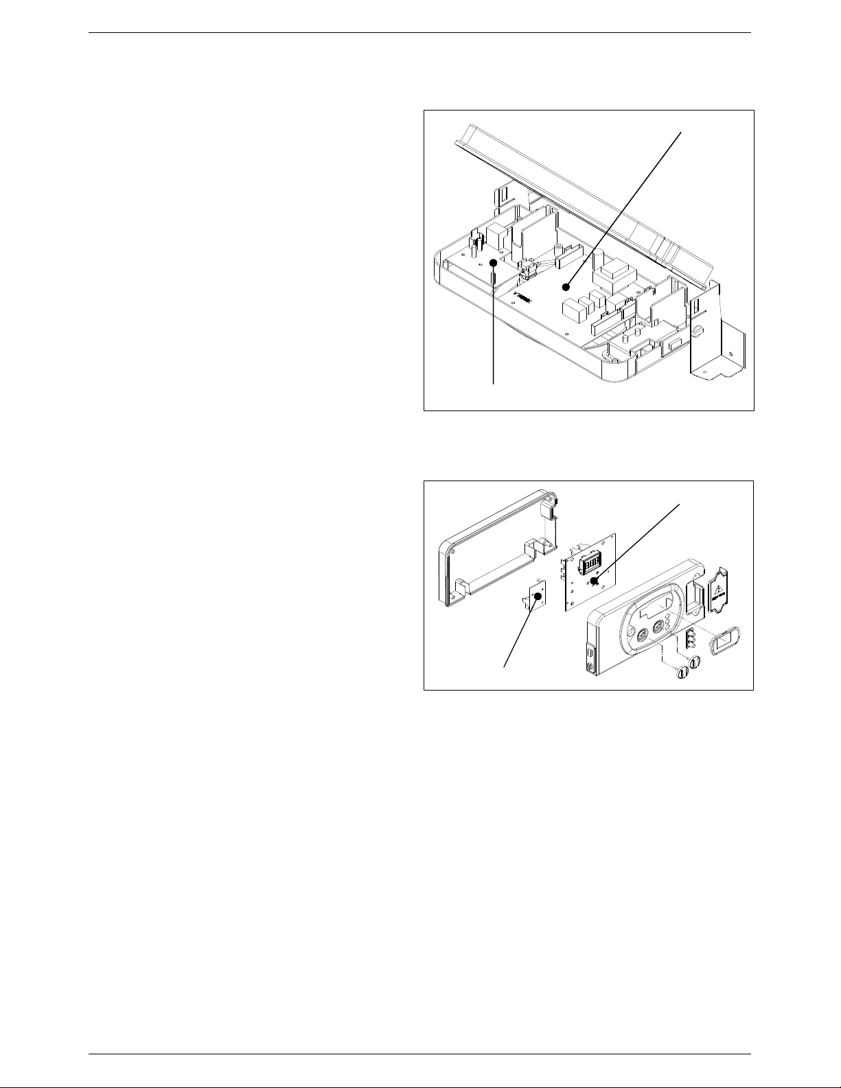
Figure
49
: Circuit boards
6.6.9 Modulation circuit board
MAINTENANCE INSTRUCTIONS
• Isolate the electricity, water and gas supplies to the
appliance;
• Access the control panel (see Section 6.3);
• Disconnect all the connectors, remove the control
knobs from the front of the panel, unscrew the fixing
screws and remove the modulation circuit board;
• Replace the circuit board and reassemble the
components following the above procedure in
reverse order;
• Switch on the electricity, water and gas supplies;
• Program the boiler control parameters following the
instructions in Sections 5.7.
6.6.10 Electric fan circuit board
• Isolate the electricity, water and gas supplies to the
appliance;
• Access the control panel (see Section 6.3);
• Disconnect the two connectors from the fan circuit
board, unscrew the two fixing screws and remove the
board;
• Replace the circuit board and reassemble the
components following the above procedure in
reverse order.
Modulation circuit board
Electric fan circuit board
Modulation circuit board
Electric fan circuit board
Figure 50: Circuit boards
6.6.11 Primary heat exchanger replacement
• Isolate the electricity, water and gas supplies to the appliance;
• Drain the central heating circuit of the boiler (see Section 6.4);
• Remove and dismantle the entire burner unit (see Section 6.6.1);
• Remove the gas valve (see Section 6.6.5);
• Remove the condensate drainpipe;
• Remove the flow and return pipe work;
• Remove the support brackets and pull out the heat exchanger;
• Remove the sensors and pipes from the old exchanger and fit them to the new one;
• Replace the heat exchanger and reassemble the components following the above procedure in reverse order;
• Switch on the electricity, water and gas supplies;
• Refill the system (see Sections 5.2) and check for any leaks;
• Fire the boiler and check for any flue gas leaks.
TR05A140.B1107
51
Page 54
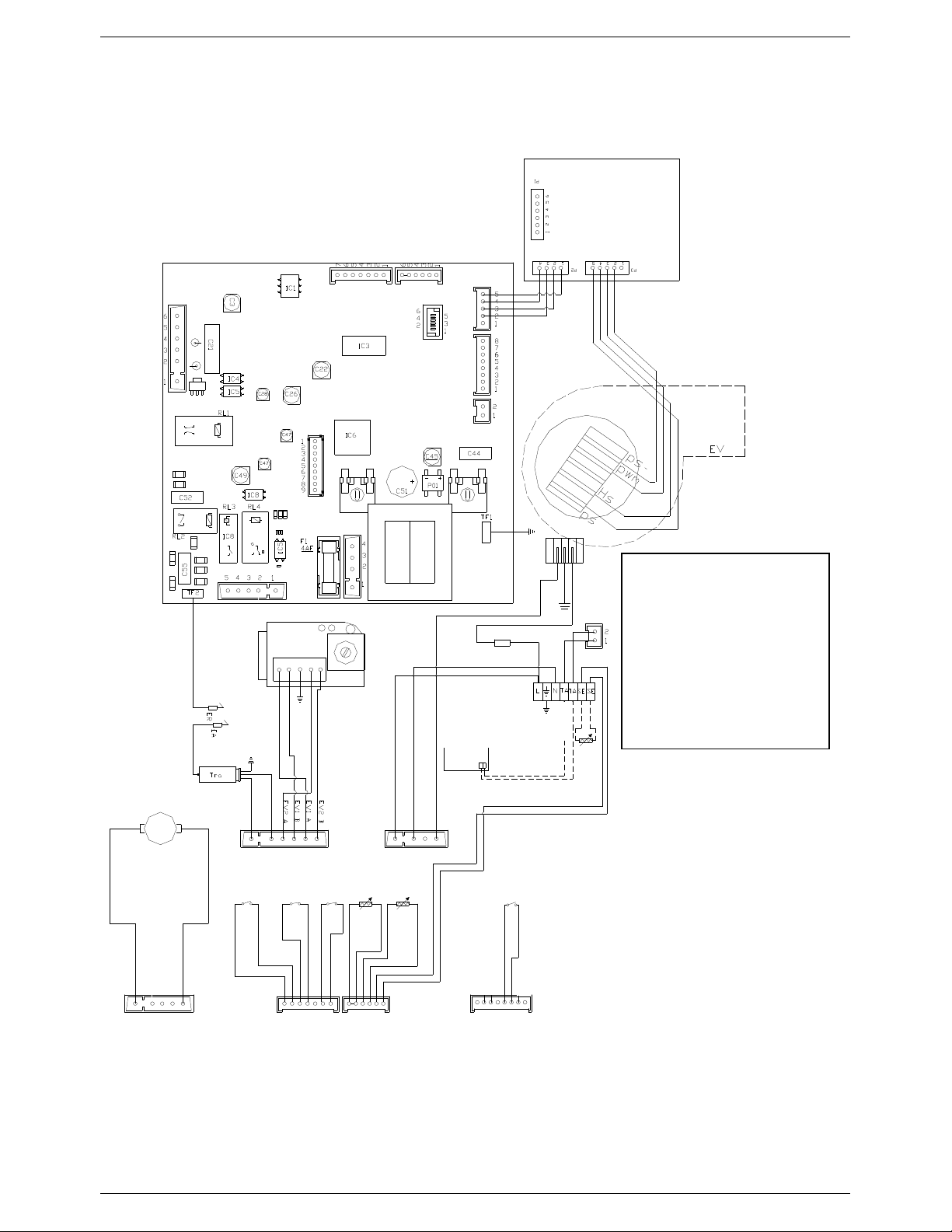
6.7 Wiring diagram
PRINTED CIRCUIT BOARD DIGITECH - SM20019
COD. 16766077
M5
MAINTENANCE INSTRUCTIONS
PRINTED CIRCUIT BOARD
KOND DT - SK11003
COD. 18767002
M2M1
M3
M4
M6
M7
EXHAUST FAN
type RG128/1300-3612
M8
POWER SUPPLY
M9
M10
N
+
yellow/green
L
Key
IG Main Switch
PA Air Pressure switch
TS Safety thermostat
CVI-M
EV2
EV1
red
orange
light-blue
brown
light-blue
brown
C
1
2 3 4 5 6
TF
light-blue
orange
orange
brown
light-blue
brown
VK 4105 G
Telephone control
EXTERNAL
CONTROLS
Remote control
light-blue
M5
1
4
3
2
TS
light-blue
brown
10000 OhmSRIG
black
white/black
orange
orange
M9
light-blue
brown
Storage cylinder timer
(option)
fusibile 2A
brown
black
black
SE
Zone valve management +
option remote controller board
Pacq
brown
light-blue
TF Thermofuse 102°C
SR Heating sensor
M7
EV Fan
ER Ionisation electrode
EA Ignition electrode
Tra Ignition transformer
C Circulating pump
Pacq Water pressure switch
remote controller
zone valve
Zone valve
contact closure
M10
5
321
4
M1
M2
1234561234567
123456678
M4M6
Figure 51: Internal wiring
TR05A140.B1107
52
Page 55
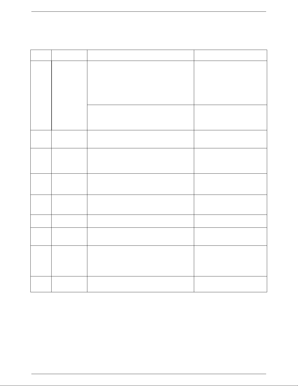
MAINTENANCE INSTRUCTIONS
6.8 Troubleshooting
6.8.1 Error codes
CODE PROBLEM POSSIBLE CAUSE REMEDY
IF BOILER FAILS TO FIRE
a. CHECK MAINS SUPPLY
b. CHECK INLET PRESSURE
c. CHECK AND ADJUST MECHANICAL
MINIMUM AND IGNITION
SEQUENCE SETTINGS
d. REPLACE PART
e. REPLACE PART
f. CORRECT MAINS WIRING
g. CHECK ELECTRODE WIRING
h. REPLACE PART
E01
NO FLAME
(FLAME FAILURE
DURING STARTUP)
a. NO GAS
b. GAS INLET PRESSURE TOO HIGH
c. MECHANICAL MINIMUM OR IGNITION SEQUENCE
GAS PRESSURES TOO LOW
d. IGNITION ELECTRODE BROKEN OR EARTHED
e. GAS VALVE MALFUNCTION
IF BOILER FIRES NORMALLY
f. MAINS LIVE AND NEUTRAL WIRES REVERSED
g. IONISATION ELECTRODE CABLE DISCONNECTED
h. IONISATION ELECTRODE MALFUNCTION
E02
E03
H20
E05
E16
E22
E35
SAFETY
THERMOSTAT
TRIPPED (95°C)
FLUE
THERMOFUSE
TRIPPED
LOW SYSTEM
PRESSURE
HEATING
SENSOR FAULT
FAN FAULT
PARAMETER
PROGRAMMING
REQUEST
IONISATION
ELECTORDE
FAULT
a. THERMOSTAT CABLE DISCONNECTED
b. THERMOSTAT MALFUNCTION
a. THERMOFUSE CABLE DISCONNECTED
b. THERMOFUSE LOCK OUT (DUE TO HIGH FLUE
TEMPERATURE)
c. THERMOFUSE MALFUNCTION
a. WATER PRESSURE SWITCH CABLE DISCONNECTED
b. INSUFFICIENT WATER PRESSURE IN THE SYSTEM
c. WATER PRESSURE SWITCH MALFUNCTION
a. SENSOR CABLE DISCONNECTED OR WET
b. SENSOR MALFUNCTION OR OUT OF CALIBRATION
(RESISTANCE VALUE 10 kOhms AT 25 °C).
a. CHECK THERMOSTAT WIRING
b. REPLACE PART
a. CHECK THERMOSTAT WIRING
b. REPLACE THERMOSFUSE,
RESTART AND CHECK APPLIANCE
c. REPLACE PART
a. CHECK SWITCH WIRING
b. FILL OR TOP UP THE SYSTEM
c. REPLACE PART
a. CHECK SENSOR WIRING
b. CHECK SENSOR RESISTANCE.
REPLACE IF INCORRECT
a. BURNT FAN a. REPLACE PART
a. LOSS OF MICROPROCESSOR MEMORY a. REPROGRAM PARAMETERS
a. IONISATION ELECTRODE WET, DAMP OR EARTHED
b. IONISATION ELECTRODE MALFUNCTION
c. IONISATION ELECTRODE CABLE MALFUNCTION
d. MODULATION PCB MALFUNCTION
a. CHECK COMBUSTION CHAMBER
b. CLEAN PART (REPLACE IF FAULT
REMAINS AFTER CLEANING)
c. REPLACE PART
d. REPLACE PART
E42
FAN PCB FAULT
a. FAN PCB TO MOD. PCB WIRING MALFUNCTION
b. FAN PCB MALFUNCTION
a. REPLACE PART
b. REPLACE PART
Table 10: Appliance error codes
TR05A140.B1107
53
Page 56

MAINTENANCE INSTRUCTIONS
6.9 Parts lists
6.9.1 Main components
CODE DESCRIPTION
40200069 PRIMARY EXCHANGER ISOTHERM. 4+1 3+3 25KW
12240045 PUMP RSL 15/5-3-KU-CLF6 w/OPEN C1+C3
46270044 CONDENSATE TRAP
50360067 ELECTRONIC GAS VALVE
40360068 VENTURI
20370032 FAN PX128/203 230V/50Hz - PX2030
28432074 WASHER/OR CLIPS KIT FOR MULTIPLEX
28590015 WATER PRESSURE SWITCH PC 5411 BRASS
40735016 HTG CLIP SENSOR X PIPE 17/18 mm. BLUE
40735017 THERMO FUSE 102°C RED ISTMQ 1/4" 4X45
16766077 PRINTED CIRCUIT BOARD BMBC c/DISPLAY
18767002 PRINTED CIRCUIT BOARD KOND DT
44860006 SAFETY THERMOSTAT 95C° X EL.TB 1NT
28860014 WATER PRESSURE GAUGE M3A-ABS 40 0-4 G1/8C/D+C
18880019 TRANSFORMER AC1 230VAC 25HZ 39/3200Y
48950013 EXPANSION VESSEL LT.7 3/8"
12960039 3 BAR PRESSURE RELIEF VALVE -HTG CIRCUIT
Table 11: Short parts list
TR05A140.B1107
54
Page 57
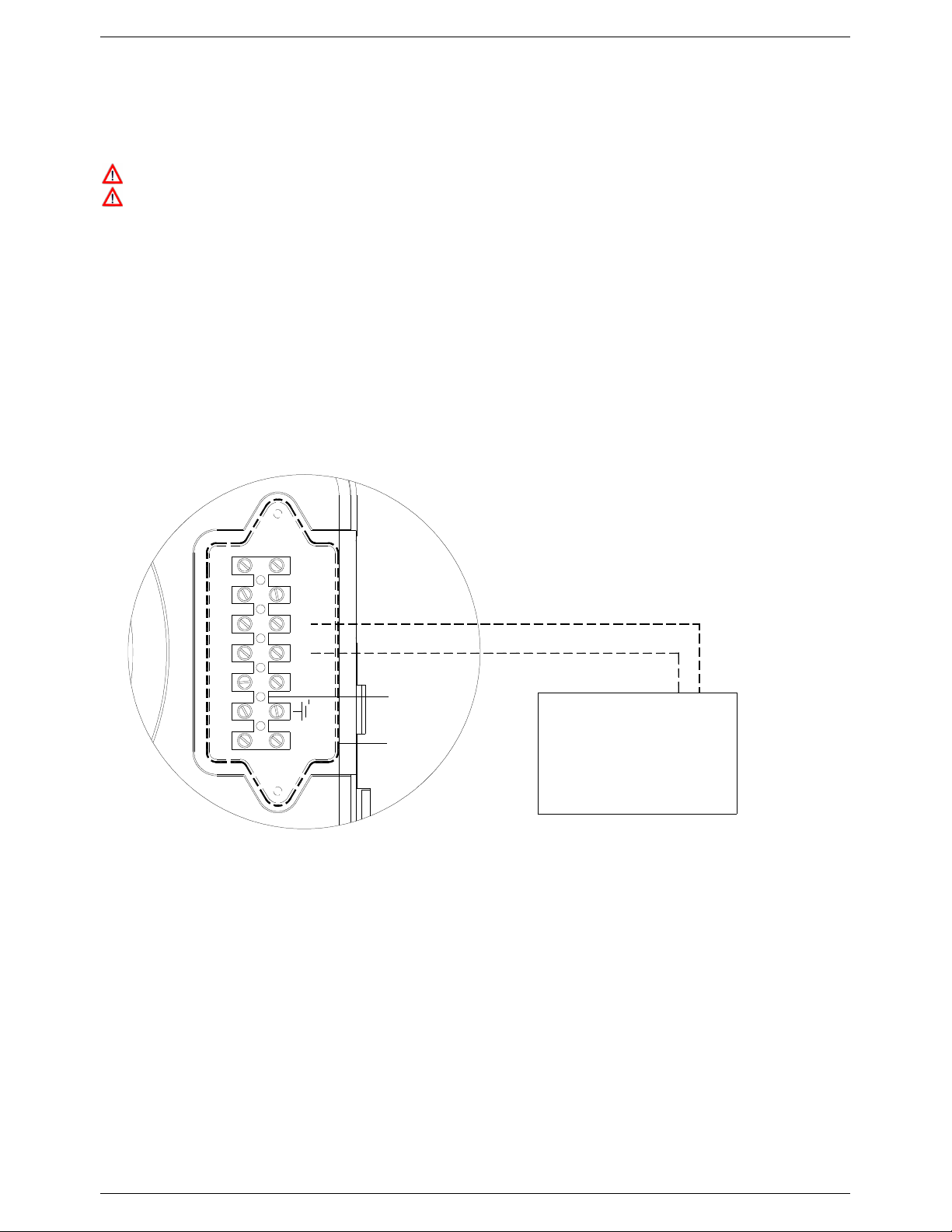
OPTIONAL CONTROLS
7 OPTIONAL CONTROLS
7.1 External controls, programmers and room thermostats
All external controls used with this appliance MUST BE ZERO-VOLT SWITCHING ONLY!
If mains voltage, i.e. a switched live, is fed to the control terminals THE APPLIANCE WILL NOT
FUNCTION and could be SEVERELY DAMAGED!
7.1.1 Appliance connections
To fit a programmer, room thermostat or other external controls:
• Isolate the electricity, water and gas supplies to the appliance;
• Remove the front casing panel of the boiler (refer to 6.3 for guidance);
• Remove terminal block cover A of the control panel;
• Remove the link between the two terminals marked Ta on terminal block B;
• Connect the two wires from the programmer, room thermostat or controls to the terminals marked Ta;
• Replace terminal block cover A.
SeSeTaNL
Ta
Figure 52: Connection of external controls
B
A
External Controls:
- Programmer
- Room thermostat
- S-Plan system
TR05A140.B1107
55
Page 58
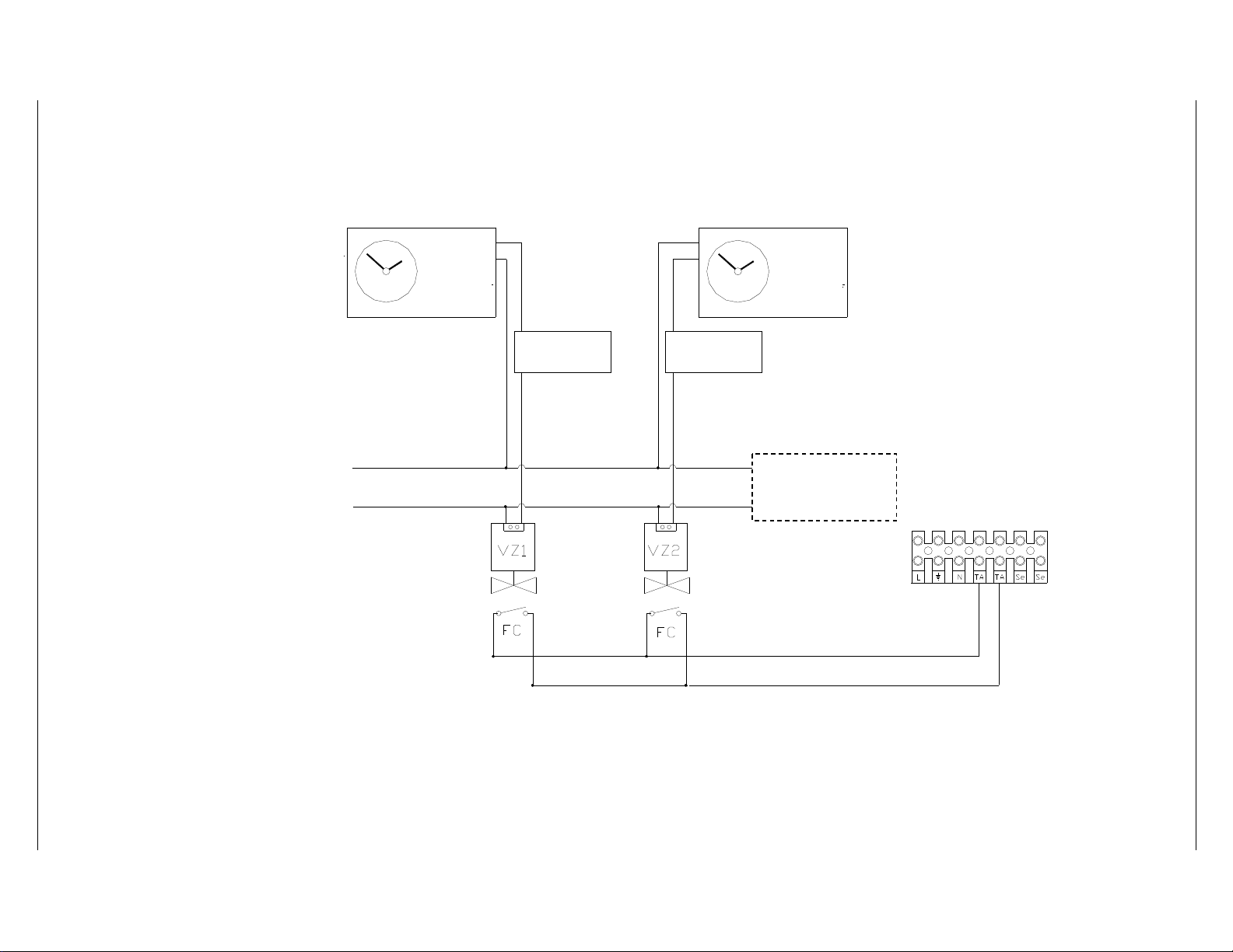
TR05A140.B1107
Figure 53: S-Plan wiring schematic
7.1.2 S-Plan wiring schematic
Heating Zone Hot Water Cylinder
Room
Thermostat
56
Permanent Live
Cylinder
Thermostat
OPTIONAL CONTROLS
Add more valves
& programmers
Neutral
as required
Boiler
Terminal Block
2-port
zone valves
Zone valve
microswitches
Zero-volt Switching Circuit
Page 59

THIS PAGE IS INTENTIONALLY BLANK
THIS PAGE IS INTENTIONALLY BLANK
Page 60

THIS PAGE IS INTENTIONALLY BLANK
THIS PAGE IS INTENTIONALLY BLANK
Page 61
INSTALLATION, COMMISSIONING & SERVICING RECORD
INSTALLER & COMMISSIONING ENGINEER DETAILS
Installer Details
Company Name Installation Date
Address
CORGI Registration No. CORGI ID Serial No.
Commissioning Engineer Details (if different from Installer)
Company Name Installation Date
Address
CORGI Registration No. CORGI ID Serial No.
APPLIANCE & CONTROL DETAILS
Boiler
Make & Model
Serial No. SEDBUK Efficiency
Location
New System or Replacement boiler
Controls
To comply with Building Regulations, each section must have a tick in one or more boxes
Requirement Measures Provided
1. Time and Temperature Control to Heating
2. Time and Temperature Control to Hot Water
3. Heating Zone Valves Fitted Not Required
4. Thermostatic Radiator Valves Fitted
5. Automatic Bypass to System Fitted Not Required
Room Thermostat and
Programmer / Timer
Cylinder Thermostat and
Programmer / Timer
Programmable Room
Thermostat
Combi Boiler
%
6. Boiler Interlock Provided
TR05A140.B1107
Page 62
INSTALLATION, COMMISSIONING & SERVICING RECORD
COMMISSIONING PROCEDURE INFORMATION
For All Boilers
Has the system been flushed in accordance with the boiler manufacturer’s instructions? Yes No
What cleanser was used?
Has an inhibitor been added? Yes No
Which inhibitor was used?
For central heating mode, measure and record:
Heat Input kW
Burner Operating Pressure mbar
Central Heating Flow Temperature ºC
Central Heating Return Temperature ºC
For Combination Boilers Only
Has a water scale reducer been fitted? Yes No
What type of scale reducer has been fitted?
For domestic hot water mode, measure and record:
Heat Input kW
Maximum Burner Operating Pressure mbar
Maximum Operating Water Pressure bar
Cold Water Inlet Temperature ºC
Hot Water Outlet Temperature ºC
Water Flow Rate at Maximum Setting l/min
For Condensing Boilers Only
Has the condensate drain been fitted in accordance with the manufacturer’s instructions? Yes No
For All Installations
Does the heating and hot water system comply with the appropriate Building Regulations? Yes
Has the appliance and associated equipment been installed and commissioned in accordance with
the manufacturer’s instructions?
Have you demonstrated the operation of the appliance and system controls to the customer? Yes
Have you left all the manufacturer’s literature with the customer? Yes
Competent Person’s Signature Customer’s Signature
TR05A140.B1107
(To confirm demonstrations of equipment and receipt of
appliance instructions)
Yes
Page 63
INSTALLATION, COMMISSIONING & SERVICING RECORD
Service 1 Date: Service 2 Date:
Engineer Name Engineer Name
Company Name Company Name
Tel. No. Tel. No.
CORGI ID Serial No. CORGI ID Serial No.
Comments Comments
Signature
Service 3 Date: Service 4 Date:
Engineer Name Engineer Name
Company Name Company Name
Tel. No. Tel. No.
CORGI ID Serial No. CORGI ID Serial No.
Comments Comments
Signature
Service 5 Date: Service 6 Date:
Engineer Name Engineer Name
Company Name Company Name
Tel. No. Tel. No.
CORGI ID Serial No. CORGI ID Serial No.
Comments Comments
Signature
Service 7 Date: Service 8 Date:
Engineer Name Engineer Name
Company Name Company Name
Tel. No. Tel. No.
CORGI ID Serial No. CORGI ID Serial No.
Comments Comments
Signature
Service 9 Date: Service 10 Date:
Engineer Name Engineer Name
Company Name Company Name
Tel. No. Tel. No.
CORGI ID Serial No. CORGI ID Serial No.
Comments Comments
Signature
Signature
Signature
Signature
Signature
Signature
TR05A140.B1107
Page 64

THIS PAGE IS INTENTIONALLY BLANK
THIS PAGE IS INTENTIONALLY BLANK
Page 65

THIS PAGE IS INTENTIONALLY BLANK
THIS PAGE IS INTENTIONALLY BLANK
Page 66

WARMFLOW Engineering Company Limited
Lissue Industrial Estate, Moira Road, Lisburn BT28 2RF
Tel: 028 9262 1515 Fax: 028 9262 0869
Warmflow Customer Care Centre
THE TECHNICAL DATA AND MEASUREMENTS ARE PROVIDED FOR
INFORMATION PURPOSES ONLY AND ARE NOT BINDING. THE COMPANY
RESERVES THE RI GHT TO APPLY VARIATIONS WI THOUT PRIOR NOTIFICATION.
NEITHER WILL THE COMPANY BE HELD RESPONSIBLE FOR ANY INACCURACIES
IN THIS HANDBOOK DERIVING FROM PRINTI NG OR TRANSLATION ERRORS.
E+OEALL RIGHTS RESERVED. NO PART OF THIS DOCUMENT MAY BE
REPRODUCED, MEMORISED IN ANY FILING SYSTEMS OR TRANSMITTED IN ANY
FORM WHATSOEVER, INCLUDING ELECTRONIC, MECHANICAL, PHOTOCOPIES,
RECORDINGS OR ANY OTHER MEANS W ITHOUT THE COMPANY’S PRIOR
WRITTEN APPROVAL.
TR05A140.B1107
 Loading...