

WarmFlow Direct DI250UV, Direct DI90UV, Direct DI150UV, Indirect IN120UV, Direct DI300UV User Instructions
...
Cylinder Manual
Direct
DI90UV
DI120UV
DI150UV
DI180UV
DI210UV
DI250UV
DI300UV
Indirect
IN120UV
IN150UV
IN180UV
IN210UV
IN250UV
IN300UV
Eco Direct
ED180UV
ED210UV
ED250UV
ED300UV
Twin Coil
TW180UV
TW210UV
TW250UV
TW300UV
Triple Coil
TR250UV
TR300UV
Incorporating: User Instructions
Installation Instructions
Commissioning Instructions
Maintenance Instructions
Unvented Cylinders
Mains pressure water heaters
EN 12897:2006
Products covered by this manual:
LEAVE THIS MANUAL WITH THE END USER

INSTALLATION, COMMISSIONING & SERVICING
This appliance must be installed as described herein and the installation commissioned by
competent persons as instructed. The Guarantee Registration section of the separate Cylinder
Passport supplied with the product must be completed and the Guarantee Registration only
returned to the manufacturer with proof of purchase (e.g. receipts / invoices).
This appliance must be serviced annually by competent persons, the Service Record section of
the separate Cylinder Passport completed on each occasion and proof of servicing (e.g.
receipts / invoices) retained.
The complete guarantee policy statement is included in Section 9, page 21.
FAILURE TO COMMISSION, REGISTER AND ANNUALLY SERVICE THIS
PRODUCT WILL INVALIDATE ALL GUARANTEES
TECHNICAL, SPARES & GUARANTEE CLAIMS
For technical advice about the installation, commissioning, servicing or use of this appliance,
please contact the Warmflow Customer Care Centre by post, phone, fax or email at the
addresses below. Please also refer to our website.
Should replacement components be required, a list of available spares is provided in Section
8.3, page 19.
In the unlikely event that replacement components might be required within the guarantee
period, please notify the Customer Care Centre in writing, by post, fax or email, stating the
nature of the fault and the part number of the replacement components required.
Warmflow Customer Care Centre
Warmflow Engineering
Lissue Industrial Estate
Moira Road
Lisburn
BT28 2RF
Northern Ireland
Telephone
United Kingdom: 028 9262 1515
Republic of Ireland: 048 9262 1515
Facsimile
United Kingdom: 028 9262 0869
Republic of Ireland: 048 9262 0869
Email
technical@warmflow.co.uk
Website
www.warmflow.co.uk

CONTENTS
1 User Instructions ................................................................................................................. 2
1.1 Cylinder Thermostat ................................................................................................................... 2
1.2 Immersion Thermostat ............................................................................................................... 2
1.3 Discharge ................................................................................................................................ ... 2
2 Installation Requirements ................................................................................................... 3
3 Handling and Storage ......................................................................................................... 4
4 Standard Equipment ........................................................................................................... 4
5 Technical Data ..................................................................................................................... 4
5.1 General ...................................................................................................................................... 4
5.2 Direct Cylinders .......................................................................................................................... 5
5.3 Indirect Cylinders........................................................................................................................ 6
5.4 Eco Direct Cylinders ................................................................................................................... 7
5.5 Twin Coil Cylinders ..................................................................................................................... 8
5.6 Triple Coil Cylinders ................................ ................................................................ ................... 9
6 Installation ......................................................................................................................... 10
6.1 Cylinder Location...................................................................................................................... 10
6.2 Hot & Cold Water Connections ................................................................................................. 10
6.3 Primary, Renewable & Tertiary Circuits .................................................................................... 11
6.4 Tundish .................................................................................................................................... 11
6.5 Expansion Vessel ..................................................................................................................... 11
6.6 Hard water................................................................................................................................ 11
6.7 Pipework Configurations........................................................................................................... 12
6.8 Discharge Pipework ................................................................................................................. 13
6.9 Worked Example ...................................................................................................................... 15
6.10 Electrical Installation ................................................................................................................. 16
7 Commissioning.................................................................................................................. 18
7.1 Draining .................................................................................................................................... 18
8 Maintenance ....................................................................................................................... 19
8.1 Regular Maintenance ............................................................................................................... 19
8.2 Inspection Access .................................................................................................................... 19
8.3 Replacement Parts ................................................................................................................... 19
8.4 Fault Finding ............................................................................................................................ 20
9 Guarantee ........................................................................................................................... 21
10 End-of-Life Information .................................................................................................. 22
10.1 Safety Risks ................................................................ ............................................................. 22
10.2 Disassembly of the Product ...................................................................................................... 22
10.3 Casing and key components .................................................................................................... 23
Page 1 of 23

1 USER INSTRUCTIONS
Control dial
Reset button
Control dial
Reset button
This appliance is not intended for use by persons (including children) with reduced physical,
sensory or mental capabilities, or lack of experience and knowledge, unless they have been
given supervision or instruction concerning use of the appliance by a person responsible for
their safety. Children should be supervised to ensure that they do not play with the appliance.
The temperature of the hot water can be adjusted, and should ideally be set to 60°C (the
position indicated in the diagram below). A higher setting uses more energy and more fuel.
When a hot tap is turned on there may be a short surge of water – this is quite normal with
unvented systems and does not mean there is a fault. When you first fill a basin the water may
sometimes appear milky. This is due to air bubbles in the water which will clear very quickly.
1.1 Cylinder Thermostat
All cylinders (except Direct models) are fitted with one or more
cylinder thermostats to control the heat input to the cylinder from a
remote heat source, such as a boiler, heat pump or solar thermal
installation. The temperature of each cylinder thermostat is
adjustable between nominally 40°C and 70°C. Turn the control
knob clockwise to increase temperature, and anticlockwise to
decrease.
Each cylinder thermostat has a built-in manually reset safety
thermostat which will ‘lock out’ in the event of the cylinder
overheating and which will need to be reset in order to restore
operation. Remove the lock-out cover and depress the red button
to reset.
1.2 Immersion Thermostat
Isolate ALL electrical supplies to the appliance before removing the immersion cover.
All cylinders are supplied with one or more immersion heaters to
allow the cylinder to be heated electrically. Each immersion
heater has an immersion thermostat, the temperature of which is
adjustable between nominally 10°C and 70°C. Remove the
immersion heater cover and turn the control dial anticlockwise to
increase temperature, and clockwise to decrease.
Each immersion thermostat also has a built-in manually reset
safety thermostat which will ‘lock out’ in the event of the cylinder
overheating and which will need to be reset in order to restore
operation. Remove the immersion heater cover and depress the
red button to reset.
1.3 Discharge
If cold/warm water is discharged from the cylinder via the tundish, call your installer.
The pressure relief valves should be operated regularly to remove lime deposits and to verify
they are not blocked.
If very hot water is discharged, immediately switch off ALL heat sources (which may include
boilers, heat pumps, solar thermal systems and immersion heaters), isolate their electrical
supplies and call your installer.
Page 2 of 23

2 INSTALLATION REQUIREMENTS
Prior to installing this unvented hot water cylinder, please confirm that:
a) The mains water supply is capable of achieving a minimum flow rate of 20 litres per
minute at a minimum dynamic pressure of 1.5 bar at all times. If this performance
cannot be achieved the installation of an unvented cylinder may not be suitable.
b) The maximum mains supply pressure at any time does not exceed 12 bar. If this is the
case an additional ‘special’ pressure reducing valve (not supplied) may be required.
c) The mains water supply is from a public source (i.e. not from a private borehole) and that
the hardness of the water is less than 200 mg/litre. Where hardness in excess of 200
mg/litre is experienced, a suitable and effective hard water treatment must be installed.
d) All circuits supplying heat to the heat exchanger coils of any cylinder (not applicable to
direct cylinders) are fully pumped (gravity circulation is NOT suitable).
e) The pipework supplying the hot water taps is capable of withstanding a maximum
pressure of 7 bar at a temperature of 90°C.
This appliance must be installed vertically (not on its side) in a frost-free indoor location.
The installation of this appliance is subject to the Building Regulations:
England & Wales Building Regulation G3
Scotland Technical Standard P3
Northern Ireland Building Regulations P5
Republic of Ireland Technical Guidance Document Part L
The appliance and installation must be commissioned as described herein and the Guarantee
Registration section of the separate Cylinder Passport completed and returned to the
manufacturer.
FAILURE TO COMMISSION, REGISTER AND ANNUALLY SERVICE THIS
PRODUCT WILL INVALIDATE ALL GUARANTEES
Under no circumstances must the factory fitted temperature & pressure relief valve be
removed. Removal of the valve would create an extremely dangerous situation and
would invalidate all guarantees.
Page 3 of 23

3 HANDLING AND STORAGE
Direct
Indirect
Eco Direct
Twin Coil
Triple Coil
OPERATING DATA
Operating pressure (bar)
3.0
3.0
3.0
3.0
3.0
Maximum design pressure (bar)
6.0
6.0
6.0
6.0
6.0
Maximum supply pressure to inlet group (bar)
12.0
12.0
12.0
12.0
12.0
Expansion vessel bladder pre-charge pressure (bar)
3.0
3.0
3.0
3.0
3.0
SAFETY DEVICE SETTINGS
Pressure reducing valve (bar)
3.0
3.0
3.0
3.0
3.0
Expansion valve (bar)
6.0
6.0
6.0
6.0
6.0
Cylinder thermostat limit temperature (°C)
n/a
80
80
80
80
Immersion thermostat limit temperature (°C)
80
80
80
80
80
Temperature & pressure relief (T&P) valve (°C / bar)
90/7.0
90/7.0
90/7.0
90/7.0
90/7.0
T&P valve temperature probe length (mm)
102
102
102
102
102
HEAT TRANSFER COILS
Maximum circuit temperature (renewable coil) (°C)
n/a
n/a
120
120
120
Maximum circuit temperature (other coils) (°C)
n/a
85
n/a
85
85
Maximum circuit pressure (all coils) (bar)
n/a
6.0
6.0
6.0
6.0
Prior to installation this product should be handled with care and stored upright in a dry location
and in its original packaging.
4 STANDARD EQUIPMENT
Before commencing installation check that all the listed components have been supplied:
1. Temperature & pressure relief valve (factory-fitted)
2. Control thermostats (factory-fitted) (not applicable to Direct models)
3. Unvented kit including:
a. Inlet group
b. Expansion vessel
c. Tundish
4. Immersion heater(s) (packaged inside the unvented kit)
One 2-port motorised zone valve is supplied with Indirect, Twin Coil and Triple Coil models only,
for use on the primary circuit.
Note: This stainless steel cylinder requires no corrosion protection device e.g. anode.
5 TECHNICAL DATA
5.1 General
Table 1: General data (Indirect & Twin Coil models)
Page 4 of 23
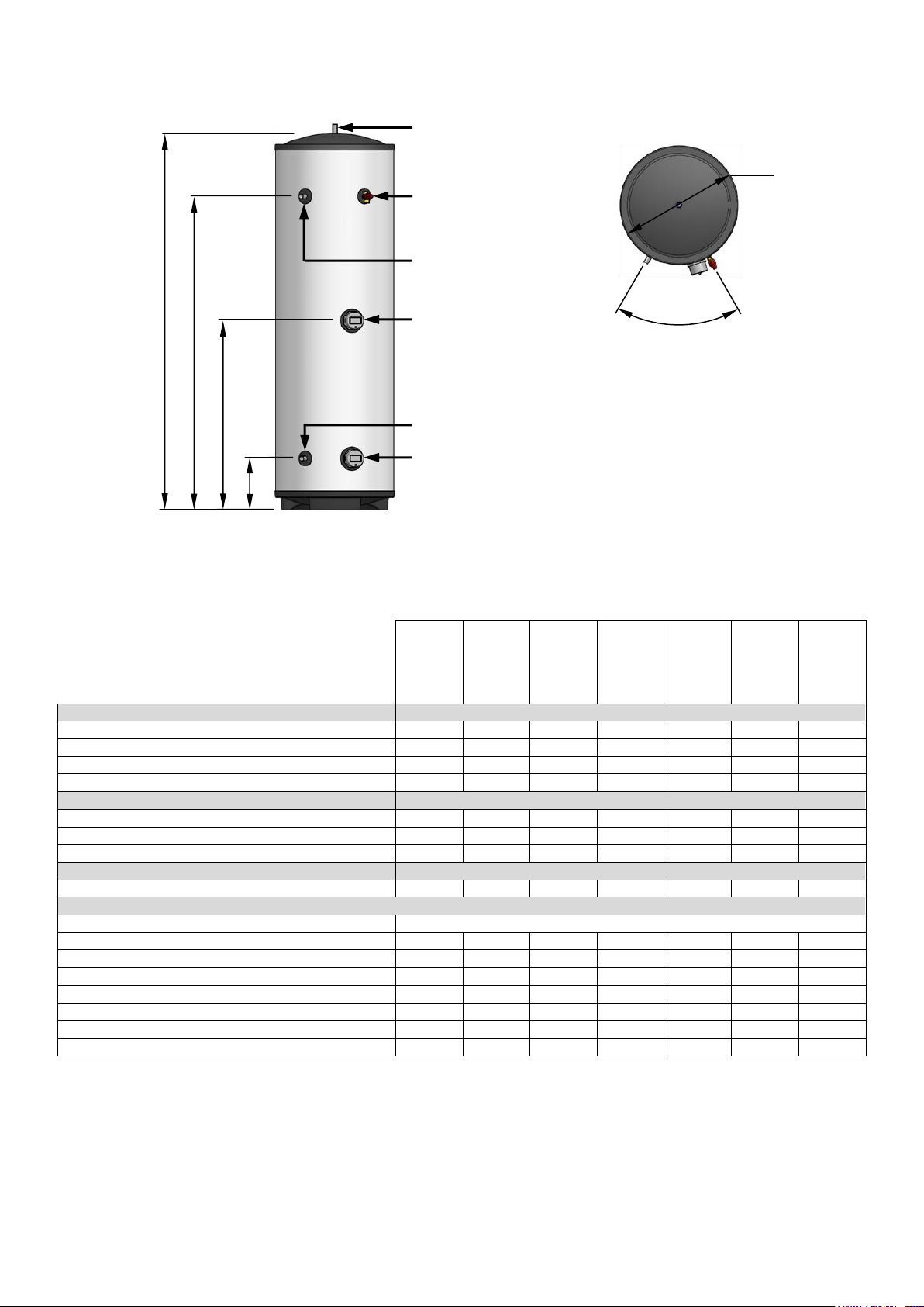
5.2 Direct Cylinders
DI90UV
DI120UV
DI150UV
DI180UV
DI210UV
DI250UV
DI300UV
DIMENSIONS
(A) Height (mm)
767
952
1142
1327
1517
1767
2077
(B) Secondary return connection / T&P (mm)
n/a
n/a
n/a
n/a
1223
1473
1783
(C) Upper immersion (mm)
n/a
482
577
670
765
890
1045
(D) Cold inlet connection / Lower immersion (mm)
243
243
243
243
243
243
243
OPERATING DATA
Cold water capacity (litres)
90
120
150
180
210
250
300
Weight when full (kg)
110
140
180
210
240
290
350
Standing heat loss (kWh/24h)
0.92
1.15
1.31
1.40
1.66
1.92
2.07
PERFORMANCE
Heat up time by lower immersion only (mins)
89
121
154
198
237
287
345
FICHE DATA
Supplier Name
Warmfllow
Supplier Model Identifier
DI90
DI120
DI150
DI180
DI210
DI250
DI300
Declared Load Profile
M M M L L
XL
XL
Energy Efficiency Class
D E D C D C C
Water Heating Energy Efficiency, ηwh (%)
34
30
36
38
37
39
39
Annual Electrical Consumption, AEC (kWh)
1541
1742
1452
2745
2799
4369
4351
Thermostat Setting (°C)
60
60
60
60
60
60
60
Sound Power Level (dB)
15
15
15
15
15
15
15
60°
Ø550
D
C
B
A
Hot Outlet (22mm)
Cold Inlet (22mm)
Temperature & Pressure
Relief Valve (15mm)
Upper Immersion Heater
Secondary Return (22mm)
Lower Immersion Heater
Figure 1: Direct cylinders components & dimensions
Table 2: Direct cylinder data
Page 5 of 23
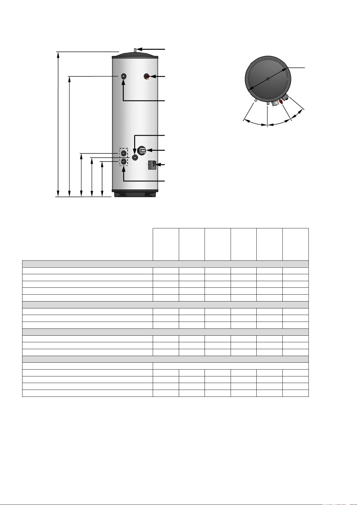
5.3 Indirect Cylinders
IN120UV
IN150UV
IN180UV
IN210UV
IN250UV
IN300UV
DIMENSIONS
(A) Height (mm)
952
1142
1327
1517
1767
2077
(B) Secondary return connection (mm)
n/a
n/a
n/a
1223
1473
1783
(C) Primary coil upper connection (mm)
462
462
532
532
532
532
(D) Cold inlet connection (mm)
412
412
482
482
482
482
(E) Primary coil lower connection (mm)
362
362
432
432
432
432
OPERATING DATA
Cold water capacity (litres)
120
150
180
210
250
300
Weight when full (kg)
140
180
210
250
290
350
Standing heat loss (kWh/24h)
1.15
1.31
1.40
1.66
1.92
2.07
COIL PERFORMANCE (EN12897)
Primary coil rating @ 15L/min (kW)
17.5
17.2
21.3
19.9
22.2
20.4
Primary coil pressure drop @ 15L/min (mbar)
54
54
67
67
67
67
Heat up time by primary coil (mins)
19.1
24.9
24.7
31.4
33.6
41.4
FICHE DATA
Supplier Name
Warmflow
Supplier Model Identifier
IN120
IN150
IN180
IN210
IN250
IN300
Energy Efficiency Class
A B B B C
C
Standing Loss (W)
36
55
58
60
84
86
Storage Volume (litres)
115
146
175
205
245
290
Ø550
E
C
B
Hot Outlet (22mm)
Cold Inlet (22mm)
Temperature & Pressure
Relief Valve (15mm)
Secondary Return (22mm)
Primary Coil Connections (22mm)
Primary Coil Thermostat
Immersion Heater
D
A
30°
30°
20°
Figure 2: Indirect cylinders components & dimensions
Table 3: Indirect cylinder data
Page 6 of 23
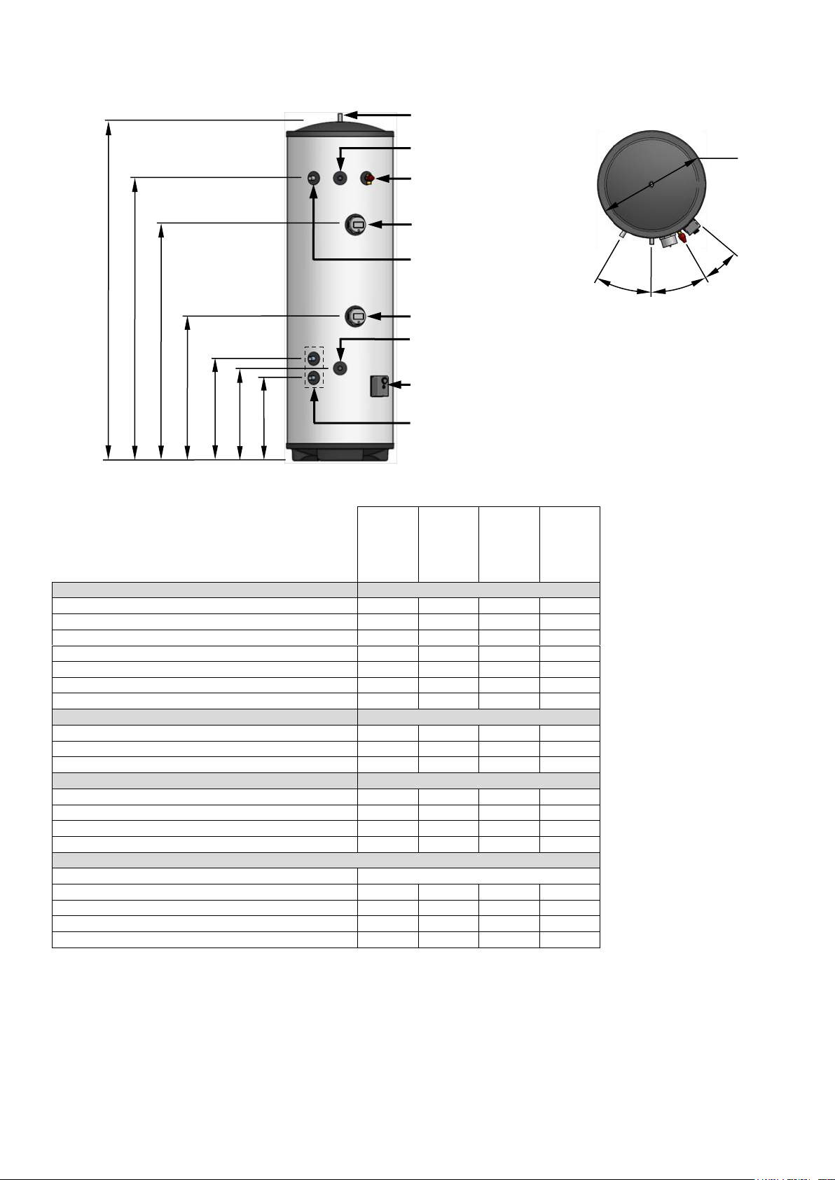
5.4 Eco Direct Cylinders
ED180UV
ED210UV
ED250UV
ED300UV
DIMENSIONS
(A) Height (mm)
1327
1517
1767
2077
(B) Secondary return connection (mm)
n/a
1223
1473
1783
(C) Upper immersion (mm)
891
1078
1230
1540
(D) Lower immersion (mm)
596
752
752
1062
(E) Renewable coil upper connection (mm)
532
532
532
532
(F) Cold inlet connection (mm)
482
482
482
482
(G) Renewable coil lower connection (mm)
432
432
432
432
OPERATING DATA
Cold water capacity (litres)
180
210
250
300
Weight when full (kg)
210
250
290
350
Standing heat loss (kWh/24h)
1.40
1.66
1.92
2.07
PERFORMANCE
Renewable coil rating @ 15L/min (kW)
21.4
20.2
21.8
19.3
Renewable coil pressure drop @ 15L/min (mbar)
67
67
67
67
Heat up time by lower immersion only (mins)
127
138
184
188
Dedicated renewable volume (litres)
65
90
110
145
FICHE DATA
Supplier Name
Warmflow
Supplier Model Identifier
ED180
ED210
ED250
ED300
Energy Efficiency Class
B
B C C
Standing Loss (W)
58
60
84
86
Storage Volume (litres)
175
205
245
290
30°
Ø550
G
E
D
Hot Outlet (22mm)
Cold Inlet (22mm)
Temperature & Pressure
Relief Valve (15mm)
Secondary Return (22mm)
Renewable Coil Connections (22mm)
Renewable Coil Thermostat
Lower Immersion Heater
F
30°
20°
Upper Immersion Heater
Sensor Pocket (1/2”)
C
B
A
Figure 3: Eco Direct cylinders components & dimensions
Table 4: Eco Direct cylinder data
Page 7 of 23
 Loading...