

WarmFlow 50/70, 70/90, 90/120, 120/150, 150/200 Installation & Servicing

50/70 – 70/90 – 90/120 – 120/150 – 150/200
BLUEBIRD BOILERHOUSE MODELS,
GOLDBIRD KITCHEN MODELS
& WHITEBIRD UTILITY ROOM MODELS
50/90
FRONT SERVICING BOILERS
GOLDBIRD KITCHEN MODEL
WHITEBIRD UTILITY ROOM MODEL
200/250
BLUEBIRD BOILERHOUSE MODEL
50/70 – 70/90
WHITEBIRD UTILITY ROOM SYSTEM BOILER
50/70 – 70/90 – 90/120 – 120/150 – 150/200
KABIN PAK EXTERNAL BOILERHOUSE MODULES
50/90
SLIMLINE KABIN PAK
EXTERNAL BOILERHOUSE MODULE
50/70 – 70/90
KABIN PAK BACK OUTLET
EXTERNAL BOILERHOUSE MODULES
300 – 400 – 500
CONVENTIONAL FLUED
INDUSTRIAL BLUEBIRD BOILERHOUSE MODELS
LEAVE THESE INSTRUCTIONS WITH THE END USER
INSTALLATION & SERVICING
MANUAL FOR

ISSUE 6.2
JAN ’04
COMMISSIONING
*THIS APPLIANCE MUST
BE COMMISSIONED
*Failure to commission the boiler will invalidate the warranty.
After commissioning ensure that the pre-paid
warranty registration card is completed
and returned.
SERVICING
To ensure continued reliable operation and fuel
economy it is recommended that the boiler is
serviced annually by an OFTEC registered
technician.
NI CUSTOMERS ONLY
Warmflow Engineering Service division (NI)
provides an excellent back-up service, operating
a team of OFTEC trained engineers who can
meet all the servicing, commissioning and
breakdown requirements for your appliance.
Telephone
0870 240 6532
Fax: 028 9262 2827
E-mail: service@warmflow .co.uk

Contents Page
1.0 User Instructions ............................................................................................................................................................ 2
1.1 Goldbird Models ................................................................................................................................................. 2
1.2 Bluebird, Kabin Pak and Whitebird Models ........................................................................................................ 2
1.3 Servicing ............................................................................................................................................................ 2
1.4 Components 50/70, 70/90, 90/120, 120/150, 150/200, 200/250 ........................................................................ 2
1.5 System Boiler ..................................................................................................................................................... 3
1.6 Components 50/90 Front Servicing Boiler
1.7 Components 300, 400 & 500 Industrial Boilers .................................................................................................. 4
1.8 Baffles ................................................................................................................................................................ 5
2.0 Introduction..................................................................................................................................................................... 6
2.1 General Requirements ....................................................................................................................................... 6
3.0 Dimensions ..................................................................................................................................................................... 7
3.1 Goldbird & Whitebird Models ............................................................................................................................. 7
3.2 Bluebird Models ................................................................................................................................................. 7
3.3 Industrial Bluebird Models .................................................................................................................................. 8
3.4 Kabin Pak ........................................................................................................................................................... 8
3.5 Kabin Pak Back Outlet ....................................................................................................................................... 9
3.6 Slimline Kabin Pak ............................................................................................................................................. 9
3.7 Flue Options ..................................................................................................................................................... 10
4.0 Installation..................................................................................................................................................................... 12
4.1 Service Access ................................................................................................................................................. 12
4.2 Hearth .............................................................................................................................................................. 12
4.3 Heating System ................................................................................................................................................ 12
4.4 Sealed System ................................................................................................................................................. 12
4.5 Air Vents........................................................................................................................................................... 13
4.6 Drain Cock ....................................................................................................................................................... 13
4.7 Expansion Vessels ........................................................................................................................................... 13
4.8 System Filling ................................................................................................................................................... 13
4.9 System Pressure .............................................................................................................................................. 13
5.0 Electricity Supply ......................................................................................................................................................... 14
5.1 Dual Thermostat............................................................................................................................................... 14
5.2 RDB Control Box .............................................................................................................................................. 14
5.3 Control Panel Wiring (Goldbirds) ..................................................................................................................... 15
5.4 R40 Control Box ............................................................................................................................................... 16
5.5 Installation of Optional Programmer................................................................................................................. 16
5.6 System Wiring Diagrams (Goldbirds) ............................................................................................................... 17
6.0 Technical Data............................................................................................................................................................... 19
6.1 Goldbird, Whitebird & Bluebird ......................................................................................................................... 19
6.2 Industrial Bluebirds........................................................................................................................................... 21
7.0 Air Supply...................................................................................................................................................................... 22
7.1 Open Flue Boilers ............................................................................................................................................ 22
7.2 Balanced Flue Boilers ...................................................................................................................................... 22
8.0 Flues ......................................................................................................................................................................... 23
8.1 Conventional Flues .......................................................................................................................................... 23
8.2 Low Level Flues ............................................................................................................................................... 23
8.3 Installation of Flues .......................................................................................................................................... 25
9.0 Installation of Boilers ................................................................................................................................................... 27
9.1 120/150 & 150/200 White Casings................................................................................................................... 27
9.2 Industrial Bluebird Casings .............................................................................................................................. 27
9.3 Industrial Firebrick ............................................................................................................................................ 27
9.4 Kabin Pak Installations ..................................................................................................................................... 29
9.5 Standard Kabin Paks ....................................................................................................................................... 30
9.6 Kabin Pak Vertical Flue Adaptor....................................................................................................................... 30
9.7 Slimline Kabin Pak ........................................................................................................................................... 31
9.8 Slimline Kabin Pak Vertical Flue Adaptor ......................................................................................................... 31
10.0 Oil Supply ...................................................................................................................................................................... 32
10.1 One Pipe System ............................................................................................................................................. 32
10.2 Two Pipe System ............................................................................................................................................. 33
10.3 Deaerator System ............................................................................................................................................ 33
10.4 One Pipe Lift .................................................................................................................................................... 34
11.0 Burners ......................................................................................................................................................................... 35
11.1 RDB Burner ...................................................................................................................................................... 35
11.2 G10 Burner....................................................................................................................................................... 35
11.3 G20S Burner .................................................................................................................................................... 36
11.4 Oil Supply ......................................................................................................................................................... 36
11.5 Air Damper Adjustment .................................................................................................................................... 37
11.6 Electrode Setting .............................................................................................................................................. 37
11.7 Burner Start-up Cycle....................................................................................................................................... 37
12.0 Servicing & Commissioning ........................................................................................................................................ 38
12.1 Commissioning................................................................................................................................................. 38
12.2 Servicing .......................................................................................................................................................... 38
13.0 User Instructions – Horstmann 626 Internal Programmer........................................................................................ 39
14.0 Fault Finding ................................................................................................................................................................. 44
15.0 Spares ......................................................................................................................................................................... 45
15.1 RDB Burners 1 & 2........................................................................................................................................... 45
15.2 RDB 3 & 4 Burners........................................................................................................................................... 46
15.3 R40 G10 Burner ............................................................................................................................................... 47
15.4 R40 G20S Burner............................................................................................................................................. 48
15.5 Boiler Parts List ................................................................................................................................................ 49
Page 1
1.0 User Instructions
1.1 Goldbird Models
Thermostat Control
The recommended minimum thermostat setting is 65°C. Below this ‘cold water corrosion’
is likely to occur which can reduce the life of the heat exchanger and is not covered by
the boiler warranty. The boiler thermostat is adjustable from 52°C to 88°C.
Mains Indicator
The green mains lamp will be lit when there is power to the control box.
H/L Reset
The yellow H/L reset lamp will be lit when the boiler has overheated and tripped the
high limit thermostat, which then needs to be manually reset. If the high limit thermostat
continues to trip, contact Warmflow or your service engineer/technician. The manual
reset thermostat has a cut out point of 110°C.
Lock-Out
The red lock out lamp will be lit when the burner has failed to fire and can be reset by
pressing the illuminated red reset button on the burner control box.
1.2 Bluebird, Kabin Pak and Whitebird Models
The recommended minimum thermostat setting is 65°C (thermostat setting 1). If the
high limit thermostat operates it may be reset by removing the reset cover and pressing
the reset button. If the burner goes to lockout it can be reset by pressing the illuminated
red reset button on the burner control box. Combustible material must not be placed
on top of the boilerhouse models or on top of the burner cover as the temperature of
certain exposed components can occasionally reach 70°C. The boiler thermostat is
adjustable from 60°C to 90°C and the manual reset limit thermostat has a set point of
110°C.
1.3 Servicing
It is recommended that the boiler is serviced annually by an OFTEC registered engineer.
WARNING: No adjustments to externally situated boilers should be made where wet
weather conditions prevail. In such conditions there may be a risk of ingress of water
into the appliance, which could lead to component failure or electrocution.
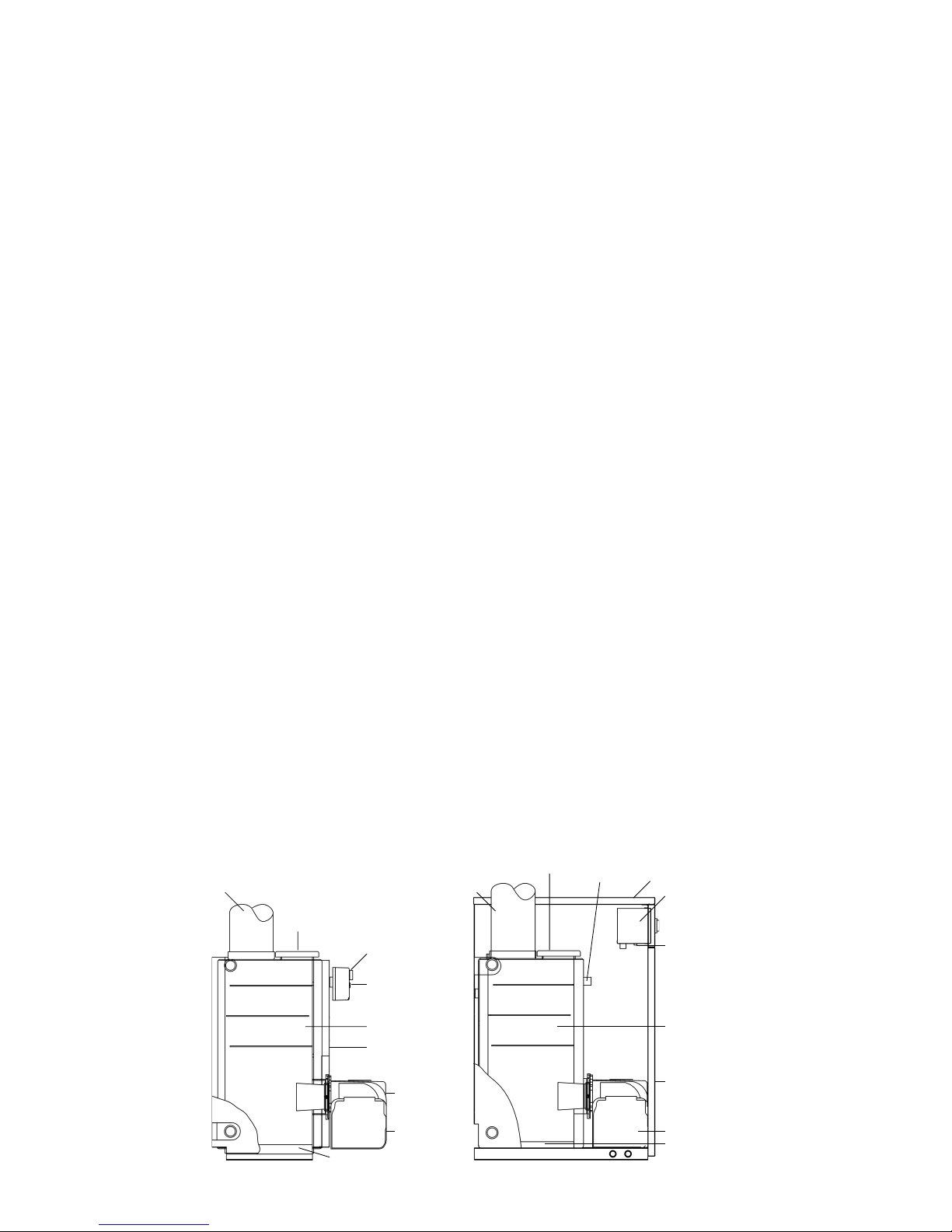
1.4 Components – 50/70, 70/90, 90/120, 120/150, 150/200, 200/250
LIMIT THERMOSTAT
RESET BUTTON COVER
BOILER
THERMOSTAT
CONTROL
TOP LID
FLUE
BURNER
LOCKOUT LAMP
& RESET BUTTON
BAFFLES
BOILER CASING
BURNER COVER
BASE INSULATION
TOP LID
FLUE
BURNER
LOCKOUT LAMP
& RESET BUTTON
BURNER COVER
BASE INSULATION
BAFFLES
LIMIT THERMOSTAT
MANUAL RESET
BUTTON COVER
BOILER
THERMOSTAT
CONTROL
THERMOSTAT
POCKET
BOILER
CASING
Bluebird Goldbird/Whitebird
Page 2
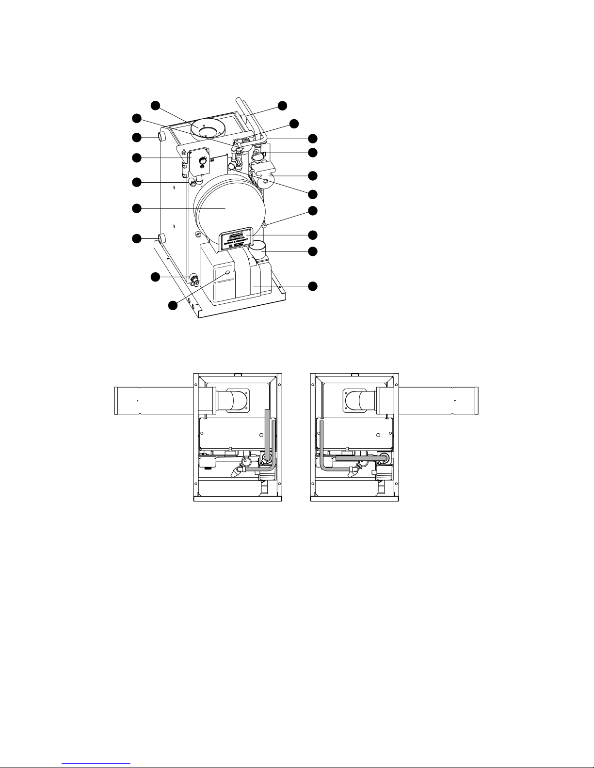
1 Flue
2 System Pressure Gauge
3 Spare BSP Connection (x2)
4 Boiler Limit Thermostat
5 Thermostat Pocket
6 12L Expansion Vessel
7 Heating Return (x2) 1” BSP
8 Drain Cock
9 Heating Flow
10 Automatic Air Vent
11 Pressure Relief Discharge
12 Isolation Gate Valve (x2)
13 Grundfoss Pump
14 Pressure Relief Valve
15 Filling Loop Connection
16 Data label
17 Optional Air Intake Spigot
18 RDB Burner
19 Burner Reset Button/Lock Out Lamp
1.5.2 Pipe Layout
1.5.3 Mains Water Supply
The mains water connection for the filling loop has been left free for the installer to fit
a 15mm copper pipe. The pipe can be routed over the top of the boiler, down one of
the side channels or through the cable entry grommets towards the front of the base
tray.
Note: Also our domestic appliances have been independently tested and accredited
as exceeding the minimum SEDBUK efficiency levels required for its type, in
compliance with the Building Regulations Approved Document L1 2001 for
England and Wales and the Building Standards (Scotland) Regulations 2001
Part J.
1.5 System Boiler
1.5.1 Components
18
17
16
15
14
13
12
11
10
9
8
7
6
4
3
2
1
19
5
Page 3
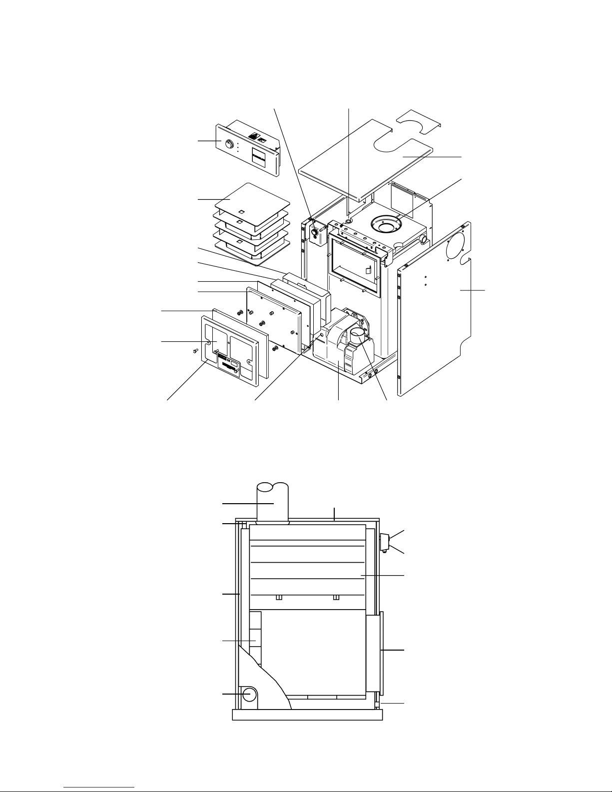
1.6 Components 50/90 Front Servicing Boiler
INSULATION
RETAINER
BOILER TEST POINT
EXTERNAL DOOR
INSULATION
BURNER RESET BUTTON/
LOCK OUT LAMP
RDB
BURNER
OPTIONAL AIR
INTAKE SPIGOT
SIDE
CASING
FLUE RING
TOP CASING
THERMOSTAT
POCKET
WHITEBIRD
THERMOSTAT
GOLDBIRD
CONTROL PANEL
BAFFLES
INSULATION SHIELD
DOOR INSULATION
DOOR GASKET
SERVICE DOOR
BOILER CONTROL
THERMOSTAT
LIMIT THERMOST AT
RESET BUTTON COVER
SERVICING DOOR
1" BSP DRAIN VALVE
CONNECTION
BAFFLES
4 No 3" BSP CONNECTIONS
FIREBRICK REAR
AND BOTTOM
BOILER CASING
2 No 1/2" BSP CONNECTIONS
FLUE TOP LID
1.7 Components – 300, 400 and 500 BB Industrial Boilers (x 1000 Btu/hr)
Page 4
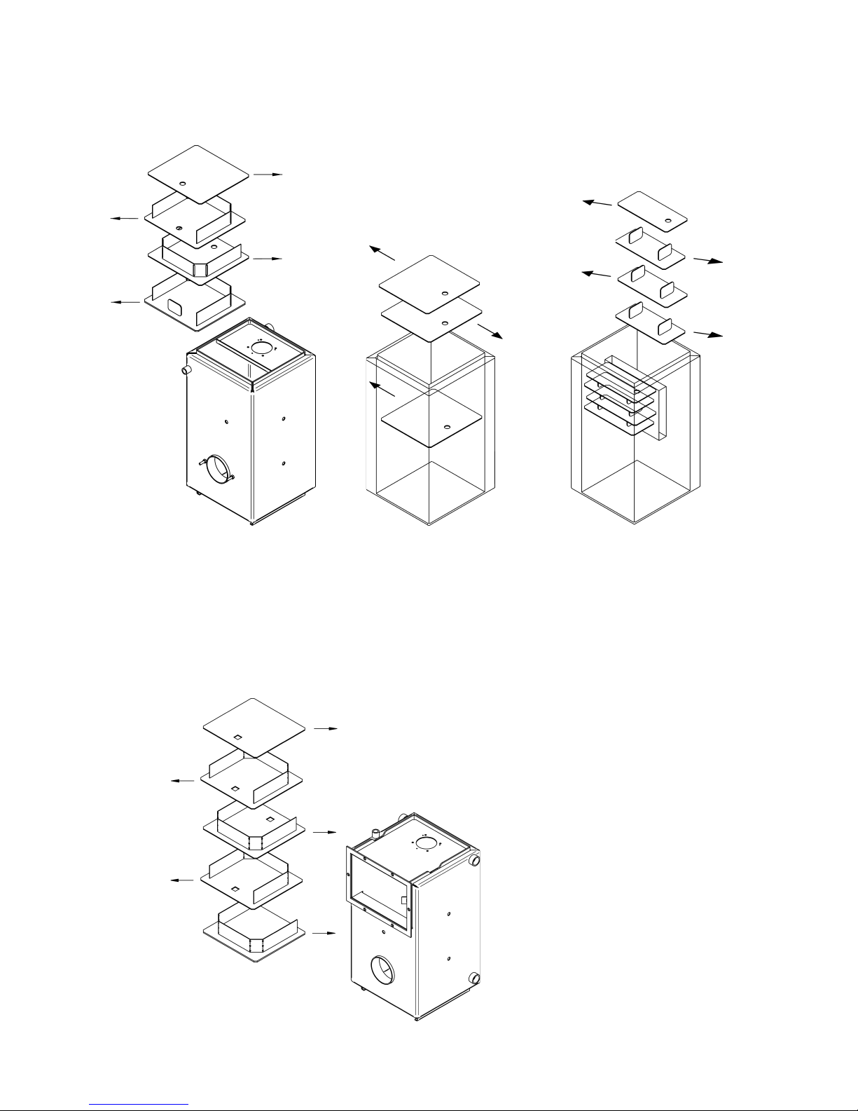
1.8 Baffles
1.8.1 Top Servicing Boilers
50/70
(3 in number)
70/90 & 120/150 (8 in number)
90/120, 150/200, 300, 400 & 500
have a similar arrangement
(12, 12, 12, 16 and 16
baffles respectively)
FRONT FRONT
50/90
(4 in number)
heavy baffle to the bottom
Note: Before firing make sure
the baffles have not been
dislodged in transit and are
correctly positioned. T o achieve
maximum efficiency push the
baffles in the direction of the
arrows as shown.
1.8.2 Components 50/90 Front Servicing Boiler
50/90
(5 in number)
heavy baffle to the bottom
Page 5

2.0 Introduction
The boilers are fired by a pressure jet oil burner which is covered by the manufacturer’s
parts and labour warranty valid for one year (from boiler date stamp). Optional extended
guarantees covering parts and labour are also available (although not applicable to
the Republic of Ireland).
Warmflow oil fired boilers are designed to burn 28 second redwood No 1 (Kerosene
Class C2) fuel or with some adjustment 35 second redwood No 1 (Gas Oil Class D). In
order to comply with current building regulations only kerosene must be burned when
used with low level flue or low level balanced flue. The 400 and 500 Bluebirds are only
suitable for use with 35 second redwood No 1 (Gas Oil Class D).
The boiler shells are fabricated from the best quality mild steel plate electrically welded
and pressure tested to 4.5 bar (65 PSI) making them suitable for either open or
pressurised systems (max working pressure 1.5 bar). Note that all industrial boilers
are tested to 6 bar (90 PSI). They incorporate two flow and return connections on each
side of the boiler for connection to the central heating and domestic hot water systems.
Each shell is covered by the manufacturer’s warranty of 5 years (effective from date
stamped on warranty label) but does not include burner, labour, handling or shipping.
The manufacturers guarantees are void if the appliance is not installed and
commissioned and serviced in accordance with the recommendations made herein.
2.1 General Requirements
The installation of the boiler must be in accordance with the following regulations.
BS5410 : PART 1 : 1997 Code of Practice for oil firing.
BS5410 : PART 2 : 1977
BS5449 : PART 1 : 1977 Forced Circulation Hot Water Systems.
BS7593 : 1992 Treatment of water in domestic hot water central heating systems.
Current Building Regulations: Part J England and Wales
Part F Section III Scotland
Part L Northern Ireland
Current IEE Wiring Regulations:
The heating system should be installed by a competent installer in accordance with
the recommendations laid down by HVCA and a sound engineering practice.
In order to comply with GB building regulations OFTEC forms CD10 for
installations and CD11 for commissioning should be left with the customer.
Page 6

H
A
B
J
F
D
E
C
= =
G
K
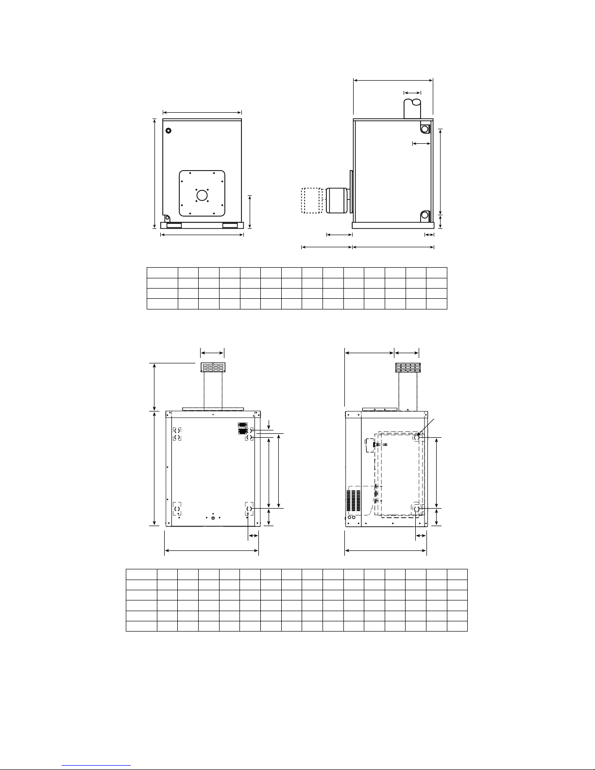
3.0 Dimensions
3.1 Goldbird Kitchen, Whitebird and Whitebird System Utility Room Models (including
front servicing boilers)
J
127
127
127
127
127
OUTPUT (kW)
14.6-20.5
20.5-26.4
26.4-35.2
35.2-44.0
44.0-58.6
A
865
865
865
1168
1168
B
413
413
595
495
495
C
599
599
599
785
785
D
90
90
90
102
102
E
59
59
59
72
72
F
554
554
541
809
809
G
664
664
664
956
956
H
128
128
128
128
128
MODEL
50-70
70-90
90-120
120-150
150-200
K
4x1”
4x1”
4x1
1
/2”
4x1
1
/2”
4x1
1
/2”
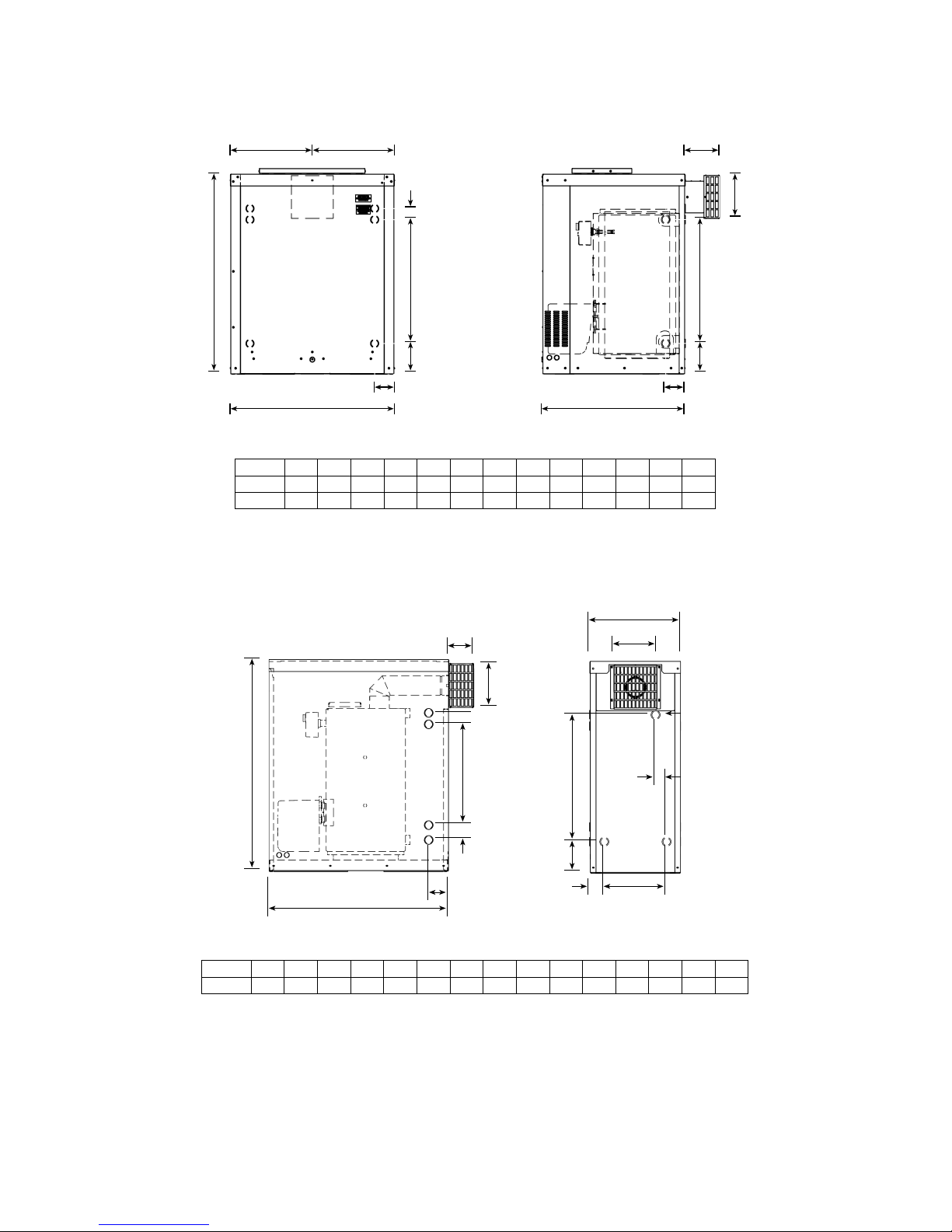
3.2 Bluebird Boilerhouse Models
B E
K
= = J
H
C
A
F G
D
L
J
127
127
127
127
127
152
A
688
688
688
965
965
965
B
405
405
585
490
490
490
C
387
387
392
530
530
530
D
88
88
88
102
102
102
E
62
62
67
72
72
72
F
554
554
541
809
809
809
G
662
662
662
956
956
956
H
130
130
138
119
119
139
MODEL
50-70
70-90
90-120
120-150
150-200
200-250
OUTPUT (kW)
14.6-20.5
20.5-26.4
26.4-35.2
35.2-44.0
44.0-58.6
58.6-73.3
K
188
188
188
188
246
246
L
4x1”
4x1”
4x1
1
/2”
4x1
1
/2”
4x1
1
/2”
4x1
1
/2”
Page 7
B
M
E
L
N Q
P
A
D
C
K
FG
H
J
R
3.3 Industrial Bluebird Models
3.4 Kabin Pak
The Kabin Pak comes factory fitted with a Warmflow Bluebird Boiler and insulated low
level flue kit complete with a terminal guard.
An adaptor is available to allow the low level flue to be extended using standard twin
wall round flue. Only the outer flue and flue end cap need be removed.
D
G
J
A
E
F
N
B
K
L
MH
C
MODEL
50-70
70-90
90-120
120-150
150-200
J
554
554
541
809
809
A
892
892
892
1089
1089
B
732
732
942
902
902
C
636
636
636
836
836
D
373
373
373
373
373
E
188
188
188
188
188
F
191
191
191
191
191
G
390
390
390
602
602
H
137
137
137
151
151
K
84
84
84
96
96
L
86
86
86
86
86
M
137
137
137
191
191
N
554
554
554
—
—
P
50
50
50
—
—
Q
—
—
—
729
729
MODEL
300
400
500
J
412
446
461
A
814
934
1062
B
824
934
1072
C
864
974
1085
D
864
974
1085
E
432
407
464
F
1313
1313
1570
G
263
263
297
H
272
306
321
K
166
166
170
L
1032
1032
1466
M
111
111
102
N
203
203
203
Page 8
P
K
A
F
D
E
G
I
H
B
L
C
J
M
N
Q
J
B
H
C
== D
K
L
M
A
G
F
E x N
3.5 Kabin Pak Back Outlet
MODEL
50-70
70-90
J
85
85
A
892
892
B
732
732
C
636
636
D
156
156
E
191
191
F
554
554
G
138
138
H
85
85
K
137
137
L
554
554
M
50
50
N
188
188
3.6 Slimline Kabin Pak
When installing a Slimline Kabin Pak against a wall allow 600mm to the front and rear
of the appliance for servicing.
MODEL
50-90
I
190
A
784B925C398D109E86F65G440H50
J
272K61L188M134N554P48
Page 9
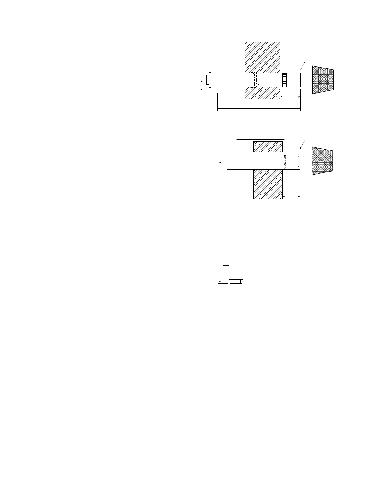
3.7 Flue Options
3.7.1 ‘Easy Fit’ Low Level Balanced Flue
The horizontal dimension can be
increased up to an additional
1200mm using a combination of long
extension pieces (600mm) and short
extension pieces (300mm).
102
712 MAX
225 MAX
175 MIN
490 MIN
Ø125
3.7.2 ‘Easy Fit’ High Level Balanced Flue
The HLBF is available in 4 fixed
horizontal lengths which are:
Option 1 – 455mm
Option 2 – 655mm
Option 3 – 585mm
Option 4 – 785mm
225 MAX
175 MIN
1128
SEE OPTIONS
160x160
Page 10
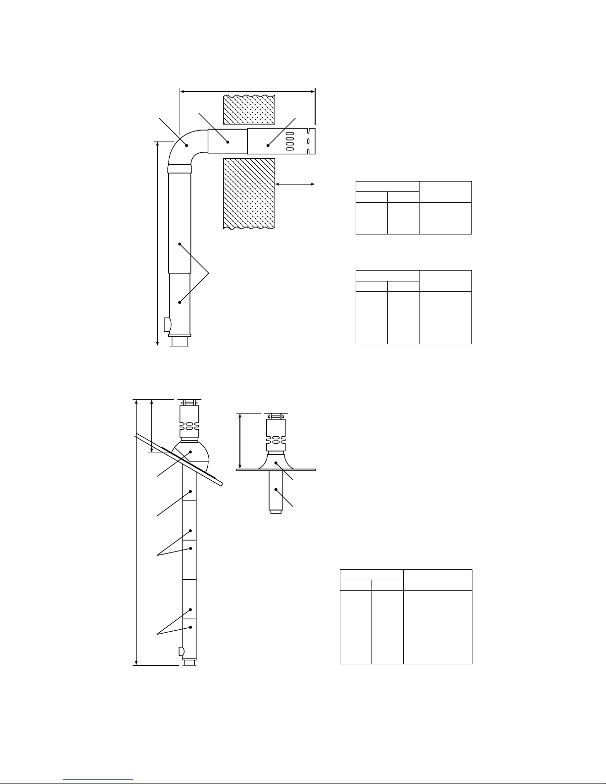
3.7.4 Easy Fit Vertical Balanced Flue (VBF)
EXTENSION KITS
AS REQUIRED
(PACKS C OR D)
PACK E OR F PACK E OR F
A
175 MIN
225 MAX
900 MIN
1400 MAX
PACK A
PACK H
PITCHED ROOF
FLASHING
(22" – 45"
ADJUSTABLE)
PACK B
VBF TERMINAL
SECTION
EXTENSION KITS
(PACK C OR D) AS
REQUIRED
MAX 2 NO PACK D
PACK A
675mm
MIN
675mm
MIN
PACK G
FLAT ROOF
FLASHING
PACK B
VBF TERMINAL
SECTION
MIN
435
560
735
MAX
610
860
910
A + E
A + F
A + C + E
FLUE PACKS
DIM A
ALL MODELS
MIN
860
1035
1160
1385
1510
MAX
1160
1210
1510
1560
1860
A + C + F
A + C + C + E
A + C + C + F
A + D + E
A + D + F
FLUE PACKS
DIM A
50/70, 70/90 & 90/120 MODELS ONLY
MIN
1340
1640
1940
2290
2590
2890
3240
MAX
1840
2140
2440
2740
3040
3340
3740
A + B
A + B + C
A + B + C + C
A + B + D
A + B + D + C
A + B + D + C + C
A + B + D + D
FLUE PACKS
FLUE HEIGHT
ALL MODELS
Note: When using a VBF or HLBF-R on a 120/150 or 150/200 model ensure that the boiler is
fitted with a RDB3 burner.
3.7.3 Easy Fit Telescopic High Level Balanced Flue (HLBF-R)
Page 11

4.0 Installation
The boiler installation must be in compliance with BS 5410 and the Building Regulations.
Failure to install and commission in accordance with the instructions contained
within this booklet will invalidate the warranty.
4.1 Service Access
24” (600mm) clearance should be provided above and in front of the boiler (and the
rear for Slimline Kabin Paks) to allow for routine servicing. When top servicing boilers
are placed under a worktop ensure that the worktop is easily removed.
4.2 Hearth
The boiler hearth temperature is between 50°C and 85°C to comply with the Building
Regulations. The boiler should be stood on a rigid, non-porous, non-combustible base,
which is not softened by warmth. For the heavier industrial boilers it would be advisable
to have a level concrete base raised 50mm above floor level.
4.3 Heating System
The heating system should be installed to HVCA current codes of practice and the
recommendations made in the relevant British Standards.
The use of inappropriate pipe sizes and incorrect plumbing leading to system and
boiler noise is not covered under the boiler warranty.
It is recommended that the flow and return pipes are connected on opposite sides of
the boiler.
It is recommended that new and existing systems are commissioned in accordance
with BS7593 : 1992 ‘Treatment of water in central heating systems’. It is recommended
that a non-corrosive commissioning cleanser is used when flushing the system.
We would also recommend that the system is further treated with a corrosion inhibitor .
These products should be used strictly in accordance with the manufacturers
instructions.
In areas of hard water a suitable water softener would also be recommended.
4.4 Sealed Systems
All Warmflow boilers are suitable for use on a sealed heating system. It is recommended
that a CE approved pressure relief valve (PRV) set at 3 bar is fitted to the system. The
industrial bluebirds can be fitted with a 4 bar PRV. On the system boiler a 3 bar PRV
has been factory fitted.
Page 12

4.5 Air Vents
On the system boiler an automatic air vent complete with its own check valve is fitted
to the top of the boiler heat exchanger. It is recommended that an air vent is fitted at
the highest point in the system. However where the pipework comes off the boiler and
drops down an automatic airvent should be fitted to the top of the boiler.
4.6 Drain Cock
Drain cock(s) should be fitted to the lowest points in the system to enable the system
to be fully drained. On the system boiler a drain cock has been fitted to the system
boiler heat exchanger.
4.7 Expansion Vessels
Refer to BS 7074: part 1 or BS 5449 for details of the pressure vessel sizing. The
values given in the table are for a total system values which includes the primary water
capacity . On the system boiler a 12 litre expansion vessel charged to 0.5 bar is supplied.
This can accommodate a maximum system volume of approximately 150 litres. If this
volume is exceeded an additional vessel will be required.
0.5 2.1 4.2 6.3 8.3 10.5 12.5 14.6 16.7 18.7 20.8 22.9 25.0
1.0 2.7 5.4 8.2 10.9 13.6 16.3 19.1 21.8 24.5 27.2 30.0 32.7
1.5 3.9 7.8 11.7 15.6 19.5 23.4 27.3 31.2 35.1 39.0 42.9 46.8
25 50 75 100 125 150 175 200 225 250 275 300
INITIAL CHARGE
TOTAL
SYSTEM
VOLUME
VESSEL VOLUMES
4.8 System Filling
Water loss from a sealed system, as indicated by a reduction in pressure on the pressure
gauge, may be made up through a filling loop, however the cause of the water loss
should be fully investigated and corrected.
After filling, vent all air from the system. Ensure the caps on the automatic air vents are
loose, bleed the circulating pump and disconnect the temporary filling loop.
As standard, a filling point complete with a filling loop has been included within the
system boiler. A system pressure, when cold, of 1 bar is recommended.
4.9 System Pressure
The pressure relief discharge shall be positioned away from any electrical components.
No other valves should be positioned between the relief valve and the discharge, and
the discharge pipes should not be used for any other purposes. The discharge pipe
must be plumbed to an external drain in a position where the discharge can be seen
but cannot cause any injury or damage.
Where there is a catastrophic loss of water from the system the boiler thermostats
may fail to operate which would result in serious damage to the appliance. To prevent
this it is recommended that a low pressure cut out switch set at 0.2 bar is fitted to the
system and wired in series with the boiler thermostats.
Page 13
TO BURNER
FROM POWER SUPPLY (SWITCHED LIVE)
5.0 Electricity Supply
220 – 240V. 1PH, 50 Hz
The boiler/burner and other external electrical equipment should be wired with heat
resistant cable via a fused double pole isolating switch which should be fitted with a
5 amp fuse.
The appliance must be effectively earthed and all external wiring should comply with
current IEE Regulations.
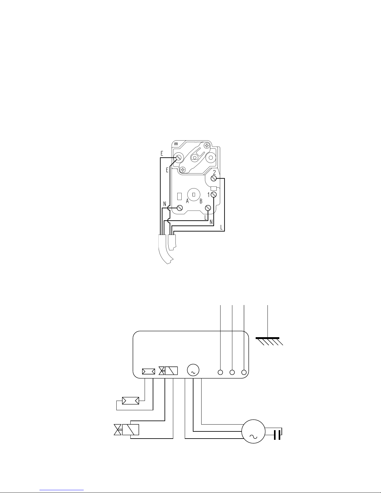
5.1 Dual Immersion Thermostat (Bluebird and Whitebird Boilers)
CONTROL BOX
535SE/LD
M
M
Oil Valve
Photoresistance
Black
White
Blue
Motor
Capacitor
Remote
Lock Out
(Goldbirds only)
Live
Neutral
Earth
Fan
Housing
Note: A remote lock out lamp is only factory fitted wired on Goldbird models.
Warning: Do not fit any other wires or loop wires to this stat as this will bypass the
thermostats.
5.2 RDB Burner Control Box
Page 14
 Loading...