

WarmFlow 50/70 Installation & Servicing Manual
INSTALLATION & SERVICING MANUAL FOR
50/70
WALL MOUNTED BOILER
(INTERNAL)
&
50/70
WALL MOUNTED BOILER
(EXTERNAL)
LEAVE THESE INSTRUCTIONS WITH THE END USER
NATIONAL
ACCREDITATION
OF CERTIFICATION
BODIES
BSI
R
E
G
I
S
T
E
R
E
D
F
I
R
M
CERT. No. FM 29884
BS 5750 PART 2
ISO 9002

Page 2
Commissioning
This appliance must be commissioned. Failure to commission the boiler will
invalidate the warranty. After commissioning ensure that the attached
guarantee registration card is completed and returned.
Servicing
To ensure continued reliable operation and fuel economy it is recommended
that the boiler is serviced annually by a Warmflow or an OFTEC registered
technician.
NI Customers Only
Warmflow Engineering Service division (NI) provides an excellent back-up
service, operating a team of OFTEC trained engineers who can meet all the
servicing, commissioning and breakdown requirements for your appliance.
Telephone: 0870 240 6532
Fax: 028 9262 2827
Email: service@warmflow.co.uk
Web: www.warmflowboilers.co.uk
For Parts, Service Technical & Warranty Contact
Great Britain & N Ireland, Tel: 0870 240 6532
Republic of Ireland, Tel: +44 28 9262 1515
ISSUE 2
AUG ’05
This manual is accurate at the date of printing (E&OE) but will be superseded and should be disregarded
if specifications and/or appearances are changed in the interests of continued product improvement.
Code 2614
Lisburn
Lissue Industrial Estate, Moira Road,
Lisburn, Co Antrim, N Ireland, BT28 2RF
Tel: (028) 9262 1515
Fax: (028) 9262 0869
Email: sales@warmflow.co.uk
technical@warmflow.co.uk
service@warmflow.co.uk
Manchester
144 Bradford Road,
Manchester, M40 7AS
Tel: (0161) 205 4202
Fax: (0161) 205 4818
Email: sales@warmflowgb.co.uk
technical@warmflowgb.co.uk
service@warmflowgb.co.uk

Page 3
Contents Page
1.0 User Instructions
1.1 Thermostat Control ......................................................................................................................................... 2
1.2 Mains Indicator ............................................................................................................................................... 2
1.3 Lock Out ......................................................................................................................................................... 2
1.4 Servicing ......................................................................................................................................................... 2
1.5 User Instructions – Wall Mounted (Internal) .................................................................................................... 3
1.6 User Instructions – Wall Mounted (External) ................................................................................................... 4
1.7.1 Components – Wall Mounted Boiler (Internal) ................................................................................................ 5
1.7.2 Components – Wall Mounted Boiler (External) ............................................................................................... 6
2.0 Introduction
2.1 General Requirements .................................................................................................................................... 7
3.0 Dimensions
3.1 50/70 Wall Mounted Boiler (Internal) ............................................................................................................... 8
3.2 50/70 Wall Mounted Boiler (External) ............................................................................................................. 8
3.3 Easy Fit Low Level Conventional Flue (LLF-R) ............................................................................................... 9
4.0 Installation Requirements
4.1.1 Service Access for WM Boiler (Internal) ......................................................................................................... 9
4.1.2 Servicing ......................................................................................................................................................... 9
4.1.3 Heating System ............................................................................................................................................... 9
4.2 Sealed Systems ............................................................................................................................................ 10
4.2.1 Air Vents ........................................................................................................................................................ 10
4.2.2 Drain Cock .................................................................................................................................................... 10
4.2.3 Expansion Vessels ........................................................................................................................................ 10
4.2.4 System Filling ................................................................................................................................................ 10
4.2.5 Pressure Relief Valve ..................................................................................................................................... 10
4.2.6 Low Pressure Switch .................................................................................................................................... 10
5.0 Boiler Installation
5.1 Heat Exchanger Installation .......................................................................................................................... 11
5.2 Internal Boiler Casing Installation ................................................................................................................. 12
5.3 External Boiler Casing Installation ................................................................................................................ 13
5.4 Baffles ........................................................................................................................................................... 14
6.0 Electricity Supply
6.1 RDB Burner Control Box ............................................................................................................................... 14
6.2.1 Control Panel Wiring (Wall Mounted Boilers – Internal) ................................................................................ 15
6.2.2 Control Panel Wiring (Wall Mounted Boilers – External) ............................................................................... 16
7.0 Technical Data ............................................................................................................................................................. 17
8.0 Air Supply
8.1 Open Flue Boilers ......................................................................................................................................... 18
8.2 Balanced Flue/Room Sealed Boilers ............................................................................................................ 18
9.0 Flues
9.1 Conventional Flues ....................................................................................................................................... 19
9.2 Low Level Conventional Flue Positions ........................................................................................................ 19
9.3 Low Level Conventional Flue Installation ...................................................................................................... 21
9.4 Installation of Air Intake Duct ........................................................................................................................ 22
9.5 Wall Mounted Boiler (External) Flue Adaptor Installation .............................................................................. 23
9.5.1 Option A ........................................................................................................................................................ 23
9.5.2 Option B ........................................................................................................................................................ 23
10.0 Oil Supply
10.1 One Pipe System .......................................................................................................................................... 24
10.2 Two Pipe System .......................................................................................................................................... 25
10.3 De-aerator System ........................................................................................................................................ 25
10.4 One Pipe Lift System .................................................................................................................................... 26
11.0 RDB Burner
11.1 Components ................................................................................................................................................. 27
11.2 Oil Pump ....................................................................................................................................................... 27
11.3 Air Damper Adjustment ................................................................................................................................. 28
11.4 Electrode Setting .......................................................................................................................................... 28
11.5 Start-Up Cycle .............................................................................................................................................. 28
12.0 Servicing & Commissioning
12.1 Commissioning ............................................................................................................................................. 29
12.2 Servicing ....................................................................................................................................................... 29
12.2.1 General Requirements .................................................................................................................................. 29
12.2.2 External Wall Mounted Boilers ...................................................................................................................... 29
13.0 Fault Finding ................................................................................................................................................................ 30
14.0 Spares
14.1 Burner Spares ............................................................................................................................................... 31
14.2 Short Parts List (Boiler) ................................................................................................................................. 32

Page 4
1.0
User Instructions
All our domestic appliances have been independently tested and accredited as exceeding
the minimum SEDBUK efficiency levels required for its type, in compliance with the
Building Regulations Approved Document L1 2001 for England and Wales and the
Building Standards (Scotland) Regulations 2001 Part J.
1.1 Thermostat Control
The recommended minimum thermostat is 65°C. Below this ‘cold water corrosion’ is
likely to occur which can reduce the life of the heat exchanger and is not covered by
the boiler warranty. The boiler thermostat is adjustable from 54°C to 84°C.
1.2 Mains Indicator
The green mains lamp will be lit when there is power to the control and limit thermostats.
The yellow high limit reset lamp will be lit when the boiler has overheated and tripped
the high limit thermostat, which then needs to be manually reset. If the high limit
thermostat continues to trip, contact Warmflow or your service engineer/technician.
The manual reset thermostat has a cut out point of 110°C.
1.3 Lock Out
The red lock out lamp will be lit when the burner has failed to fire and can be reset
by pressing the illuminated red reset button on the burner control box.
Note: On the external wall mounted boiler the thermostat control indication lamps and high
limit reset button are located behind the lockable plastic cover.
1.4 Servicing
It is recommended that the boiler is serviced annually by an OFTEC registered engineer.
Page 5
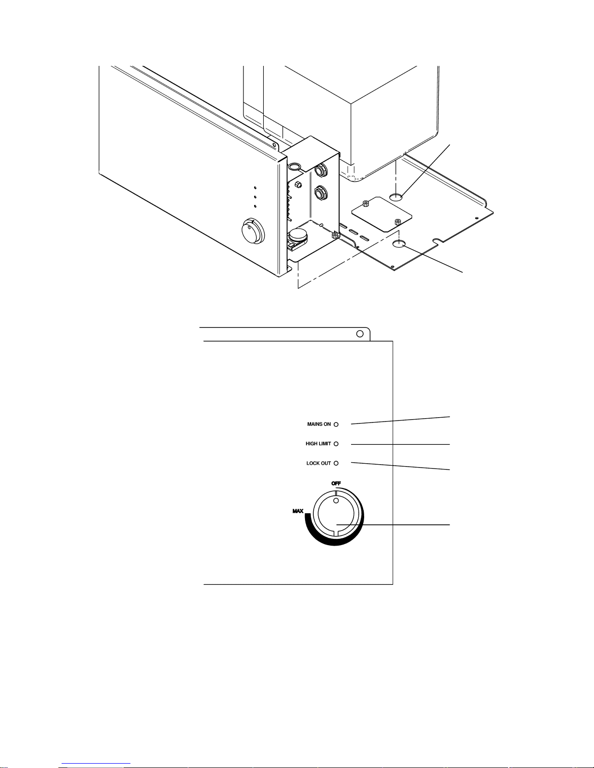
1.5 User Instructions – Wall Mounted (Internal)
BURNER
LOCK-OUT
RESET
LIMIT STAT RESET
GREEN
AMBER
RED
CONTROL
THERMOSTAT
(54°C – 84°C)
BURNER
LOCK-OUT
RESET (FROM
UNDERNEATH)
HIGH LIMIT
STAT RESET
(FROM
UNDERNEATH)
➔
➔
Page 6
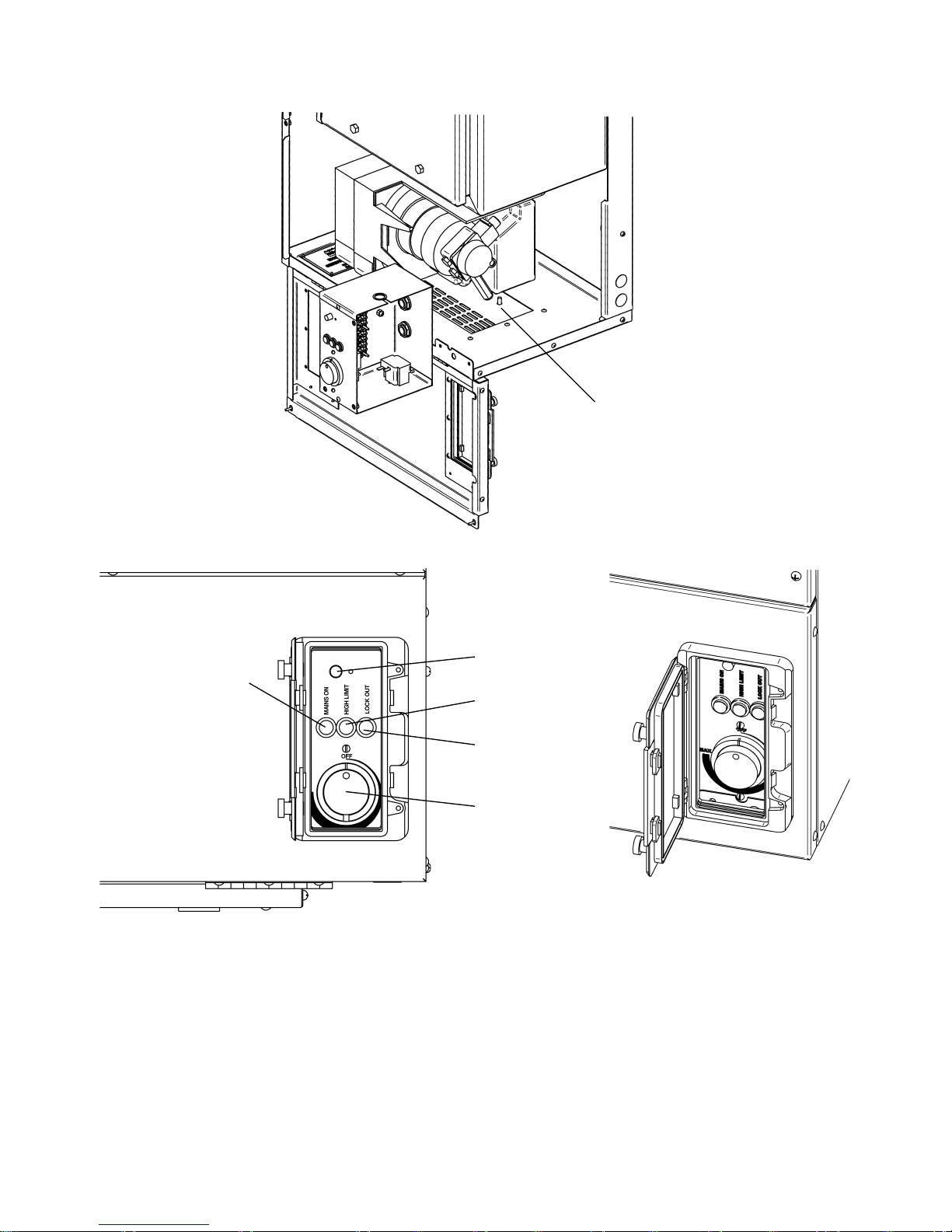
1.6 User Instructions – Wall Mounted (External)
HIGH LIMIT RESET
AMBER
RED
CONTROL
THERMOSTAT
(54°C – 84°C)
GREEN
BURNER LOCKOUT RESET
(FROM UNDERNEATH)
BURNER
LOCKOUT RESET
(FROM UNDERNEATH)
Page 7
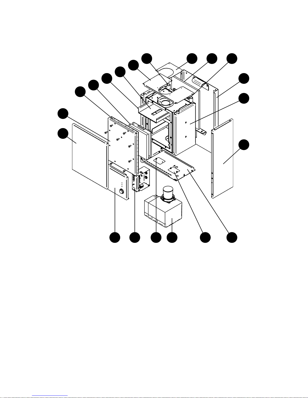
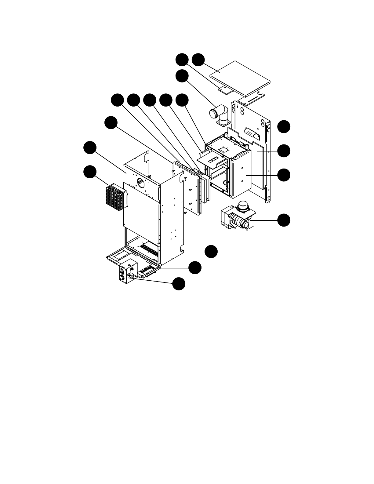
1.7 Components
1.7.1 Components – Wall Mounted Boiler (Internal)
1. Front Casing
2. Combustion Chamber Door
3. Door Gasket
4. Door Insulation
5. Top Baffle Support
6. Top Baffle
7. Top Casing & Insulation
8.
3
/4” BSP Flow Connection
9. Flue Closing Plate
10. Mounting Plate Insulation
1
2
3
4
5
6
7
8 9 10 11
12
13
14
1516171920 18
11.
3
/4” BSP Return Connection
12. Mounting Plate
13. Heat Exchanger
14. Side Casing
15. Bottom Casing
16. Oil Pump Access Plate
17. Burner
18. Air Damper Access Plate
19. Control Panel
20. Control Panel Casing
Page 8
1
2
3
4 5 6 7 8
9
10 11
12
13
14
15
16
17
18
1.7.2 Components – Wall Mounted Boiler (External)
1. Flue Terminal Guard
2. Main Casing Assembly
3. Combustion Chamber Door
4. Door Gasket
5. Door Insulation
6. Insulation Heat Shield
7. Top Baffle Support
8. Top Baffle
9. Flue Elbow
10. Top Insulation
11. Top Casing
12. Mounting Plate
13. Mounting Plate Insulation
14. Heat Exchanger
15. Burner
16. Bottom Baffles
17. Controls Inspection Flap
18. Control Panel

Page 9
2.0 Introduction
The boilers are fired by a pressure jet oil burner which is covered by the manufacturer’s
parts and labour warranty valid for one year (from boiler date stamp). Optional
extended guarantees covering parts and labour are also available (although not
applicable to the Republic of Ireland).
The Warmflow wall mounted oil fired boilers are designed to burn 28 second redwood
No 1 (Kerosene Class C2) fuel.
The boiler shells are fabricated from the best quality mild steel plate electrically
welded and pressure tested to 4.5 bar (65 PSIG) making them suitable for either open
or pressurised systems (max working pressure 1.5 bar). They incorporate one flow
and return connection on the top of the boiler for combined connection to the
central heating and domestic hot water systems. Each shell is covered by the
manufacturer’s warranty of 5 years (effective from date stamped on warranty label)
but does not include burner, labour, handling or shipping.
The manufacturers guarantees are void if the appliance is not installed and commissioned
and serviced in accordance with the recommendations made herein.
2.1 General Requirements
The installation of the boiler must be in accordance with the following regulations.
BS5410 : PART 1 : 1997 Code of Practice for oil firing.
BS5410 : PART 2 : 1997
BS5449 : PART 1 : 1977 Forced Circulation Hot Water Systems.
BS7593 : 1992 Treatment of water in domestic hot water central heating systems.
Current Building Regulations: Part J England and Wales
Part F Section III Scotland
Part L Northern Ireland
Current IEE Wiring Regulations:
The heating system should be installed by a competent installer in accordance with
the recommendations laid down by HVCA and a sound engineering practice.
In order to comply with GB building regulations OFTEC Form CD10 for installations
and CD11 for commissioning should be left with the customer.
Page 10
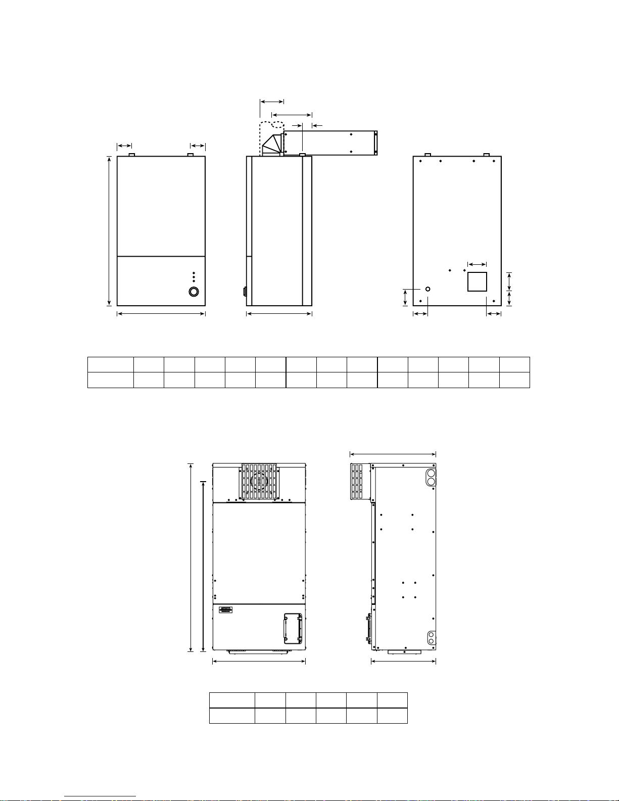
3.0 Dimensions
3.1 50/70 Wall Mounted Boiler (Internal)
F
D D
A B
E
C
H J
M
G
K
L
FRONT VIEW SIDE VIEW REAR VIEW
N
MODEL
50-70 WM
J
77
A
450B330C762D79E100F207G86
H
73
K
77
L
90
M
90
N
22
3.2 50/70 Wall Mounted Boiler (External)
MODEL
50-70 WMEA502B349C1023D465E926
BA
D
EC
Page 11
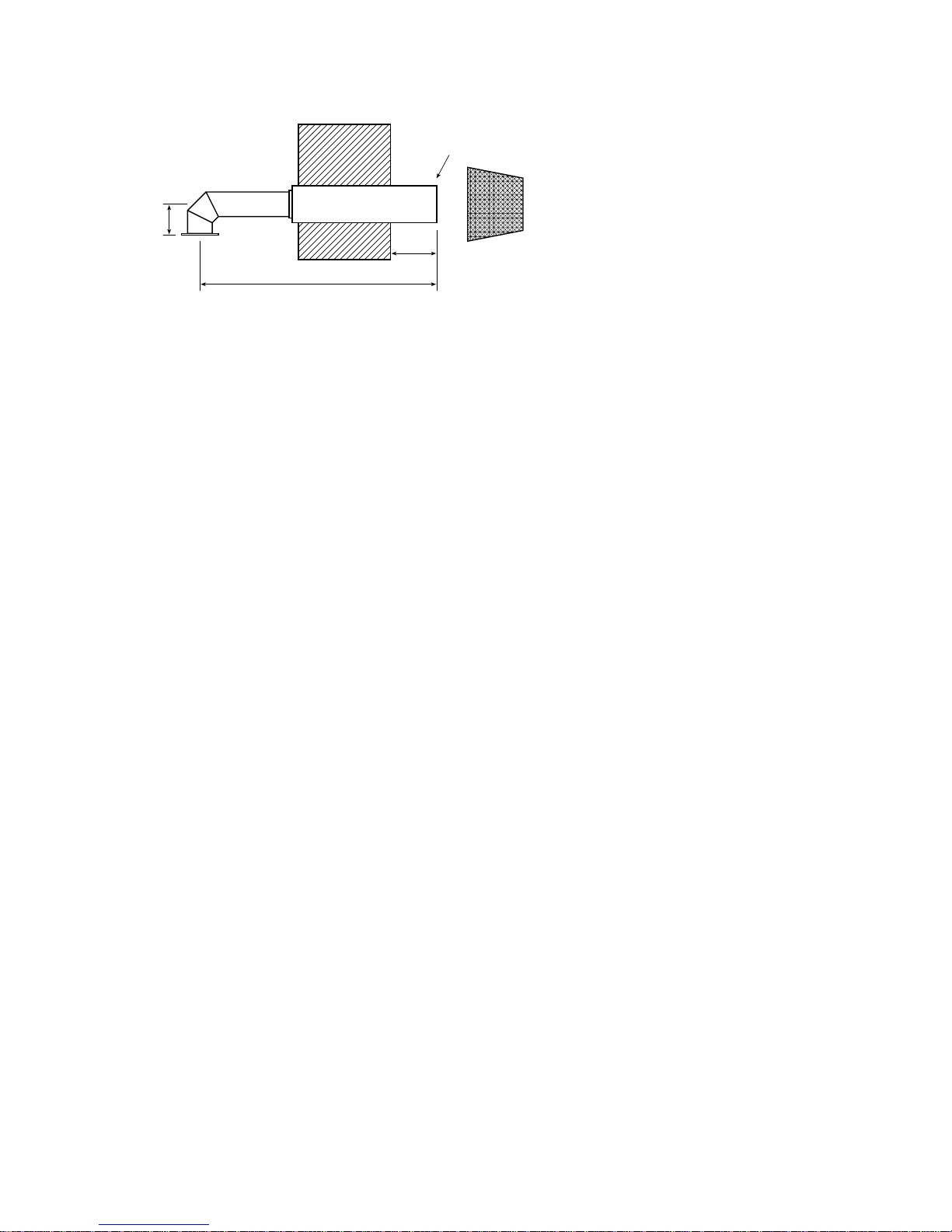
3.3 ‘Easy Fit’ Low Level Conventional Flue (LLF-R)
102
792 MAX
155 MIN
540 MIN
Ø125
225 MAX
4.0 Installation
The boiler installation must be in compliance with BS 5410 and the Building Regulations.
Failure to install and commission in accordance with the instructions contained
within this booklet will invalidate the warranty.
4.1.1 Service Access for WM Boiler (Internal)
600mm clearance should be provided above and in front of the boiler to allow for
routine servicing. If placed under a worktop ensure that the worktop is easily removed.
Additionally the wall mounted boiler requires 200mm beneath the bottom casing and 100
above the top casing as well as 600mm in front to allow clearance for routine servicing.
4.1.2 Servicing WM Boiler (External)
For the external wall mounted boiler there should be a suitable well drained hard
standing area directly in front of the boiler in order to eliminate any risk to the service
engineer or end user from pools of water.
It is recommended that the boiler should not be serviced or the panels removed where
there is a risk of the ingress of water.
Although external wall mounted casing has been weather proofed to IP45 it should not
be subjected to a jet of water from a power washer or hose.
4.1.3 Heating System
The heating system should be installed to HVCA current codes of practice and the
recommendations made in the relevant British Standards.
The use of inappropriate pipe sizes and incorrect plumbing leading to system and boiler
noise is not covered under the boiler warranty.
New and existing systems should be flushed in accordance with BS7593 : 1992
‘Treatment of water in central heating systems’. It is recommended that a non-corrosive
commission cleanser is used when flushing the system.
Note: One 300mm extension piece
may be used to extend the
horizontal length to 1100mm
max and 790mm min.
 Loading...