

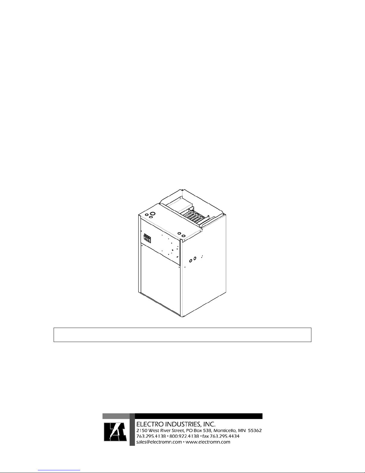
WarmFlo® Electric Furnace
Installation & Operating Instructions
HE-H-**-21 Series
All HE-H-**-21 Electric Furnaces must use an AH chip code. If you have a chip code other than AH, please call
factory for assistance.
Application
Full WarmFlo capability with outdoor sensor. This provides warm air outlet temperature dial selection and supply air
ramp up with the decrease of outdoor temperature. This WarmFlo feature definitely applies to heat pumps, but it is
also the top of the line comfort for straight electric, with air conditioning. The warm air dial suggested setting is 96°
or 100° and the front dial selects the rate of ramp up or temperature increase based upon outdoor. The “C” setting will
provide 114° warm air at 0° or 125° at -20° F outside. The ECM™ blower also ramps up in speed with an increase in
supply temperature or decrease in outdoor tem perature. De pen din g u pon s e t up sel ecti on, t he m oderat e h eat i ng bl o wer
speed could be as low as 50% of full capacity and full capacity blower is only used below 15° outdoor.
Heat/cool conventional or basic heat pump room thermostat can apply.
DO NOT DESTROY THIS MANUAL. PLEASE READ CAREFULLY AND KEEP IN A SAFE
PLACE FOR FUTURE REFERENCE BY A SERVICE TECHNICIAN.
Drawings:
HD320
NC805
NH803
NH804
NH805
NS802
EC001
10/04/2007 NI802

Table of Contents
Configurator 1
General Comments 2
Application 3
Installation Requirements 5
Mechanical Installation 6
Electrical Installation 8
Setup or Programming 11
Operation Indicators 13
Handheld Analyzer/Laptop Software 14
Troubleshooting 14
Replacement Parts 17
10/04/2007 NI802
Configurator
HE-T-KW-CW
Type Cabinet Width
H, A, E, N 21 = 21”
(see below) 24 = 24”*
kW Size
10 = 9.6 kW
15 = 14.4 kW
20 = 19.2 kW*
25 = 24 kW*
30 = 28.8 kW*
Type
All models – ECM™ blower motor, setup selection of four cooling sizes, 50% continuous air (fan – on
setting). High efficient air circulation at about 50-watt.
H = Full WarmFlo capability with outdoor sensor. This provides warm air outlet temperature dial
selection and supply air ramp up with the decrease of outdoor temperature. This WarmFlo
feature definitely applies to heat pumps, but it is also the top of the line comfort for straight
electric, with air conditioning. The warm air dial suggested setting is 96° or 100° and the front
dial selects the rate of ramp up or temperature increase based upon outdoor. The “C” setting
will provide 114° warm air at 0° or 125° at -20° F outside. The ECM™ blower also ramps up
in speed as there is an increase in supply temperature or decrease in outdoor temperature.
Depending upon setup selection, the moderate heating blower speed could be as low as 60% of
full capacity and full capacity blower is only used below 15° outdoor.
Heat/cool conventional or basic heat pump room thermostat can apply.
A = WarmFlo element modulation based upon a warm air set point and duct sensor. Heating blower
speed is installation setup per kW size. A higher CFM selection can be made if there is a desire
to “work” WarmFlo harder.
Heat/cool conventional thermostat applies.
E = Non-WarmFlo, 10, 15, or 20 kW built-in strip heat, direct function of roomstat W. Setup
selection determines nominal ECM™ motor speed. A thermostat “E” type function could be
used to jump to full speed.
N = Cabinet only, no electric elements or WarmFlo. This could typically be associated with an inlet
hydronics water coil. Control board includes a relay for pump, initiated with input W. Setup
selection determines heating blower speed. Cooling speeds and air conditioning interface are
the same as mentioned above.
Note: Two-speed and multi-function room thermostat can also be configured with this system by adding
WF-HP2 interface controller.
10/04/2007 1 NI802

General Comments
Upflow/Downflow/Horizontal
The arrangement of refrigerant coil, hydronics coil, and built-in electric elements need to follow specific
air direction or airflow rules, but the orientation of this Electric Furnace is not critical.
For upflow and horizontal standard air conditioning applications, the A-coil is mounted at the blower
outlet with field provided plenum or AC manufacturer’s case coil.
For upflow heat pump or hydronics applications, factory provided stackable modules are available for
return air filter, hydronics water coil, or heat pump refrigerant coil compartment.
Note: For heat pump the coil must be at the blower inlet.
All models contain GE ECM™ Series 2.3 blower motors. The special Electro Industries interface board
allows hookup for heat/cool conventional or basic heat pump room thermostat. Blower speed setup and
WarmFlo sensor control are separate for cooling and heating (unique).
The ECM™ motor provided in this unit has many features not available in a standard motor.
- Improved efficiency
- Constant CFM
- Soft start and stop
- Better humidity control
The provided ECM™ motor contains permanently sealed bearings and does not require oiling.
Utility Load Control
Provisions are included for the Utility Receiver to interrupt compressor and WarmFlo or strip heat. No
provisions for dual heat, add HP-5046.
Two-Speed Heat Pump
Add WF-HP2 interface controller.
Zone Controller/Dampers
When using models HE-A or HE-H Series there are no adverse electrical heat concerns associated with a
zone damper system. However, there may be an effect on the heat pump compressor due to potential
reduced airflow. The zone dampers themselves must be in the horizontal ducts after the WarmFlo duct
sensor and at least 12” downstream of the WarmFlo sensor.
The zone controller “HVAC equipment” terminal block simply connects to this unit’s control board as if
it was a room thermostat to this unit. If the various zone sizes produce high static pressure and reduced
airflow, the WarmFlo temperature sensing technology will reduce the electric elements automatically.
If the zone damper action has an adverse effect on the heat pump compressor, Electro has zone controller
staging interface for 2-speed heat pump application (WF-HP2, etc.).
Side by Side, with Gas Furnace or Other Dual Heat Arrangements
Add-on dual heat controller HP-5046 can simplify the wiring for dual heat.
For side by side ducting, a motor operated damper is required to isolate the return air between two
blowers. The operation of this motor damper can be controlled from the HP-5046.
10/04/2007 2 NI802

Installation Setup
There are specific peg jumpers relating to cooling tons, heating kW, heat pump reversing valve logic, and
thermostat type. These must be properly evaluated and selected to match each installation.
The “setup or programming” section has all the detailed instructions and selection tables.
The WarmFlo controller also has various dial switch selections relating to duct temperature set point,
minimum warm air set point, HP compressor ODT shutoff temperature, and ramp up efficiency dial.
These are standard WarmFlo technology and setup requirements, if you’re not familiar with WarmFlo
controller study the HD320 WarmFlo information document, also in this package.
NOTICE: When changing any setup jumpers, power down and up. ECM™ motor needs 240V power
and control power removed to reset and reread specific control lines. Open CB number 1 for 10 seconds.
Operation Instructions
The “Operation Indicators” section contains information relating to LED monitor lights, thermostat
sequences, etc.
Installation Checkout
Attached to this manual is a warranty certification and checkout procedure. This must be completed and
returned for warranty coverage. This is the responsibility of the contractor or company which “sold the
job” and is assuming responsibility to the end customer.
Warranty Statement
See the last page of this manual for detailed limited warranty coverage explanation.
Application
General
The configurator, previous page, details several product types. Re-verify nameplate on your received unit
to make sure it properly represents the product type you need for your installation/application.
The setup control board jumpers provide ECM™ blower motor speed flexibility to match the model and
your heat/cool size requirements.
When using with heat pump, must use HE-H Series. Because of WarmFlo’s sensor action and control,
the heat pump coil must be at the inlet side of the blower.
This specific model series, HE-H-**-**
Full WarmFlo capability with outdoor sensor. This provides warm air outlet temperature dial selection
and supply air ramp up with the decrease of outdoor temperature. This WarmFlo feature definitely
applies to heat pumps, but it is also the top of the line comfort for straight electric, with air conditioning.
The warm air dial suggested setting is 96° or 100° and the front dial selects the rate of ramp up or
temperature increase based upon outdoor. The “C” setting will provide 114° warm air at 0° or 125° at 20° F outside. The ECM™ blower also ramps up in speed as there is an increase in supply temperature or
decrease in outdoor temperature. Depending upon setup selection, the moderate heating blower speed
could be as low as 50% of full capacity and full capacity blower is only used below 15° outdoor.
Backup or Assist Wood Heating
This WarmFlo Electric Furnace is ideal for accompanying a wood heating system. The WarmFlo
technology and sensors will determine the Btu/h heating requirement of the building. If the wood warm
air is below the requirement, a small portion (or as required) of the electric elements will come on
automatically supplementing the wood heat.
10/04/2007 3 NI802
Using a wood boiler with the water coil inlet option is an ideal arrangement.
If using a forced wood system, caution must be used when allowing the wood warm air to enter through
the ECM™ motor blower. The maximum temperature for the ECM™ motor is approximately 120° F.
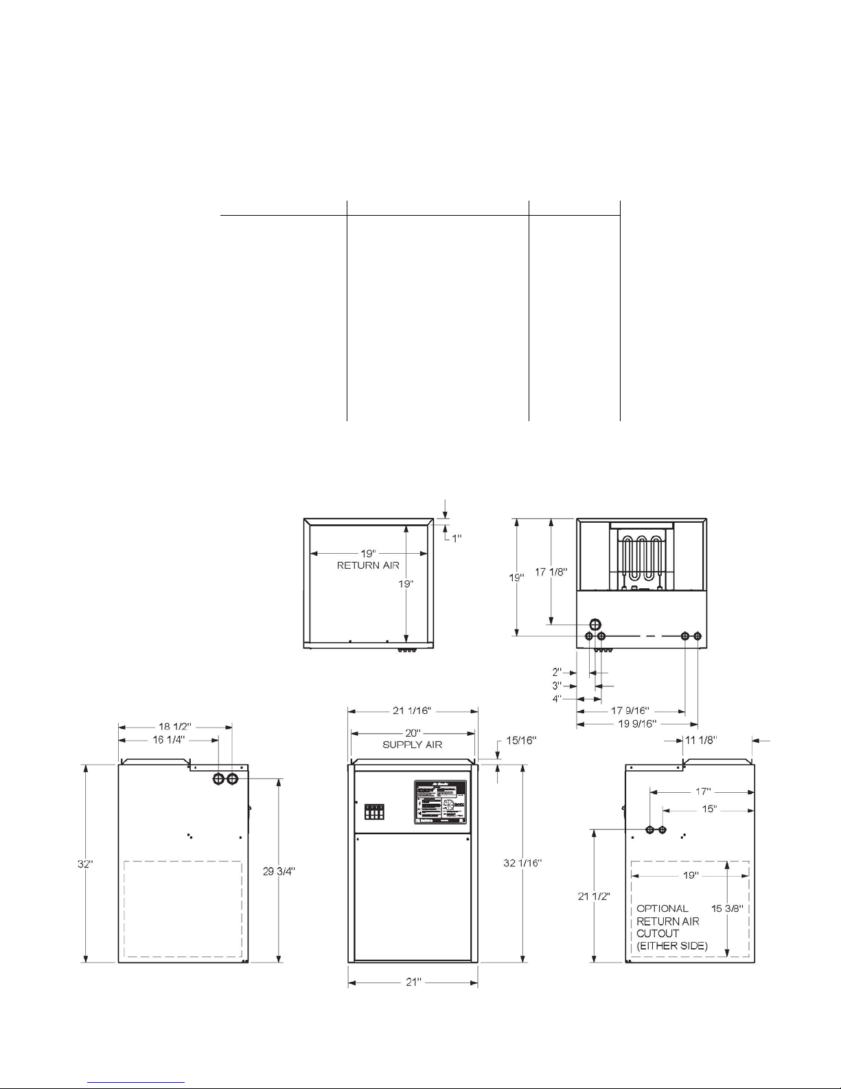
Specification Chart
Model Number HE-H-10-21 HE-H-15-21 HE-H-20-21
Cabinet Width 21” 21” 21”
kW rating 10 15 20
Btu/h 34000 51000 68000
Voltage/Phase 240/1 240/1 240/1
Circuit Breaker 60 1-60, 1-30 2-60
Amps per CB 42 42, 21 42, 42
Source Feed 1 2 2
Elements 4 6 8
Relays 2 4 6
Heat CFM* 765 (LO) 900 (M) 1035 (HI)
Max. Temp. Rise 45° F 45° F 45° F
Shipping Weight
*WarmFlo sensing will override this to 1200 CFM.
Product Dimensions
10/04/2007 4 NI802
Installation Requirements
1. All installation work must be performed by trained, qualified contractors or technicians. Electro
Industries, Inc., sponsors installation and service schools to assist the installer. Visit our web site at
electromn.com for upcoming service schools.
WARNING
ALL ELECTRICAL WIRING MUST BE IN ACCORDANCE WITH NATIONAL ELECTRIC CODE
AND LOCAL ELECTRIC CODES, ORDINANCES, AND REGULAT IONS.
WARNING
OBSERVE ELECTRIC POLARITY AND WIRING COLORS. FAILURE TO OBSERVE COULD
CAUSE ELECTRIC SHOCK AND/OR DAMAGE TO THE EQUIPMENT.
CAUTION
This unit can only be used for its intended design as described in this manual. Any internal
wiring changes, modifications to the circuit board, modifications or bypass of any controls, or
installation practices not according to the details of this manual will void the product warranty,
the CSA/us certification label, and manufacturer product liability. Electro Industries, Inc.,
cannot be held responsible for field modifications, incorrect installations, and conditions which
may bypass or compromise the built-in safety features and controls.
2. If this is a Dual Heat system, this product relates only to the addition to the furnace ducting system
external to the gas or oil force air furnace. The owner/ installer assumes all responsibility and/or
liability associated with any needed installation of the gas/oil furnace, fuel system, flue, chimney, etc.
Any instructions or comments made within this manual (or factory phone assistance) relating to the
gas/oil furnace are provided as comments of assistance and “helps” only.
CAUTION
This unit shall not be operated (either heating section or blower) until the interior of the
structure is completed and cleaned. This also means all duct work must be complete with
filter, etc. Both manufacturers’ warranties are void if this unit is operated during structure
construction.
CAUTION
Hazards or unsafe practices could result in property damage, product damage, severe personal
injury and/or death.
3. Remember, safety is the installer’s responsibility and the installer must know this product well
enough to instruct the end user on its safe use.
Safety is a matter of common sense - - a matter of thinking before acting. Professional installers have
training and experienced practices for handling electrical, sheet metal, and material handling
processes. Use them.
10/04/2007 5 NI802

Mechanical Installation
Clearances and Accessibility
Zero clearance is allowed on all sides for combustible materials. However, 36” should be allowed at the
front for operation, maintenance, and service.
To reduce the risk of rusting and appearance, do not install the unit directly on the ground or on a floor
that is likely to be wet. In such environments the unit must be elevated by use of a sturdy non-porous
material.
General Ductwork and Airflow Requirement
Design the airflow ductwork to meet the maximum operating airflow (CFM) for the kW and cooling ton
requirements (whichever is larger). This document does not provide installation and design information
for the ductwork external to this product. It is assumed this is being accomplished by a professional and
trained installer understanding ductwork design, airflow/static pressure resistance, and forced air
distribution systems. Key requirements information:
- Heating and cooling blower speed or minimum CFM is setup independently. See the “Blower
Speed Selection” to match the airflow capacity with the ducting design.
- The airflow distribution system shall be designed for a maximum of 0.5” SP. Ideally the design
should be set at 0.3” to 0.4” SP.
- The variable speed, ECM™ motor, is sensitive to inlet static pressure. In order for the motor to
arrive at the setup CFM (motor RPM adjust according to static pressure) the inlet must have a
minimum resistance of about 0.15 to 0.2. If you do not have return air ducting and you’re simply
allowing free return air circulation through a filter at this Electric Furnace inlet, you may need to
have a slight restriction in order for the blower motor to arrive at its setup speed.
- All transitions must have a slope of 30° to 45°. There shall be no 90° bends or surfaces causing
airflow bounce/eddy current.
- The manufacturer strongly recommends the return air entering the bottom (under the blower) of
the cabinet. For smaller kW and smaller cooling (10 kW or 2-ton) it is permissible to bring the
air in on either side of the 32” cabinet.
- Previous Specification Chart shows the minimum CFM associated with the kW. Again this is
setup as detailed in the “Setup or Programming” section.
- The cooling CFM is also selected but is not shown on the Specification Chart. In many cases the
airflow distribution system is probably designed to meet the cooling requirement.
- The room registers and individual 5” or 6 “ runs must also match the total setup or planned CFM
for this installation. Typically a 6” round and a typical room register is rated at 100 CFM.
- All distribution ducts (supply and return) must be sized for the setup or planned total CFM
requirement. The attached duct sizing chart shows various distribution duct sizes relating to their
ability to properly handle the stated CFM.
- Seal connections between this unit and ductwork, all ductwork connections, etc. as required to
reduce or eliminate air leakage. Sealing all connections will also reduce air noise.
Comment: The ECM™ motor efficiently relates to system static pressure. On one hand a minimum of
about 0.2” SP is required for the motor to adjust itself, but above 0.3” it begins to drain high current. For
information, consider (at 240):
1.0” SP – 3.4A
0.8” SP – 2.5A
0.5” SP – 0.9A
0.2” SP – 0.4A
Continuous Air – 0.25A
10/04/2007 6 NI802

Whether this unit is sitting on or attached to an inlet cabinet, field designed inlet cabinet, or horizontal
supports; verify proper support and mechanical strength is provided within the system installation.
Rubber isolation pads should be used where possible to reduce sound and vibration transmission.
WARNING
WHEN HANGING THIS UNIT, THERE MUST BE UNDER SUPPORTS WHICH DISTRIBUTE THE
HANGING CHAINS ACROSS THE SURFACE OF THIS UNIT, DO NOT SIMPLY DRI LL A HOLE
AND USE A COUPLE OF HANGING BOLTS.
For information, factory optional inlet cabinets can reduce cost and simplify installation, see NC805.
When installing the unit maintain a minimum clearance of 36” in front of the unit for service accessibility.
Upflow, Air Conditioning
The return air should enter the bottom of this cabinet. Suggest using Electro bottom filter cabinet
(NC805) or field constructed equivalent. The A-coil will be mounted above the blower in either a case
coil or field constructed plenum.
Upflow, Heat Pump
In this case the HP refrigerant coil must be at the bottom of the blower in order for WarmFlo to properly
add temperature to the heat pump output. Electro inlet cabinet is ideal for using a heat pump A-coil
(NC805). This factory available inlet cabinet provides space for standard A-coil and is installed between
the filter/inlet cabinet and the Electric Furnace unit itself.
The cabinet is designed for 20”H A-coil, but for larger A-coils the top can be above this cabinet
approximately 3” (24”).
The outlet of the blower will enter into a plenum and directly into distribution duct.
Downflow, Air Conditioning
Similar to upflow above, the air conditioning coil is positioned at the blower outlet. Depending upon the
coil type and drip pan it is positioned in a field constructed plenum as required.
A typical packaged 20” x 20” filter cabinet could easily be installed at the blower inlet opening.
Downflow, Heat Pump
With the WarmFlo elements down and airflow direction down, the A-coil must be at the top of this unit.
This is assuming the heat pump and associated refrigerant coil you are using is designed to drive air
“backwards” through the A-coil and drip pan. Use heat pump manufacturer’s recommendation; however,
refrigerant coil must be on the inlet side of the elements.
10/04/2007 7 NI802

Horizontal, Air Conditioning
Similar to upflow above, the air conditioning coil is positioned at the blower outlet. Depending upon the
coil type and drip pan it is positioned in a field constructed plenum as required.
As horizontal, the return air would enter the blower end of the cabinet with a typical packaged 20” x 20”
filter cabinet.
Horizontal, Heat Pump
As emphasized above, the heat pump coil must be at the blower inlet. Depending upon the coil physical
arrangements and drip pan, it is installed in a field constructed plenum at the blower inlet.
Typically a package filter cabinet is installed at the entrance (or ahead of) of the HP coil.
The blower outlet goes directly into the distribution duct system.
Blower Motor Orientation
If the installation is not upflow, the blower motor shall be positioned so the power and control connectors
are down. This will prevent water from entering the blower motor through the connector housing
opening.
Loosen motor mount clamp and rotate motor accordingly.
Before tightening motor mount clamp be sure the blower wheel is properly centered inside the blower
housing.
Electrical Installation
WARNING
TO AVOID THE RISK OF ELECTRIC SHOCK OR DEATH, WIRING TO THE UNIT MUST BE
PROPERLY GROUNDED. FAILURE TO PROPERLY GROUND THE UNIT CAN RESULT IN A
HAZARD LEADING TO PERSONAL INJURY OR DEATH.
Line Voltage
The nameplate and/or Installation and Operating Manual specification page provides kW rating and
operating current requirements for each specific model. Select the proper wire size to comply with your
type of wire routing and NEC field wiring requirements.
Field connection is at this product’s furnished circuit breaker. This integrated circuit breaker is a proper
local disconnect.
WARNING
USE ONLY COPPER WIRE FOR CONNECTION TO THE CIRCUIT BREAKER TERMINALS AND
INSIDE THIS PRODUCT’S CABINET.
If the 240 power service is to be wired as single feed, order option circuit breaker single feed bus bar, part
number 5701.
WARNING
DISCONNECT ALL ELECTRICAL POWER BEFORE ELECTRICALLY CONNECTING OR
SERVICING THE UNIT. FAILURE TO DISCONNECT THE ELECTRICAL POWER BEFORE
WORKING ON THIS PRODUCT CAN CREATE A HAZARD LEADING TO PERSONAL INJURY
OR DEATH.
10/04/2007 8 NI802

WarmFlo Controller – Inside View, Left Board
Remote Sensor
Duct sensor, A-coil not in supply plenum – the duct sensor (shorter cable, black wire on ST terminal) is
installed approximately 24” above (or airflow distance from element) the Electric Furnace or electric
elements. Drill a ½” hole, approximately plenum center.
If there is not adequate plenum distance, pick the largest distribution duct and install towards the top of
the horizontal duct. Locate, common sense, in the maximum warm air stream.
Duct sensor, A-coil in supply plenum – the duct sensor (shorter cable, black wire on ST terminal) is
installed on the warm side of the coil and 4” to 6” after the coil. Pick the side which appears to have the
most airflow distribution (facing A-coil) and drill a ½” hole approximately 2” from the side edge.
Again the key is getting this sensor in the maximum warm air stream, the air coming through the A-coil
fins will all be on the edge of the plenum.
Note: The black tip inside of the white tube is the sensor itself. It must be positioned slightly
sticking out of the white tube. The only purpose of the white tube is physical protection, once it
is installed it is okay to push out the sensor ¼” to ½” to make it more sensitive and faster
responding to the warm air stream.
Outdoor sensor – extend sensor to an outdoor location properly sampling the outdoor winter
temperature. The north side may pick up too much shading and winds, but the south side should be
avoided unless there is a position which will shade the sun. Install bracket with the sensor tip up (cable
downward).
Use care in selecting location so the sensor does not pick up false temperature from the heat pump
outdoor unit, from refrigerant line sets, dryer vent, reflection off of steel siding, etc. Also do not install
the sensor in a plastic box because it will falsely trap and pick up radiant sun temperature.
Other Sensor Related Comments
The factory supplied OT cable is 25 feet. If additional cable length is required, you must use the
following rules for extending the cable.
Use unshielded (low capacitance, preferred twisted) 3 or 4-wire low voltage cable.
50 feet is maximum.
Do not, under any circumstances, use leftover wires within the thermostat cable going out to
the outdoor unit.
Route the sensor cable making sure you do not crimp, cut, staple, or damage the cable in any
way.
Keep sensor cables at least 12” away from any line voltage wiring, romex, etc.
For easy sensor cable disconnect and reconnect, the WarmFlo board has a plug-in 4-place terminal block.
Before disconnecting, you will notice two red wires are under one screw and two white wires is under the
COM screw. The black wire represents the data information from each sensor and must be connected to
the appropriate OT or ST screw.
The sensor has polarity, is sensitive to wrong voltage, must be protected from static voltage, etc. Do not
cross connect or inadvertently short out sensor wires with power on. Permanent destruct damage may
result.
10/04/2007 9 NI802

Electric Furnace Control – Inside View, Right Board
There are several room thermostat and outdoor unit possibilities. Pick the following paragraph which
relates to your installation.
Room Thermostat, Air Conditioning
Use conventional heat/cool, 1H/1C, thermostat. It can be mechanical, digital, power robbing, battery
operated, setback, etc. If mechanical, set the heat anticipator to 0.2.
Connect the standard R, W, G, Y stat terminals to the control board HEAT/COOL terminal block with
the same letters.
Room Thermostat, 2-Speed Air Conditioning
Use conventional heat/cool, 2H/2C, thermostat. It can be mechanical, digital, power robbing, battery
operated, setback, etc. If mechanical, set the heat anticipator to 0.2.
Connect the R, W, G stat terminals to the control board HEAT/COOL terminal block with the same
letters.
Connect the Y1 stat terminal to the control board Y1 tab. Connect the Y2 stat terminal to the control
board Y/Y2 screw terminal.
The room thermostat W2 is not used or connected.
Outdoor Unit, Air Conditioning
Connect the outdoor unit 2 wires to the control board Y/Y2 and C. If 2-speed A/C, there will be a third
wire connected to the tab Y1.
Room Thermostat, Heat Pump Single Stage
You must use a basic HP stat with built-in reversing valve function. Typically this will be 6 wires. A
conventional heat/cool (4-wire) thermostat will not work when using a heat pump.
The R and C for the HP thermostat is picked up at the bottom spare 24VAC and COM tabs. The O, G, E,
Y connections are made on the left side bracketed area “HP”.
Outdoor HP Unit (Single Stage)
Typically this unit will have either 4 or 5 wires. The main 4 wires are connected to the screw terminal
block R, Y/2, RV, C. The RV can either be the O or the B wire within the outdoor unit.
If the HP outdoor unit has a 5
tab.
Two-Speed Heat Pump and/or Multi-Wire Heat Pump Thermostat
Add optional interface controller WF-HP2. In this case all room thermostat and outdoor unit hookup is
from the WF-HP2. The HP2 furnace TB connects to this unit stat TB. Use H/C TB and pin jumpers and
R, C, Y1, Y2.
Cooling, Special Dehumidification
The BK tab and the BK peg jumper provide the industry standard 12% blower speed reduction to “pull
out” additional moisture from the air. Provide an external humidistat between BK and R and pull or
permanently disconnect the BK jumper. With the BK terminal at 0 volts the 12% blower speed reduction
is activated.
th
wire for defrost auxiliary heating, connect this 5th wire to the WF (W1)
10/04/2007 10 NI802
 Loading...