

Page 1

Page 2

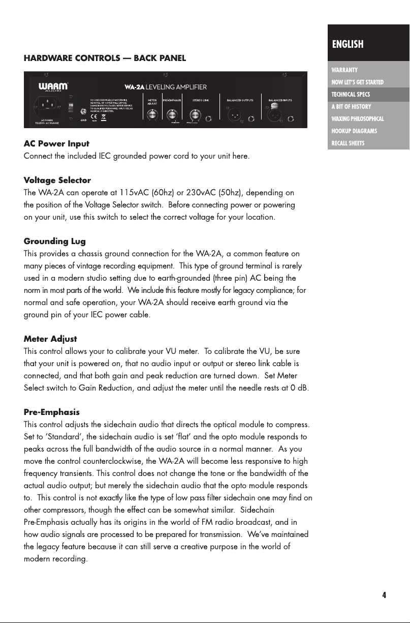
Page 3

Page 4

Page 5
Page 6

Page 7

Page 8

line level, transformer
balanced input
600 ohms impedance pin 2/tip=positive, pin
3/ring=negative, pin 1/sleeve=ground
line level, transformer
balanced output
frequency response +/- 1 DB, 15 HZ TO 20KHZ
maximum gain +40 dB ±1dB
maximum peak reduction -40 dB ±3dB
input level +16 dB maximum
output level +10 dB nominal, +16 dB maximum
distortion Less than 0.1% THD at ±10 dBm
attack time 10 milliseconds
release time 0.06 seconds for 50% release; 0.5 to 5 seconds
tube compliment 2x 12AX7, 1x 12BH7, 1x 6P1 (compatible with
600 ohms impedance pin 2/tip=positive, pin
3/ring=negative, pin 1/sleeve=ground
noise -74dB
for complete release
6aQ5, 6005, and 6N1N)
optical attenuator Kenetek T4B module (socketed) (compatible with T4A,
T4B, and T4C modules per standard wiring
configuration to standard octal header
power 115/230 volts (switchable), 50/60 Hz,
standard IEC 3 conductor cord
fuse compliment 1x 250v, 1amp fast-blow type fuse
dimensions 19” Rackmount chassis, 2U. 19” x 7” x 3.5”
weight 12 lbs
Page 9

CHAPTER 3: A BIT OF HISTORY
In the beginning...
The classic opto-compressor designs date back to at least the late 1950’s; and,
like many pieces of beloved audio gear, has its humble beginnings in the world
of broadcast radio. From there, it was discovered by artists who performed on
radio, and soon made its way into the studio to be used in making records. The
optical compressor represented a step forward in terms of sound quality over
the types of broadcast limiters commercially available at the time; achieving
new levels of perceived transparency and musicality due to its improved THD
and noise specs, and its almost intuitive and program-dependent response. The
earliest versions of this type of compressor had a slower attack time and therefore
were more limited in the types of program material they could handle; however
as the design was perfected throughout the 1960’s, a familiar sonic response
was refined that is still in use today in professional studios around the world.
The optical modules went through several known variations and several different
manufacturers, and include the T4A, T4B, and T4C modules, with many sub-variations
existing within those. Over time, the T4B module became the standard-bearer,
and is the version that continues to be perfected by various makers today.
The optical modules went through several known variations and several different
manufacturers, and include the T4A, T4B, and T4C modules, with many subvariations existing within those. Over time, the T4B module became the standardbearer, and is the version that continues to be perfected by various makers today.
The modules operate by coupling pairs of photo-resistors (resistors which increase
in resistance as they are exposed to light) to an electro-luminescent panel (ELP), with
the luminescent panel being driven by the audio sidechain. The louder the audio’s
transient peak, the brighter the panel becomes, and the amount of resistance
generated by the photo-resistors increases, attenuating the output further. With an
all-tube signal path driving the input, output, and audio sidechain, through large
high quality CineMag transformers - you have the legendary sound of a classic
optical compressor.
Page 10

CHAPTER 4: A LOOK INSIDE
A quick look inside and you will find the WA-2A sports an all discrete, class-A, all tube circuit, using
only through-hole components on a hand-populated board. The WA-2A has a robust power supply
to deliver current to its four vacuum tubes, a socketed Kenetek T4B module (optical attenuator), and large
custom transformers by CineMag.
A Few Words On Tubes
The WA-2A operates on four tubes: two 12AX7’s, one 12BH7, and one 6P1 miniature power tube.
The classic units of the past used a 6aQ5 valve in place of our 6P1; unfortunately the 6aQ5 has
not been manufactured new since the 1980’s. Though still available in smaller quantities as NOS
tubes; we determined there were not enough reliable 6aQ5’s left in the world to go into production
with. One of our early challenges was to find an available tube that had the exact same specifications
and characteristics as the vintage 6aQ5; because we did not want to deviate from the classic design
at all. We finally came upon the 6P1, a tube once used in hi-fi, which is essentially the same tube in
a slightly larger housing with a different pin configuration (in fact, the 6P1 valve has slightly better
specs than the original 6aQ5). To stay true to the classic in every sense, we have placed an original
6aQ5 socket wired directly in parallel next to the 6P1’s socket; so you may in fact replace the 6P1
with an original 6aQ5 if you can obtain an original one in good working order. This will not by
any means improve the performance of the WA-2A and should not be considered an upgrade; but
we have left this option available for the sake of nostalgia and as a testament to the fact that the
original circuit has not been changed.
Known tube substitution list
The two 12AX7 sockets may be populated with any 12AX7 (ECC83), ECC803S (hi-fidelity 12AX7),
or 12AX7A/7025 (low-noise 12AX7). The 12BH7 socket may be populated with any current or NOS
brand of 12BH7. The 6P1 socket may be populated with any 6P1 (Asian) valve or 6N1N (Russian
equivalent). The 6aQ5 socket may be populated with any working NOS 6aQ5 valve or 6005 (high
performance military grade 6aQ5). DO NOT POPULATE BOTH THE 6P1 AND 6aQ5 SOCKETS
AT THE SAME TIME! The 6aQ5 and 6P1 sockets are wired in parallel, and only one socket must be
populated at a time to avoid serious damage to the equipment!
9 6
Page 11

A word on the T4B module
We feel that there is no T4B module finer than those made by Kenetek, and we are
especially proud to offer this high end module in our WA-2A. However, for those who
wish to experiment; we have built our unit in accordance with the standard octal socket
and wiring configuration used for optical compressors for the past half-century. If you
have an old stock T4A, T4B, or T4C module that is in good working order, or a new
one made by another manufacturer; you may install it in the WA-2A to experiment with
different types of modules. Though they all have the same general traits, each have
their own slightly distinct characteristics as far as attack, release, knee, and threshold.
Service Disclaimer
As with all high voltage electronics, all service or modification should be referred to
qualified service personnel only. The WA-2A should be disconnected from mains
power and given time to fully discharge before attempting service or modification.
Aside from vacuum tubes and the T4B module, there are no other aspects of the
WA-2A which are subject to modification; and service should be referred to a qualified
service technician.
Probably no area in the technical side of music production is more hotly debated than
the subject of dynamics control (compression). The so called ‘loudness wars’, which
began far back in the era of vinyl, reached a fever-pitch by the turn of the century
at the height of the Compact Disc; and both engineers and developers sought more
ways to restrict dynamics at every stage of production, from tracking to mixing to
mastering. Experts have called compression the enemy of music, while others have
claimed dynamic range itself to be the enemy. In the end, both answers are right; for
both dynamic restriction and the lack thereof can be quite detrimental to a finished
production. Whatever side of the fence one may be on; it can be generally agreed
that having quality tools for dynamic control when needed, as well as having the skill
to use these tools with good judgment, is vitally important. There are certain styles of
music production, such as jazz and classical, where the use of EQ and compression
are extraordinarily sparse, if used at all. For almost everything else, however, the art
of music production is by and large the creation of something that is a highly enhanced
version of reality. Most especially so with pop and rock music, an engineer’s goal
is to create a finished work that is in most ways ‘larger than life’; creative production
decisions are often made that help lead to a cohesive and consistent finished product,
and that help to captivate and connect the listener to the music on an emotional level.
Page 12

THEORY OF OPERATION
The WA-2A, as with any classic optical compressor, appears deceptively simple at first, with so few
controls on the front panel. The attack, release, knee, and ratio controls found on many other types
of ‘fully comprehensive’ compressors are absent; leaving the user only with a control for compression
threshold (Peak Reduction), makeup gain (Output Gain), and a selection of compress or limit, which
changes the ratio from a starting position of about 4:1 to something closer to 100:1. The WA-2A’s
attack and release characteristics, as well as its ratio and knee, are determined by a very complex
relationship between the optical attenuator and the audio signal being fed into it. Generally, the
WA-2A’s attack will be very fast, with its release character being a rather complex, multi-stage event
that, to an extent, is determined by the audio input and the immediate history of the audio passed
through the module (known as its ‘memory effect’). Generally, the initial release will be very fast,
with a second, more subtle stage of release taking one or more seconds, and a tiny third stage of
release taking even longer. Due to its extended and smooth time constant, this type of compressor
became famous for taming bass guitar, upright bass, and vocals; however, it has the attack speed
and transparency to actually handle many other types of instruments. As with all things audio, let your
ear determine what the music needs and how much compression is enough to achieve your desired
goals. Due to the amount of compression that can achieved; this type of compressor is often a first
choice for instruments that require a fairly strong amount of gain reduction, such as bass; and also
often a first choice for more advanced studio techniques such as series and parallel compression.
Series compression is simply following one compressor/limiter with another one; they do not have
to be the same make or model, but they can be. This is done sometimes when one compressor is
doing much of the heavy lifting of dynamic control, while a second compressor is added because the
engineer favors its particular tonal qualities or ‘glue’. In the case of classic optical compressors, some
engineers have been known to set one unit to a heavier amount of Peak Reduction in Compress
mode, and follow it by a second unit with a much more modest amount of Peak Reduction, set to Li
it mode. This is done to level off any residual transient peaks not caught by the first unit.
Parallel Compression involves using two compressors side by side working on the same input signal.
They do not have to be the same make or model compressor; but they can be. The advent of digital
audio workstation (DAW) recording actually lends itself quite well to this technique. It is now very easy
to duplicate a track in the DAW and send each copy out to individual hardware channels simultaneously,
with no real signal loss. As with series compression, one unit will generally be set much more
aggressively than the other, and the two compressed tracks can be blended back together in the DAW
to achieve a desired effect. When performed properly, one can give a source both the intensity and
presence of a hyper-compressed track, while still retaining the openness, apparent dynamics, and
detail of an uncompressed track. The WA-2A is an ideal choice for this type of compression, due to
the very high levels of gain reduction it can achieve.
Page 13

CHAPTER 5: HOOKUP DIAGRAMS
WA-2A
Recording interface
In this example, a microphone is feeding into a preampflier, which feeds
in to the WA-2A via a balanced XLR patch cable, which feeds in the LINE
LEVEL input of your recording interface/recorder.
Note: it is important to use a line level input on your recording device
as opposed to a microphone or instrument level input.
Page 14

CHAPTER 5: HOOKUP DIAGRAMS
WA-2A
Recording interface
In this example, the WA-2A is being routed as an insert into a recording device. This is useful
for using the WA-2A as an “analog plug-in” or insert for mix-down. The recording device is
feeding the WA-2A with a balanced 1/4” cable via a line output. Then, the recording device
is capturing the WA-2A via a LINE LEVEL input.
13
Page 15

ENGLISH
CHAPTER 6: RECALL SHEETS
WARRANTY
NOW LET’S GET STARTED
TECHNICAL SPECS
A BIT OF HISTORY
WAXING PHILOSOPHICAL
HOOKUP DIAGRAMS
RECALL SHEETS
Page 16

© 2016 Warm AudioTM LLC.
Liberty Hill, Texas USA | www.warmaudio.com
 Loading...