

Page 1

Assault80 Limited Lifetime Warranty
y
War Machine Inc. warranties to initial retail purchaser that the Assault80 paintball marker is free from defects in materials and
workmanship, subject to the limitations of the warranty. Disposable parts (o-rings, batteries, seals etc) are not warranted.
The use of non sanctioned accessories or upgrades is not covered and will void your warranty. This warranty does not cover
aesthetic damages (scratches, dents and nicks) misuse, or improper disassembly and re-assembly, or attempts made to drill
holes, remove metal or modify this product from its original state, which could cause pressure safety factors or degrade the
performance. This warranty does not cover failures due to wear and tear, exposure to the elements or extreme playing
conditions. This warranty is limited to the repair or replacement of defective parts with the customer to pay shipping costs.
This limited lifetime warranty is effective to the original customer with proof of purchase and proper warranty registration. The
warranty is non-transferable. Repair or replacement of defective material is at the discretion of WAR MACHINE INC.
Warranty Claim/Return Policy
For any warranty return/claim needed, please contact our RMA claims department at 1-864-877-1179.
An RMA number must be issued prior to any warranty return. Please be sure to mail your warranty
registration card found in your shipping package for proper registration of your War Machine Product. All
returns will be shipped pre-paid to:
War Machine Warranty Depot
1425 W Wade Hampton Blvd
Greer, SC 29650
Operation of the Assault
80
To get started with your new gun, you should install a bottom line, then make sure the vertical reg
adjustment screw is screwed all the way out (using an 1/8” allen key), so that when an air source is
applied, the reg will be ungassed. Next, check to make certain the 9-volt battery is attached to the grip
frame. Then, from either of the two buttons on the back of the control housing, click and hold for 8
seconds to power on the gun. You will see the color change from red to red/green – this means the gun
is now armed and the safety is off. Attach an air source, and begin to adjust the vertical reg adjustment
screw (clockwise increases, counter-clockwise decreases) until the pressure gauge reads 165-200 psi.
Making sure the barrel plug is in, pull the trigger so that you hear the gun click and fire. You may now
adjust the low pressure reg using an 1/8” allen key – NOTE: this reg has been pre-adjusted from the
factory, however, it may require further adjustment based on your particular requirements. Chrono and
test your marker.
Hint: It’s always a good idea to add a few drops of oil in the input of the gun so that your regs are
properly lubricated.
The Circuit Board
The circuit board on the Assault80 controls the cycling, velocity and the rate of fire of the gun. The
standard Assault
80
circuit board is designed for future EPROM upgrades. The circuit board is located in
the rear upper body of the gun and is accessed through the rear control housing. The standard circuit
board will default to the lowest settings from the factory. The two buttons located on the control housing
determine velocity and rate of fire. The left button controls velocity and the right button controls the rate
of fire. These buttons default to the lowest setting of one each time the gun is powered on. Each button
may be incrementally clicked 1 through 10 clicks to change this setting. After the tenth click, the setting
of these controls are back to the original default position of one. Refer to the Digital Velocity Control
section of this manual for instructions/operations on changing these settings. The circuit board requires
a 9-volt batter
for operation. When low battery conditions occur, inconsistent marker operation occurs.
Page 2

Caution: Never expose electronic components to moisture, static, or magnetic fields, as this will damage
or render the board useless.
Solenoid
The Solenoid is located under the low pressure regulator (LPR) on the front block of the Assault80.
Never exceed 200psi on the high pressure regulator (HPR), as this will damage the solenoid. Never
over tighten the mounting screws – this will distort or damage the component and void the gun’s
warranty.
Cleaning and Lubrication
The anodized parts of the gun should be cleaned off with a damp cloth. DO NOT run the gun under
water to clean, as this will damage the internal electronic components.
The Assault
80
should be cleaned and lubricated after each day of game play. Only O-ring safe oils and
lubricants should be used. The Assault80 regulators require silicon grease and must be kept clean.
Improper lubrication is detrimental to the performance to this gun. Always use War Machine
replacement parts.
Digital Velocity Control
1. Once both regulators are set as described above, you may adjust velocity with the electronic
speed control (ESC).
2. Turn the gun off by pushing either button and holding it down until LED changes from a solid
green to a green/red color (approximately 5 seconds).
3. Turn gun on by pushing and holding either button down until the red color changes to
red/green (approximately 5 seconds).
NOTE: The gun always defaults to the lowest velocity and it’s lowest cycle rate when it is
turned off.
Velocity can now be set by clicking the left hand button from 1 to 10 times. The more the
4.
button is pressed, the higher the velocity. After 10 clicks of this button, the gun will be back in
it’s original default position of one.
CAUTION
: Always use a chronograph to correctly set velocity.
Rate of Fire
The rate of fire can be adjusted between 8 and 13 BPS. Slower rates should be used when using a
loader without a agitation. Faster rates of fire may be used when a motorized loader is used.
1. To adjust the rate of fire, press the right hand button between 1 and 10 times.
NOTE
: The gun always starts as 8 BPS when turned on.
2. To increase rate of fire, continue to press button until the gun loads without breaking balls.
Page 3
3. Higher rates of fire can be achieved by upgrading the circuit board.
Safety ON/OFF
Turning the ASSAULT on:
1. Ensure that a 9-volt battery is installed.
2. Press and hold either button on the back of the gun until the red LED changes to a red/green
combination color (approximately 5 seconds)
NOTE: The LED will blink every 3 seconds to indicate that the gun safety is off and the gun
can be fired.
Turning the ASSAULT off:
1. Press and hold either button on the back of the gun until the green LED changes to a
green/red color (approximately 5 seconds)
NOTE
: The gun is now in the safe mode and cannot be fired.
Propellant Supply
The ASSAULT should use Nitrogen Only.
1.
Pressure into the Assault80 should not exceed 850 PSI.
2.
NOTE: If the assault is to be used on CO2, it is recommended that a bottom line pressure regulator,
remote and an expansion chamber be fitted.
Front Regulator - Low Pressure Regulator (LPR)
Page 4

The front regulator should be set for just below the max press for the solenoid valve (approximately 130
PSI). The front regulator is set too high if air is venting from the hole in the front center of the solenoid
valve. To set:
1. Attach an air source to the gun and adjust the HPR to approximately 180 PSI.
2. Slowly turn the brass screw on the front of the LPR clockwise until air begins to vent out of
the front solenoid valve.
3. Turn the brass screw counter clockwise ½ to ¾ turn. Cycle the gun. The air venting from
the solenoid valve should stop. If it doesn’t, continue to turn screw counter clockwise and
recycle the gun until no air vents from the solenoid valve.
Vertical Regulator - High Pressure Regulator(HPR)
To adjust air source to the gun:
Attach air source to the gun.
1.
2. Turn screw on the bottom of the regulator until approximately 180 PSI is read on the gauge.
Take gun off of safe mode.
3.
4.
Click the electronic speed control (ESC) (located on the left side of the control housing) 10
times.
Fire gun over a chronograph
5.
6. Adjust the velocity with the HPR until deisred velocity is reached.
7. As long as the pressure from the air source remains the same, no further adjustments are
required.
Page 5

Assault80 Parts Diagram
Page 6

Upgrades/How To
Regulator/Supercharger
To assemble your high pressure regulator:
-You will place the Brass Spring Guide into the bonnet (1), and then stack in pairs facing each other, the (10) disc springs,
and insert them on top of the brass guide
-Take the Seat (2) and insert SS Pin through small guide hole on the threaded neck of seat and place greased plunger to
line up with pin. Screw the Seat into the bonnet clockwise until hand tight.
-Apply a small amount of blue loctite to threads on the seat at this time. NOTE: do not use red loctite or any other type
than blue – this allows for disassembly and cleaning of the regulator.
-Take the Reg Body (3) and insert the spring first. Next, drop in the SS Ball, followed by the 90dur o-ring. You will then
screw the body onto the loctite threads of the seat. NOTE: allow this to dry for a couple of hours to prevent leakage.
Also, note that the body has two threaded holes that are not interchangeable – the hole located nearest the top of the
body is for the gauge, while the lower hole (3A) is the input hole. -Lastly, the vertical adapter (4) simply screws onto the
body until hand tight.
Page 7

To disassemble your high pressure regulator:
- Remove the Vertical regulator adapter by turning counterclockwise
- Remove the Body by turning counterclockwise and tap the body to remove the 90dur o-ring, SS Ball, and spring
- Remove the Seat by holding the bonnet in your left hand and carefully turning the seat counterclockwise – you will
remove the plunger and SS Pin
- You will tap the bonnet on a flat surface to remove the disc springs and the spring guide (Note: the (10) disc springs are
concave in shape and must be stacked in pairs facing each other to form a clam shell effect.
Page 8

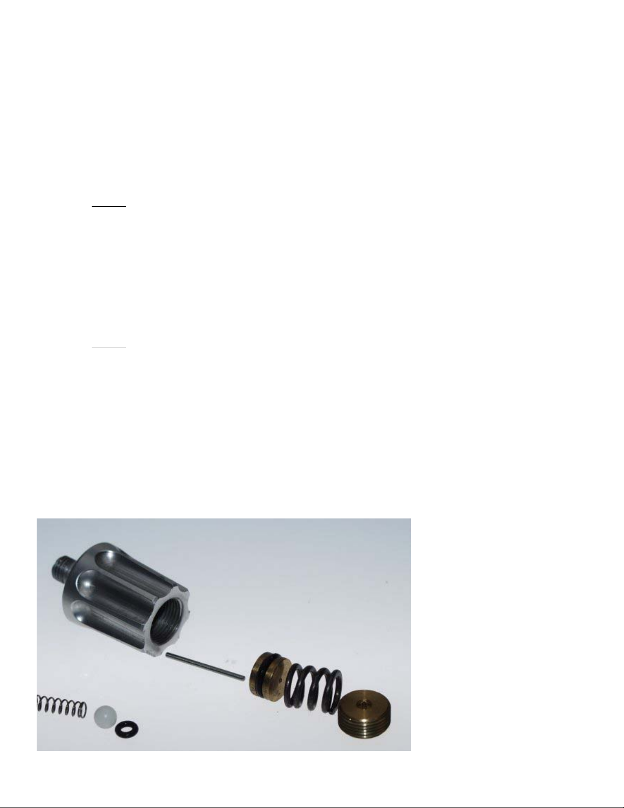
Low Pressure (LPR) Assembly
To outfit your reg with the supercharger upgrade :
Remove the Bonnet by turning counterclockwise
Pull the brass plunger(5A) out of seat, leaving the
SS Pin in place
Remove the brass piston(5A) from the supercharger and note the divet end – place the piston divet hole onto the SS pin
in the seat. Screw the supercharger onto the seat clockwise
Replace the brass plunger into the wide open end of the supercharger with the silver spacer facing up and screw the
bonnet onto the supercharger.
Page 9

Front Block Assembly
2-Stage Low Force Bolt
This is the most advanced ball delivery system created. Firing pressure 70-80 psi. This bolt system
closes
3/4 of the firing stroke at minimum pressure to eliminate ball chopping. The last 1/4 of the bolt stroke
goes full pressure
to lock into closed bolt position until the ball leaves and the cycle is repeated. This is the current
standard on all Assault markers. The LPR will control the first 3/4 of the stroke - approximately 7lbs
closing force.
 Loading...