

Warm2U TH131, TH133 User Manual
TH131 & TH133
User Guide
W2UT-2 (TH131)
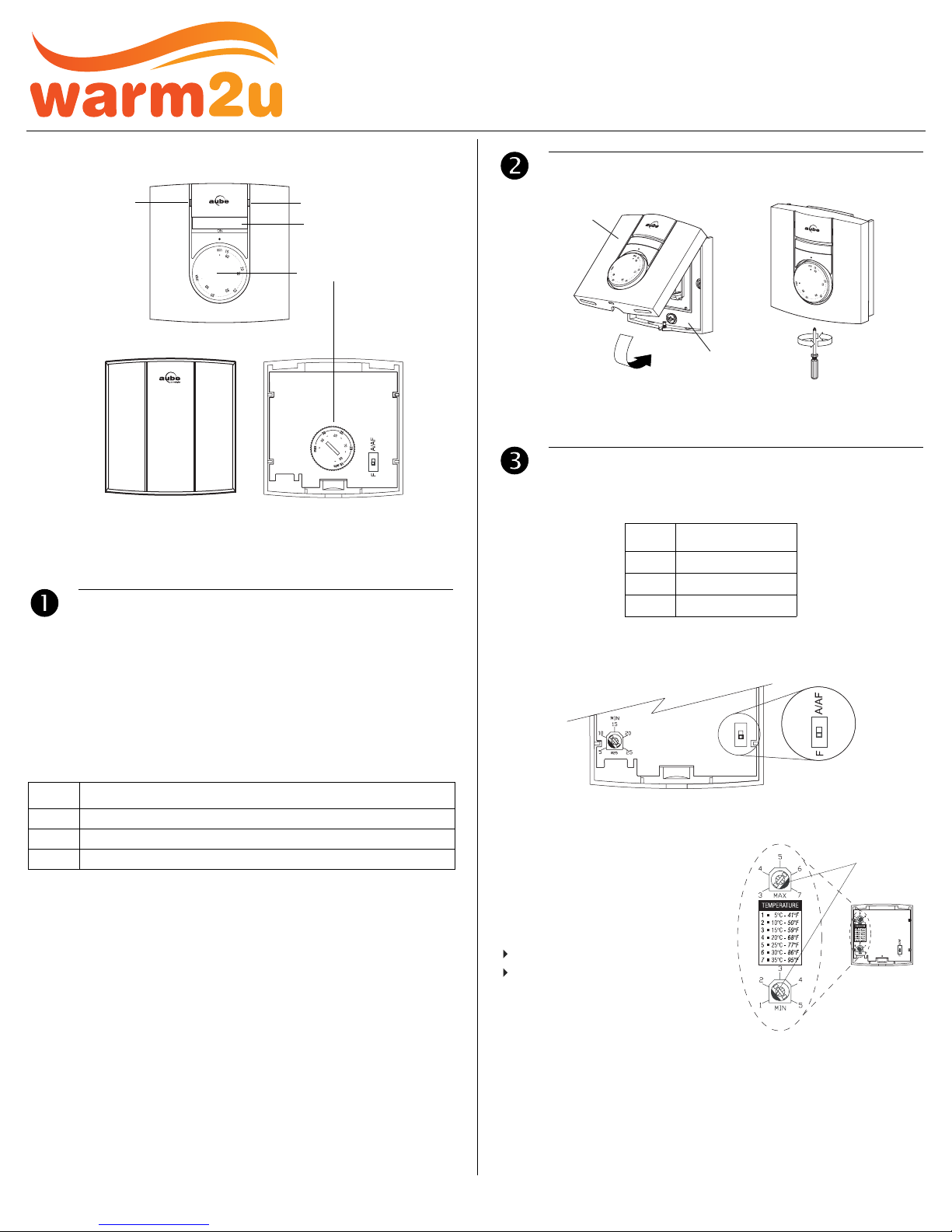
TH131
Pilot wire indicator
(Europe only)
TH133
Front View
NOTE: Even if the following illustrations show the TH131 model only,
they can also apply to the TH133 model.
Description
Heating indicator
On/Off switch
Temperature
selection dial
Rear View
Electronic Thermostat
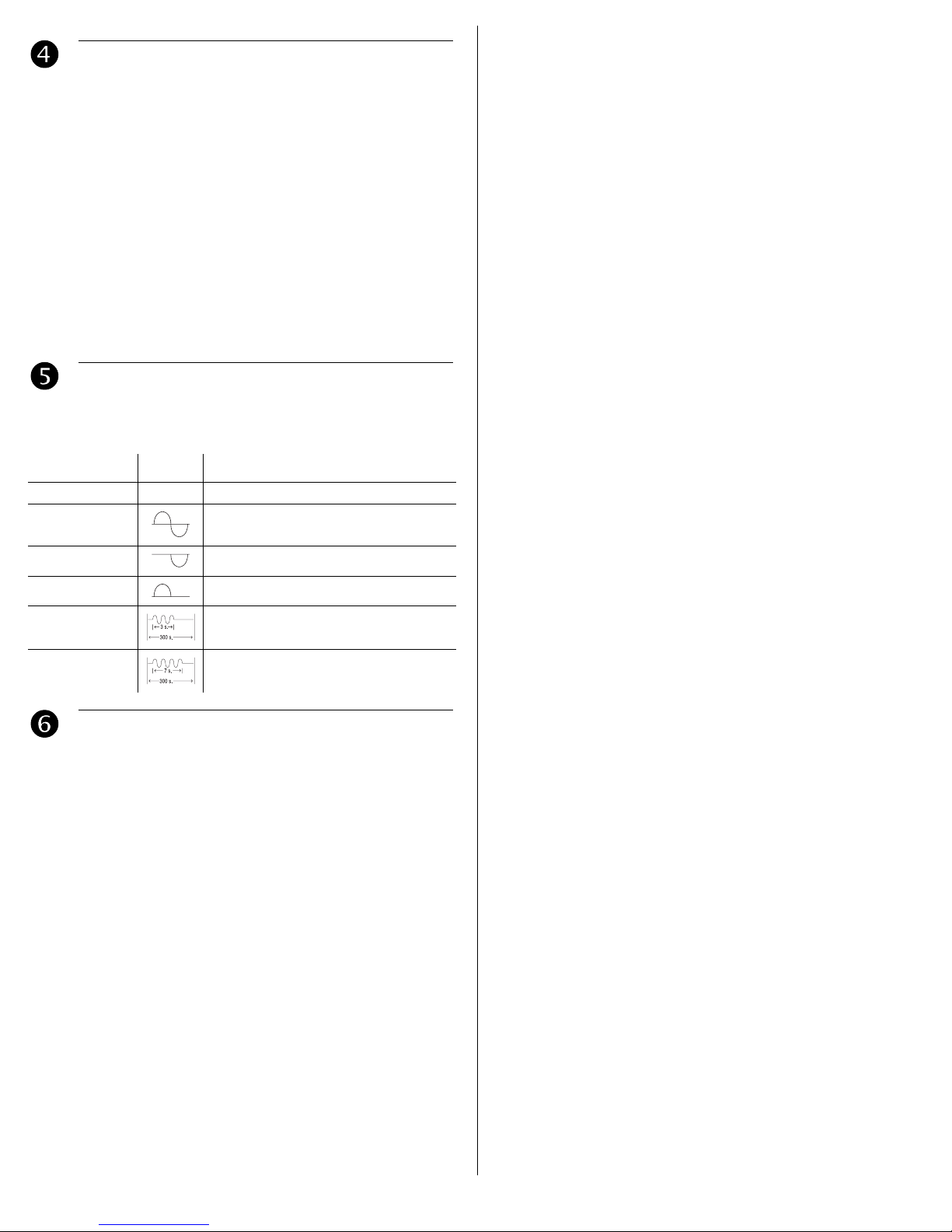
2.
Installation
Control Module
Power Base
NOTE: Keep the thermostat's air vents clean and free from obstructions.
3.
Configuration
3.1 Application Types
Type Switch Position
A UP (A/AF)
1.
AF UP (A/AF)
F DOWN (F)
This user guide covers the following thermostat models:
• TH131 A/F/AF
• TH133 A/F/AF
The TH131 model is designed for residential applications, whereas
the TH133 model is designed for public areas as its controls are hidden and thus protected against unauthorized access. Both models
can be configured for the following applications:
noitacilppAepyT
A Controls the ambient (room) temperature
F Controls the floor temperature
AF Controls the ambient temperature and limits the floor temperature
Position the switch, on the back of the control module, according to
your application.
3.2 Minimum and Maximum Limits (TH131 only)
Use the two potentiometers on the
back of the control module to set
the minimum and maximum temperature limits. Depending on your
application, the potentiometers
limit the following temperature:
ambient temperature (A)
floor temperature (F or AF)
Use a flat-tip screwdriver to rotate
the potentiometers until the notch
points to the desired temperature
limit.
notches
TH131 & TH133 400-131-002-C 1/11/06 1/2
Operation
4.1 Temperature Adjustment
TH131
Use the dial on the front of the thermostat to set the desired temperature.
NOTE: If the dial is placed at a temperature beyond the high or low
temperature limit, the temperature will be maintained at that limit (see
section 3.2).
TH133
Remove the control module from the base and use the dial on the
back of the control module to set the desired temperature.
4.2 On/Off Switch (TH131 only)
Use the On/Off switch to turn the thermostat Off when it is not used
(e.g., in the summer).
Pilot Wire Orders (Europe only)
TH131 accepts the six following pilot wire orders when installed on a
230 V power base.
ORDER SIGNAL DESCRIPTION
Comfort No signal Maintain temperature at setpoint
Reduced setpoint
(3.5k setback)
Maintain temperature at 3.5°C below
setpoint
4.
5.
frost protection Maintain temperature at 7°C
gnitaeh potSffO
1k setback Maintain temperature at 1°C below setpoint
2k setback Maintain temperature at 2°C below setpoint
Specifications
Setpoint range: 7°C, 15°C to 35°C (45°
Minimum temperature limit: 5°C to 25°C (41°F to 77°F)
Maximum temperature limit: 15°C to 35°C (59°F to 95°F)
Accuracy: ± 0.2°C (0.36°F)
Storage: -20°C to 50°C (-4°F to 120°F)
Heating cycle length: 15 minutes
Software: Class A
Controller: Electronic
Size (H/W/D):
• TH131: 78.9 x 78.9 x 16.3 mm (3.1 x 3.1 x 0.64 in.)
• TH133: 78.9 x 78.9 x 18 mm (3.1 x 3.1 x 0.71 in.)
F, 59°F to 95°F)
6.
TH131 & TH133 400-131-002-C 1/11/06 2/2
 Loading...