

Wisotronic 1-channel
Operating instructions
(Keep for future use)
890557_d•en
Photo: Habermaass GmbH
Sun. Light. WAREMA.Valid from 1st July 2014

General information
General information
The publication of this document supersedes all previous corresponding
documentation. We reserve the right
to make alterations in the interest
of technical progress. Considerable
care was taken in producing the text
and graphics in this documentation.
No liability is accepted for any errors
which may nevertheless exist in this
documentation nor for the consequences of any such errors.
Safety instructions
For detailed information, please refer
to the respective installation and operating instructions.
Head office
WAREMA Renkhoff SE
Hans-Wilhelm-Renkhoff-Straße 2
D-97828 Marktheidenfeld
P.O. Box 13 55
D-97828 Marktheidenfeld
Telephone: +49 9391 20-0
Telefax: +49 9391 20-4299
http://www.warema.de
info@warema.de
WAREMA Customer Center
Control systems
Export Department
Tel. +49 9391 20-3740 • Fax -3749
Control systems hotline
Tel. +49 9391 20-6760 • Fax -6769
WAREMA Branch Office
Control systems
Dillberg 33, 97828 Marktheidenfeld
Tel. +49 9391 20-3720 • Fax -3719
Company information
WAREMA Renkhoff SE
Hans-Wilhelm-Renkhoff-Straße 2
97828 Marktheidenfeld/Main, Germany
WAREMA and the WAREMA logo are
trademarks of WAREMA Renkhoff SE.
All other brand or product names
included in this document are trademarks or registered trademarks of
their respective owners.
© 2010, WAREMA Renkhoff SE
2
890557_d•en•01.07.2014

Contents
Contents
1 Legal notes ....................................................................................................... 7
2 Safety instructions ........................................................................................... 8
2.1 Meanings of symbols and pictographs ...........................................................8
2.2 Intended use .........................................................................................................9
2.3 Target group ...................................................................................................... 10
2.4 General safety instructions ............................................................................... 10
2.5 Working safely .................................................................................................... 11
2.6 Retrofitting and modifications .......................................................................... 12
2.7 Additional documents ....................................................................................... 12
2.8 Basic software versions .................................................................................... 12
3 Introduction .................................................................................................... 13
3.1 Operating elements ........................................................................................... 13
3.2 Menu elements ................................................................................................... 14
3.2.1 Display of the products .............................................................................. 16
3.3 Principal structure of a Wisotronic system .................................................... 17
3.4 Concept ............................................................................................................... 18
3.4.1 Channels, facades and products ............................................................ 18
3.4.2 Groups ........................................................................................................... 19
3.4.3 Scenes ........................................................................................................... 19
3.4.4 Safety, comfort and basic functions ......................................................... 20
4 Menu structure ............................................................................................... 21
4.1 Main menus ........................................................................................................ 21
4.2 Convenience functions...................................................................................... 22
4.3 Safety functions .................................................................................................. 23
4.4 Manage channels, groups, scenes ................................................................ 23
4.5 System ................................................................................................................. 24
5 Getting started ................................................................................................ 25
5.1 Start menu ........................................................................................................... 25
5.1.1 Status display ............................................................................................... 26
5.2 Main menu .......................................................................................................... 27
5.3 Example for operation: Set time and date .................................................... 28
5.4 Example for operation:
Set display ........................................................................................................... 29
6 Manual operation ........................................................................................... 31
7 Set functions .................................................................................................. 33
7.1 Basic functions ................................................................................................... 33
7.1.1 Sun control ON/OFF ................................................................................... 33
7.1.2 Brightness ..................................................................................................... 34
7.1.3 Movements .................................................................................................... 34
7.1.4 Dawn/dusk control ON/OFF ..................................................................... 34
7.1.5 Dawn/dusk .................................................................................................... 34
7.1.6 Temperature control ON/OFF.................................................................... 35
7.1.7 Temperature .................................................................................................. 35
7.1.8 Precipitation monitor ON/OFF ................................................................... 35
7.1.9 Intermittent ventilation ................................................................................. 35
7.1.10 Time switch ................................................................................................... 36
7.1.11 Wind monitoring ........................................................................................... 36
7.1.12 Ice monitor .................................................................................................... 36
7.2 Convenience functions...................................................................................... 37
7.2.1 Sun control .................................................................................................... 37
7.2.1.1 Sun control ON/OFF ............................................................................. 38
7.2.1.2 Limit value SUN ..................................................................................... 38
890557_d•en•01.07.2014 We reserve the right to carry out improvements
3

Content Wisotronic 1-channel
Operating instructions
7.2.1.3 Delay SUN .............................................................................................. 38
7.2.1.4 Position SUN .......................................................................................... 38
7.2.1.5 Slat angle SUN ....................................................................................... 38
7.2.1.6 Limit value CLEAR ................................................................................. 39
7.2.1.7 Delay CLEAR .......................................................................................... 40
7.2.1.8 Position CLEAR ...................................................................................... 40
7.2.1.9 Slat angle CLEAR .................................................................................. 40
7.2.1.10 Limit value CLOUD ................................................................................ 40
7.2.1.11 Delay CLOUD ......................................................................................... 41
7.2.1.12 Position CLOUD ..................................................................................... 41
7.2.1.13 Slat angle CLOUD ................................................................................. 41
7.2.1.14 Limit values of the sun control ............................................................ 41
7.2.1.15 Active during leave? .............................................................................. 42
7.2.1.16 Active during absence? ........................................................................ 42
7.2.1.17 Measured value photo .......................................................................... 42
7.2.1.18 Correct use of the sun control ............................................................ 42
7.2.1.19 The sun control during a wind, precipitation or ice alarm ............. 43
7.2.2 Dawn/dusk control ...................................................................................... 44
7.2.2.1 Dawn/dusk control ON/OFF ............................................................... 45
7.2.2.2 Limit value DAWN .................................................................................. 45
7.2.2.3 Position DAWN ....................................................................................... 45
7.2.2.4 Slat angle DAWN ................................................................................... 45
7.2.2.5 Auto control DAWN ............................................................................... 46
7.2.2.6 Limit value DUSK ................................................................................... 46
7.2.2.7 Position DUSK ........................................................................................ 46
7.2.2.8 Slat angle DUSK .................................................................................... 46
7.2.2.9 Auto control DUSK ................................................................................ 47
7.2.2.10 Active during leave? .............................................................................. 47
7.2.2.11 Active during absence? ........................................................................ 47
7.2.2.12 Measured value dawn/dusk ................................................................ 47
7.2.2.13 Automatic status .................................................................................... 47
7.2.2.14 Auto control status ................................................................................ 47
7.2.2.15 Using dawn/dusk control correctly .................................................... 48
7.2.2.16 The dawn/dusk control during a wind or ice alarm ...................... 48
7.2.3 Temperature control .................................................................................... 49
7.2.3.1 Basic functions....................................................................................... 50
7.2.3.2 Temperature control ON/OFF ............................................................. 51
7.2.3.3 Limit value WARM ................................................................................. 52
7.2.3.4 Position WARM ...................................................................................... 52
7.2.3.5 Slat angle WARM ................................................................................... 52
7.2.3.6 Limit value COLD ................................................................................... 52
7.2.3.7 Position COLD ........................................................................................ 53
7.2.3.8 Slat angle COLD .................................................................................... 53
7.2.3.9 Operating mode, selecting .................................................................. 53
7.2.3.10 Number of levels ................................................................................... 54
7.2.3.11 Maximum level ....................................................................................... 55
7.2.3.12 Step duration .......................................................................................... 55
7.2.3.13 Difference temperature control ........................................................... 55
7.2.3.14 Active during leave? ............................................................................ 60
7.2.3.15 Active during absence? ...................................................................... 60
7.2.3.16 Measured value temperature ............................................................. 60
7.2.3.17 Measured value outside temp. ............................................................ 60
7.2.4 Precipitation monitor ................................................................................... 61
7.2.4.1 Precipitation monitor ON/OFF ............................................................ 61
7.2.4.2 Off delay .................................................................................................. 62
7.2.4.3 Position PRECIPITATION ...................................................................... 62
7.2.4.4 Slat angle PRECIPITATION .................................................................. 62
7.2.4.5 Active during leave? .............................................................................. 62
7.2.4.6 Active during absence? ........................................................................ 63
7.2.4.7 Meas.value precipitation ...................................................................... 63
7.2.5 Intermittent ventilation ................................................................................. 64
7.2.5.1 Intermittent ventil. ON/OFF ................................................................. 64
7.2.5.2 Ventilation duration hh:mm .................................................................. 64
We reserve the right to carry out improvements
4
890557_d•en•01.07.2014

Contents
7.2.5.3 Break duration hh:mm .......................................................................... 65
7.2.5.4 Ventilation step ....................................................................................... 65
7.2.5.5 Active during leave? .............................................................................. 65
7.2.5.6 Active during absence? ........................................................................ 65
7.2.6 Time switch ................................................................................................... 66
7.2.6.1 Time switch ON/OFF ............................................................................ 67
7.2.6.2 ST1: switch time hh:mm ....................................................................... 68
7.2.6.3 ST1: position........................................................................................... 68
7.2.6.4 ST1: Slat angle ....................................................................................... 68
7.2.6.5 ST1: Auto control ................................................................................... 68
7.2.6.6 ST2: switch time hh:mm ....................................................................... 69
7.2.6.7 ST2: position........................................................................................... 69
7.2.6.8 ST2: Slat angle ....................................................................................... 69
7.2.6.9 ST2: Auto control ................................................................................... 69
7.2.6.10 ST3 and ST4 .......................................................................................... 70
7.2.6.11 Automatic status .................................................................................... 70
7.2.6.12 Auto control status ................................................................................ 70
7.2.6.13 Active during leave? .............................................................................. 70
7.2.6.14 Active during absence? ........................................................................ 70
7.2.7 Cold protection ............................................................................................. 71
7.2.7.1 Cold protection ON/OFF ...................................................................... 71
7.2.7.2 Blocking temperature ........................................................................... 71
7.2.7.3 Position COLD ........................................................................................ 71
7.2.8 Leave .............................................................................................................. 72
7.2.8.1 Position .................................................................................................... 72
7.2.8.2 Slat angle ................................................................................................ 72
7.2.9 Absent ............................................................................................................ 73
7.2.9.1 Position................................................................................................... 73
7.2.9.2 Slat angle ................................................................................................ 73
7.2.9.3 Current state absent ............................................................................. 73
7.2.10 Manual operation ......................................................................................... 74
7.2.10.1 Position DOWN ...................................................................................... 74
7.2.10.2 Slat angle DOWN .................................................................................. 74
7.2.10.3 Holding time hh:mm.............................................................................. 75
7.2.10.4 The manual operation options ............................................................ 75
7.2.11 Hand-held transmitter allocation ............................................................... 76
7.2.11.1 Hand-held transmitter 1 ........................................................................ 77
7.2.11.2 Hand-held transmitter 2,3,4 ................................................................. 77
7.2.11.3 Hand-held transmitter identifier ........................................................... 77
7.3 Manage channels, groups, scenes ................................................................ 78
7.3.1 Manage groups ............................................................................................ 78
7.3.2 Manage scenes............................................................................................ 79
7.3.2.1 Scene selection ..................................................................................... 80
7.3.2.2 Change scene name ............................................................................ 80
7.3.2.3 Hand-held transmitter allocation ......................................................... 81
7.3.2.4 Delete scene .......................................................................................... 81
7.3.2.5 Holding time hh:mm.............................................................................. 81
7.3.2.6 Scene member 1 ................................................................................... 81
7.3.2.7 Scene member 2 to 4 .......................................................................... 81
7.3.3 Sort channels, groups, scenes ................................................................. 82
7.3.4 Change alias names ................................................................................... 82
7.4 Leave time ........................................................................................................... 84
7.4.1 Leave begin dd.mm .................................................................................... 84
7.4.2 Leave end dd.mm ........................................................................................ 84
7.5 System settings .................................................................................................. 85
7.5.1 Date / time .................................................................................................... 86
7.5.2 Display ........................................................................................................... 87
7.5.2.1 Brightness at standby .......................................................................... 87
7.5.2.2 Brightness at operation ....................................................................... 87
7.5.2.3 Button tone ............................................................................................. 88
7.5.2.4 Standbyduration ..................................................................................... 88
7.5.2.5 Display behaviour of Wisotronic ......................................................... 88
890557_d•en•01.07.2014 We reserve the right to carry out improvements
5

Content Wisotronic 1-channel
Operating instructions
7.5.2.6 Colour scheme ...................................................................................... 89
7.5.3 Measured values start menu ..................................................................... 90
7.5.4 Language ...................................................................................................... 91
7.5.5 Sensor compensation ................................................................................. 92
7.5.5.1 Control panel temperature ................................................................... 92
7.5.5.2 Weather station 1 (2,3) outside temperature ................................... 92
7.5.6 Wind test ....................................................................................................... 93
7.5.7 Restore settings ........................................................................................... 93
7.5.8 Software versions ........................................................................................ 94
7.6 Sensor allocation ............................................................................................... 95
7.7 Clean control panel ........................................................................................... 95
7.8 Service ................................................................................................................. 96
7.9 Safety functions .................................................................................................. 96
7.9.1 Wind monitoring ........................................................................................... 96
7.9.2 Ice monitor .................................................................................................... 97
7.9.2.1 Automatic reset ice alarm? .................................................................. 97
7.9.2.2 Manual reset ice alarm? ....................................................................... 98
7.9.2.3 Measured value outside temp. ............................................................ 98
7.9.2.4 Meas.value precipitation ...................................................................... 98
8 Measured values, triggers and faults ........................................................... 99
8.1 Current measured values ................................................................................. 99
8.2 Measured values history ................................................................................. 100
8.3 Current triggers ................................................................................................101
8.4 Trigger history ................................................................................................... 102
8.5 Faults ..................................................................................................................103
9 Cleaning ........................................................................................................ 104
10 Maintenance ................................................................................................. 104
11 Disposal ........................................................................................................ 104
12 Liability .......................................................................................................... 105
13 Information for the user ............................................................................... 105
14 Troubleshooting ........................................................................................... 106
15 Technical data .............................................................................................. 108
16 Index ............................................................................................................. 109
We reserve the right to carry out improvements
6
890557_d•en•01.07.2014

Introduction
The Wisotronic is a multifunctional sun shading control system that can con-
trol the various sun shading products (slat products, fabric products, roller
shutters, window drives, etc.) in an intelligent manner and according to the
current weather conditions.
You can either operate your sun shading products manually or leave operation entirely in automatic control mode. The Wisotronic shields your sun
shading against damaging weather conditions and offers a comprehensive
range of comfort and safety functions. In addition, the Wisotronic can be operated via EWFS transmitters; the radio receiver was integrated in the control
panel.
The Wisotronic evaluates data regarding:
Wind,
Precipitation,
Brightness,
Inside and outside temperature,
Time
And, based on these results, controls the connected Sun City products such
as slack products (external and internal venetian blinds), fabric product (awnings, pleated blinds), vertical louvre blinds, black-out systems, roller shutters
and window drives.
1 Legal notes
Operating instructions, manuals and software are protected by copyright.
890557_d•en•01.07.2014 We reserve the right to carry out improvements
7
Safety instructions
2 Safety instructions
2.1 Meanings of symbols
and pictographs
Wisotronic 1-channel
Operating instructions
We have developed and tested the Wisotronic in compliance with the basic
safety requirements.
Nonetheless, some risks remain.
For this reason, please read these instructions before commissioning and
operating the control.
It is very important to adhere to the safety information listed here and the
warning information in these instructions. Otherwise, any warranty claims
against the manufacturer become void.
Keep these instructions for future use.
The safety information in these instructions is marked with warning symbols.
It is categorised into different warning types depending on the level of potential danger:
DANGER
warns of an imminently dangerous situation.
Possible consequences may include serious injuries and even death
(personal injury), property or environmental damage.
WARNING
warns of a potentially dangerous situation.
Possible consequences may include light or serious injuries and even
death (personal injury), property or environmental damage.
CAUTION
Reminder to be careful. Possible consequences of the failure to do so may
include property damage.
The following pictograms and symbols may be affixed to the control unit itself
or to the connected devices, alerting you to potential danger:
WARNING
Warning against dangerous electrical voltage.
NOTE The term NOTE marks important notes and helpful tips.
We reserve the right to carry out improvements
8
Example The term Example marks an example.
The square marks an instruction or a prompt for action. Perform this step.
The triangle marks an event or the result of a preceding action.
The black triangle is a bullet point for lists or selections.
890557_d•en•01.07.2014

2.2 Intended use
Safety instructions
For each channel, the Wisotronic enables the connection of one conventional
sun shade drive with a single-phase AC motor. Alternatively, multiple sun
shade drives can be connected via motor control units.
WARNING
Please obtain the approval of the manufacturer if you have questions
regarding the connection of devices not listed in these instructions.
All control devices are intended to be installed indoors unless otherwise
specified.
CAUTION
When using window drives, the installer of the system must ensure that
the safety regulations and precautions of DIN EN 60335-2-103 "Special
requirements on drives for gates, doors and windows" as well as ZH 1/494
"(German) guidelines for power-operated doors, windows and gates" are
observed.
WARNING
The Wisotronic may only be used to control such window drives where the
movement of the window cannot cause any injuries!
These windows include (partial list), according to DIN EN 60335-2-103:
Windows with moving parts located at least 2.5m above the floor or other
access levels.
Windows with drives equipped with an external or internal entrapment protec-
tion system.
Windows with an opening speed that does not exceed 50 mm/s when
moving between 15 mm and 50 mm away from the closed position, with a
maximum opening width of 200 mm and with a closing speed that does not
exceed 15 mm/s.
WARNING
The approval of the manufacturer must be obtained for uses outside of the
purposes listed here. The consequences of unintended use may include
personal injuries of the user or of third parties as well as property damage
to the control itself, to connected devices or moveable mechanical parts
of the entire system.
Therefore, use our product only as intended.
890557_d•en•01.07.2014 We reserve the right to carry out improvements
9
Safety instructions
2.3 Target group
2.4 General safety
instructions
Wisotronic 1-channel
Operating instructions
These instructions are addressed to persons operating, adjusting or commissioning the control unit. The installation instructions (art. no. 890424) are
available for persons installing, wiring or establishing a mains connection for
the Wisotronic, including all necessary parts.
WARNING
Operation by persons who are not sufficiently qualified and informed can
cause severe damage to the system or may even cause personal injury.
Commissioning may therefore only be performed by properly trained and
qualified specialists. These technicians must be able to recognize sources of
danger that may be caused by the mechanical, electrical or electronic equipment.
These qualified technicians must know and understand the content of these
instructions.
The control system controls your sun shading product automatically. You
must therefore observe the following safety instructions:
WARNING
An automatically controlled mechanism can start moving unexpectedly.
Therefore, never place any objects in the area of movement of an automati-
cally controlled mechanism.
If measuring or test work needs to be carried out on the active system, make
sure that applicable accident prevention regulations are observed under all
circumstances.
CAUTION
An automatically controlled sun shading system (e.g., roller shutter on
a balcony door) can move down automatically and lock you out. If the
Wisotronic of these types of roller shutters has an automatic control, you
should always "play it safe" and switch it off temporarily before going outside.
CAUTION
The entire system becomes non-functional if power fails. Therefore, move
your sun shading system to a safe position ahead of time if a storm is
pending.
WARNING
Children must not play with this product – remote controls or EWFS
transmitters must not get into the hands of children.
We reserve the right to carry out improvements
10
890557_d•en•01.07.2014
2.5 Working safely
Safety instructions
WARNING
The electrical installation must be performed by a certified electrician in
accordance with the electrical installation regulations published by the
Association of German Electrical Engineers (VDE 0100) or the standards
and regulations of the country in which the device is being installed. The
electrician must observe the installation instructions included with the
electrical device.
If you want to perform work on motor-operated windows or building façades
where motor-operated sun shading products are installed, then
Switch the system to a de-energised state.
Make sure that the unit has been sufficiently secured against unauthorised or
unintentional reactivation.
In any case, use suitable safety devices for personal protection.
Never place or store any items in the motion area of automatically operated
mechanisms (e.g. ladder against a house wall with an articulated arm awning).
WARNING
Dangerous situations, malfunctions and property damage to the unit
may result from improperly executed mounting, connection, repair or
maintenance work.
Such work may only be carried out by the service department or by author-
ised qualified personnel.
Only use such spare/replacement parts for maintenance or repair work as
have been approved by the manufacturer of the unit.
WARNING
Dangerous situations, malfunctions and property damage to the unit may
result if connections are disconnected during operation! All connections
are required for proper operation of the control.
Therefore, switch off the entire system before attaching or detaching connect-
ing lines.
WARNING
Danger to life and property damage through sudden movement of the
mechanism!
890557_d•en•01.07.2014 We reserve the right to carry out improvements
11
Safety instructions
2.6 Retrofitting and
modifications
Wisotronic 1-channel
Operating instructions
We have designed and built the Wisotronic with reliability and safety in mind.
All required settings are made when the unit is first commissioned. Modification of the unit parameters is therefore only required when the characteristics
of the control need to be adjusted, changes are made to the sensor equipment or the control itself is replaced.
WARNING
Retrofitting and modifications may impact the safety of the system or
reduce its effectiveness. Possible consequences may include death,
serious or light injuries, and property or environmental damage.
Therefore, contact us or your specialist dealer before retrofitting or changing
the system or the unit parameters if you cannot find information on the corresponding topic in the control unit documentation. This is the only way to
ensure trouble-free retrofitting/modification.
Exercise special care when components of different versions are combined
or when existing components are replaced by older/newer products with a
different scope of functions or a different software version.
2.7 Additional documents
2.8 Basic software
versions
The following documents are available in addition to these instructions:
Document Number
Wisotronic 1-channel installation instructions 890558
Wiring diagrams for MSE, power supply unit and floor distribution
control
Operating and installation instructions of the connected components (e.g. weather station)
These instructions were created on the basis of the software versions:
Product Version
Wisotronic control panel 39402108
Wisotronic actuator 39413107
Chapter7.5.8 Software versions of these operating instructions contains information on how you can determine the software version of your control.
816345
-
We reserve the right to carry out improvements
12
890557_d•en•01.07.2014

3 Introduction
3.1 Operating elements
Introduction
The Wisotronic stands out by its elegant design as well as an especially userfriendly user interface. The presentation of all setting steps and measuring
values is provided in plain text in a clearly arranged display window, simply
referred to as "Display" in this document. The resolution is 240 x 320 pixels
in 256 colours and the illumination ensures easy readability by a highcontrast display.
The equipment features of the Wisotronic:
flat and elegant design housing with noble acrylic glass front cover, 4 sensor
function buttons and a touch wheel
graphic display
integrated EWFS receiver
integrated temperature sensor
Fig. 1 The Wisotronic operating elements
Display
The illuminated display informs you on everything you can view and set
on the Wisotronic. For example, you can view the current measured values of the outside brightness and outside temperature, the current time
and much more. The various elements of the display are explained in
Chapter 3.2 on page 14.
B
Function buttons
Depending on the information on the display, different processes can be
triggered with the function buttons. For example, you may jump to the main
menu, restore a preset value, cancel an input, and more.
C
Touchwheel
The touch wheel can be used to select and open menus, channels, groups
and scenes or current weather data and measuring values in the display.
Simply move a finger along the circular depression (clockwise or anticlockwise). When you press the middle of the touch wheel, a preselected menu
item opens, for example, or a modified value is accepted.
890557_d•en•01.07.2014 We reserve the right to carry out improvements
13
Introduction
3.2 Menu elements
Wisotronic 1-channel
Operating instructions
An overview of the menu elements is provided below. The menus are generally structured as shown in the following example.
The header on the very top shows you the menu in which you are located.
This is followed by six menu lines whereby each line represents a value. The
designation of the setting value is shown on the left side, and the current
value is shown on the right. The selected menu line is highlighted in colour.
If the text is shown in a black line (or if the colour scheme is bright white),
this setting cannot be selected because it does not apply to the selected
product or this function was switched off in another menu item.
A narrow scroll bar on the right edge of the screen indicates the section of
the menu in which you are located and whether further menu items exist.
Turning the touch wheel clockwise moves the selection bar downward and
turning it anticlockwise moves the bar up. If the menu has more than six lines
(indicated by the scroll bar at the right of the screen), all lines move down or
up and additional settings values become visible.
When the middle of the touch wheel is touched, the colour of the setting in
the selected line changes. This means that the value can now be set by turning the touch wheel.
In the footer on the bottom you will see four fields with functions. They are
located above the four function buttons and can be activated by touch. The
commands change depending on the menu and menu item shown. In the
example shown, you can use the [Main] function button to open the main
menu. Press the [Back] function button to return to the higher level menu.
We reserve the right to carry out improvements
14
890557_d•en•01.07.2014
Introduction
After you have set a desired value, you must press the touch wheel. This
causes this value to be adopted and the setting changes to the original colour. Another turn of the touch wheel does not cause the value to change but
moves the selection bar up or down once more.
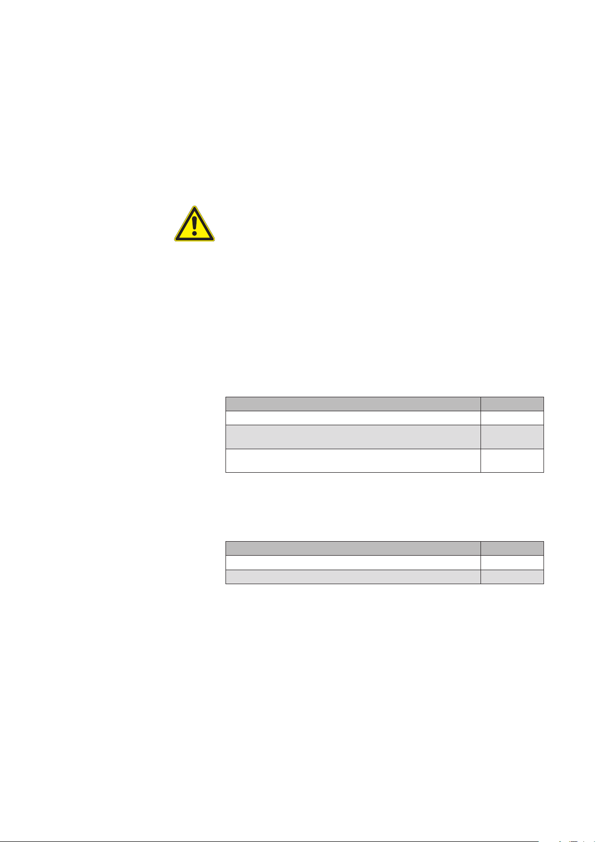
Apart from setting numeric values, a selection of presettings as well as the
following operating elements can also be shown at the right side:
In the first line you will see a bar graph at the right. The current value and the
units are shown above the bar; the extreme values that can be set are shown
at the left and right of the bar graph. By turning the touch wheel, the bar
moves to the right or left; the value changes accordingly.
You will see a box in each of the two lines below. This value is deactivated if
it is empty. By selecting the line and turning the touch wheel, a checkmark
can be set in the bottom row of the illustration; this value is then activated.
Tilting products (External Venetian Blinds and Louvre Blinds)
The movement behaviour of these tilting or slat products when controlled
manually (on site or centrally via control panel) is as follows:
A brief push of the button (shorter than approx. 0.6 seconds) triggers a tilting
impulse of the slats.
A longer push of the button (longer than approx. 0.6 seconds) triggers a
movement.
890557_d•en•01.07.2014 We reserve the right to carry out improvements
15
Introduction
3.2.1 Display of the products
Wisotronic 1-channel
Operating instructions
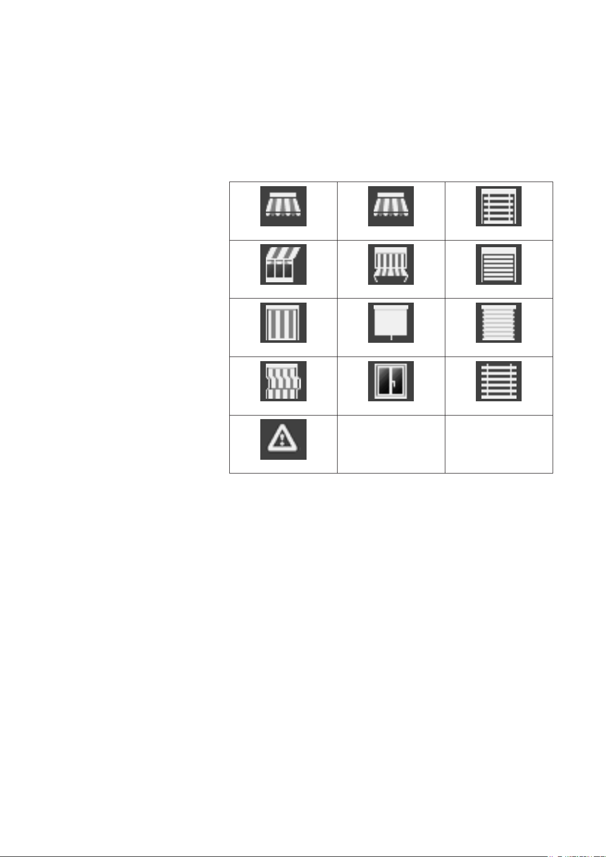
The various product types you control with the Wisotronic are assigned to
the channel during installation. When you select a channel in the main menu
by pressing the touch wheel, the operating menu appears. In the operating
menu the channel type is displayed graphically as follows:
Articulated arm awning Drop-arm awning External venetian blind
Conservatory awning Markisolette Roller shutters
Vertical awning Inside roller blind Pleated blind
Facade awning Window Venetian blind
Fault alarm contact
Fig. 2
We reserve the right to carry out improvements
16
890557_d•en•01.07.2014
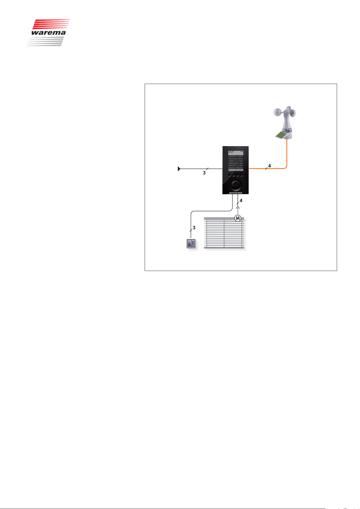
3.3 Principal structure of a
Wisotronic system
Introduction
Weather station
multisense
Wisotronic 1-channel
230 V / 50 Hz
pushbutton
Fig. 3 Overview of the structure of a Wisotronic system
The Wisotronic is a complete solution for controlling your sun shading product.
Whatever the season, Wisotronic will lower your energy consumption and
provide for a pleasant climate. The multisense weather station delivers all information necessary to respond properly to the weather to the Wisotronic.
To make it possible for you to operate the sun shading product in the conventional manner, Wisotronic makes additional inputs available for connecting a conventional sunblind push button.
Sun shading systemSunblind
890557_d•en•01.07.2014 We reserve the right to carry out improvements
17
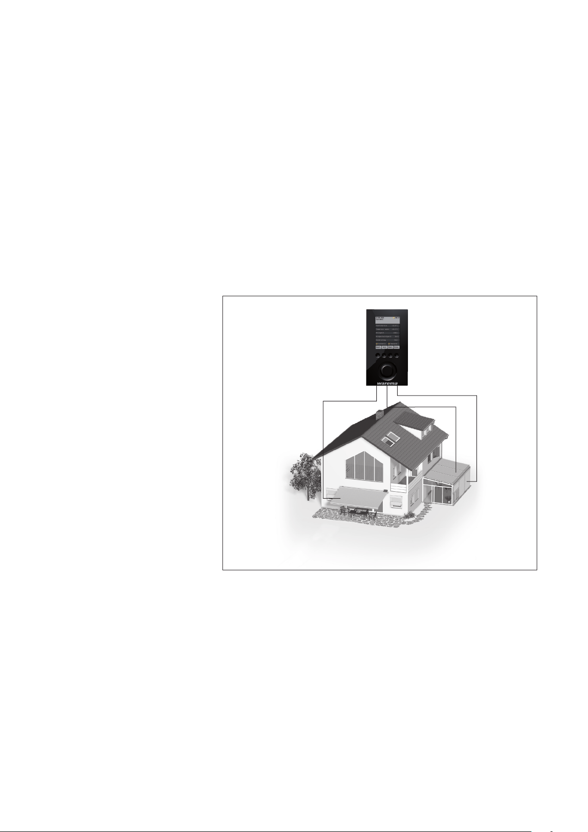
Introduction
3.4 Concept
3.4.1 Channels, facades and
products
NOTE To actuate multiple products through a single channel of the Wisotronic,
Wisotronic 1-channel
Operating instructions
Before you install and start the Wisotronic, this chapter will explain the basic
concept of the system and familiarise you with the many options and the
complex projects it can be used to realise.
Because misunderstandings have already occurred regarding the term
"Facade" in the area of sun shading control systems, this point shall be explained here in more detail:
The Wisotronic has 1, 2, 3 or 4 channels, depending on the model. Each
channel can access either a single product (e.g. an awning) or several products of the same type (e.g. roller shutters).
additional components may be required (such as motor control units).
➊
Fig. 4 Example: channels of the Wisotronic
Example In the example illustrated above, channel controls the awning on facade 1,
channel 2 the conservatory awning on facade 2 and channel 3 the external
venetian blinds of the conservatory on facade 2. This demonstrates that a
distinction according to building facades cannot be made in this example
since the individual channels are of importance here.
Example Another example: The Wisotronic controls all roller shutters on the west fa-
cade with channel 1, all roller shutters on the south facade with channel 2
and all roller shutters on the east facade with channel 3. Because the control
is divided here according to the facades, the term "facade" instead of "channel" could be used in this example.
➋
➌
We reserve the right to carry out improvements
18
890557_d•en•01.07.2014

Introduction
NOTE In these instructions we only use the term "Channel".
The Wisotronic always activates products through logic channels. The following product types can presently be activated using the Wisotronic:
Articulated arm awning Inside roller blind
Conservatory awning Vertical awning
External venetian blind Facade awning
Roller shutters Drop-arm awning
Pleated blind Markisolette
Venetian blind Fault alarm contact
Window
A product is connected directly to the outputs of a switch actuator of the
Wisotronic. It requires one or two switching outputs; for example, sun shading products require two switching outputs for raising and lowering.
3.4.2 Groups
3.4.3 Scenes
If you want to drive several channels together, they can be combined into a
group. You can then, for example, raise or lower the conservatory awning
and the external venetian blind of a conservatory together.
NOTE The group “inherits” the product properties of the first assigned channel; if
this is a roller shutter, for example, then the operating behaviour of the group
corresponds to that of a roller shutter even if other slat products or windows
belong to this group.
Of course, channels with identical products can also be combined to a
group. For example, if you have created a channel for the roller shutters
of each room, then all roller shutters of the building can be combined in a
group and moved together.
A maximum of 4 groups can be created.
NOTE This function is not available for Wisotronic 1-channel since is does not have
more than one channel.
A scenario (e.g. “roller shutter DOWN, articulated arm awning UP, window
CLOSED” when leaving the flat) can be stored (“learned”) in a scene and be
called at a later time.
For this, one or more channels are associated with the scene and the positions and states are set as desired. After the scene is stored, this scenario
can be recalled at any time by selecting the scene.
A maximum of 4 scenes can be created.
890557_d•en•01.07.2014 We reserve the right to carry out improvements
19

Introduction
3.4.4 Safety, comfort and basic
functions
Wisotronic 1-channel
Operating instructions
With the many different functions of the Wisotronic, a distinction is made between safety, comfort and basic functions:
Safety functions
Wind monitoring
Ice monitor
Comfort functions:
Sun control
Dawn/Dusk control
Temperature control
Diff. temp. control
Precipitation monitoring (this is a safety function which the operator can acti-
vate and deactivate)
Intermittent ventil.
Time switch
Cold protection
Manual operation
Hand-held transmitter allocation
Basic functions:
The key comfort functions with basic settings
Display of the safety functions
We reserve the right to carry out improvements
20
890557_d•en•01.07.2014
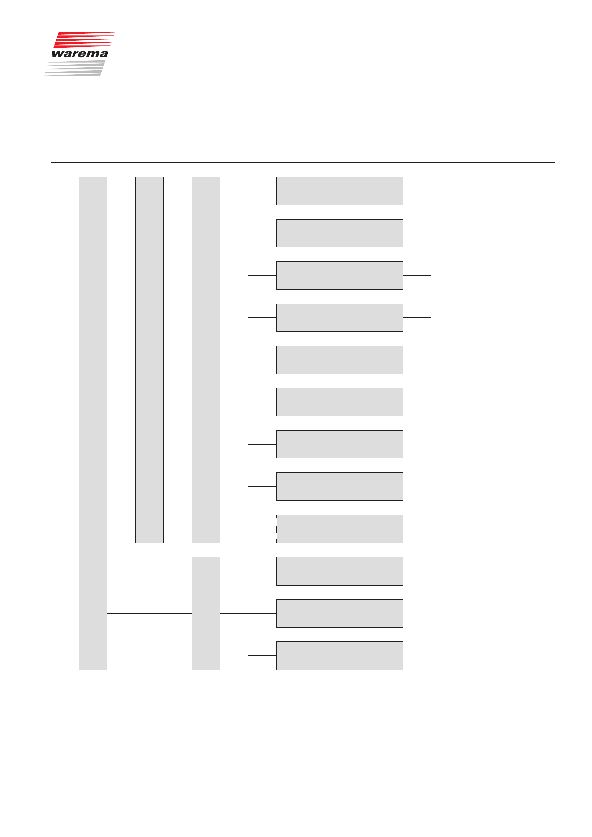
4 Menu structure
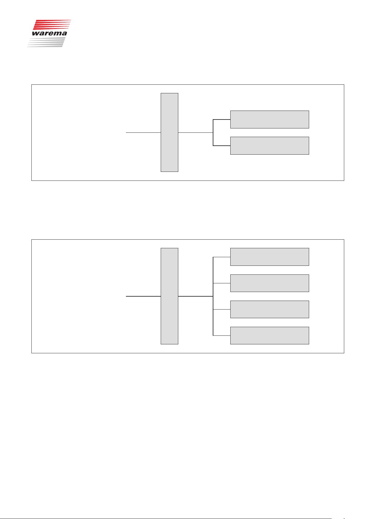
4.1 Main menus
Menu structure
Basic functions
Start menu
Main menu
Settings
Convenience functions
Safety functions
Manage channels, groups,
scenes
Leave time
System
Sensor allocation
Clean control panel
continue with
continue with
continue with
continue with
a
b
c
d
Service
All measured values
All triggers
Meas.val.
Faults
Fig. 5
Start menu level
890557_d•en•01.07.2014 We reserve the right to carry out improvements
21
Menu structure
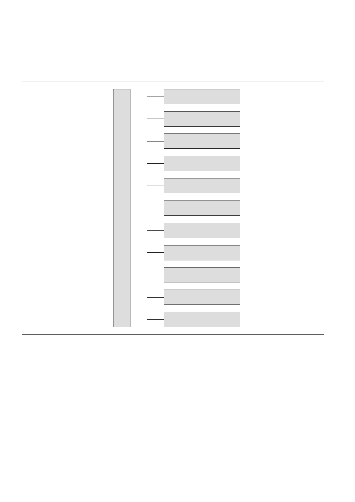
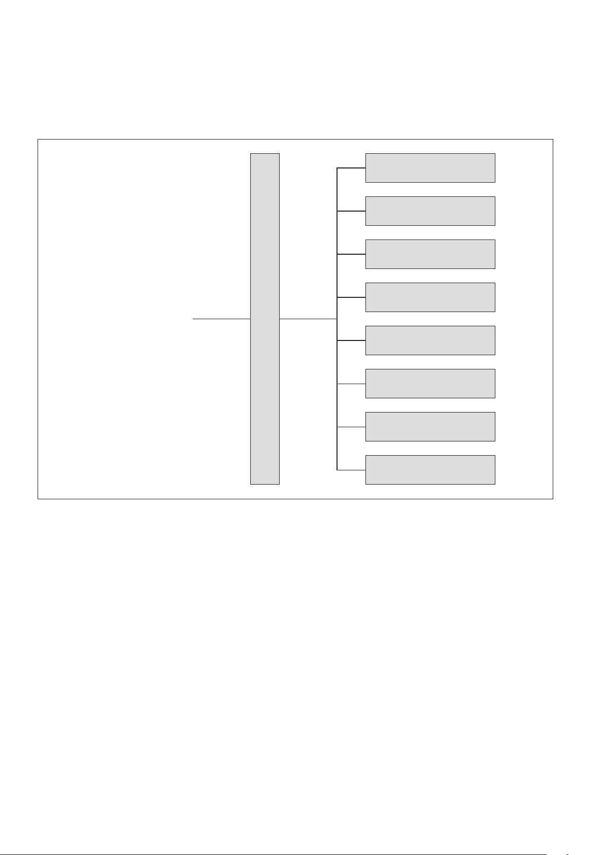
4.2 Convenience functions
Wisotronic 1-channel
Operating instructions
Sun control
Dawn/Dusk control
Temperature control
Precipitation monitor
Intermittent ventil.
from
a
Fig. 6
Comfort function menus
Convenience functions
Time switch
Cold protection
Leave
Absent
Manual operation
Hand-held transmitter allocation
We reserve the right to carry out improvements
22
890557_d•en•01.07.2014
4.3 Safety functions
from
b
Menu structure
Wind monitoring
Safety functions menus
Fig. 7
4.4 Manage channels,
groups, scenes
from
c
Safety functions
Ice monitor
Manage groups
Manage scenes
Sort channels, groups, scenes
Manage channels, groups, scenes
Fig. 8
Manage channels, groups, scenes menus
890557_d•en•01.07.2014 We reserve the right to carry out improvements
Change alias names
23
Menu structure
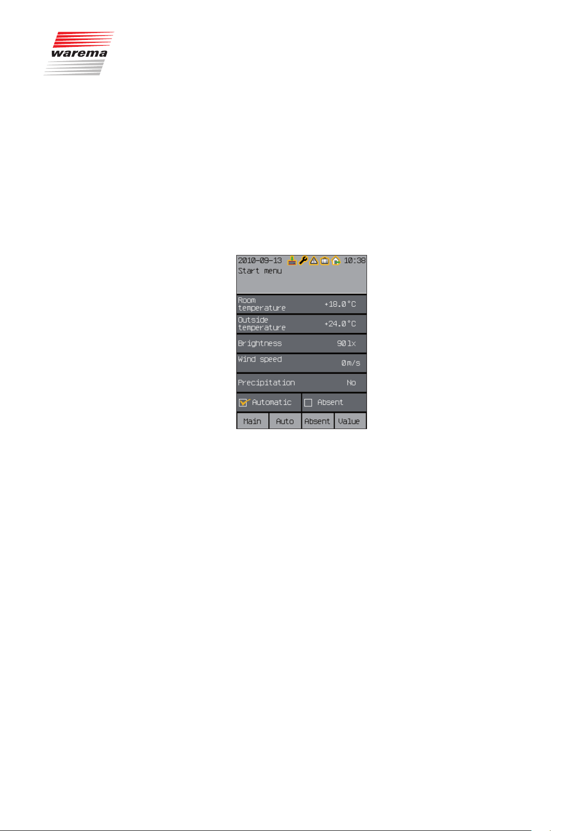
4.5 System
from
d
Wisotronic 1-channel
Operating instructions
Date / time
Display
Measured values start menu
Language
System
Sensor compensation
Fig. 9
System menus
Wind test
Restore settings
Software versions
We reserve the right to carry out improvements
24
890557_d•en•01.07.2014
5 Getting started
Getting started
First menu level
Second menu level
Third menu level
...
5.1 Start menu
In these instructions, miniature menu structures are presented at all important
locations (see the example here). They will help you navigate to the functions described there without having to leaf through an excessive number of
menus.
When the supply voltage of the Wisotronic has been switched on and you
have selected English as language, then you are automatically in the main
menu.
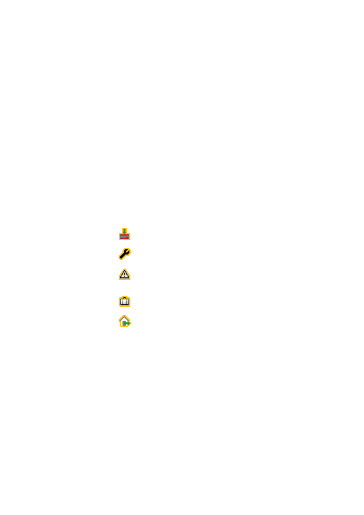
The following figure shows the Wisotronic start menu:
Fig. 10 Wisotronic start menu
The start menu elements:
A
Display of date and time
The header is fully visible in all menu levels.
B
Status display
These symbols are only displayed when a status is active.
C
Display of the menu name
D
Display of the current weather data
E
Indicator of whether the control functions are active
F
Indicator of whether "Absent" is active
G
Display of the button functions in the current menu
The footer is fully visible in all menu levels.
890557_d•en•01.07.2014 We reserve the right to carry out improvements
25
Getting started
Wisotronic 1-channel
Operating instructions
The header is visible in all menu levels. The date and time are shown at the
top (A). Various symbols are shown between the date and time, depending
on the state of the Wisotronic (B, Chapter 5.1.1 Status display). Below this,
the menu in which you are currently located (C) is identified.
The currently measured weather data of the sensors (D) appear in the
display field below this. In addition, you will see whether you have activated
the Automatic features (E) and whether the "Absent" switch has been
pushed on the control panel (F).
The footer (G) always shows which functions the four buttons below it currently have.
The following functions are assigned to the buttons in the start menu:
The [Main] function button leads to the main menu, where you can access
scenes, channels and groups. With the [Auto] button, you can switch the
automatic modes of the Wisotronic on and off. The [Absent] button is used
to activate the Absent function. The [Meas. val.] function button takes you
back to the start menu, where the measurement values, causes, malfunctions and histories are displayed. Histories are graphic presentations of the
chronological sequences of measured values that can be conveniently traced
with the cursor (see Chapter8.2 on page 100).
5.1.1 Status display
The symbols in the header indicate the following states of the Wisotronic:
Data must be loaded into the devices
Service mode
A fault occurred. Fault messages are displayed in the fault menu
([Start menu] > [Measured values] > [Faults]).
"Leave" function is activate
"Absent" function is active
We reserve the right to carry out improvements
26
890557_d•en•01.07.2014
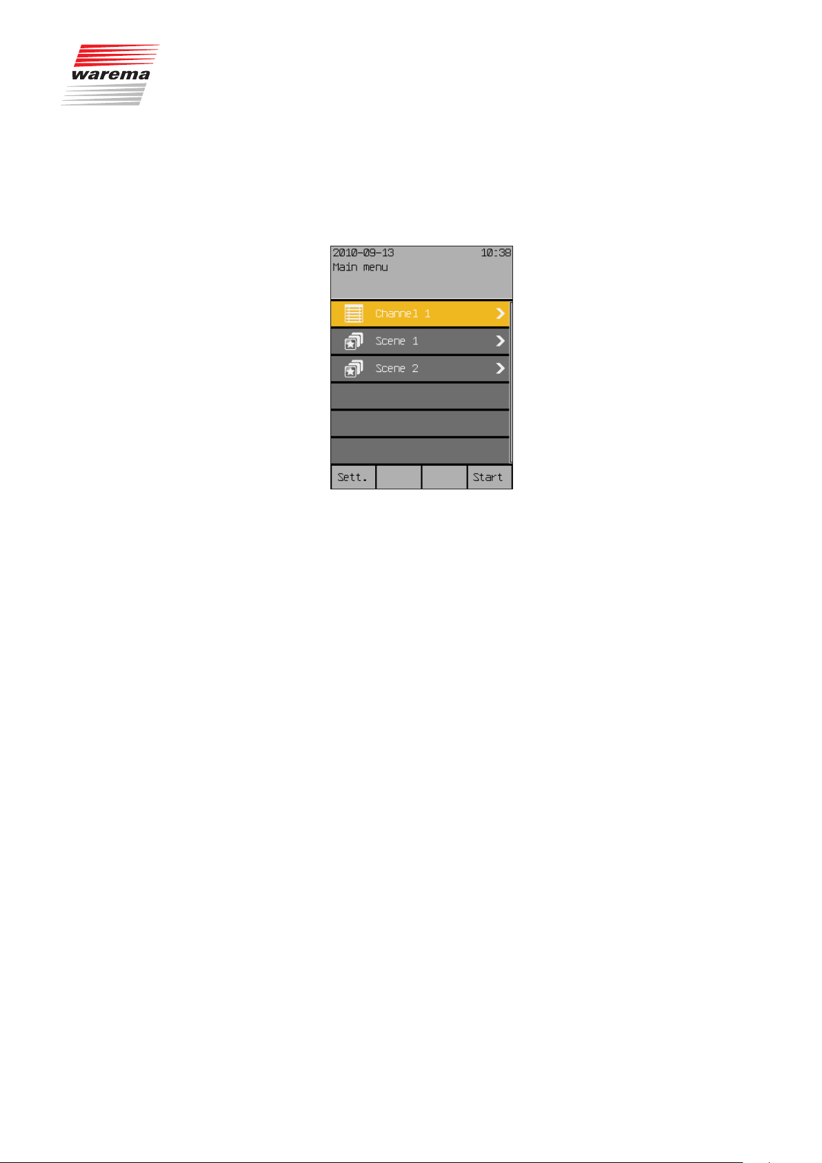
5.2 Main menu
Start menu
Main menu
Getting started
Pressing the [Main] function button in the start menu (all the way to the left)
takes you to the main menu. From most menus, you can return here with the
[Main] function button.
The typical display may look as follows:
In the centre you see the table of the menu lines (consisting of the channels,
groups and scenes created) which you can select with the touch wheel. A
clockwise rotation increment moves the coloured cursor line one line down, a
counterclockwise rotation increment moves the line one line up.
NOTE If the scroll bar on the right display edge has two colours, you can use the
touchwheel to scroll the table up or down.
The first line, for example, contains a so-called "scene", which you can
change.
The following functions are assigned to the buttons in the main menu:
The [Sett.] function button opens the settings menus and the [Start] function button takes you back to the start menu.
If the Wisotronic has been commissioned by one of our authorised dealers
and has been optimally adjusted to your sun shading products, no productspecific settings are required after switching on the supply voltage.
NOTE Please contact your specialist dealer if you want to make changes to the
safety functions.
890557_d•en•01.07.2014 We reserve the right to carry out improvements
27
Getting started
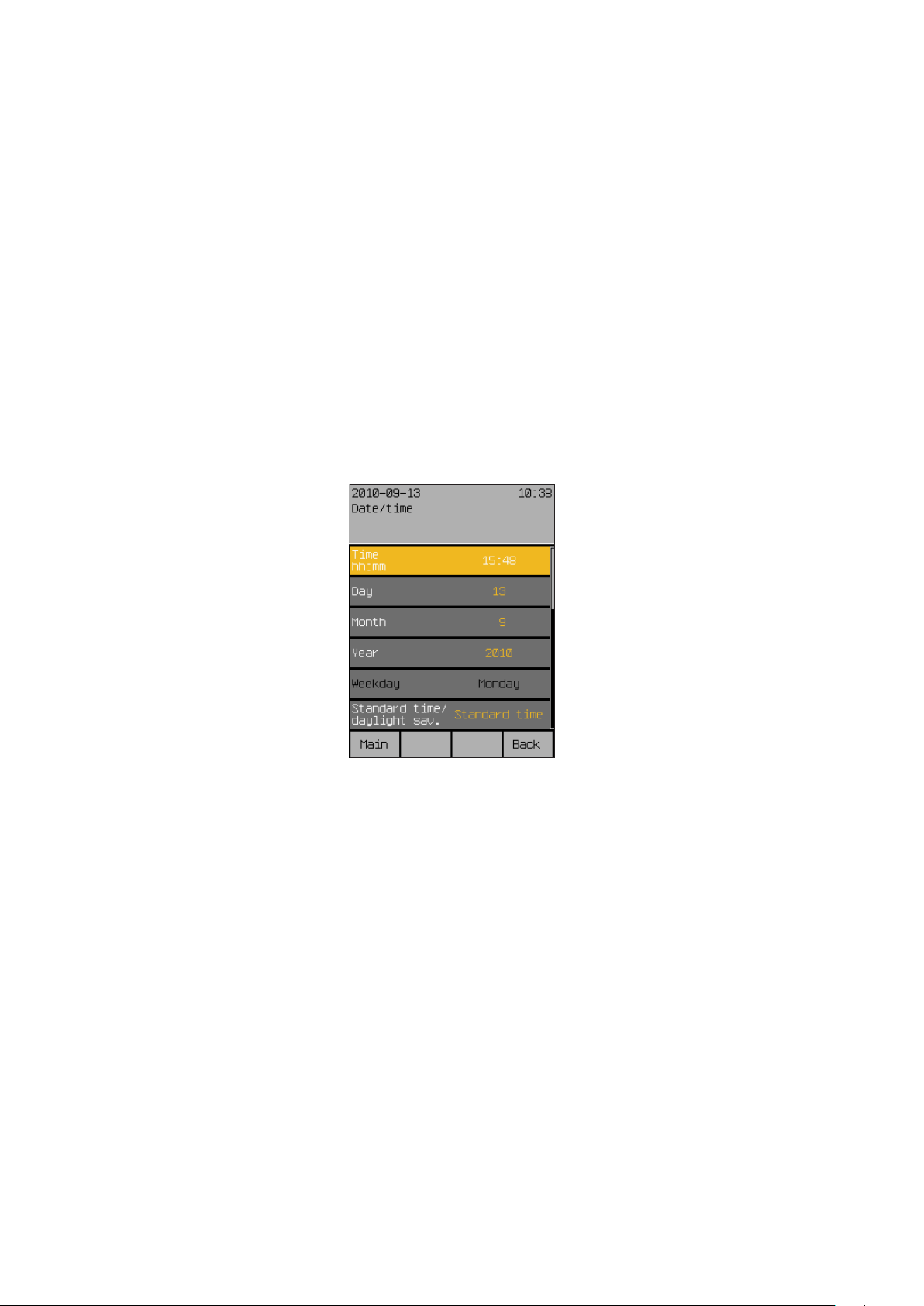
5.3 Example for operation:
Set time and date
Start menu
Main menu
Settings
System
Date/Time
Wisotronic 1-channel
Operating instructions
The example of setting date and time shall be used here to demonstrate how
the values of the Wisotronic can be set and changed with the touch wheel
and the function buttons (the following date and time displays are examples
and may differ from the display on your Wisotronic):
In the main menu, press the [Sett.] function button to get to the [Settings]
menu.
Turn the touch wheel clockwise until the selection cursor moves down to the
[System] line.
Press the touch wheel.
The upper line [Datum/time] of the [System] menu is highlighted in colour.
Press the touch wheel once more.
You will get to the menu [Date / time]:
The time set will be shown in the first line at the right.
Press the touch wheel.
The time (hours) changes colour. The value can now be set.
The hours are initially shown in a different colour, indicating that they can
now be set by turning the touch wheel. Pressing the touch wheel sets the
hours and switches to setting the minutes. After the minutes have been set,
pressing the touch wheel ends the input of the time; the new value is accepted and the coloured highlighting of the value disappears again.
Now select the [Day] line by turning the touch wheel and enter the day in the
same manner. Proceed in the same manner with month, year and weekday.
After you have activated the [Standard time/daylight sav.] menu line,
one rotation increment of the touch wheel to the left sets the standard time;
one rotation increment to the right sets the daylight saving time.
If you scroll the right table further down with the touch wheel, (a two-colour
scroll bar on the right edge of the display indicates that the menu has more
than six lines), the [Standard time/daylight auto] and [Use DCF77] lines
now become visible. They can be activated or deactivated by setting or
deleting the checkmark.
NOTE The DCF-77 time signal is only available if you are using a suitable sensor.
This function is not available at this time. Ensure that the "Use DCF77" function is deactivated.
We reserve the right to carry out improvements
28
890557_d•en•01.07.2014
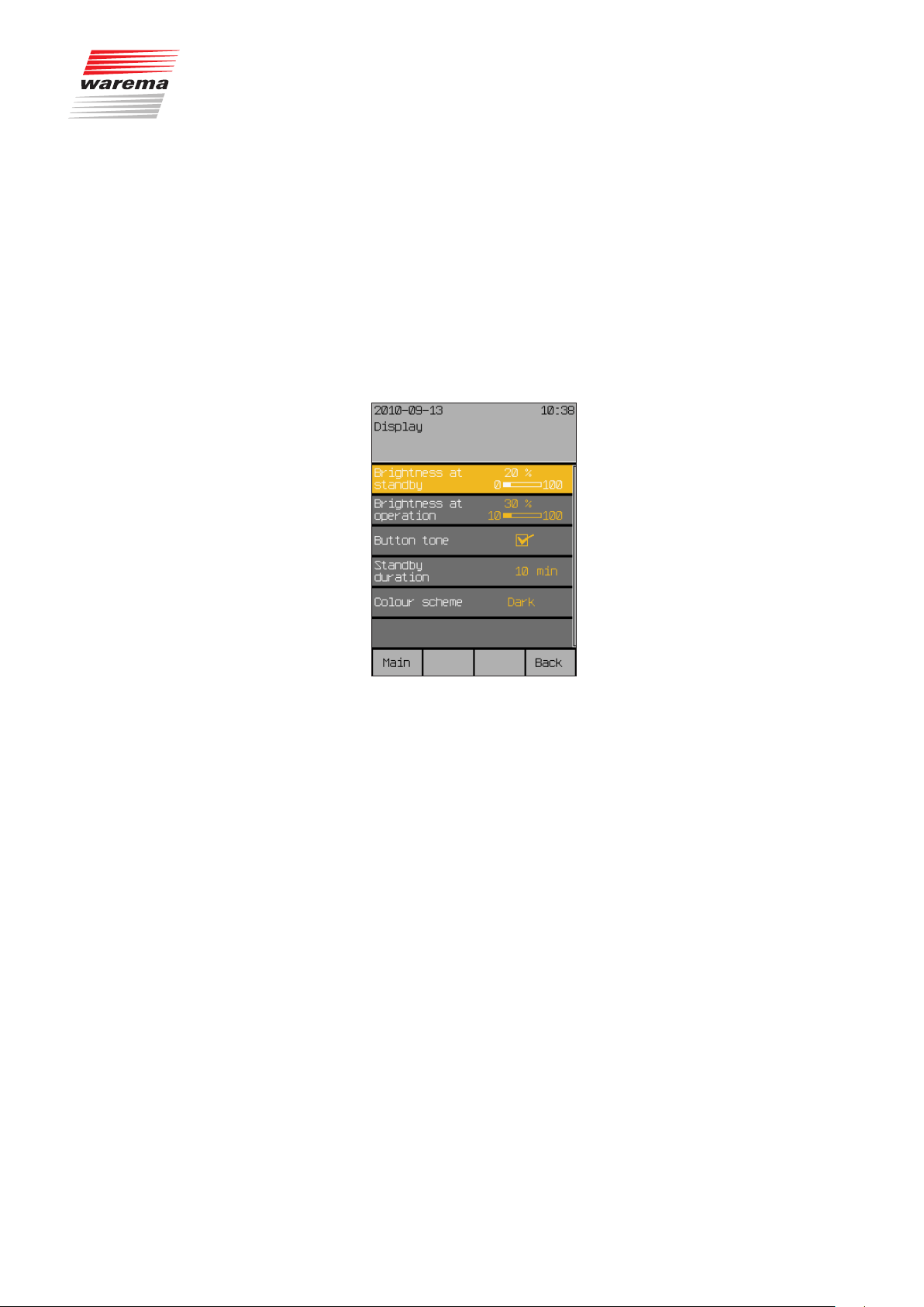
5.4 Example for operation:
Set display
Start menu
Main menu
Settings
System
Display
Getting started
The new settings for date and time have now been set.
By pressing the [Main menu] function button, you will return once more to
the main menu; the [Back] function button leads you to the [System] menu;
pressing [Back] once more leads you to the [Settings] menu.
Proceed as follows if you want to adjust the appearance of the display or
change the behaviour of the control elements:
Switch to the [Sett.] > [System] > [Display] menu:
The display is normally set by the factory for easy readability. However, you
can adjust it here to your personal needs and to the light incidence at the
installation location.
890557_d•en•01.07.2014 We reserve the right to carry out improvements
29

Getting started
Brightness at standby
Brightness at operation
Wisotronic 1-channel
Operating instructions
If the Wisotronic is not operated for longer than 3 minutes, the display is set
to a freely adjustable brightness value (e.g. darkened).
Set this [Brightness at standby] in the first menu line:
Press the touchwheel; the value on the right becomes editable and the dis-
play is dimmed to the indicated value.
By turning the touchwheel to the right or left, the bar moves and the bright-
ness is increased or reduced.
You will see the effects by the change of the display. If you select a setting
below 10% (OFF is displayed), the display will go completely dark after 3
minutes. The brightness is increased by turning the touchwheel in a clockwise direction.
The [Stand.] function button sets the factory setting of 20%.
Set the [Brightness at operation] in the same manner in the next menu
line.
The brightness during operation can be reduced to a minimum level of 10%.
Darkening the display completely during operation is counterproductive.
The factory setting ([Stand.] function button) is 30%.
Button tone
Additional functions
You change the behaviour of the function buttons in the line [Button tone].
Turning the touchwheel sets or deletes the checkmark at the right, thereby
activating or deactivating the actuation tone of the function buttons.
The [Stand.] function button sets the factory setting.
The other functions in this menu are described in detail in
Chapter 7.5.2 on page 87.
Pushing the function button [Back] returns you to the menu [System].
We reserve the right to carry out improvements
30
890557_d•en•01.07.2014

6 Manual operation
Start menu
Main menu
"Channel name"
Manual operation
Operating
Products connected to the Wisotronic can be operated directly via optional
external push buttons (if connected) or on the Wisotronic control panel.
NOTE If a safety function is active (e.g. wind alarm or ice alarm), Wisotronic locks
manual operation so that the sun shading product cannot be damaged.
This is how to operate a product on the Wisotronic control panel:
(The following displays are examples and may differ from the display on your
Wisotronic):
Press on the [Main] function button in the start menu.
The main menu is displayed. It shows all created channels and scenes
(scenes only appear if they were first created).
Turn the touchwheel clockwise until the selection cursor moves to the line
with the desired channel ([Channel 1] here).
Press the touch wheel.
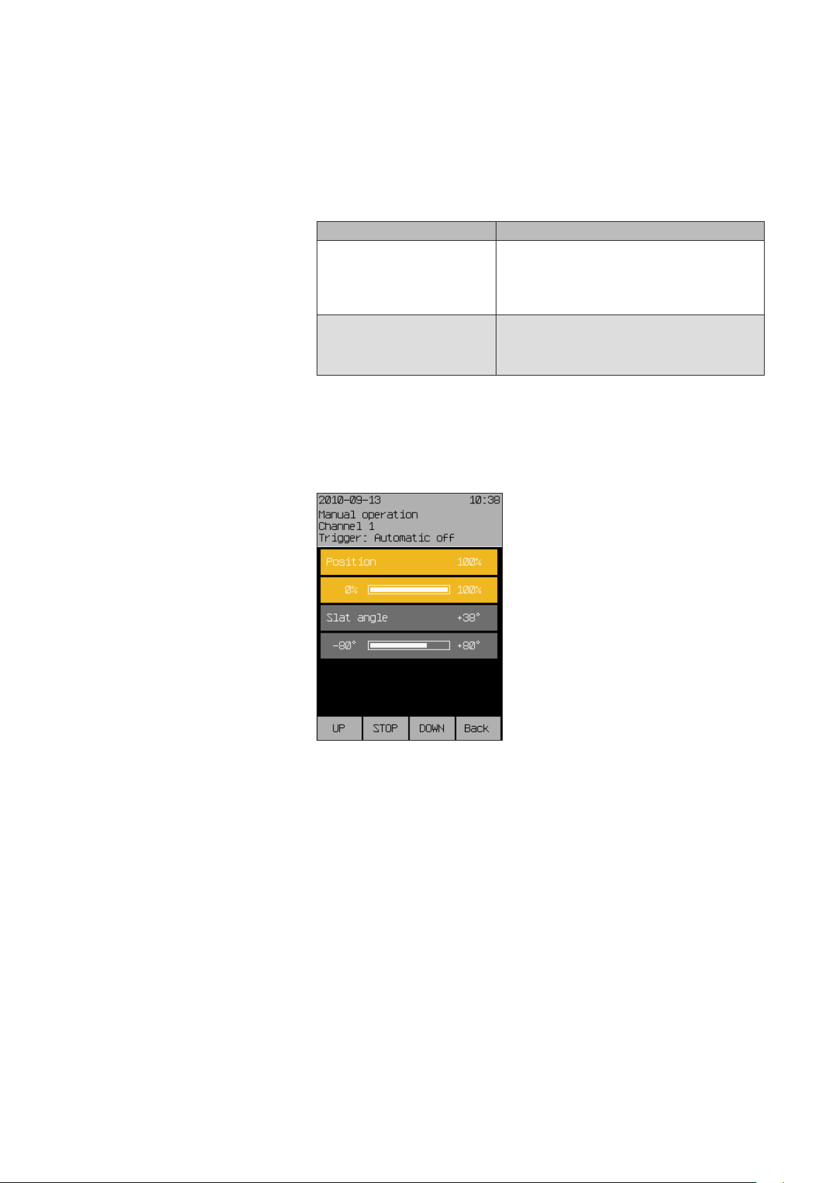
The [Manual Operation] menu opens:
890557_d•en•01.07.2014 We reserve the right to carry out improvements
31
Operating
Wisotronic 1-channel
Operating instructions
The push buttons and position parameters for the product type in question
(an external venetian blind in this case) are displayed.
Operate the product directly using the function buttons.
Product type Functionality
Slat products
such as external/internal venetian blinds
Other sun shading products
such as awnings or roller shutters
OR
Select a menu line with the touchwheel.
Press the touch wheel.
The bar display of this parameter changes colour.
UP short: The slats tilt up
UP long: The product moves up
STOP Product stops
DOWN short: The slats tilt down
DOWN long: The product moves down
UP The product moves up
STOP The product stops
DOWN Product moves down
We reserve the right to carry out improvements
32
Turn the touchwheel to select the right position and confirm the value by
pressing the wheel.
The blind automatically moves to the selected position.
890557_d•en•01.07.2014

7 Set functions
7.1 Basic functions
Start menu
Main menu
Settings
Basic functions
Basic functions
The basic functions are for new users and designed for quick operation. This
will allow you to perform the key settings on your Wisotronic. Once you are
more familiar with the control, you can make more specific settings in the
[Comfort functions] menu (see Chapter7.2 on page 37).
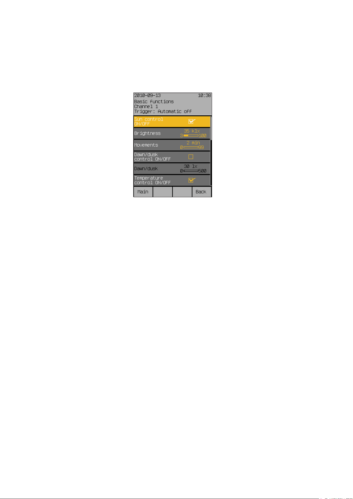
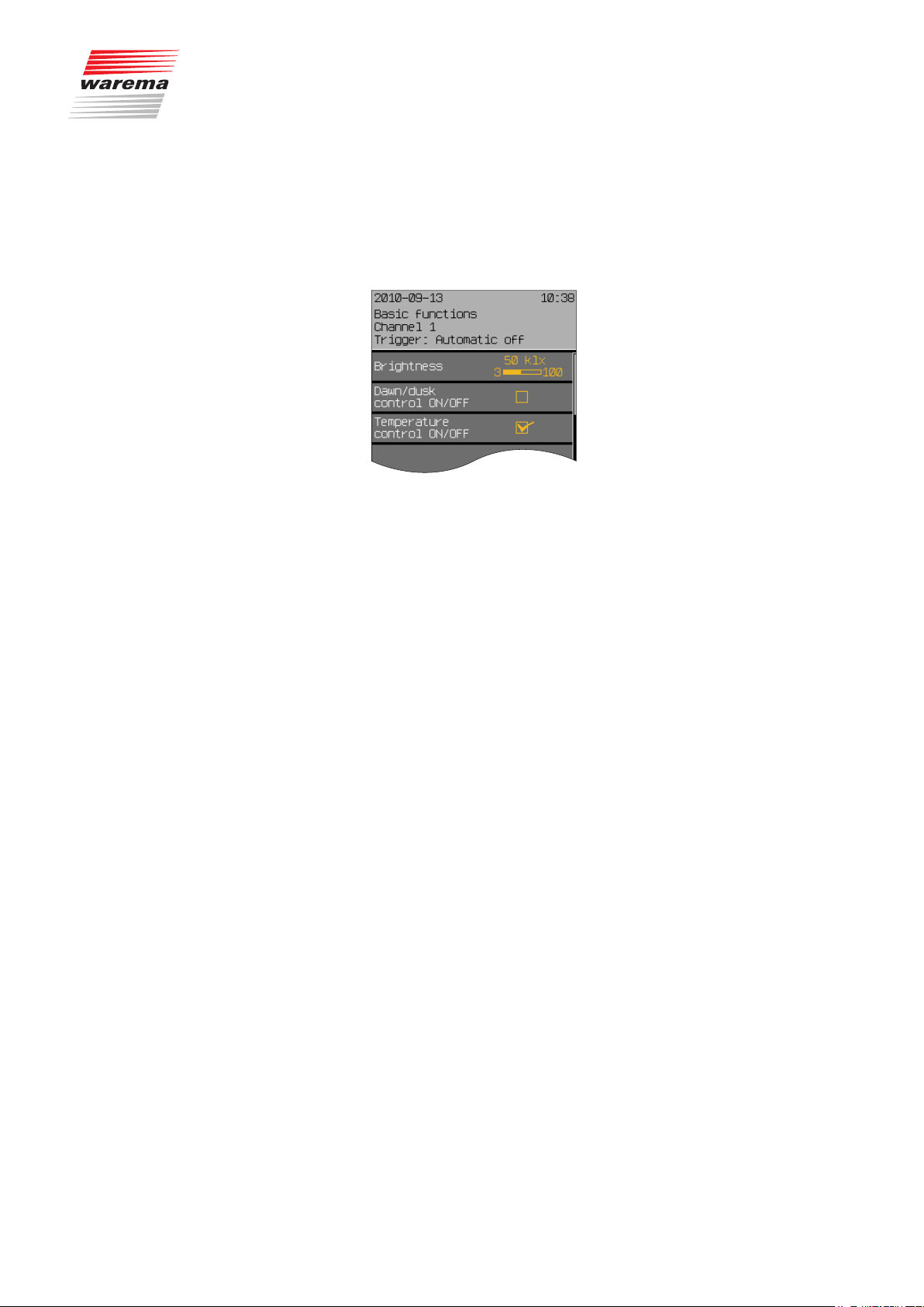
Press [Sett.] in the main menu and go to the [Basic functions] menu.
The following view appears in the display (the header may show the channel
name you selected instead of Channel 1 and the setting values may be different. An external venetian blind was chosen as product in this example.):
7.1.1 Sun control
ON/OFF
Set or delete the checkmark in the line [Sun control ON/OFF] to activate or
deactivate the automatic sun control.
The [Stand.] function button switches the sun control on or off, depending
on the channel type (factory setting).
890557_d•en•01.07.2014 We reserve the right to carry out improvements
33

Basic functions
7.1.2 Brightness
7.1.3 Movements
Wisotronic 1-channel
Operating instructions
The “Brightness” value specifies the brightness at which the sun shading
product is to be lowered by the sun control. The setting range is 3...100 klx.
Adjust the value for the brightness by turning the touchwheel (the bar at the
right moves accordingly).
The [Stand.] function button sets the value to the factory setting.
OTEN At the same time, the limit values SUN, CLEAR (e.g. moving to
a medium position or tilting up of the slats) and CLOUD (e.g.
raising the sun shading) are automatically adjusted.
A delay time can be assigned to the sun control to prevent the sun shading
product from being lowered immediately as soon as the brightness changes.
This quiets the motion behaviour of the sun shading product, thereby increasing the level of comfort. When the limit values are reached or exceeded for
the duration of this delay time, a command is triggered and the sun shading
product is lowered. The setting range is 0...99 minutes.
Adjust the value for the (delay) of the movements by turning the touchwheel
(the bar graphic at the right changes accordingly).
The value 0 min. deactivates the delay, the [Stand.] function button sets the
value to the factory setting.
OTEN At the same time, the delay times CLEAR (e.g. moving to a me-
dium position or tilting of the slats) and CLOUD (e.g. raising the
sun shading) are automatically adjusted.
7.1.4 Dawn/dusk control
ON/OFF
7.1.5 Dawn/dusk
Set or delete the checkmark in the [Dawn/dusk control ON/OFF] line to activate or deactivate the dawn/dusk control.
The [Stand.] function button switches the dawn/dusk control on or off, depending on the channel type.
OTEN The delay time for a move command is fixed for the dawn/dusk
control and cannot be changed. It is 5 minutes.
The “Dawn/dusk” value specifies at which brightness the sun shading product should be lowered or raised by the dawn/dusk control. The setting range
is 0...500 lx.
Set the “Dawn/dusk” value by turning the touchwheel.
The [Stand.] function button sets the value to the factory setting.
OTEN At the same time, the limit value for raising the sun hading
product is set to the same value.
We reserve the right to carry out improvements
34
890557_d•en•01.07.2014

7.1.6 Temperature control
ON/OFF
7.1.7 Temperature
7.1.8 Precipitation monitor
ON/OFF
Basic functions
To activate or deactivate the temperature control, set or delete the checkmark
in the [Temperature control ON/OFF] line.
The [Stand.] function button switches the temperature control on or off, depending on the channel type.
The "Temperature" value specifies at which temperature a sun shading product is lowered by the temperature control. The setting range is –10...+50°C.
To set the value for the temperature, turn the touchwheel to the desired posi-
tion.
The [Stand.] function button sets the value to the factory setting.
At the same time, the limit value for raising the sun shading is set 5 °C lower
to ensure flawless functioning of the automatic feature.
To activate or deactivate the precipitation monitor for the selected channel,
set or delete the checkmark in the [Precipitation monitor ON/OFF] line.
The [Stand.] function button sets the precipitation monitor to the standard
setting typical for the channel type.
7.1.9 Intermittent ventilation
CAUTION
The precipitation monitor is an adjustable safety function and was therefore
assigned to the comfort functions. If you have deactivated the function and
retract an awning wet from the rain, you must take care yourself to extend it
again in a timely manner to let it dry off during dry weather to prevent mould
from forming! An extended awning can also be damaged during rain by the
formation of water pockets!
Intermittent ventilation opens and closes motor-operated windows at adjustable intervals. This ensures sufficient fresh air supply in your rooms and prevents mould formation through excessive air humidity.
Set or delete the checkmark in the line [Intermittent ventilation] to acti-
vate or deactivate the intermittent ventilation mode.
The [Stand.] function button sets the channel-dependent factory setting.
890557_d•en•01.07.2014 We reserve the right to carry out improvements
35

Basic functions
7.1.10 Time switch
7.1.11 Wind monitoring
Wisotronic 1-channel
Operating instructions
The timer of the Wisotronic is equipped with 4 programmable switching times
per day and channel allowing you to automatically drive and switch the connected products.
Set or delete the checkmark in the [Time switch] line to activate or deacti-
vate the time switch.
The [Stand.] function button sets the channel-dependent factory setting.
NOTE Please contact your WAREMA dealer if you prefer a different setting of the
following safety functions.
This menu line shows you whether the “Wind monitoring” safety function is
activated for the selected channel (indicated by the checkmark set at the
left). The display is for information only and cannot be changed.
7.1.12 Ice monitor
This menu line shows you whether the “Ice monitoring” safety function is activated for the selected channel. The display is for information only and cannot
be changed.
We reserve the right to carry out improvements
36
890557_d•en•01.07.2014
7.2 Convenience functions
7.2.1 Sun control
Start menu
Main menu
Settings
Comfort functions
Sun control
Sun control
The comfort functions are used for the automatic control of your sun shading
product. Experienced users can adjust the control here to suit their particular
preferences.
CAUTION
Changing operator settings may impact the safety of the unit or reduce its
effectiveness. Please consult a specialist if you are not sure about the effects
of a modification.
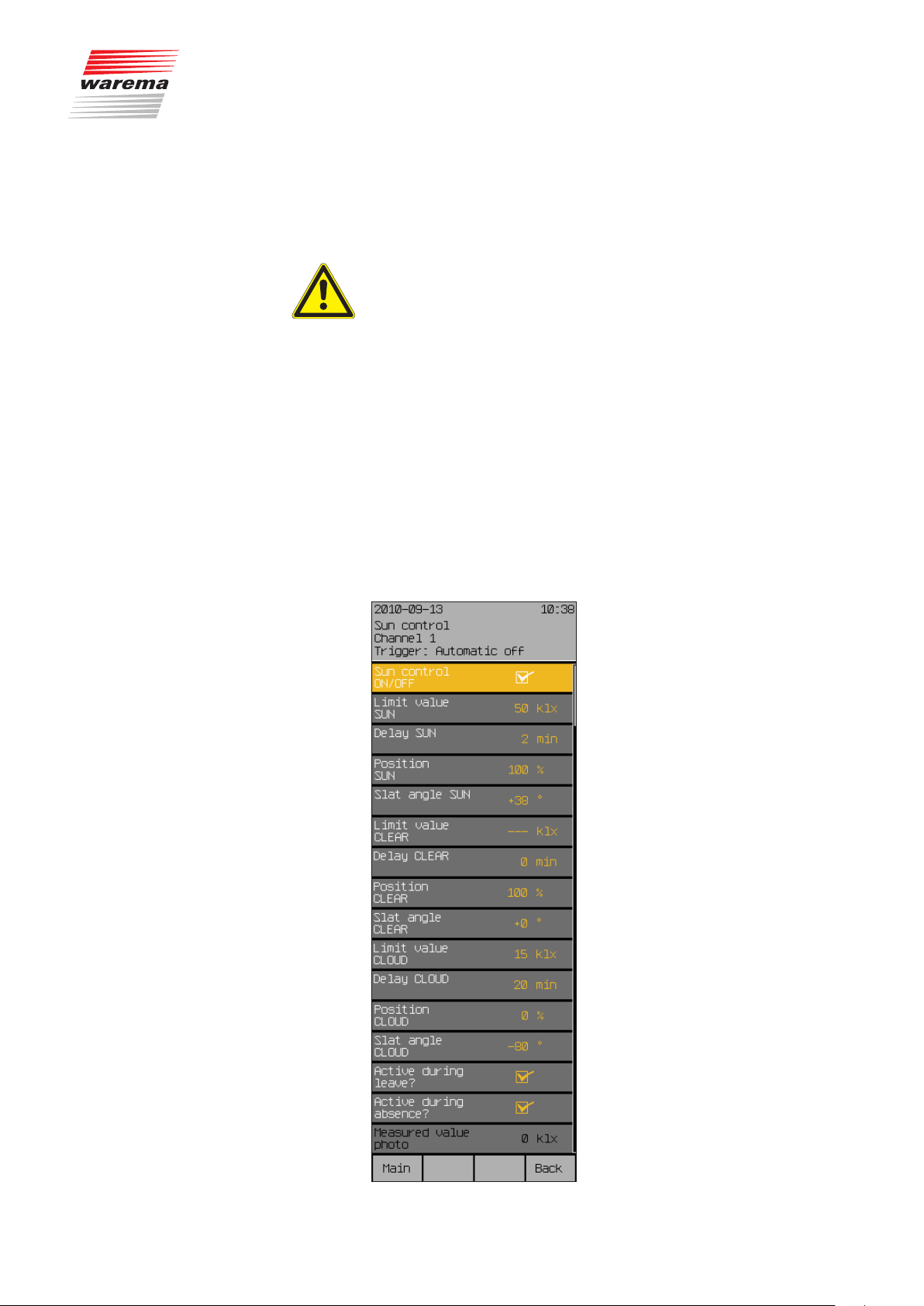
The sun control is one of the chief comfort functions of the Wisotronic, as
controlling the sun shading products on the basis of brightness is a fundamental requirement. A weather station can be employed to measure brightness. When the measuring value “PHOTO” exceeds the set limit value “SUN”,
a move command is triggered and the sun shading products are lowered.
When the "PHOTO" measured value falls below the set "CLOUD" limit value,
the sun shading product is raised again.
Press the [Sett.] function button in the main menu and select the following
menu: [Comfort functions] > [Sun control ON/OFF]
The following view appears in the display (the header may show the channel
name you selected instead of Channel 1 and the setting values may be different):
890557_d•en•01.07.2014 We reserve the right to carry out improvements
37

Sun control
7.2.1.1 Sun control ON/OFF
7.2.1.2 Limit value SUN
7.2.1.3 Delay SUN
Wisotronic 1-channel
Operating instructions
Set or delete the checkmark in the [Sun control ON/OFF] line to activate or
deactivate the sun control.
The [Stand.] function button sets the channel-dependent factory setting.
The value "SUN" specifies from which brightness the sun shading product of
this channel shall be lowered. The setting range is 3...100 klx.
Turn the touchwheel to set the "SUN" limit value.
To prevent the sun shading product from being immediately lowered at each
brightness change (e.g. when the sun temporarily shines through an otherwise thick cloud cover), a delay time can be assigned to the "SUN" limit
value. This quiets the motion behaviour of the sun shading product, thereby
increasing the level of comfort.
When the limit values are reached or exceeded for the duration of this delay
time, a move command is triggered and the sun shading product is moved
to the set position and slat angle. The setting range is 0...99 minutes.
7.2.1.4 Position SUN
7.2.1.5 Slat angle SUN
Turn the touchwheel to set the value for the "SUN" delay.
A setting of “0 min.” deactivates the delay, the function button [Stand.] sets
the factory setting).
The "SUN" position value specifies the position to which a sun shading
product is to be lowered in case of sunshine. The setting range is 0-100%; a
value of 0% corresponds to the upper limit position and a value of 100% to
the lower limit position.
Turn the touchwheel to set the "SUN" limit value.
The function button [---] leaves the position unchanged; function button
[Stand.] sets the value to the factory setting.
This setting is required when you have chosen a slat product (external or
internal venetian blinds) for the channel type. If you have connected a slat
product (such as external venetian blinds), you can specify the position of the
slats after they are lowered. This is especially useful if you prefer a specific
setting. In addition, you do not have to tilt the slats up after the product
descended automatically. The sun control automatically tilts up the slats if
programmed accordingly.
The factory setting for the slat position with automatic operation is 38°.
We reserve the right to carry out improvements
38
890557_d•en•01.07.2014

Sun control
The following drawing is meant to explain the setting of the slat angle:
Positive value:
Negative value: Slats are tilted inward
Setting 0°: The slats remain in a horizontal position
Slats are tilted outward
Outside Inside
7.2.1.6 Limit value CLEAR
+80
Fig. 11 Slat angle for external and internal venetian blinds
The setting range in ° depends on the first product set for this channel.
Turn the touchwheel to set the "SUN" limit value.
The [Stand.] function button sets the value to the factory setting.
This limit value specifies the brightness at which a sun shading product is to
move to a medium position and, in the case of external or internal venetian
blinds, the slats are to be tilted up, for example, to allow more light to enter
the room during a covered but otherwise bright sky. The setting range is
2...100 klx.
NOTE The limit value "CLEAR" is only assessed when the sun shading product was
first lowered automatically via "SUN" and not if the previous condition was
"CLOUD"!
Turn the touchwheel to set the "CLEAR" limit value.
The [Stand.] function button sets the limit "CLEAR" to the factory setting).
The function wheel [---] deactivates the limit value.
0
-80
890557_d•en•01.07.2014 We reserve the right to carry out improvements
39

Sun control
7.2.1.7 Delay CLEAR
7.2.1.8 Position CLEAR
Wisotronic 1-channel
Operating instructions
To prevent a sun shading product from being lowered or the slats from being
tilted up immediately at each brightness change (e.g. when the cloud cover
temporarily increases), a delay time can be assigned to the “Clear” limit
value. This quiets the motion behaviour of the sun shading product, thereby
increasing the level of comfort. If the values reach or drop below the limit
values for the duration of this delay time, the sun shading product moves and
the slats are tilted up. The setting range is 0...99 minutes.
Turn the touchwheel to set the "CLEAR" limit value.
The [Stand.] function button sets the "CLEAR" delay to the factory setting.
OTEN Simply set the delay time to “0 min.” to deactivate the delay.
The “CLEAR” position value specifies the position to which the sun shading product is to move when the sky is clear. The setting range is 0-100%; a
value of 0% corresponds to the upper limit position and a value of 100% to
the lower limit position.
If you do not want to trigger any movement during a clear sky,
the function button [---] leaves the “Position CLEAR” unchanged.
Turn the touchwheel to set the limit value “Position CLEAR”.
The function button [Stand.] sets the product-specific factory setting.
7.2.1.9 Slat angle CLEAR
7.2.1.10 Limit value CLOUD
This setting is required when you have chosen a slat product as channel
type (external or internal venetian blinds). If you have connected a slat product (such as an external venetian blind), you can specify how the slats are
to be set after the movement to the “CLEAR” position has been completed.
This is especially useful if you prefer a specific setting. In addition, you
do not have to tilt the slats up after automatic movement. The sun control
automatically tilts up the slats if programmed accordingly. The factory setting for the slat position with automatic operation is +0° (= horizontal, see
Chapter 7.2.1.5 on page 38).
Turn the touchwheel to set the value “Slat angle CLEAR”.
The function button [---] leaves the slat angle unchanged, function button
[Stand.] sets the value for position “Clear” to 0° (factory setting).
The "CLOUD" limit value specifies the brightness at which the sun shading
products of a channel is to be raised. The setting range is 1-100 klx.
To set the limit value “CLOUD”, turn the touchwheel (the value increases or
reduces depending on the direction of rotation).
The function button [---] deactivates assessment; the function button
[Stand.] sets the limit value “CLOUD” depending on the product (factory setting).
We reserve the right to carry out improvements
40
890557_d•en•01.07.2014

7.2.1.11 Delay CLOUD
7.2.1.12 Position CLOUD
Sun control
To prevent the sun shading product from being raised immediately at each
brightness change (e.g. when the sun is temporarily covered by a cloud), a
delay time can be assigned to the “CLOUD” limit value. This quiets the motion behaviour of the sun shading product, thereby increasing the level of
comfort. If the values reach or drop below the limit values for the duration of
this delay time, an “Up” command is triggered and the sun shading product
is raised. The setting range is 0...99 minutes.
Turn the touchwheel to set the value “Delay CLOUD”.
A setting of “0 Min.” deactivates the delay, the [Stand.] function button sets
the “Delay CLOUD” value to the factory setting.
The “CLOUD” position value specifies the position to which a sun shading
product is to be moved in case of sunshine. The setting range is 0-100%; a
value of 0% corresponds to the upper limit position and a value of 100% to
the lower limit position.
Turn the touchwheel to set the value “Position CLOUD”.
The [---] function button leaves the position unchanged; the [Stand.] function button sets the “CLOUD Position” value to the factory setting.
7.2.1.13 Slat angle CLOUD
7.2.1.14 Limit values of the sun
control
This setting is required when you have chosen a slat product as channel type
(external or internal venetian blinds). If you have connected a slat product
(such as an external venetian blind), you can specify how the slats are to be
set after the movement to the "CLOUD" position has been completed. This
is especially useful if you prefer a specific setting. In addition, you must no
longer tilt the slats manually after automatic movement. The sun control tilts
the slats automatically if programmed accordingly.
The factory setting for the slat position with automatic operation is -80°.
To set the “Slat angle CLOUD” value, turn the touchwheel (the value increas-
es or reduces depending on the direction of rotation).
The function button [---] leaves the slat angle unchanged; the function button [Stand.] sets the value for the “Slat angle CLOUD” to -80° (factory settings).
To ensure proper functioning of the automatic sun control in conjunction with
the limit value "CLEAR", the following comments must be observed when setting the limit values "SUN", "CLEAR" and "CLOUD":
NOTE The value for "CLOUD" must always be the smallest value, e.g. 5 klx. The
value for "SUN" must always be the greatest value, e.g. 30 klx. If used, the
value for "CLEAR" must be set in between, e. g. 10 klx.
To find the optimal setting for your sun shading product, you should test different values on a bright day with changing cloud cover. This is the only way
to achieve the optimal result.
890557_d•en•01.07.2014 We reserve the right to carry out improvements
41
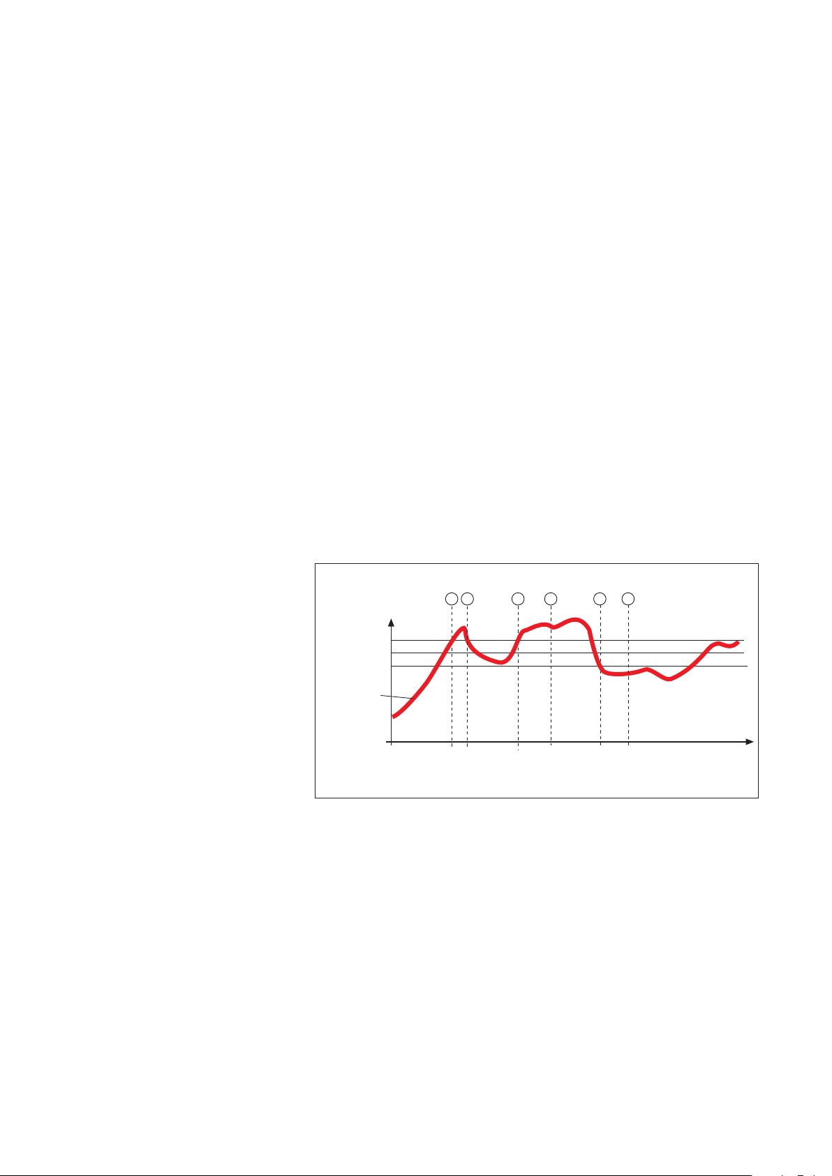
Sun control
7.2.1.15 Active during leave?
7.2.1.16 Active during absence?
7.2.1.17 Measured value photo
Wisotronic 1-channel
Operating instructions
Here you can activate or deactivate the sun control during your leave.
To change this setting, set or delete the checkmark in the line
[Active during leave?] by turning the touchwheel.
The [---] function button deletes the checkmark; the [Stand.] function button sets the factory setting.
Here you can activate or deactivate the sun control during your absence.
To change this setting, set or delete the checkmark in the line
[Active during absence?] by turning the touchwheel.
The [---] function button deletes the checkmark; the [Stand.] function button sets the factory setting.
The line “Measured value Photo” indicates the outdoor brightness currently
measured and is for information only.
7.2.1.18 Correct use of the sun
control
The setting values for the sun control described above are addressed below
in more detail. Using an example, the following graphic demonstrates schematically how the outdoor brightness can change in the course of a certain
time period:
1 2 3 4 5 6
Brightness in klx
Limit value SUN
Limit value CLEAR
Limit value CLOUD
Brightness curve
Delay SUN
< 2 Min
Fig. 12 Brightness curve and movement behaviour
Delay CLEAR
= 2 Min = 2 Min
Delay CLOUD
Time
The bold black curve represents the course of brightness; the three horizontal lines are the limit values you have set for raising or lowering the sun shading product. The vertical dashed lines mark the activation or deactivation
delay times. Assuming you have set 2 minutes for these
delay times, the following reaction of the sun shading will occur:
We reserve the right to carry out improvements
42
890557_d•en•01.07.2014

Sun control
The outdoor brightness increases until point a of the curve is reached; the
“SUN” limit value is reached at that point. Although the "SUN" delay now begins running, your sun shading product is not lowered yet. At point b of the
curve, the brightness drops below the “SUN” limit value once more before
the “SUN” delay time has elapsed. Your sun shading product stays up.
The brightness level increases later on and at point c exceeds the "SUN"
limit value again. Although the "SUN" delay now begins running, the sun
shading product is not lowered yet. The “SUN” delay time has elapsed at
Point d and the limit value is still exceeded - the sun shading product is now
lowered.
A cloud now moves in front of the sun and it gradually becomes too dark in
your rooms; the limit value “CLOUD” is undercut at Point d. Nothing happens initially because the “CLOUD” delay is started first - the sun shading
product is therefore not raised yet. The “UP” delay has finally elapsed at
Point d and the limit value “UP” is still undercut; the sun shading product is
now raised again.
Thus, when your delay times are set correctly, they enable the sun shading
product to be controlled in a manner that provides a high level of comfort.
They “quiet” the response of the control. As a consequence, the sun shading
product is not moved immediately whenever there is a change in the outdoor
brightness.
NOTE It also becomes apparent from the graphic that the limit value "SUN" must
always be set above the limit value "CLOUD" or the sun control will not work.
7.2.1.19 The sun control during a
wind, precipitation or ice
alarm
The sun control is not effective during a wind, precipitation or ice alarm. After
the alarm has been cancelled, the automatic sun control becomes active
again and resumes evaluating the brightness.
890557_d•en•01.07.2014 We reserve the right to carry out improvements
43

Dawn/Dusk control
7.2.2 Dawn/dusk control
Start menu
Main menu
Settings
Comfort functions
Dawn/dusk control
NOTE Dawn/dusk control and time switch: Please use the automatic control for
Wisotronic 1-channel
Operating instructions
The dawn/dusk control is another comfort function of the Wisotronic. It allows
control of the sun shading products as a function of the lighting conditions at
dawn or dusk, especially to ensure visual privacy. The “Dawn/dusk” sensor
of a weather station is used to register the brightness. When the measuring
value "Dawn/dusk" exceeds the set limit value "DAWN" for the duration of 5
minutes, a move command is triggered and the sun shading product moves
to the "DAWN" position. When the measuring value "Dawn/dusk" falls below
the set limit value "DUSK" for the duration of 5 minutes, the sun shading
product moves to the "DUSK" position.
these functions if you want to use other automatic features!
Press the [Sett.] function button in the main menu and switch to the
[Comfort functions] > [Dawn/dusk control] menu.
The following view appears in the display:
We reserve the right to carry out improvements
44
890557_d•en•01.07.2014

7.2.2.1 Dawn/dusk control ON/OFF
7.2.2.2 Limit value DAWN
7.2.2.3 Position DAWN
Dawn/Dusk control
In this menu line you set whether or not to activate the dawn/dusk control for
this channel.
Set or delete the checkmark in the [Dawn/dusk control ON/OFF] line to acti-
vate or deactivate the dawn/dusk control.
The function button [Stand.] selects the factory setting.
The "DAWN" value specifies the brightness at which a sun shading product is
to be moved in the morning. The setting range is 0...500 lx.
Turn the touchwheel to set the limit value "DAWN".
The function button [---] deactivates the evaluation; the function button
[Stand.] sets the limit value "DAWN" to the product-specific factory setting.
The "DAWN" position value specifies the position to which the sun shading
product is to move at dawn. The setting range is 0-100%; a value of 0% corresponds to the upper limit position and a value of 100% to the lower limit
position.
To set the value "Position DAWN", turn the touchwheel (the value increases
or reduces depending on the direction of rotation).
The function button [---] leaves the position unchanged; the function button
[Stand.] sets the value for the “Position DAWN” to the product-specific factory setting.
7.2.2.4 Slat angle DAWN
This setting is only useful when you have chosen a slat product (external or
internal venetian blinds). If you have connected a slat product (such as a
venetian blind), you can specify how the slats are to be set after lowering to
the "WARM" position is completed. This is especially useful if you prefer a
specific setting. In addition, you do not have to tilt the slats up after automatic
movement. The automatic dawn/dusk mode tilts the slats automatically if programmed accordingly.
Turn the touchwheel to set the value "Slat angle DAWN".
The function button [---] leaves the slat angle unchanged; the function button [Stand.] sets the value for the “Slat angle DAWN” to the product-specific
factory setting.
890557_d•en•01.07.2014 We reserve the right to carry out improvements
45

Dawn/Dusk control
7.2.2.5 Auto control DAWN
NOTE If you select [unchanged] here, the release setting of the last switching time
7.2.2.6 Limit value DUSK
Wisotronic 1-channel
Operating instructions
All automatic comfort features except for the dawn/dusk control and the timer switch can be disabled and enabled at any time. For this purpose, select
[Disable] or [Enable] under "Auto control DAWN".
of the dawn/dusk control or the timer applies. If the automatic comfort features were disabled before, the move commands "Position DAWN" and "Slat
angle DAWN" (see above) are carried out (otherwise always!).
To set whether the automatic comfort features should be enabled, disabled
or left unchanged at the value "Auto control DAWN", turn the touchwheel
(the current setting is shown on the left in the menu line).
The function button [---] leaves the automatic release unchanged; function
button [Stand.] sets the product-specific factory setting.
The "DUSK" value specifies the brightness at which a sun shading product is
to be moved to the "DUSK" position. The setting range is 0...500 lx.
Turn the touchwheel to set the value “Slat angle DUSK”.
The function button [---] deactivates assessment; the function button
[Stand.] sets the limit value "DUSK" to the product-specific factory setting.
7.2.2.7 Position DUSK
7.2.2.8 Slat angle DUSK
The "Position DUSK" value specifies the position to which the sun shading
product is to move at dusk. The setting range is 0-100%; a value of 0% corresponds to the upper limit position and a value of 100% to the lower limit
position.
Turn the touchwheel to set the value "Position DUSK".
The function button [---] leaves the position unchanged; the function button
[Stand.] sets the value for the “Position DUSK” to the product-specific factory setting.
This setting is only useful if you have chosen a slat product (external or internal venetian blinds) as the channel type. If you have connected a slat product (such as a venetian blind), you can specify how the slats are to be set
after the movement to the "DUSK" position has been completed. This is especially useful if you prefer a specific setting. In addition, you must no longer
tilt the slats manually after automatic movement. The dawn/dusk control tilts
the slats automatically if programmed accordingly. The factory setting for the
slat position with automatic operation is +80°.
Turn the touchwheel to set the value “Slat angle DUSK”.
The function button [---] leaves the slat angle unchanged; the function button [Stand.] sets the value for the “Slat angle DUSK” to the product-specific
factory setting.
We reserve the right to carry out improvements
46
890557_d•en•01.07.2014

7.2.2.9 Auto control DUSK
7.2.2.10 Active during leave?
Dawn/Dusk control
All automatic comfort features except for the dawn/dusk control and the timer switch can be disabled and enabled at any time. For this purpose, select
[Disable] or [Enable] under "Auto control DUSK".
NOTE If you select [unchanged] here, the release setting of the last switching time
of the dawn/dusk control or the timer applies. If the automatic comfort features were disabled before, the "Position DUSK" and "Slat angle DUSK" move
commands (see above) are not carried out (otherwise always!).
To set whether the automatic comfort features should be enabled, disabled
or left unchanged at the value "Auto control DUSK", turn the touchwheel (the
current setting is displayed on the left in the menu line).
The [---] function button leaves the automatic features unchanged; the
[Stand.] function button sets the product-specific factory setting.
In this menu line, you can activate or switch off the dawn/dusk control during
your leave.
Set or delete the checkmark in the line [Active during leave?] to activate
or deactivate the dawn/dusk control during your leave.
The function button [---] deletes the checkmark, the function button
[Stand.] sets it (factory setting).
7.2.2.11 Active during absence?
7.2.2.12 Measured value dawn/dusk
7.2.2.13 Automatic status
7.2.2.14 Auto control status
In this menu line, you can activate or deactivate the dawn/dusk control during your absence.
Set or delete the checkmark in the line [Active during absence?] to acti-
vate or deactivate the dawn/dusk control during your absence.
The [Stand.] function button sets the factory setting.
The line "Measured value dawn/dusk" indicates the outdoor brightness currently measured and is for information only.
The "State control" line shows the current status of the control mode and is
for informational purposes only.
The "State auto control" line shows the current status of the automatic control
and is for informational purposes only.
890557_d•en•01.07.2014 We reserve the right to carry out improvements
47

Dawn/Dusk control
7.2.2.15 Using dawn/dusk control
correctly
Example Using an example, the following graphic demonstrates schematically how the
Wisotronic 1-channel
Operating instructions
The following example illustrates the effects of the setting values for the
dawn/dusk control described above.
outdoor brightness can change in the course of dawn/dusk:
1 2 3 4
Brightness in lx
Limit value EVENING
Limit value MORNING
Brightness curve
7.2.2.16 The dawn/dusk control
during a wind or ice alarm
Delay
Delay
MORNING
5 Min 5 Min
Fig. 13 Brightness curve and movement behaviour
EVENING
The bold black curve represents the brightness in the course of the day; the
three horizontal lines are the limit values you have set for raising or lowering
the sun shading product.
The brightness increases at dawn until Pointa of the curve is reached; the
limit value “DAWN” is reached there and then exceeded. The activation delay
of 5 minutes (this cannot be changed) now begins to run. At Pointb of the
curve this time has elapsed and the limit value is still exceeded – the sun
shading product now moves to the set position “DAWN”.
The brightness decreases at dusk until Pointc of the curve is reached; the
limit value “DUSK” is reached there and is then undercut. The deactivation
delay of 5 minutes (this cannot be changed) now begins to run. At Pointc
of the curve this time has elapsed and the limit value is still undercut – the
sun shading product now moves to the set position “DUSK”.
NOTE If the limit value “DAWN” is undercut again within the delay time, the sun
shading product does not move to the set position “DAWN” at Pointb of
the example. If the limit value “DUSK” is exceeded again within the delay
time, the sun shading product does not move to the set position “DUSK” at
Pointd of the example.
The dawn/dusk control is not effective during a wind, precipitation or ice
alarm. The dawn/dusk control continues after the alarm has been cleared.
Time
We reserve the right to carry out improvements
48
890557_d•en•01.07.2014
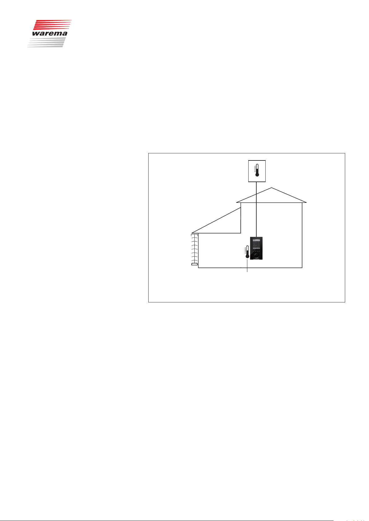
7.2.3 Temperature control
Temperature control
The automatic temperature mode of the Wisotronic permits, in conjunction
with temperature sensors (in the control unit, weather station), enables the
temperature-dependent control of your sun shading product. A sensor for the
room temperature is already integrated in the device itself (internal device
sensor). In addition, the Wisotronic can measure the "Outside temperature"
value via a weather station.
NOTE The temperature control can assess either the internal device sensor OR an
external sensor (weather station) but not several at the same time.
Example Sample application:
Weather station
Channel 1:
external
venetian
blind
In the Wisotronic:
temperature
measuring value
Fig. 14 Temperature control application example
The Wisotronic is installed in the living room.
Channel 1 controls the external venetian blind in the conservatory depending
on the temperature in the conservatory, measured internally in the Wisotronic
(the value "Temperature inside" from channel 1).
The outside temperature is measured with a weather station. The external
venetian blind is subject to ice monitoring and is raised in time before freezing.
890557_d•en•01.07.2014 We reserve the right to carry out improvements
49

Temperature control
7.2.3.1 Basic functions
The temperature control permits the comfortable control of your sun shading
depending on the inside and outside temperature.
The temperature control can be completely activated or deactivated per
channel.
The Wisotronic controls your unit by constantly comparing the temperature
limit values you have set with the local prevailing temperatures. Move commands are triggered when measured values exceed or fall below limit values.
Requirement: The necessary sensors must have been connected and assigned correctly.
Five operating modes are available for the temperature control:
The operating mode "Move directly" only triggers move commands when a
limit value is exceeded or fallen below.
The "Enable/disable sun" operating mode is also called "Temperature-
controlled sun control" and can be used to enable/disable the sun control (it
must have first been activated by setting the checkmark in the [Sun control]
menu).
The "Enable/disable differential temperature" operating mode controls win-
dow drives depending on the inside and outside temperature (cooling function) by activating the differential temperature control.
The operating mode "Direct control with steps" triggers move commands
when a limit value is exceeded or fallen below. According to adjustable step
times, additional move commands are triggered if limit values
continue to be exceeded or fallen below.
The operating mode "Difference temperature with steps" can control window
drives depending on the inside and outside temperature. According to adjustable step durations, additional move commands are triggered if limit values
continue to be exceeded.
Limit values must be specified to allow the Wisotronic to fulfil all these control tasks. The temperature control can thereby be optimally adjusted to your
preferences.
Wisotronic 1-channel
Operating instructions
We reserve the right to carry out improvements
50
890557_d•en•01.07.2014
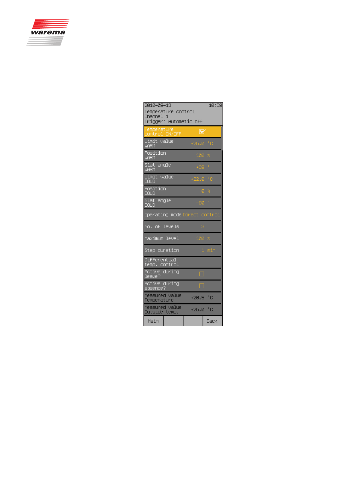
Temperature control
Start menu
Main menu
Settings
Comfort functions
Temperature control
To set the temperature control of your Wisotronic, press the function but-
ton [Sett.] in the main menu and switch to the [Comfort functions] > [Temperature control ON/OFF] menu.
The following view appears in the display:
7.2.3.2 Temperature control
ON/OFF
In this menu line, activate or deactivate the temperature control.
To activate or deactivate the temperature control, set or delete the checkmark
in the line [Temperature control].
The function button [Stand.] selects the factory setting.
890557_d•en•01.07.2014 We reserve the right to carry out improvements
51

Temperature control
7.2.3.3 Limit value WARM
The "WARM" limit value specifies the temperature at which a sun shading
product is to be lowered.
Example For example, you may want the inside temperature of your conservatory to
kept at a bearable level on hot summer days. Therefore, you can tell the
Wisotronic at which temperature value the sun shading product is to be lowered to give shade to the conservatory.
Turn the touchwheel to set the limit value "WARM".
The function button [---] deactivates the assessment; the function button
[Stand.] sets the factory setting.
7.2.3.4 Position WARM
The "Position WARM" value specifies the position to which a sun shading
product is to be moved. The setting range is 0-100%; a value of 0% corresponds to the upper limit position and a value of 100% to the lower limit
position.
Turn the touchwheel to set the value "Position WARM".
The function button [---] leaves the position unchanged; function button
[Stand.] sets the factory setting.
Wisotronic 1-channel
Operating instructions
7.2.3.5 Slat angle WARM
7.2.3.6 Limit value COLD
This setting is only useful when you have chosen a slat product (external or
internal venetian blinds). If you have connected a slat product (such as an
external venetian blind), you can specify how the slats are to be set after
lowering to the "WARM" position is completed. This is especially useful if you
prefer a specific setting. In addition, you do not have to tilt the slats up after
automatic movement. The temperature control tilts up the slats automatically
if programmed accordingly.
Turn the touchwheel to set the value "Slat angle WARM".
The function button [---] leaves the slat angle unchanged; function button
[Stand.] sets the factory setting.
The value “COLD” specifies at which temperature a sun shading product
shall be raised.
Example For example, you may want the sun to help heat your conservatory on cold
clear winter days. Therefore, you can tell the control at which temperature the
sun shading product is to be raised to allow sunlight into the conservatory.
The setting range is -10...+50 °C.
Turn the touchwheel to set the limit value “COLD”.
The function button [---] deactivates the assessment; the function button
[Stand.] sets the factory setting.
We reserve the right to carry out improvements
52
890557_d•en•01.07.2014

7.2.3.7 Position COLD
7.2.3.8 Slat angle COLD
Temperature control
The “Position COLD” value specifies the position at which the sun shading
product is to be raised. The setting range is 0-100%; a value of 0% corresponds to the upper limit position and a value of 100% to the lower limit position.
Turn the touchwheel to set the value "Position COLD".
The function button [---] leaves the position unchanged; function button
[Stand.] sets the factory setting.
This setting is only useful when you have chosen a slat product (external or
internal venetian blinds). If you have connected a slat product (such as an external venetian blind), you can specify how the slats are to be set after movement to the "COLD" position is completed. This is especially useful if you
prefer a specific setting. In addition, you must no longer tilt the slats manually
after automatic movement. The temperature control tilts the slats automatically if programmed accordingly.
Turn the touchwheel to set the value "Slat angle COLD".
The function button [---] leaves the slat angle unchanged; function button
[Stand.] sets the factory setting.
7.2.3.9 Operating mode, selecting
Direct control
Enable/disable sun
Example For example, on a cold clear winter day the sun should first heat up your
Five operating modes are available for the temperature control:
Direct control
Enable/disable sun
Enable/disable difference temperature
Direct control with steps
Difference temperature with steps
This operating mode simply triggers move commands only, when the limit
value is exceeded of fallen below.
This operating mode is called "Temperature-controlled sun control" and can
be used to enable/disable the sun control.
(It must first have been activated by setting the checkmark in the
[Sun control] menu).
conservatory before the sun shading product becomes active, after all, the
sun is the most economic source of heating. You can therefore program the
Wisotronic so that the automatic sun control is only released at a specific
inside or outside temperature. Here you will use the “Enable/disable sun” operating mode (=temperature-controlled sun control).
890557_d•en•01.07.2014 We reserve the right to carry out improvements
53

Temperature control
Enable/disable diff. temp.
In this operating mode, the control constantly compares the inside and outside temperature (see Section 7.2.3.13 for a description). Move commands
are triggered when limit values are exceeded or fallen below.
Example For example, you would like to maintain your preferred temperature in a liv-
ing area with attached conservatory. You connected a window drive to the
control for this purpose. You can now determine an area that represents your
"comfort temperature", e.g. 22–26 °C. When the sun shines into the conservatory in the morning, the room temperature also rises until it reaches your
max. value of 26 °C at some point. When the value is exceeded, the control
opens the window, allowing cool outside air into the room. When the outside
temperature also rises in the course of the day and is only 2 °C below the inside temperature, cooling only by venting is no longer possible. The window
is therefore automatically closed again. Only after the outside temperature
later falls by 5 °C below the inside temperature will the window be opened
again for cooling.The window closes again when the room temperature has
reached the minimum value of 22 °C.
Direct control with steps
This operating mode triggers move commands when the measured value
exceeds or falls below the limit value. Additional move commands are triggered according to adjustable step durations if measured values continue to
exceed or fall below limit values.
Example For example, you are controlling a conservatory awning with the temperature
control. You have specified 5 steps, a max. step of 100% (fully extended)
and a step duration of 5 minutes. When the max. temperature exceeds the
limit value "WARM", the awning is extended by one step (here 20%). After
the stage duration of 5 minutes, the awning is extended further to 40%, etc.
until the awning is either fully extended or the temperature once more drops
below the limit value "COLD". In this case, the awning is immediately moved
again to the "COLD" position.
Wisotronic 1-channel
Operating instructions
Diff. temp. with steps
7.2.3.10 Number of levels
In this operating mode the control constantly compares the inside and outside temperature. Move commands are triggered when limit values are exceeded or fallen below. In addition to the normal difference temperature control, additional move commands are triggered according to adjustable step
times, where the limit value is continuously exceeded or fallen below, e.g. a
window is opened farther incrementally.
This setting is required for the "Direct control with steps" and "Differential temperature with steps" operating modes. It specifies the number of stages used
to open the window. The value range is 1...6 steps.
Turn the touchwheel to set the value "Number of levels".
The function button [Stand.] sets the value “Number of levels” to the product-specific factory setting.
We reserve the right to carry out improvements
54
890557_d•en•01.07.2014

7.2.3.11 Maximum level
7.2.3.12 Step duration
Temperature control
This setting is required for the "Direct control with steps" and "Differential temperature with steps" operating modes. It specifies, for example, how far a window should be opened at the maximum stage. The value range is 0...100%.
Turn the touchwheel to set the value "Maximum level".
The function button [Stand.] sets the value “Maximum level” to the productspecific factory setting.
This setting is required for the "Direct control with steps" and "Differential
temperature with steps" operating modes. It specifies the period after which
switching to the next stage occurs. The value range is 1...100 minutes.
Turn the touchwheel to set the value “Step duration”.
The function button [Stand.] sets the value “Step duration” to the productspecific factory setting.
7.2.3.13 Difference temperature
control
These settings are needed for the operating modes "Enable/disable difference temperature" and "Difference temperature with steps" of the temperature control. You can use it to cool and ventilate a room, activating your window depending on the inside and outside temperature.
The difference temperature control works with four adjustable limit values:
Limit value "WARM" (Max. comfort temperature): It is too warm inside when
the inside temperature exceeds this value. The difference temperature control
is activated to vent and cool the room.
Limit value "COLD" (Min. comfort temperature): It is too cold inside when the
inside temperature falls below this value. The difference temperature control
is deactivated again and the window is closed.
“D-temp COOLER” limit value (cooler outside than inside): If the outside tem-
perature is lower than the inside temperature by at least the set difference
temperature, the window is opened for venting and cooling the room.
“D-temp WARMER” limit value (too hot outside): When the outside tem-
perature is below the inside temperature by no more than the set difference
temperature, the room can no longer be cooled by the warm outside air. The
window is closed again to prevent the room from being heated further by outside air that is becoming warmer.
890557_d•en•01.07.2014 We reserve the right to carry out improvements
55

Temperature control
Example The following example shall illustrate this function:
Wisotronic 1-channel
Operating instructions
Temperature
2
26 °C
22 °C
Diff. temp.
control
Window
Fig. 15 Difference temperature control
OFF OFFON
Close Close CloseOpen Open
1
3
4
Limit value WARM
Limit value COLD
Temp. inside
Temp. outside
Daily course
Set values: Limit value WARM: +26°C
Limit value COLD: +22°C
D-temp COOLER: 5°C
D-temp WARMER: 2°C
In the morning, it is initially too cool in the room. The sun shines through
windows into the room and warms it. When the inside temperature exceeds
the max. comfort temperature of 26 °C, the difference temperature control is
automatically activated a. The windows are opened because it is still cooler
outside than inside.
The room is cooled by venting it. In the course of the day, the outside temperature continues to rise because of the solar radiation. If it becomes too
hot outside to cool the room by venting (the current outside temperature lies
less than 2°C under the currently measured inside temperature b), the windows are closed again.
In the evening, the outside temperature drops again and at some point it
is cooler again outside than inside. When the currently measured outside
temperature lies at least 5°C below the inside temperature, the windows are
opened again for venting and cooling c).
When the min. comfort temperature of 22 °C has been reached in the
room, the windows are closed again to protect the room from becoming too
coold).
We reserve the right to carry out improvements
56
NOTE The correct setting of the limit values “D-temp COOLER” and “D-temp
WARMER” (limit value “D-temp COOLER” is clearly higher than limit value
“D-temp WARMER”) quiets the motion behaviour of the window drive and
as a consequence, the windows are not immediately opened and closed at
each temperature change.
890557_d•en•01.07.2014

Temperature control
Start menu
Main menu
Settings
Comfort functions
Difference temperature control
Temperature control
Limit value
D-temp COOLER
In the menu [Temperature control], select the menu line
[Diff. temp. control] with the touchwheel.
You will see the following submenu [Difference temperature control]
with all setting values:
The "D-temp COOLER" limit value specifies by how many degree the outside
temperature must be lower than the inside temperature for the window to
open.
If the difference between outside and inside temperature becomes greater
than this value, the window is opened.
Example Your max. comfort temperature is, for example, 26 °C and it has already
been reached. If the outside temperature is lower than the inside temperature
of the set difference temperature "D-temp COOLER", the window is opened
for venting and cooling. If you set 5 °C here, the window is only opened
again when the outside temperature 26 °C - 5 °C = 21 °C is fallen below.
The setting range is 0...25 °C.
Turn the touchwheel to set the limit value "D-temp COOLER".
The function button [---] sets the value to [---] (deactivated); the function
button [Stand.] sets the limit value "D-temp. COOLER" to 5 °C (factory setting).
890557_d•en•01.07.2014 We reserve the right to carry out improvements
57

Temperature control
Position D-temp COOLER
The “Position D-temp COOLER” value specifies the position or max. position
(for step settings) to which a window is to be moved. The setting range is
0...100%.
Turn the touchwheel to set the limit value “Position D-temp COOLER”.
The function button [---] leaves the position unchanged; the function button
[Stand.] sets the value for the “Position D-temp COOLER” to 100% (factory
settings).
Slat angle D-temp COOLER
This setting is only useful when you have chosen a slat product (external or
internal venetian blinds). If you have connected a slat product (such as an
external venetian blind), you can specify how the slats are to be set after
movement to the "D-temp COOLER" position is completed.
Turn the touchwheel to set the value "Slat angle D-temp COOLER".
The function button [---] leaves the slat angle unchanged; the function
button [Stand.] sets the value for the “Slat angle D-temp COOLER” to the
product-specific factory setting.
Wisotronic 1-channel
Operating instructions
Limit value
D-temp WARMER
The "D-temp WARMER" limit value specifies by how many degrees the outside temperature must be lower than the inside temperature for the window
to stay open. If the differential temperature falls below the "D-temp WARMER"
limit value, the window is closed.
Example Your max. comfort temperature is, for example, 26 °C and it has already
been reached. The window was already opened automatically. The outside
temperature rises and the difference temperature between outside and inside
sinks below the limit value "diff temp WARMER". The window is now closed.
Assuming you set 2 °C as "Limit value WARMER" and the rising outside temperature is only 2 °C or less below the inside temperature; the window will
be closed then. The setting range is 1...25 °C.
Turn the touchwheel to set the limit value "D-temp WARMER".
The function button [---] deactivates the evaluation of the limit value "D-temp
WARMER"; the function button [Stand.] sets the value to 2 °C (factory setting).
We reserve the right to carry out improvements
58
890557_d•en•01.07.2014

Position D-temp WARMER
Slat angle D-temp WARMER
Temperature control
The “Position D-temp WARMER” value specifies the position or max. position
(for step settings) to which a window is to be moved. The setting range is
0...100%.
Turn the touchwheel to set the limit value “Position D-temp WARMER”.
The function button [---] sets the value to [---] (position unchanged);
the function button [Stand.] sets the value “Position D-temp WARMER” to
0% (factory setting).
This setting is only useful when you have chosen a slat product (external or
internal venetian blinds). If you have connected a slat product (such as an
external venetian blind), you can specify how the slats are to be set after
movement to the "D-temp WARMER" position is completed.
Turn the touchwheel to set the value "Slat angle D-temp WARMER".
The function button [---] leaves the slat angle unchanged; the function
button [Stand.] sets the value for the “Slat angle D-temp WARMER” to the
product-specific factory setting.
Measured value
temperature
Measured value outside
temp.
The "Measured value temperature" line indicates the inside temperature currently measured at the control panel and is for information only.
The “Measured value outside temp.” line indicates the outside temperature
currently measured and is for information only.
Push the [Back] function button to return to the higher level menu of the tem-
perature control.
890557_d•en•01.07.2014 We reserve the right to carry out improvements
59

Temperature control
7.2.3.14 Active during leave?
Start menu
Main menu
Settings
Comfort functions
7.2.3.15 Active during absence?
7.2.3.16 Measured value
Temperature control
temperature
In this menu line, you can activate or deactivate the temperature control during your leave.
Set or delete the checkmark in the line [Active during leave?] to activate
or deactivate the temperature control during your leave.
The function button [Stand.] sets the product-specific factory setting.
Here you can enable or disable the temperature control during your absence.
To activate or deactivate the temperature control, set or delete the checkmark
in the line [Active during absence?].
The function button [Stand.] sets the product-specific factory setting.
The "Measured value temperature" line indicates the inside temperature currently measured at the control panel and is for information only.
Wisotronic 1-channel
Operating instructions
7.2.3.17 Measured value outside
temp.
The “Measured value outside temp.” line indicates the outside temperature
currently measured and is for information only.
We reserve the right to carry out improvements
60
890557_d•en•01.07.2014
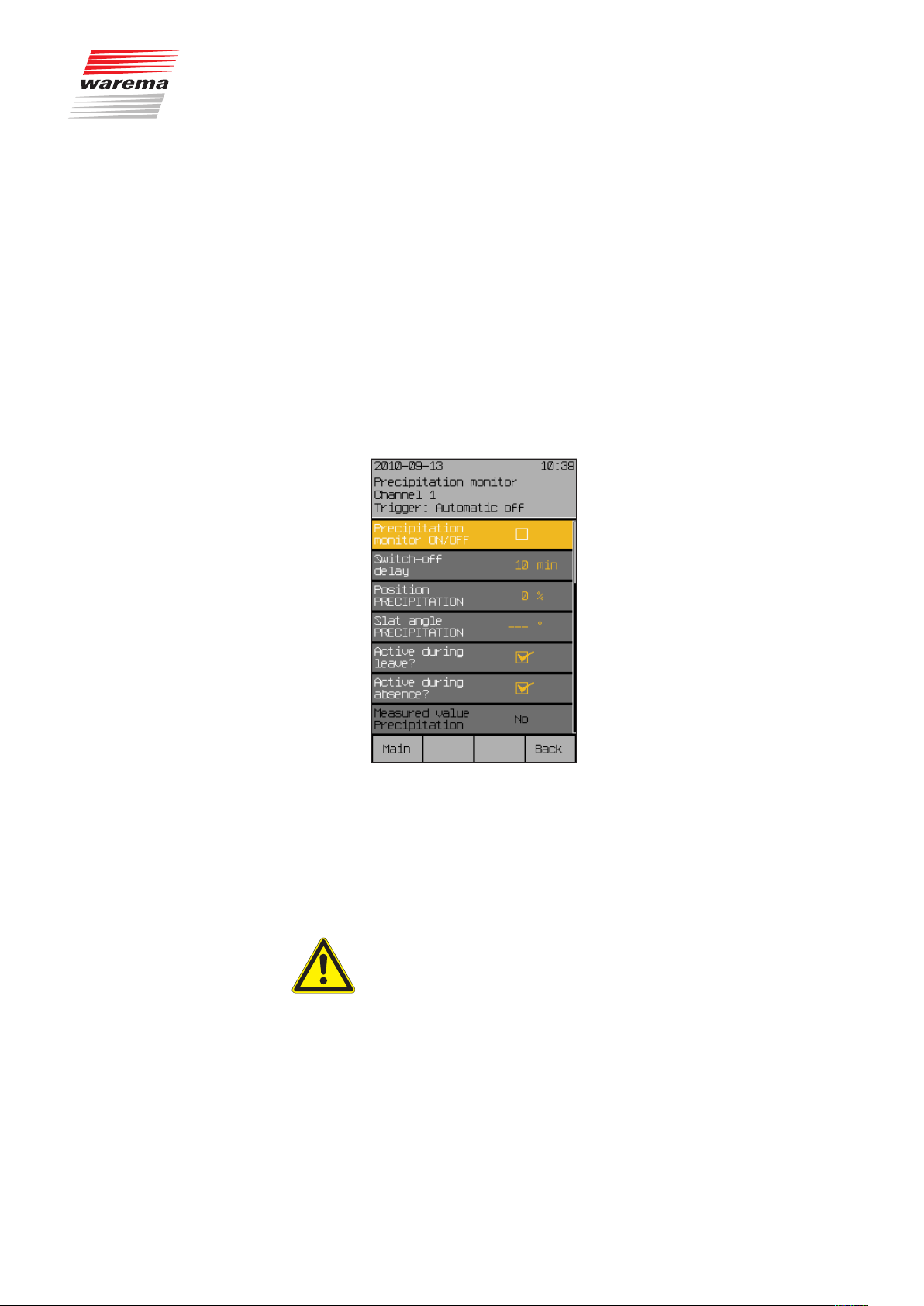
7.2.4 Precipitation monitor
Start menu
Main menu
Settings
Comfort functions
Precipitation monitor
Precipitation monitor
While external venetian blinds and roller shutters are relatively resistant to
precipitation, all fabric products such as articulated arm awnings and conservatory awnings must be protected against precipitation. If you have set
one of these fabric products in your Wisotronic as a channel, the precipitation monitor is automatically activated for these as a safety function. A weather station must be connected as a prerequisite for this safety function. When
precipitation (rain or snow) falls on the sensor surface of the weather station,
the product is raised. The selected comfort functions and manual operation
are locked. Once the weather station has dried again and the delay time set
in the control has elapsed, the comfort functions and the manual operation
are released again.
Press the function button [Sett.] in the main menu and go to the
[Comfort functions] > [Precipitation monitor] menu.
The following view appears in the display:
7.2.4.1 Precipitation monitor
ON/OFF
In this menu line, you can activate or deactivate the precipitation monitor for
the selected channel.
Set or delete the checkmark in the line [Precipitation monitor ON/OFF] to
activate or deactivate the precipitation monitor.
The function button [Stand.] sets the product-specific factory setting.
CAUTION
The precipitation monitor is an adjustable safety function and was therefore
assigned to the comfort functions. If you have deactivated the function,
for example, and retract an awning wet from the rain, you must take care
yourself to extend it again in a timely manner to let it dry off during dry
weather to prevent mould from forming on the fabric!
NOTE When the precipitation monitor detects precipitation, all comfort functions
and manual operation are disabled.
890557_d•en•01.07.2014 We reserve the right to carry out improvements
61

Precipitation monitor
7.2.4.2 Off delay
In this menu line, you can set the delay time after which the comfort functions
and the manual operation are released again after the end of the measured
precipitation. This delay time helps to "quiet" the motion behaviour of your
sun shading, thereby increasing the level of comfort. For example, move
commands are not executed every time rainfall stops briefly. The setting
range is 0-99 minutes.
Turn the touchwheel to set the value “Off delay”.
The value [0 Min.] deactivates the delay, the function button [Stand.] sets
the value for the product-specific factory setting.
7.2.4.3 Position PRECIPITATION
The “Position PRECIPITATION” value specifies the position to which the
sun shading product is to move during precipitation. The setting range is
0...100%; a value of 0% corresponds to the upper limit position and a value of
100% to the lower limit position.
Turn the touchwheel to set the value “Position precipitation”.
The [---] function button sets the value to [---] (Position unchanged); the
[Stand.]function button sets the “Position precipitation” value to the factory
setting.
Wisotronic 1-channel
Operating instructions
7.2.4.4 Slat angle PRECIPITATION
7.2.4.5 Active during leave?
This setting is only useful when you have chosen a slat product (external or
internal venetian blinds). If you have connected a slat product (such as an
external venetian blind), you can specify how the slats are to be set after
movement to the "PRECIPITATION" position is completed. This is especially
useful if you prefer a specific setting. In addition, you must no longer tilt the
slats manually after automatic movement. The precipitation monitor tilts the
slats automatically if programmed accordingly.
Turn the touchwheel to set the value “Slat angle PRECIPITATION”.
The function button [---] leaves the slat angle unchanged; function button
[Stand.] sets the product-specific factory setting.
In this menu line, you can activate or deactivate the precipitation monitor during your leave.
Set or delete the checkmark in the line [Active during leave?] to activate
or deactivate the precipitation monitor during your leave.
The [Stand.] function button sets the factory setting.
We reserve the right to carry out improvements
62
890557_d•en•01.07.2014

7.2.4.6 Active during absence?
7.2.4.7 Meas.value precipitation
Precipitation monitor
In this menu line, you can activate or deactivate the precipitation monitor during your absence.
Set or delete the checkmark in the line [Active during absence?] to acti-
vate or deactivate the precipitation monitor during your absence.
The [Stand.] function button sets the factory setting.
The menu line “Measured value precipitation” indicates, whether precipitation
is currently measured (a checkmark appears in the box at the left) and is for
information only.
890557_d•en•01.07.2014 We reserve the right to carry out improvements
63

Intermittent ventil.
7.2.5 Intermittent ventilation
Start menu
Main menu
Settings
Comfort functions
Intermittent ventilation
NOTE It is useful to also activate cold protection in addition to intermittent ventila-
Wisotronic 1-channel
Operating instructions
Intermittent ventilation is another comfort function of the Wisotronic that allows windows to be switched on a channel via a timer. It serves, on the one
hand, to prevent mould formation from humidity or condensation and, on the
other hand, to ensure a pleasant climate in your rooms and conservatories
through an adequate supply of fresh air.
tion (see Chapter 7.2.7 on page 71) to prevent excessive cooling down of
your conservatory/rooms.
In the main menu, press the function button [Sett.]. Now proceed to the
[Comfort functions] > [Intermittent ventilation] menu.
The following view appears in the display (the header may show the channel
name you selected instead of Channel1 and the setting values may be different):
7.2.5.1 Intermittent ventil. ON/OFF
7.2.5.2 Ventilation duration hh:mm
In this menu line, you can activate or deactivate intermittent ventilation.
Set or delete the checkmark in the line [Intermittent ventil. ON/OFF]
to activate or deactivate the intermittent ventilation.
The function button [Stand.] sets the product-specific factory setting.
In this menu line, you can set the duration in hours and minutes for which
ventilation should be performed by opening a window.
Turn the touchwheel to set the “Ventilation duration hh:mm” value. Pressing
on the wheel causes the display to jump to minutes. Set the minutes in the
same manner.
The function button [Stand.] selects the factory setting.
We reserve the right to carry out improvements
64
890557_d•en•01.07.2014

7.2.5.3 Break duration hh:mm
7.2.5.4 Ventilation step
7.2.5.5 Active during leave?
Intermittent ventil.
In this menu line, you can set the duration in hours and minutes for which
intermittent ventilation is interrupted.
Turn the touchwheel to set the “Break duration hh:mm” value. Pressing on
the wheel causes the display to jump to minutes. Set the minutes in the same
manner.
The function button [Stand.] sets the pause duration to the factory setting.
In this menu line, you can set the level of the intermittent ventilation in percent. The setting range is 0...100%.
Turn the touchwheel to set the value “Ventilation step”.
The function button [Stand.] sets the product-specific factory setting.
In this menu line, you can activate or deactivate intermittent ventilation during
your leave.
Set or delete the checkmark in the line [Active during leave?]
to activate or deactivate intermittent ventilation during your leave.
The function button [Stand.] sets the product-specific factory setting.
7.2.5.6 Active during absence?
In this menu line, you can activate or deactivate intermittent ventilation during
your absence.
Set or delete the checkmark in the line [Active during absence?]
to activate or deactivate intermittent ventilation during your absence.
The function button [Stand.] sets the product-specific factory setting.
890557_d•en•01.07.2014 We reserve the right to carry out improvements
65

Time switch
7.2.6 Time switch
Start menu
Main menu
Settings
Comfort functions
Time switch
Wisotronic 1-channel
Operating instructions
The time switch is another comfort function of the Wisotronic that allows the
sun shading product to be raised or lowered at a specific time. Move commands can be programmed
for each individual day of the week
for a complete work week together (Monday till Friday)
for the weekend (Saturday and Sunday)
for a complete week together (Monday till Sunday)
x. Four programmable switch times are available for each day. Furthermore,
the position and subsequent tilting of the slats of a slat product can be programmed with different slat angles.
NOTE Dawn/dusk control and timer: Please use the automatic control (see 7.2.6.5)
for these functions if you want to use other automatic features.
Press the function button [Sett.] in the main menu and go to the
[Comfort functions] > [Time switch] menu.
The following view appears in the display (the header may show the channel
name you selected instead of Channel1 and the setting values may be different):
We reserve the right to carry out improvements
66
890557_d•en•01.07.2014

7.2.6.1 Time switch ON/OFF
Time switch
In this menu line, you can activate or deactivate the timer switch for the selected channel.
Set or delete the checkmark in the line [Time switch ON/OFF] to activate or
deactivate the time switch.
The function button [Stand.] sets the product-specific factory setting.
Monday
Tuesday
Wednesday
Thursday
Friday
Saturday
Sunday
Monday - Friday
Saturday - Sunday
Monday - Sunday
Selecting this menu line leads you to the respective submenu where you can
set the switching times for the respective day or together for the selected
days. An example is provided here showing the settings for Monday; the submenus of the other days are identical.
Select the menu line [Monday] with the touchwheel and press the
touchwheel.
The following view appears in the display (the header may show the channel
name you selected instead of Channel 1 and the setting values may be different):
890557_d•en•01.07.2014 We reserve the right to carry out improvements
67

Time switch
7.2.6.2 ST1: switch time hh:mm
7.2.6.3 ST1: position
Wisotronic 1-channel
Operating instructions
If the sun shading product or another product are to move at the same time
every Monday, you can set this switch time here. The setting range is 00:00
h to 23:59 h. If you do not want to move/switch the product on Monday, you
can also deactivate the switching time [---].
Turn the touchwheel to set the hours of the “ST1: switch time hh:mm”. Press-
ing on the wheel causes the display to jump to minutes. Set the minutes in
the same manner.
The [---] function button leaves the switch time unchanged; the [Stand.]
function button sets the product-specific factory setting.
The "ST1: Position" value specifies the position to which the sun shading
product is to move at switch time 1. The setting range is 0-100%; a value of
0% corresponds to the upper limit position and a value of 100% to the lower
limit position.
Turn the touchwheel to set the value “ST1:Position”.
The function button [---] leaves the position unchanged; the function
button [Stand.] sets the value for the “ST1: Position” to factory setting.
7.2.6.4 ST1: Slat angle
7.2.6.5 ST1: Auto control
This setting is only useful when you have chosen a slat product (external or
internal venetian blinds). If you have connected a slat product (such as an
external venetian blind), you can specify how the slats are to be set after
movement to the "ST1" position is completed. This is especially useful if you
prefer a specific setting. In addition, you no longer need to tilt the slats manually after a time-controlled movement. The timer switch tilts the slats for you
if programmed accordingly. The factory setting for the slat position for timed
operation is -80° (see Chapter 7.2.1.5 on page 38).
Turn the touchwheel to set the value "ST1:Slat angle".
The function button [---] leaves the slat angle unchanged; the function button [Stand.] sets the value “ST1:Slat angle” to the factory setting.
All comfort functions except for the dawn/dusk control and the timer switch
can be disabled and enabled at switch time 1. For this purpose, select
[Disable] or [Enable] under "ST1: Auto control".
If you select [unchanged] here, then the release settings ([Disable],
[Enable] or [Unchanged]) apply, that have previously been set by the last
switch time of the dawn/dusk control or the timer switch.
To set the desired automatic control, turn the touchwheel (the operating
modes change when the wheel is turned and are displayed on the left in the
menu line).
The function button [---] leaves the automatic control unchanged; function
button [Stand.] sets the factory setting.
We reserve the right to carry out improvements
68
890557_d•en•01.07.2014

7.2.6.6 ST2: switch time hh:mm
7.2.6.7 ST2: position
Time switch
If the sun shading product or another product are to move at the same time
every Monday, you can set this switch time here. The setting range is 00:00
h to 23:59 h. If you do not want to move/switch the product on Monday, you
can also deactivate the switch time [---].
Turn the touchwheel to set the hours of the “ST2: switch time hh:mm”. Press-
ing on the wheel causes the display to jump to minutes. Set the minutes in
the same manner.
The [---] function button leaves the switch time unchanged; the [Stand.]
function button sets the product-specific factory setting.
The value “ST2: Position” specifies to which position the sun shading product
shall move at switching time 2. The setting range is 0-100%; a value of 0%
corresponds to the upper limit position and a value of 100% to the lower limit
position.
Turn the touchwheel to set the value “ST1:Position”.
The [---] function button deactivates the move command (position unchanged); the [Stand.] function button sets the value for the “ST2: Position”
to 0% (factory setting).
7.2.6.8 ST2: Slat angle
7.2.6.9 ST2: Auto control
This setting is only useful when you have chosen a slat product (external or
internal venetian blinds). If you have connected a slat product (such as an
external venetian blind), you can specify how the slats are to be set after
movement to the "ST2" position is completed. This is especially useful if you
prefer a specific setting. In addition, you no longer need to tilt the slats manually after a time-controlled movement. The timer switch tilts the slats for you
if programmed accordingly. The factory setting for the slat position for timed
operation is -80° (see Chapter 7.2.1.5 on page 38).
Turn the touchwheel to set the value "ST2:Slat angle".
The function button [---] leaves the slat angle unchanged; the function button [Stand.] sets the value “ST2: Slat angle” to -80° (factory setting).
All automatic comfort features except for the dawn/dusk control and the
timer can be locked and released at switch time 2. For this purpose, select
[Disable] or [Enable] under "ST2: Auto control".
If you select [unchanged] here, the release setting of the last switching time
of the dawn/dusk control or the timer applies.
To set the desired automatic control, turn the touchwheel (the operating
modes change when the wheel is turned and are displayed on the left in the
menu line).
The function button [---] leaves the automatic features unchanged; function
button [Stand.] leaves them unchanged (factory settings).
890557_d•en•01.07.2014 We reserve the right to carry out improvements
69

Time switch
7.2.6.10 ST3 and ST4
7.2.6.11 Automatic status
7.2.6.12 Auto control status
Wisotronic 1-channel
Operating instructions
If the sun shading product or another product shall be moved every Monday
at the same time, then you can set to additional switching times (ST3 and
ST4) with position, slat angle and auto control. The setting range is 00:00 h
to 23:59 h. If you do not want to move/switch the product on Monday, you
can also deactivate the switching times [---]. To change these values, proceed as described above for the switching times ST1 and ST2.
The "State control" line shows the current status of the control mode and is
for informational purposes only.
The "State auto control" line shows the current status of the automatic control
and is for informational purposes only.
Press the [Back] function button to return to the higher level menu of the time
switch.
7.2.6.13 Active during leave?
7.2.6.14 Active during absence?
In this menu line, you can activate or deactivate the timer switch for this
channel during your leave.
Set or delete the checkmark in the line [Active during leave?] to activate
or deactivate the timer during your leave.
The function button [Stand.] sets the product-specific factory setting.
In this menu line, you can activate or deactivate the timer switch for the selected channel during your absence.
Set or delete the checkmark in the line [Active during absence?] to acti-
vate or deactivate the precipitation monitor during your absence.
The function button [Stand.] sets the product-specific factory setting.
We reserve the right to carry out improvements
70
890557_d•en•01.07.2014
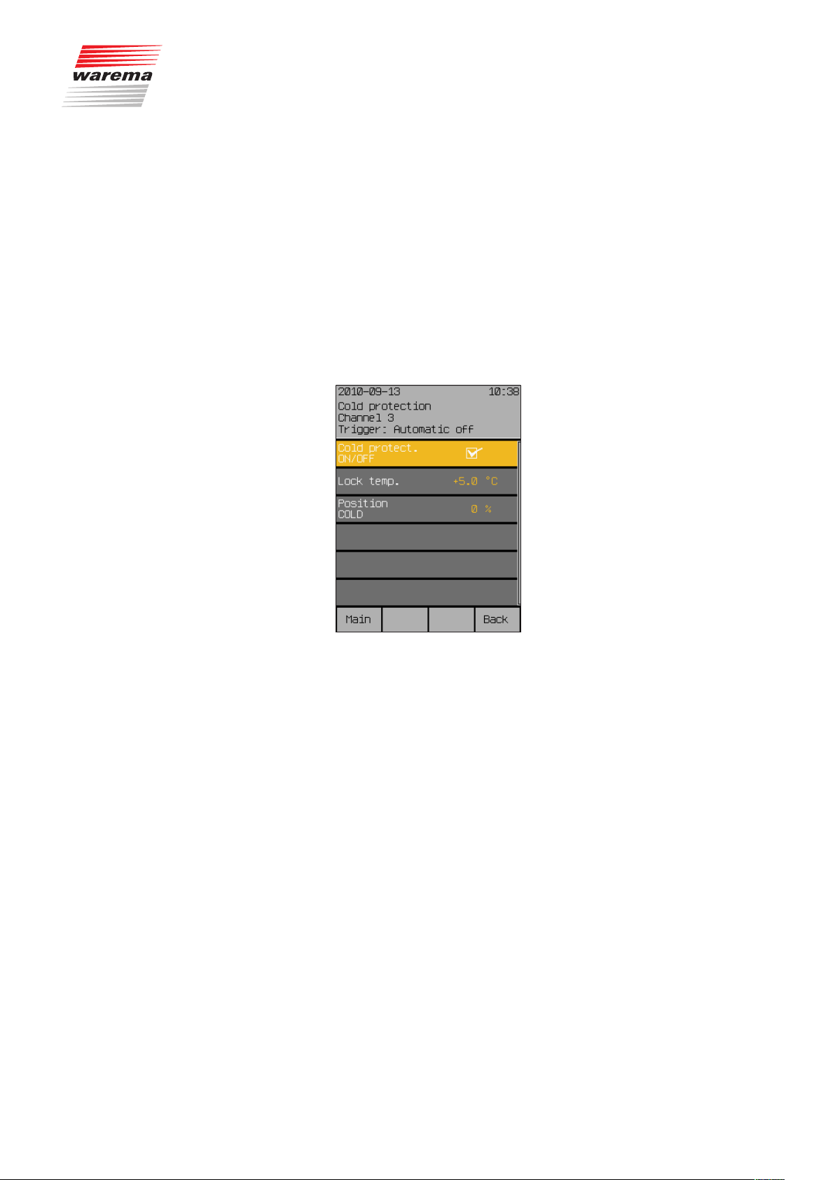
7.2.7 Cold protection
Start menu
Main menu
Settings
Comfort functions
Cold protection
Cold protection
Cold protection is another comfort function of the Wisotronic. It serves to prevent an conservatory or inside room from cooling down too much by applying intermittent ventilation or to keep a product, e.g. a window, from becoming damaged. The automatic controls are locked below an adjustable locking
temperature. The automatic controls are released again after the locking
temperature is exceeded once more by 2 °C.
NOTE Cold protection can supplement intermittent ventilation
(see Chapter 7.2.5 on page 64), for example, in a useful manner.
Press the function button [Sett.] in the main menu and go to the menu
[Comfort functions] > [Cold protection].
The following view appears in the display:
7.2.7.1 Cold protection ON/OFF
7.2.7.2 Blocking temperature
7.2.7.3 Position COLD
In this menu line, you can activate or deactivate the cold protection.
Set or delete the checkmark in the line [Cold protection ON/OFF] to acti-
vate or deactivate the cold protection.
The function button [Stand.] sets the product-specific factory setting.
The “Blocking temperature” limit value specifies the outside temperature at
which a sun shading product is to be raised, a window closed or another
product switched off. The setting range is -10...+50 °C.
Turn the touchwheel to set the value “Blocking temperature”.
The function button [Stand.] sets the value for the blocking temperature to
+5 °C (factory setting).
The “Position COLD” value specifies the position to which the sun shading
product of the channel should be moved when the temperature falls below
the locking temperature. The setting range is 0-100%; a value of 0% corresponds to the upper limit position and a value of 100% to the lower limit
position.
Turn the touchwheel to set the value "Position COLD".
The function button [---] leaves the position unchanged when falling
below the locking temperature; function button [Stand.] sets the productspecific factory setting).
890557_d•en•01.07.2014 We reserve the right to carry out improvements
71
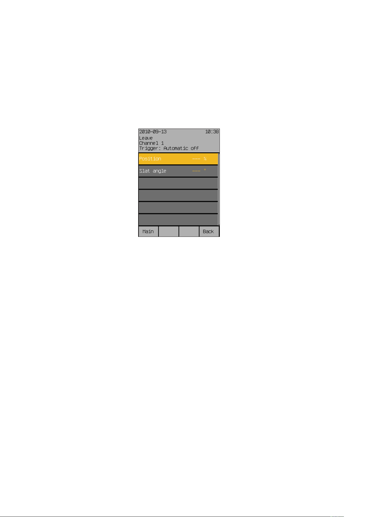
Leave
7.2.8 Leave
Start menu
Main menu
Settings
Comfort functions
Leave
Wisotronic 1-channel
Operating instructions
This menu allows you to set the position of the sun shading product and, if
applicable, the inclination (angle) of the slats during your leave. The move
command is executed once at the beginning of your leave.
Press the function button [Sett.] in the main menu and go to the
[Comfort functions] > [Leave] menu.
The following view appears in the display:
7.2.8.1 Position
7.2.8.2 Slat angle
The "Position" value specifies the position to which a sun shading product is
to move at the beginning of your leave. The setting range is 0-100%; a value
of 0% corresponds to the upper limit position and a value of 100% to the
lower limit position.
Turn the touchwheel to set the value “Position”.
The function button [---] sets the value for the position to [---]; the function
button [Stand.] sets the value also to [---], i.e. the position of the sun shading product remains unchanged (factory setting).
In this menu line, you specify how the angle of the slats are to be set at the
beginning of your leave. The setting range is from -360° to +360°. External
venetian blinds normally have a setting range from -80° to +80°.
Turn the touchwheel to set the value "Slat angle".
The function button [---] leaves the slat angle unchanged; function button
[Stand.] sets the factory setting.
We reserve the right to carry out improvements
72
890557_d•en•01.07.2014
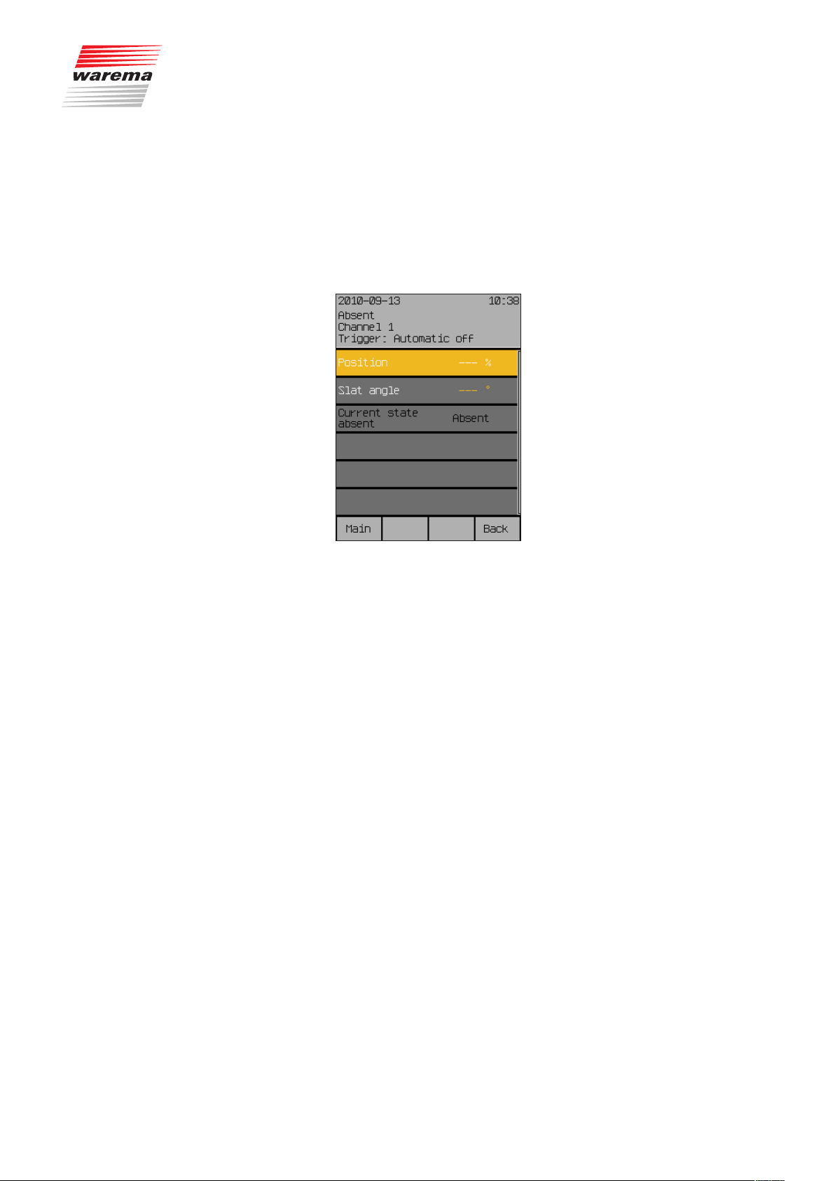
7.2.9 Absent
Start menu
Main menu
Settings
Comfort functions
Absent
Absent
This menu allows you to set the position of the sun shading product and, if
applicable, the inclination (angle) of the slats during your absence. The move
command is executed once at the beginning of your absence.
Press the function button [Sett.] in the main menu and go to the
[Comfort functions] > [Absent] menu.
The following view appears in the display:
7.2.9.1 Position
7.2.9.2 Slat angle
7.2.9.3 Current state absent
The “Position” value specifies the position to which a sun shading product
is to move at the beginning of your absence. The setting range is 0-100%; a
value of 0% corresponds to the upper limit position and a value of 100% to
the lower limit position.
Turn the touchwheel to set the value “Position”.
The function button [---] sets the value for the position to [---]; the function
button [Stand.] sets the value also to [---], i.e. the position of the sun shading product remains unchanged (factory setting).
In this menu line, you specify how the angle of the slats are to be set at the
beginning of your absence. The setting range is from -360° to +360°. External venetian blinds normally have a setting range from -80° to +80°.
Turn the touchwheel to set the value "Slat angle".
The function button [---] leaves the slat angle unchanged; function button
[Stand.] sets the factory setting.
The "Current state absent" line shows the current status of the absent parameter and is for informational purposes only.
890557_d•en•01.07.2014 We reserve the right to carry out improvements
73

Manual operation
7.2.10 Manual operation
Start menu
Main menu
Settings
Comfort functions
Manual operation
Wisotronic 1-channel
Operating instructions
In this menu you can perform settings affecting the manual operation when
you jump from the main menu to the operating menu for the channel by
pressing the touchwheel.
In the main menu, press the function button [Sett.]. Now proceed to the
menu [Comfort functions] > [Manual operation].
The following view appears in the display:
7.2.10.1 Position DOWN
7.2.10.2 Slat angle DOWN
The value “Position DOWN” specifies to which position the sun shading product should move with manual operation through the function button “Down”.
The setting range is 0-100%; a value of 0% corresponds to the upper limit
position and a value of 100% to the lower limit position.
Turn the touchwheel to set the value “Position DOWN”.
The function button [---] leaves the position unchanged; the function button
[Stand.] sets the value for the “Position DOWN” to the factory setting.
NOTE When the function button “DOWN” is pressed again while the sun shading
product is lowered, it always moves to 100% (lower limit position).
This setting is only useful when you have chosen a slat product (external or
internal venetian blinds). If you have connected a slat product, such as external venetian blinds, to a channel, you can specify how the slats are to be
set to the "DOWN" position after the movement has been completed. This
is especially useful if you prefer a specific setting. In addition, you must no
longer tilt the slats manually after a move. The Wisotronic tilts the slats if programmed accordingly.
Turn the touchwheel to set the value "Slat angle DOWN".
The function button [---] leaves the slat angle unchanged; the function button [Stand.] sets the value “Slat angle DOWN” to the factory setting.
We reserve the right to carry out improvements
74
890557_d•en•01.07.2014

7.2.10.3 Holding time hh:mm
7.2.10.4 The manual operation
options
Function buttons,
touchwheel
Manual operation
The holding time is used to set how long the comfort functions are to be
disabled after manual operation. The setting range is 00:00 to 24:00 hours.
Manual operation can thereby be performed on the control panel by channel
or group as well as by product or for a local group on the local pushbutton.
Turn the touchwheel to set the value “Holding time hh:mm”. Pressing on the
wheel causes the display to jump to minutes. Set the minutes in the same
manner.
The function button [Stand.] sets the holding time to the factory setting.
NOTE A timer command deletes the manual holding time.
With the function buttons and the touchwheel
When a comfort function has triggered a move command, counter-control or
stopping is possible.
When a safety function has been triggered, neither counter-controlling nor
stopping is possible.
Hand-held transmitter
External pushbutton
device
Operation is possible at an time (as long as no safety function has triggered
an alarm), regardless of the view in the display of the control
When a comfort function has triggered a move command, counter-control or
stopping is possible.
When a safety function has been triggered, neither counter-controlling nor
stopping is possible.
Use the arrow buttons and the stop button of the hand-held transmitter to
control sun shading products. Slat products operate based on the radio time
logic (a more detailed explanation of the function principle of the radio time
logic can be found in the instructions on the hand-held transmitter).
The the hand-held transmitter is assigned to a scene, the scene can be
opened by pressing the C button.
When external push button devices are connected to the control, the product
can be operated with these push buttons, independent of the view in the control display.
When a comfort function has triggered a move command, counter-control or
stopping is possible.
When a safety function has been triggered, neither counter-controlling nor
stopping is possible.
NOTE The function of the external push button devices is parameterisable; it can be
parameterized in such a way that it differs from the operation on the control
panel or is more restricted.
890557_d•en•01.07.2014 We reserve the right to carry out improvements
75
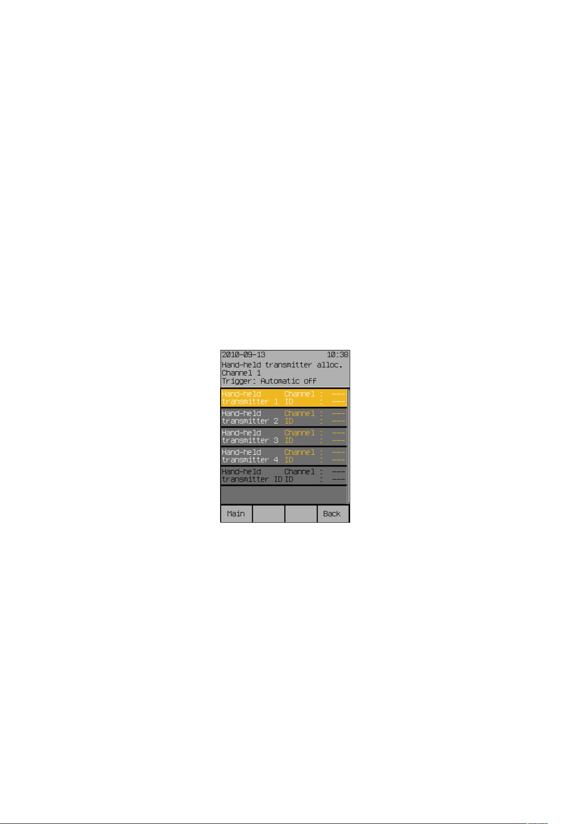
Hand-held transmitter
7.2.11 Hand-held transmitter
allocation
Start menu
Main menu
Settings
Comfort functions
Hand-held transmitter allocation
NOTE The WAREMA range includes transmitters in an enclosure for wall mounting.
NOTE Each hand-held transmitter channel can only be assigned once in the Wiso-
The WAREMA EWFS Hand-held transmitters can be used to manually operate the sun shading products connected to Wisotronic.
Read the operating instructions of the EWFS Hand-held transmitter prior to its
first use.
You can use several EWFS Hand-held transmitters (1-channel or 8-channel),
assign one of the 4 hand-held transmitter channels or delete hand-held transmitters already assigned.
These EWFS Wall-mounted transmitters have exactly the same functions as
the EWFS Hand-held transmitters described here and can be used as an alternative or in addition.
tronic.
Press the function button [Sett.] in the main menu and go to the menu
[Comfort functions] > [Hand-held transmitter allocation].
The following view appears in the display:
Wisotronic 1-channel
Operating instructions
We reserve the right to carry out improvements
76
890557_d•en•01.07.2014

7.2.11.1 Hand-held transmitter 1
7.2.11.2 Hand-held transmitter 2,3,4
Hand-held transmitter
In this menu line, you can assign the first radio transmitter to the channel of
the Wisotronic or delete a radio transmitter already assigned again.
Use the touchwheel to select the [
turning and pressing it. (The terms "Channel: --- and ID: --- change their
colour).
Select the desired channel (1...8) on the hand-held transmitter if you want to
allocate the 8-channel version of the EWFS Hand-held transmitter.
If you have not yet done so, open the battery compartment of your EWFS
Hand-held transmitter and press the L learn button in the battery compartment.
The channel and the ID (serial number) of the EWFS Hand-held transmitter is
now shown on the right in the display.
The [Delete] function button deletes this assignment again; the [Cancel]
function button cancels the change.
Proceed as follows to learn in additional EWFS Hand-held transmitters:
Move the selection curve and selection bar with the touchwheel to the cor-
responding line and proceed as described in 7.2.11.1.
Hand-held transmitter 1] menu line by
7.2.11.3 Hand-held transmitter
identifier
This menu line is for display purposes only. When you press a button on a
hand-held transmitter, the channel and the ID are displayed there at the right
for approx. 1 second to confirm the reception. After you have activated one
of the four upper lines by pressing the touchwheel, these values are accepted for that location.
890557_d•en•01.07.2014 We reserve the right to carry out improvements
77

Channels, groups, scenes
7.3 Manage channels,
groups, scenes
Start menu
Main menu
Settings
Manage channels, groups, scenes
The menus are used to combine channels to groups that can be operated
together, to define valid scenes for a specific time and to adapt the names of
channels, groups and scenes to your preferences and needs. Furthermore,
you can sort the order of the channels, groups and scenes in the main menu
according to your preferences.
Press the function button [Sett.] in the main menu and then go to the menu
[Manage channels, groups, scenes].
The following view appears in the display:
Wisotronic 1-channel
Operating instructions
7.3.1 Manage groups
Start menu
Main menu
Settings
Manage channels, groups, scenes
Manage groups
Making a selection with the touchwheel guides you to the following submenus:
The collection of channels to groups is only possible in Wisotronic models
with multiple channels. Therefore, the [Manage groups] menu is not available
for the Wisotronic 1-channel.
We reserve the right to carry out improvements
78
890557_d•en•01.07.2014
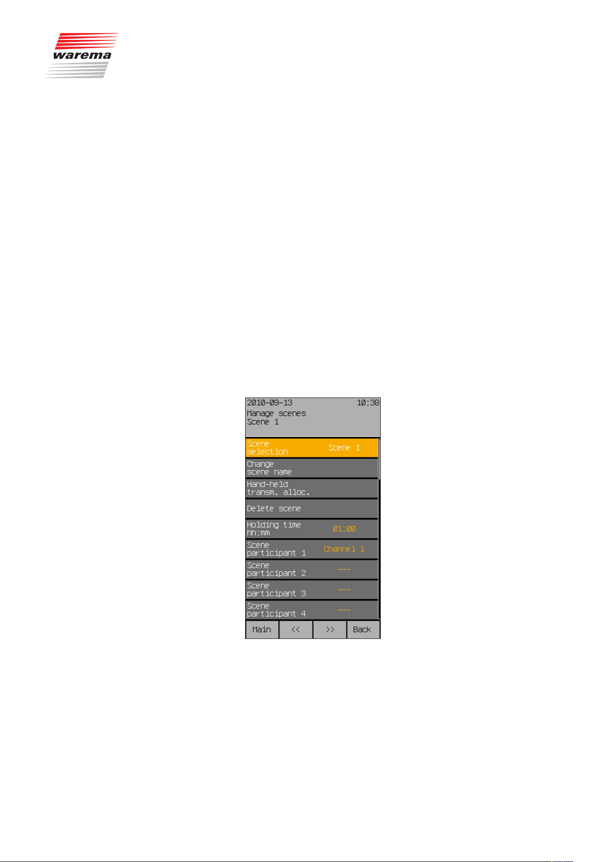
7.3.2 Manage scenes
Start menu
Main menu
Settings
Manage channels, groups, scenes
Manage scene
Channels, groups, scenes
Any states can be stored in a scene and retrieved at any time. For a set
holding time you access positions previously learned. However, during the
holding time of the scene, the set positions can be by-passed manually or
through safety functions; after the holding time has expired the set automatic
modes assume the control of the connected products again.
Up to four scenes can be created.
NOTE Once you have created a scene as described below, you must still learn
them in the main menu. Proceed as follows for this purpose:
Move/switch manually to the desired position.
In the main menu, select the line [Scene 1] (or the name of the scene you
specified).
Select the menu item [Learn scene] by pressing the touchwheel; pressing
starts the learning process.
You can now select the [Scene 1] scene (or the name of the scene you
specified) from the main menu by turning and pressing the touchwheel and
call up the corresponding scene in the [Scene 1] menu.
The following options are available to managing the scenes:
NOTE The [<<] and [>>] buttons can be used to change between the four scenes,
regardless of the menu line in which you are currently located. The currently
selected scene is always shown in the header.
890557_d•en•01.07.2014 We reserve the right to carry out improvements
79

Channels, groups, scenes
7.3.2.1 Scene selection
Select scene 1 to 4 in this menu line.
Turn the touchwheel to select the desired scene (the scenes change when
turning and are displayed at the right in the menu line).
NOTE The [<<] and [>>] buttons can also be used to change between the four
scenes.
7.3.2.2 Change scene name
In this menu line you change the scene name (also called “alias”) for the selected scene.
With the touchwheel select the menu line [Change scene name].
The following view appears in the display:
Wisotronic 1-channel
Operating instructions
You will see the current scene name in the white input field and the blinking
cursor at the right. The available characters are shown in the selection field
below it. The so-called “Alias name” of the scene may consist of upper case
letters, lower case letters, numbers and symbols.
You can change the alias names of a scene:
Turn the touchwheel to select a symbol from the lower frame.
Press the touchwheel to enter the selected symbol in the input field.
Push the function button [
of the blinking cursor).
Press the touchbutton [A/a/1] to switch between upper and lower case or
numbers and special characters.
Enter the desired name in this manner and then push the [Back] function but-
ton.
This returns you to the window [Manage scenes].
NOTE You can enter a maximum of 28 characters (2 lines of 14 characters each).
If there are more than 14 characters, the name is displayed in two parts. To
avoid a line break in the middle of a word, you can fill the end of the first line
with spaces, if necessary.
] to delete a symbol in the input field (to the left
We reserve the right to carry out improvements
80
890557_d•en•01.07.2014

7.3.2.3 Hand-held transmitter
allocation
7.3.2.4 Delete scene
7.3.2.5 Holding time hh:mm
Channels, groups, scenes
In this menu line you can assign radio transmitters to a scene. Proceed as
described in Chapter 7.2.11 on page 76 for a channel.
You can call up the scene by pressing button C on the assigned transmitter.
In this menu line you delete a scene you have created again.
With the touchwheel select the menu line [Delete scene].
The following warning appears on the right: [Delete scene?].
Press the touchwheel once more for deletion.
In this menu line you set the so-called "Holding time" where a called scene is
held for the holding time duration. During this holding time, no comfort functions are carried out on the affected channels. However, manual operation
and safety functions can by-pass this scene.
The setting range is 00:00 to 24:00 hours.
NOTE If switching time commands are received while the holding time runs down,
they are executed after the holding time has expired.
7.3.2.6 Scene member 1
7.3.2.7 Scene member 2 to 4
NOTE The following applies to a disabled product: If the global automatic control
has been deselected in the main menu, the last move command is not repeated when the lock is cancelled (after a scene, leave or absence).
Turn the touchwheel to set the hours of the "Holding time hh:mm" value.
Pressing on the wheel causes the display to jump to minutes. Set the minutes in the same manner.
The function button [Stand.] sets the holding time to the factory setting.
In this menu line, assign one channel to the current scene, allowing you to
call it up later with the scene.
Select the [Scene member 1] menu line with the touchwheel and press the
touchwheel.
Select the desired channel now by turning the touchwheel. The channel is
assigned to the scene by subsequently pressing the touchwheel.
The function button [Delete] removes the channel assignment.
NOTE Because Wisotronic 1-channel has only one channel, only channel 1 or ---
can be selected here.
These functions are not enabled since Wisotronic 1-channel has only one
channel.
890557_d•en•01.07.2014 We reserve the right to carry out improvements
81

Channels, groups, scenes
7.3.3 Sort channels, groups,
scenes
Start menu
Main menu
Settings
Manage channels, groups, scenes
Sort channels, groups, scenes
In this menu you will see the same list of all channels and scenes as in the
main menu:
Wisotronic 1-channel
Operating instructions
7.3.4 Change alias names
Start menu
Main menu
Settings
Manage channels, groups, scenes
Change alias name
Here you can sort the sequence of the lines as follows and as desired:
Select the menu line you want to move with the touchwheel.
The function button [Lower] sorts the current channel or scene one line
down; the line originally below it moves up.
The function button [Upper] sorts the current channel or scene one line up;
the line originally above it moves down.
Select the next menu line you want to move with the touchwheel and pro-
ceed as above.
After all lines are in the desired sequence, you return to the menu
[Manage channels, groups, scenes] with the function button [Back].
In this menu you can change the so-called “Alias names” for all channels
and scenes. These are either the factory defaults “Channel1”, "Scene1",
etc., or the names assigned by you.
In this menu you will see the same list of all channels and scenes as in the
main menu:
We reserve the right to carry out improvements
82
Select the menu line you want to rename with the touchwheel.
890557_d•en•01.07.2014

Channels, groups, scenes
The following view appears in the display:
The heading indicates whether this is a channel or a scene. You will see the
current name in the white input field and the blinking cursor at the right. The
available characters are shown in the selection field below it. The so-called
“Alias name” may consist of upper case letters, lower case letters, numbers
and symbols.
How to change a name:
Turn the touchwheel to select a symbol from the lower frame.
Press the touchwheel to enter the selected symbol in the input field.
Push the function button [
of the blinking cursor).
Press the touchbutton [A/a/1] to switch between upper and lower case or
numbers and special characters.
Enter the desired name in this manner and then push the [Back] function but-
ton.
This returns you to the window [Change alias names].
] to delete a symbol in the input field (to the left
NOTE You can enter a maximum of 28 characters (2 lines of 14 characters each).
If there are more than 14 characters, the name is displayed in two parts. To
avoid a line break in the middle of a word, you can fill the end of the first line
with spaces, if necessary.
890557_d•en•01.07.2014 We reserve the right to carry out improvements
83
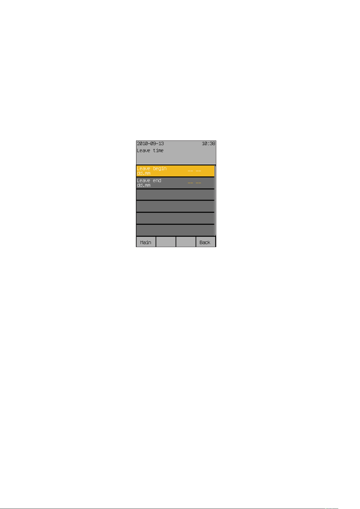
Leave time
7.4 Leave time
Start menu
Main menu
Settings
Leave time
Wisotronic 1-channel
Operating instructions
Enter the beginning and end of your leave in this menu. The automatic controls set at the comfort functions for the leave are then active during this
time. The products drive to a specific position (and possible slat angle) at the
beginning of your leave if you have activated this settings in the comfort functions of the respected channels.
In the main menu, press the [Sett.] function button. Now go to the [Leave]
menu.
The following view appears in the display:
7.4.1 Leave begin dd.mm
7.4.2 Leave end dd.mm
In this menu line, you set the day and month of the beginning of your leave.
The setting range reaches from 01.01. to 31.12.
Turn the touchwheel to set the day of the “Leave begin hh:mm” value. A
push on the touchwheel causes the display to jump to the month. Set the
month in the same manner.
Accept the value by pressing the touchwheel.
The function button [Delete] removes the setting [--.--].
NOTE The leave time is only taken into account by the Wisotronic when you have
entered a date for the beginning and the end of the leave.
In this menu line, you set the day and month of the end of your leave. The
setting range reaches from 01.01. to 31.12.
Turn the touchwheel to set the day of the “Leave end hh:mm” value. A push
on the touchwheel causes the display to jump to the month. Set the month
in the same manner.
Accept the value by pressing the touchwheel.
The function button [Delete] removes the setting [--.--].
We reserve the right to carry out improvements
84
890557_d•en•01.07.2014
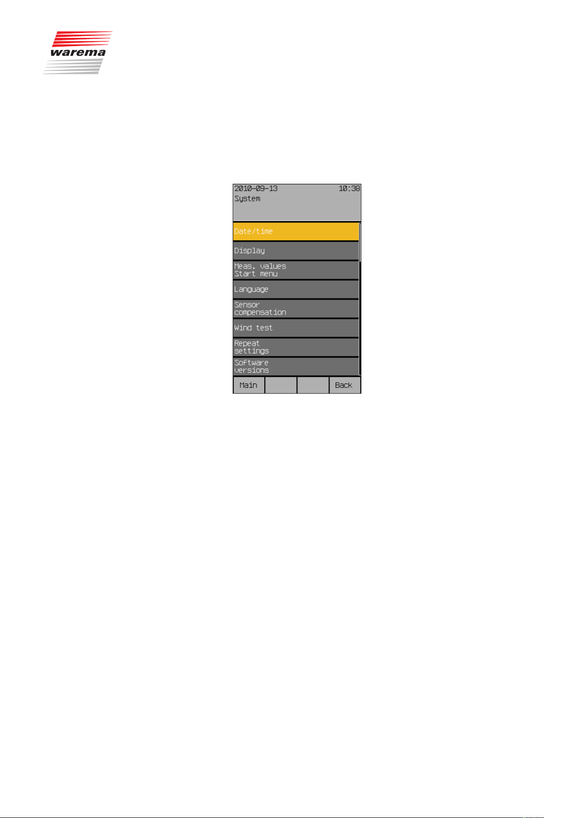
7.5 System settings
Start menu
Main menu
Settings
System
System settings
In this menu you perform basic settings for the control and the sensors.
Press the [Sett.] function button in the main menu and then go to the
[System] menu.
The following view appears in the display:
890557_d•en•01.07.2014 We reserve the right to carry out improvements
85

System settings
7.5.1 Date / time
Start menu
Main menu
Settings
System
Date/Time
Wisotronic 1-channel
Operating instructions
Set the date and time of the Wisotronic in this menu:
Press the function button [Sett.] in the main menu and then go to the
[System] > [Date / time] menu.
The following view appears in the display:
Set the time in 24-hour format in the first menu line.
Turn the touchwheel to set the hours of the "Time hh:mm" value. Pressing on
the wheel causes the display to jump to minutes. Set the minutes in the same
manner.
Accept the value by pressing the touchwheel.
The function button [Stand.] sets the hours to 12, the minutes to 30 (factory
setting).
Now select the line [Day] by turning the touchwheel and enter the day in the
same manner. Proceed in the same manner with month, year and weekday.
After you have selected the [Standard time/daylight sav.] menu line,
one rotation increment of the touchwheel to the left sets the standard time;
one rotation increment to the right sets the daylight saving time.
The [Standard time/daylight auto] and [Use DCF77] functions can be ac-
tivated or deactivated by setting or deleting the checkmark.
NOTE The DCF-77 time signal is only available if you are using a suitable sensor.
This function is not available at this time. Ensure that the "Use DCF77" function is deactivated.
The new settings for date and time have now been set.
Pushing the function button [Back] returns you to the menu [System].
We reserve the right to carry out improvements
86
890557_d•en•01.07.2014
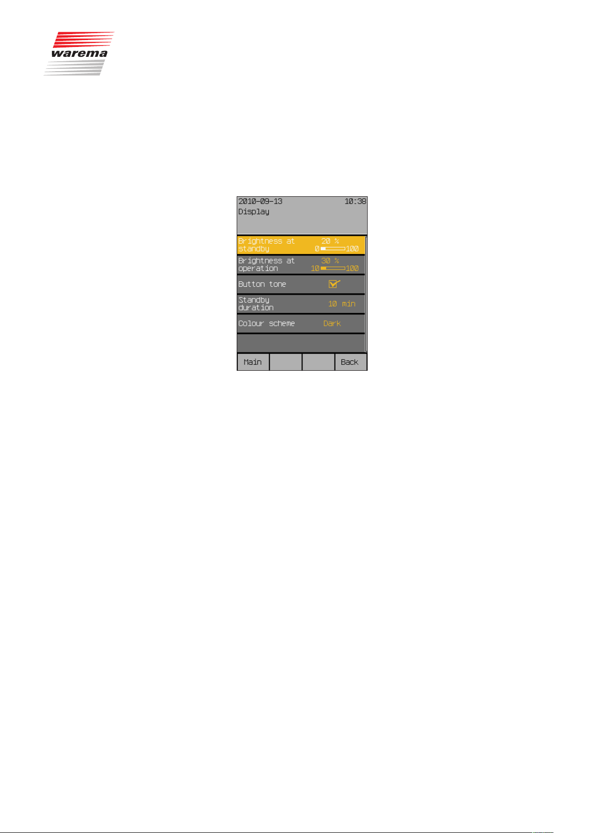
7.5.2 Display
Start menu
Main menu
Settings
System
Display
System settings
In this menu you adjust the view of the display or change the behaviour of
the operating elements.
Press the [Sett.] function button in the main menu and then go to the
[System] > [Display] menu.
The following menu is displayed:
7.5.2.1 Brightness at standby
7.5.2.2 Brightness at operation
The display is normally set by the factory for easy readability. However, you
can adjust it here to your personal needs and to the light incidence at the
installation location.
If the Wisotronic is not operated for longer than 3 minutes, the display is set
to a freely adjustable brightness value (e.g. darkened).
Set this [Brightness at standby] in the first menu line:
Press the touchwheel; the value on the right becomes editable and the dis-
play is dimmed to the indicated value.
By turning the touchwheel to the right or left, the bar moves and the bright-
ness is increased or reduced.
You will see the effects by the change of the display. If you select a setting
below 10% (OFF is displayed), the display will go completely dark after 3
minutes. The brightness is increased by turning the touchwheel in a clockwise direction.
The [Stand.] function button sets the factory setting of 20%.
Set the [Brightness at operation] in the same manner in the next menu line. The brightness during operation can be reduced to a minimum level of 10%. Darkening the display completely during operation is counterproductive.
The factory setting ([Stand.] function button) is 30%.
890557_d•en•01.07.2014 We reserve the right to carry out improvements
87

System settings
7.5.2.3 Button tone
7.5.2.4 Standbyduration
7.5.2.5 Display behaviour of
Wisotronic
Wisotronic 1-channel
Operating instructions
You change the behaviour of the function buttons in the line [Button tone].
Turning the touchwheel sets or deletes the checkmark at the right, thereby
activating or deactivating the actuation tone of the function buttons.
The [Stand.] function button sets the factory setting.
After 15 minutes without manual operation in the operator mode, the display
changes to standby mode.
The duration of standby mode is selected in the [Standby duration] menu
item. The time can be set in the range of 1 to 240 min.
[Brightness at operation]
(10...100%)
[Brightness at standby]
(OFF, 10...100%)
0 3 15 16...255
cedure
brightness
Dim to standby
Last operating pro-
Fig. 16 Display behaviour
[Standby mode]
menu
Change to standby
mode, display Start
[Standby duration]
(1...240min)
—
Activate screen sav-
er, display time
Minutes
We reserve the right to carry out improvements
88
890557_d•en•01.07.2014

7.5.2.6 Colour scheme
System settings
With [Colour scheme], you can change the colours of the display. Two colour schemes are available: "dark" and "light".
Dark colour scheme Light colour scheme
Select the desired scheme in the [Colour scheme] menu line by turning and
pressing the touchwheel.
Pushing the function button [Back] returns you to the menu [System].
890557_d•en•01.07.2014 We reserve the right to carry out improvements
89

System settings
7.5.3 Measured values start
menu
Start menu
Main menu
Settings
System
Measured values start menu
Wisotronic 1-channel
Operating instructions
In this menu you can define which measured values are displayed in the
Start menu. You can select which sensors are to be evaluated.
Press the [Sett.] function button in the main menu and then go to the
[System] > [Measured values start menu].
The following menu is displayed:
Here you can assign the desired sensors to the four measured values that
appears in the Start menu. For each measured value, only the sensors that
are actually available are offered for selection.
Using the touchwheel, select a measured value and assign a sensor from
the displayed selection.
The [Delete] function button removes the currently assigned sensor and
[---] is displayed. This measured value no longer appears in the Start menu.
The [Stand.] function button resets the selection to the default assignment.
The [Canc.] function button is used to leave the selection menu without making a change.
Pushing the function button [Back] returns you to the menu [System].
We reserve the right to carry out improvements
90
890557_d•en•01.07.2014

7.5.4 Language
Start menu
Main menu
Settings
System
Language
System settings
Set the operating language of the Wisotronic in this menu.
Press the function button [Sett.] in the main menu and then go to the menu
[System] > [Language].
The following view appears in the display:
At the time of printing of these instructions, the following languages were implemented as operating languages.
German
English
French
Spanish
Italian
Norwegian
To set the operating language, toggle between the available languages by
turning the touchwheel.
Press the touchwheel to confirm your selection.
NOTE When the power supply returns after an interruption, the Start menu appears
in the display in the language last selected.
890557_d•en•01.07.2014 We reserve the right to carry out improvements
91
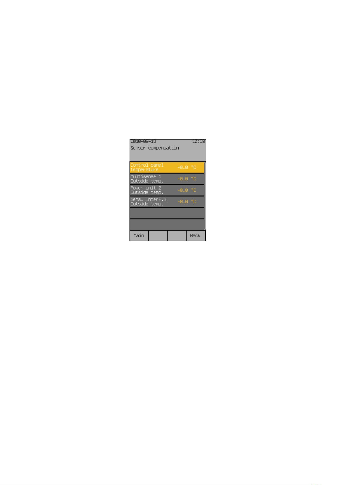
System settings
7.5.5 Sensor compensation
Start menu
Main menu
Settings
System
Sensor compensation
Wisotronic 1-channel
Operating instructions
This menu serves to compare the internal and external temperature measuring values of your Wisotronic with the temperature prevailing at the installation locations. This may become necessary if a sensor was mounted in an
unfavourable location (such as in the vicinity of a heat source or in direct
sunlight).
Press the function button [Sett.] in the main menu and then go to the menu
[System] > [Sensor compensation] menu.
The following menu appears where the max. possible number of sensors for
temperature is indicated:
7.5.5.1 Control panel temperature
7.5.5.2 Weather station 1 (2,3)
outside temperature
NOTE Weather stations 2 and 3 are not available for Wisotronic 1-channel.
NOTE When commissioning, note that the multisense weather station has an inter-
The [Control panel temperature] value specifies by how many degrees Celsius the measured value of the internal sensor of the Wisotronic is corrected up or down. The setting range is –10°C to +10°C.
Turn the touchwheel to set the value [Control panel temperature].
The [Stand.] function button sets the value to the factory setting.
Multisense 1 Outside temperature] value specifies by how many
The [
degrees Celsius the measured value of weather station 1 is corrected up or
down. The setting range is –30...+10°C.
Turn the touchwheel to set the value [
The [Stand.] function button sets the value to the factory setting.
nal temperature correction feature that improves measurement accuracy. The
device follows temperature changes at a rate of approx. 10min per °C.
When the Wisotronic is first switched on, the first temperature measurement
is taken at the multisense weather station. If the weather station was previously stored at a considerably lower or higher temperature, it may take several hours before the correct temperature is displayed.
If the weather station is already at the temperature of its environment when
the Wisotronic is first switched on, the actual temperature measurement
value will be displayed from the start.
Multisense 1 Outside temp.].
We reserve the right to carry out improvements
92
890557_d•en•01.07.2014
7.5.6 Wind test
7.5.7 Restore settings
Start menu
Main menu
Settings
System
Restore settings
System settings
This function is actually a repetitive check of the wind sensors connected
to the Wisotronic. A description can be found in the installation instructions,
Chapter 8.1.5.
This menu line serves to restore the settings made by the specialist dealer
during commissioning.
NOTE To be able for you to restore the service settings, it is necessary that the spe-
cialist dealer saves the settings made during commissioning.
CAUTION
When you restore the service settings, your individual settings are lost.
Press the [Sett.] function button in the main menu and then go to the
[System] > [Restore settings] menu.
The following questions appears on the left in the menu line:
[From service setting?]
Pressing on the [YES] button or on the touchwheel adopts the service set-
tings. [Please wait...] appears briefly on the right for several seconds and
then disappears. The service settings have been restored.
NOTE If the special dealer did not save the settings, the following message appears
on the right in the menu line: [Service settings not stored.]
After the service settings are restored, the [Load data in actuator] menu
appears.
Press the touchwheel to finish adoption of the service settings.
After the loading process is completed, the [System] menu appears again.
890557_d•en•01.07.2014 We reserve the right to carry out improvements
93

Software versions
7.5.8 Software versions
Start menu
Main menu
Settings
System
Software versions
Wisotronic 1-channel
Operating instructions
The software versions of all device components and the connected devices
are displayed in this menu. This information is helpful, for example, if you
want to expand your sun shading control system or if a problem has occurred with your control. You can then provide this data to your dealer on the
phone.
The software versions are only displayed; they cannot be edited.
We reserve the right to carry out improvements
94
890557_d•en•01.07.2014

7.6 Sensor allocation
Start menu
Main menu
Settings
Sensor allocation
7.7 Clean control panel
Start menu
Main menu
Settings
Clean control panel
Cleaning
In this menu, you can view the assignments of the sensors to the measuring
variables. The dealer performs these settings for you during commissioning.
Changes can only be made after entering the service password.
NOTE Please contact your specialist dealer if you wish to make changes to this
item.
This menu facilitates cleaning of the control panel. The display is thereby
largely cleared to be able to better see dirt contamination. The function buttons are deactivated.
In the main menu, press the [Sett.] function button. Then select
[Clean control panel].
The following view appears in the display:
CAUTION
When cleaning, it is imperative that you follow the instructions in
Chapter 9 on page 104!
890557_d•en•01.07.2014 We reserve the right to carry out improvements
95
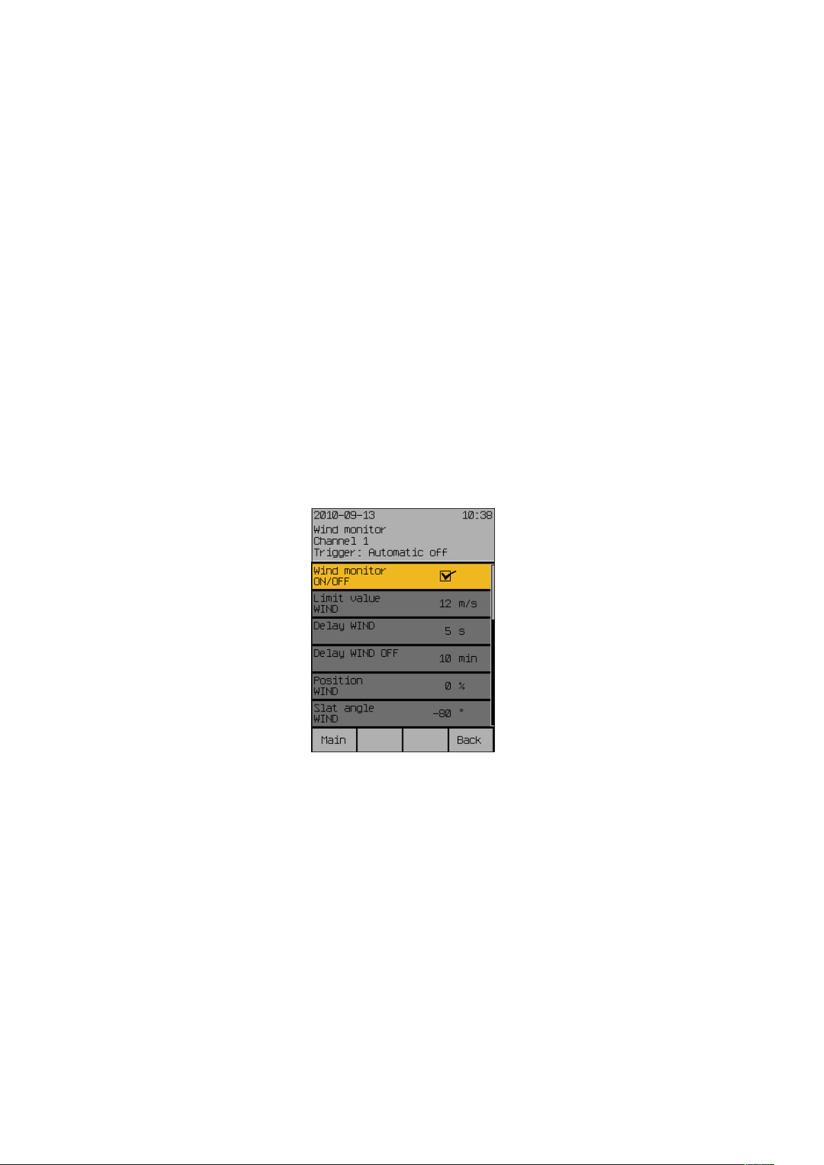
Safety functions
7.8 Service
Start menu
Main menu
Settings
Service
7.9 Safety functions
7.9.1 Wind monitoring
Start menu
Main menu
Settings
Safety functions
Wind monitor
Wisotronic 1-channel
Operating instructions
This menu is reserved for service or the specialist dealer who will commission the Wisotronic for you or with you. An access password must be entered
here permitting the specialist dealer to set up the project (creation and parameterisation of channels and safety functions).
NOTE If you would like to have changes made to the configuration of your Wiso-
tronic, please contact your specialist dealer.
The wind monitor safety function prevents destruction of your sun shading
products by wind by moving them early enough to a safe position. Your dealer will set the required limit values and delay times for you during installation.
You can view these settings as follows:
Press the function button [Sett.] in the main menu and go to the
[Safety functions] > [Wind monitor] menu.
The following view appears in the display:
We reserve the right to carry out improvements
96
The settings of the wind control are only displayed; they cannot be edited.
890557_d•en•01.07.2014

7.9.2 Ice monitor
Start menu
Main menu
Settings
Safety functions
Ice monitor
Safety functions
The ice monitoring safety function prevents destruction of your sun shading
products through movements when, for example, the guide rails are frozen.
An ice alarm can be reset automatically and/or manually.
Press the function button [Sett.] in the main menu and go to the
[Safety functions] > [Ice monitor] menu.
The following view appears in the display (the header may show the channel
name you selected instead of Channel 1 and the setting values in the right
column may be different:
7.9.2.1 Automatic reset ice alarm?
NOTE To ensure that the product is not damaged, the ice alarm is not reset until the
In this menu line, you specify whether the ice monitor is to reset an ice alarm
automatically. The automatic comfort controls and the manual operation are
enabled again when the conditions for an ice alarm no longer exist.
Set or delete the checkmark in the line [Reset ice alarm automatically]
to activate or deactivate the automatic reset of an ice alarm.
outside temperature is 2°C above the preset [Limit value ICE].
890557_d•en•01.07.2014 We reserve the right to carry out improvements
97

Safety functions
7.9.2.2 Manual reset ice alarm?
7.9.2.3 Measured value outside
temp.
Wisotronic 1-channel
Operating instructions
In this menu line you can reset an ice alarm manually.
CAUTION
Ensure that your sun shading product cannot be damaged when you move it:
external venetian blinds, roller shutters and articulated arm and conservatory
awnings may be frozen. These products could be damaged if you operate
them nonetheless! If the sun shading product is operated when iced over,
any warranty and liability claims become void.
Proceed as follows to manually reset an ice alarm:
Use the touchwheel to select the [Reset ice alarm manually] line and
press the touchwheel.
The message [Ice alarm is being reset] appears briefly on the right.
The “Measured value outside temp.” line indicates the outside temperature
currently measured and is for information only.
7.9.2.4 Meas.value precipitation
The “Measured value precipitation” line indicates whether the currently measured status for precipitation and is for information only.
We reserve the right to carry out improvements
98
890557_d•en•01.07.2014
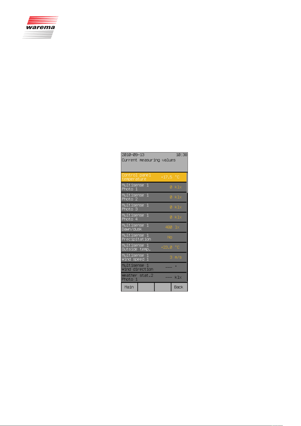
8 Measured values,
triggers and faults
8.1 Current measured
values
Start menu
Measured values
All measured values
Meas.val.
The Wisotronic has an internal memory for all measured values with the associated histories, triggers and faults. It aids with troubleshooting and is described in the following sections.
In this menu you see the current measuring values
of the connected sensors.
Press the function button [Meas.val.] in the main menu and then go to the
[Measuring values and histories] > [All measured values] menu.
The following information appears in the display (the measuring values in the
right column may be different; [---] means that the sensor does not exist):
890557_d•en•01.07.2014 We reserve the right to carry out improvements
99

Meas.val.
8.2 Measured values
history
Start menu
Measured values
All measured values
"Name of measured value"
Wisotronic 1-channel
Operating instructions
For each measured value, you can call up the measurement data as a curve.
In the main menu, select [Meas.val.] > [All measured values] >
[Control panel temperature] and press the touchwheel.
The history associated with the temperature reading is displayed.
Pressing the touchwheel again activates the cursor (a reticle) in the normal
mode.
Below the history, the measured value, the associated time and the date are
now displayed.
Turning the touchwheel moves the cursor moves back and forth (in steps of
30 minutes).
Pressing the touchwheel again switches the cursor to “fine” (steps of
10minutes) and pressing it again deactivates the cursor again.
You can use the [Week] and [Month] function buttons to also view the associated long-term temperature progressions.
When using the function button [Back] to switch to the menu
[Current measured values], you can view the histories of the other measuring values in the lines below in the same manner.
NOTE Curves and measurement data are not displayed for periods in which meas-
ured values were not recorded.
We reserve the right to carry out improvements
100
890557_d•en•01.07.2014
 Loading...