

WAREMA climatronic Installation Instructions Manual
WAREMA climatronic
®
Installation instructions
(Keep for future use.)
Sun. Light. WAREMA.Valid from 1 June 2009
890370_0
Photo: Habermaass GmbH

890370_0•en•01.06.2009
2
General information / Imprint
General information
The publication of this catalogue supersedes all previous corresponding
documentation. We reserve the right
to make alterations in the interest
of technical progress. Considerable
care was taken in producing the text
and graphics in this documentation.
No liability is accepted for any errors
which may nevertheless exist in this
documentation, nor for the consequences of any such errors.
Safety instructions
For detailed information, please refer
to the respective installation and operating instructions.
Head office
WAREMA Renkhoff SE
Hans-Wilhelm-Renkhoff-Strasse 2
97828 Marktheidenfeld/Main, Germany
P.O. Box 13 55
97822 Marktheidenfeld/Main, Germany
Phone: +49 (93 91) 20-0
Telefax: 09391/20-4299
http://www.warema.de
info@warema.de
Imprint
WAREMA Renkhoff SE
Hans-Wilhelm-Renkhoff-Strasse 2
97828 Marktheidenfeld/Main, Germany
Customer Center
Control systems
for
Export department
Phone: +49 (93 91) 20-37 40;
Fax: +49 (93 91) 20-37 49
Hotline control systems
Phone: +49 (93 91) 20-67 60;
Fax: +49 (93 91) 20-67 69
WAREMA and the WAREMA logo are
trade marks of WAREMA Renkhoff
SE.
All other brand or product names
included in this document are trade
marks or registered trade marks of
their respective owners.
© 2007, WAREMA Renkhoff SE

890370_0•en•01.06.2009 We reserve the right to carry out improvements
3
Contents
1 Legal notes ....................................................................................................... 7
2 Safety instructions ........................................................................................... 8
2.1 Meanings of symbols and pictographs ...........................................................8
2.2 Intended use .........................................................................................................9
2.3 Target group .......................................................................................................10
2.4 Retrofitting and modifications ...........................................................................10
2.5 Working safely .....................................................................................................11
2.6 Additional documents ........................................................................................12
2.7 Basic software versions .....................................................................................12
3 Introduction .................................................................................................... 13
3.1 Operating elements and interfaces .................................................................13
3.2 Principal structure of a WAREMA climatronic system .................................14
3.3 Concept ................................................................................................................15
3.3.1 Pyramid diagram of products, channels, groups, scenes ....................16
3.3.2 Channels, facades and products .............................................................17
3.3.3 Groups ............................................................................................................18
3.3.4 Scenes ............................................................................................................18
4 Installation ...................................................................................................... 19
4.1 Accessory box .....................................................................................................19
4.2 Procedure ............................................................................................................ 20
4.3 Planning the network structure .......................................................................21
4.3.1 The serial number ........................................................................................ 23
4.3.2 Sizing the power supply ............................................................................ 25
4.3.3 Use of repeaters and hubs ....................................................................... 28
4.3.4 Network cables ........................................................................................... 28
4.4 Installing the control panel .............................................................................. 28
4.5 Installing the switch actuators ........................................................................ 30
5 Connection information ................................................................................. 31
5.1 Switch actuator outputs ................................................................................... 32
5.2 Local group pushbuttons ................................................................................. 33
5.3 Allocating the products to the inputs and outputs ...................................... 34
5.4 Connection examples ...................................................................................... 35
6 Overview ......................................................................................................... 45
6.1 Elements of the display .................................................................................... 45
6.1.1 Start menu .................................................................................................... 45
6.1.2 Status display ............................................................................................... 46
6.2 Typical approaches for commissioning .........................................................47
7 Commissioning ............................................................................................. 48
7.1 Setting the operating language ...................................................................... 48
7.2 Project setup with the assistant ..................................................................... 49
7.2.1 Creating a sensor ........................................................................................51
7.2.2 Identifying a sensor .................................................................................... 52
7.2.3 Creating actuators ...................................................................................... 55
7.2.4 Identifying actuators .................................................................................... 56
7.2.5 Creating channels ........................................................................................ 59
7.2.5.1 Assigning name for channel X ............................................................ 59
7.2.5.2 Selecting a product type ..................................................................... 60
7.2.5.3 Setting the number of products to be controlled together ............ 60
7.2.5.4 Selecting an external venetian blind type .........................................61
Table of contents

890370_0•en•01.06.2009
We reserve the right to carry out improvements
4
Contents WAREMA climatronic®
Installation Instructions
7.2.5.5 Setting run times and tilting steps .................................................... 62
7.2.5.6 Activating the safety functions ........................................................... 63
7.2.5.7 Activating the comfort functions ........................................................ 64
7.2.5.8 Allocating sensors ............................................................................... 64
7.2.5.9 Learning in the hand-held transmitter ............................................... 65
7.2.6 Additional channel? .................................................................................... 66
7.2.7 Locking contacts ........................................................................................ 66
7.2.8 Setting the date and time .......................................................................... 67
7.2.9 Allocating outputs ....................................................................................... 68
7.2.10 Applying settings and closing the assistant .......................................... 70
8 Manual commissioning ................................................................................. 72
8.1 Creating system settings .................................................................................. 72
8.1.1 Date and time .............................................................................................. 72
8.1.2 Display settings ............................................................................................ 73
8.1.2.1 Display behaviour of the climatronic...................................................74
8.1.2.2 Creating and loading a standby picture .............................................74
8.1.3 Selecting the language ............................................................................... 76
8.1.4 Sensor compensation ................................................................................ 77
8.1.4.1 Control panel temperature .................................................................. 77
8.1.4.2 Weather station 1 (2,3) outside temperature .................................. 77
8.1.4.3 Humidity/temperature 1 (2) temperature ......................................... 78
8.1.5 Geographical position ............................................................................... 78
8.1.6 Absent ...........................................................................................................81
8.1.7 Wind test ...................................................................................................... 82
8.1.8 Authorised dealer access ......................................................................... 83
8.1.9 Display all menus ....................................................................................... 84
8.2 Manage actuators ............................................................................................. 85
8.3 Channels ............................................................................................................ 86
8.3.1 Comfort functions ....................................................................................... 87
8.3.2 Safety functions .......................................................................................... 87
8.3.2.1 Wind monitor ......................................................................................... 88
8.3.2.2 Ice monitor ............................................................................................. 95
8.3.2.3 Building control system ....................................................................... 97
8.3.3 Sensor allocation ......................................................................................... 98
8.4 Manage products ........................................................................................... 100
8.4.1 Product type .............................................................................................. 101
8.4.2 Copy settings from... ................................................................................ 101
8.4.3 Delete product .......................................................................................... 101
8.4.4 Channel allocation .................................................................................... 101
8.4.5 Contact allocation, Number of contacts .............................................. 101
8.4.6 Locking contact ........................................................................................ 102
8.4.7 Runtime UP mm:ss .................................................................................. 103
8.4.8 Runtime DOWN mm:ss/On period mm:ss .......................................... 103
8.4.9 Slat products ............................................................................................. 103
8.4.10 Delay time .................................................................................................. 10 5
8.4.11 Duration of the automatic calibration ................................................... 105
8.4.12 Manual mode ............................................................................................ 105
8.4.13 Group button port ...................................................................................... 108
8.4.14 Dimmer limit min. ..................................................................................... 108
8.5 Managing sensors .......................................................................................... 108
8.6 Managing the tableau interface .................................................................... 111
8.7 Software versions ............................................................................................113
8.8 Memory card ....................................................................................................114
8.8.1 Writing a project to an SD card ...............................................................114
8.8.2 Reading a project from an SD card .......................................................115
8.8.3 Loading all devices ...................................................................................116
8.9 Loading data to the devices ..........................................................................117
8.10 Accepting settings ...........................................................................................118
8.11 Closing the dealer access .............................................................................119

890370_0•en•01.06.2009 We reserve the right to carry out improvements
5
Contents
9 Measured values, triggers and faults ........................................................ 120
9.1 All measured values ....................................................................................... 12 0
9.2 Measured values history ............................................................................... 120
9.3 Current triggers ............................................................................................... 121
9.4 Trigger history .................................................................................................. 122
9.5 Faults .................................................................................................................. 12 3
10 Factory presets ............................................................................................ 124
11 Technical data .............................................................................................. 137
12 Troubleshooting ........................................................................................... 139
13 Glossary .........................................................................................................141

890370_0•en•01.06.2009
We reserve the right to carry out improvements
6
WAREMA climatronic®
Installation Instructions

890370_0•en•01.06.2009 We reserve the right to carry out improvements
7
Congratulations on choosing WAREMA climatronic®!
You are now the owner of a modern control system for the convenient control and operation of a variety of sun shading products and other systems,
from the conservatory to large building complexes and commercial objects.
Products that can be controlled with this unit include:
Sun shading products
Lighting systems
Fans
Windows
Heating and cooling devices
The WAREMA climatronic evaluates data regarding
Wind speed, wind direction
Precipitation
Brightness
Inside and outside temperature
Humidity
Time (DCF77 radio signals)
and controls the connected products accordingly.
It guarantees a consistently comfortable climate in your conservatory or
building.
1 Legal notes
Operating instructions, manuals and software are protected by copyright. All
rights to the software are specified in the supplied license agreement.
WAREMA climatronic® is a registered trademark of WAREMA Renkhoff SE.
Usage of the ® symbol has been dispensed with in the following text.
890370_0•en•01.06.2009
We reserve the right to carry out improvements
8
WAREMA climatronic®
Installation Instructions
2 Safety instructions
We have developed and tested the WAREMA climatronic in compliance with
the basic safety requirements.
Nonetheless, some risks remain.
For this reason, please read these instructions before commissioning and
operating the control.
It is very important to adhere to the safety information listed here and the
warning information in these instructions. Otherwise, any warranty claims
on the part of the manufacturer become void.
Keep these instructions for future use.
2.1 Meanings of symbols
and pictographs
The safety information in these instructions is marked with warning symbols.
It is categorised into different warning types depending on the level of potential danger:
DANGER
warns of an imminently dangerous situation.
Possible consequences may include serious or fatal injury (personal
injury), and property or environmental damage.
WARNING
warns of a potentially dangerous situation.
Possible consequences may include light, serious or fatal injury (personal
injury), property or environmental damage.
CAUTION
Reminder to exercise caution.
Possible consequences may include property damage.
The following pictograms and symbols may be affixed to the control unit itself
or to the connected devices, alerting you to potential danger:
WARNING
Warning against dangerous electrical voltage!
CAUTION
Component damage due to electrostatic discharge!
NOTE The term NOTE marks important notes and helpful tips.
Example The term Example marks an example.
The square marks an instruction or a prompt for action. Perform this step.
The triangle marks an event or the result of a preceding action.
The black triangle is a bullet point for lists or selections.
Safety instructions
890370_0•en•01.06.2009 We reserve the right to carry out improvements
9
2.2 Intended use
WARNING
It is important to comply with these instructions in the interest of personal
safety. Incorrect installation may lead to serious injury!
The WAREMA climatronic permits the connection of different devices such
as sun shading products, lighting systems, heating, cooling and ventilating
equipment as well as window drives and sensors.
WARNING
Please obtain the approval of the manufacturer if you have questions
regarding the connection of devices not listed in these instructions. Do
not use this device to control doors, gates and garage door drives. Only
fans approved for a dimming function may be dimmed.
All control devices are intended to be installed indoors unless otherwise
specified.
The applicable national standards and guidelines must be followed for the
control of lighting, heating, cooling and ventilating equipment.
CAUTION
When using window drives, the installer of the system must ensure that
the safety regulations and precautions of DIN EN 60335-2-103 "Special
requirements on drives for gates, doors and windows" as well as ZH 1/494
"(German) guidelines for power-operated doors, windows and gates" are
observed.
WARNING
The WAREMA climatronic may only be used to control such window
drives where the movement of the window cannot cause injury.
These windows include (partial list), according to DIN EN 60335-2-103:
Windows with moving parts located at least 2.5 m above the floor or other
access levels.
Windows with drives equipped with an external or internal anti-pinching sys-
tem.
Windows with an opening speed that does not exceed 50 mm/s when
moving between 15 mm and 50 mm away from the closed position, with a
maximum opening width of 200 mm and with a closing speed that does not
exceed 15 mm/s.
WARNING
The approval of the manufacturer must be obtained for uses outside of the
purposes listed here. The consequences of unintended use may include
personal injuries of the operator or of third parties as well as property
damage to the control panel itself, to connected devices or to moveable
mechanical parts of the entire system.
Therefore use our product only as intended!
Safety instructions
890370_0•en•01.06.2009
We reserve the right to carry out improvements
10
WAREMA climatronic®
Installation Instructions
2.3 Target group
These instructions address persons installing, wiring or connecting the
WAREMA climatronic, including all necessary parts, to the mains voltage.
The user instructions (art. no. 890033) are available for persons operating,
setting or commissioning the control.
WARNING
Mounting, connection, commissioning or operation by persons who are
not sufficiently qualified and informed can cause severe damage to the
system and may even result in personal injury.
Installation and commissioning may therefore only be performed by properly
trained qualified technicians. These technicians must be able to recognize
dangers that may be caused by the mechanical, electrical or electronic
equipment.
Persons installing or connecting the control must know and have understood
the content of these instructions and the operating instructions (art. no.
890033).
2.4 Retrofitting and
modifications
We have designed and built the WAREMA climatronic with reliability and
safety in mind. All required settings are made at initial commissioning. Modification of the unit parameters is therefore only required when the characteristics of the control need to be adjusted, changes are made to the sensor
equipment or the control itself is replaced.
WARNING
Retrofitting and modifications may impact the safety of the system or
reduce its effectiveness! Possible consequences may include death,
serious or light injuries, property or environmental damage.
Therefore, contact us or your specialist dealer before retrofitting or changing
the system or the unit parameters if you cannot find any information on the
corresponding topic in the control unit documentation. This is the only way to
ensure trouble-free retrofitting/modification.
Exercise special care when components of different versions are combined
or when existing components are replaced by older/newer products with a
different scope of functions or a different software version.
Safety instructions
890370_0•en•01.06.2009 We reserve the right to carry out improvements
11
2.5 Working safely
WARNING
The electrical installation must be performed by a certified electrician in
accordance with the electrical installation regulations published by the
Association of German Electrical Engineers (VDE 0100) or the standards
and regulations of the country in which the device is being installed. The
specialist must observe the installation instructions included with the
electrical device.
Whenever you intend to carry out work on motor-operated windows or building facades on which motor-operated sun shading products are installed,
carry out the following steps first:
Switch the system to a de-energised state.
Make sure that the unit has been sufficiently secured against unauthorised or
unintentional reactivation.
In any case, use suitable safety devices for personal protection.
Never place or store any items in the motion area of automatically operated
mechanisms (e.g. ladder against a house wall with an articulated arm awning).
WARNING
States of danger, malfunctions and material damage to the system are
possible due to improperly executed mounting, connection, repair or
maintenance work.
Such work may only be carried out by the service department or by author-
ised qualified personnel.
Only use such spare/replacement parts for maintenance or repair work as
have been approved by the manufacturer of the system.
WARNING
Dangerous situations, malfunctions and property damage to the unit may
result if connections are disconnected during operation! All connections
are required for proper operation of the control.
For this reason, de-energise the entire unit before plugging in or detaching
connecting lines.
WARNING
Danger to life and property damage through sudden movement of the
mechanism!
Safety instructions
890370_0•en•01.06.2009
We reserve the right to carry out improvements
12
WAREMA climatronic®
Installation Instructions
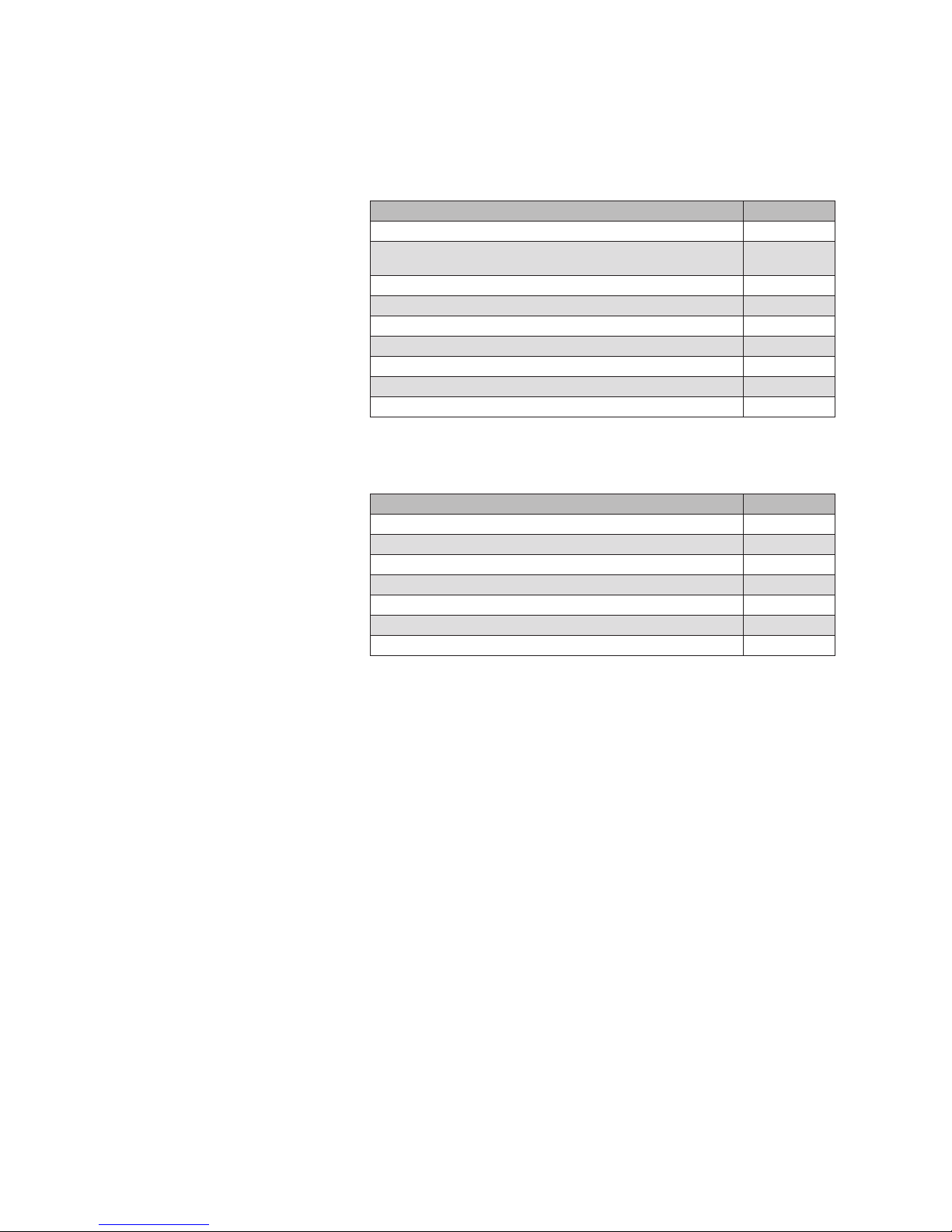
2.6 Additional documents
The following documents are available in addition to these instructions:
Document Number
WAREMA climatronic operating instructions 890033
Operating and installation instructions for
inside humidity/temperature sensor
816891
Operating and installation instructions for switch actuator 4/6M 816892
Operating and installation instructions for switch actuator 4/6M230 890031
Operating and installation instructions for dim actuator 2D 890185
Operating and installation instructions for the weather station 816894
Installation instructions for the sensor interface 816969
Installation instructions for the tableau interface 890006
WAREMA climatronic studio software manual 8164 67
2.7 Basic software
versions
These instructions were created on the basis of the software versions:
Product Version
WAREMA climatronic studio 1.2
Control panel 34404120
Weather station 24301102
Sensor humidity/temperature inside 23501100
Switch actuator 4M and 6M 23 712112
Switch actuator 4M230 and 6M230 23 712112
Dim actuator 2D 2 3712 113
Information on how to determine the software version of your control can be
found in Chapter 8.7 on page 113 of these instructions.
Safety instructions
890370_0•en•01.06.2009 We reserve the right to carry out improvements
13
3 Introduction
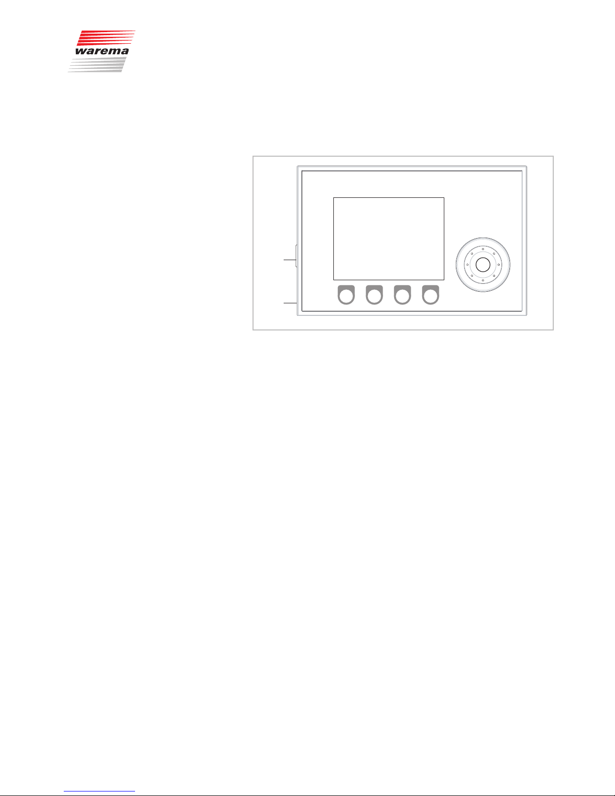
3.1 Operating elements
and interfaces
Õ
Œ
Ã
À
Fig. 1 The operating elements and interfaces of the WAREMA climatronic
Display:
The illuminated display informs you on everything you can view and set on
the WAREMA climatronic. For example, you can view the current measured
values of the outside brightness and outside temperature, the current time
and much more. The various elements of the display are explained in Chap-
ter 3.2.
2
Function wheel:
This wheel with detents can be turned (in both directions) to select and open
menus, channels, groups and scenes or current weather data and measuring
values in the display. When the wheel is pressed, a preselected menu item
can be opened, for example, or a modified value can be accepted.
3
Function buttons:
Depending on the information on the display, different processes can be
triggered with the function buttons. For example, you may jump to the main
menu, restore a preset value, cancel an input, and more.
4
SD card slot:
An SD card slot (see Fig. 1) is located on the left side of the control
panel. You can insert the SD card here to save the settings of your
WAREMA climatronic or to re-transfer stored settings or settings that were
changed on a PC (see also Chapter8.8 on page 114).
5
USB interface:
The USB interface is located on the same side. It serves to connect the
WAREMA climatronic with a PC. This allows the WAREMA climatronic to be
remote-controlled and operated entirely via a PC.
Introduction
890370_0•en•01.06.2009
We reserve the right to carry out improvements
14
WAREMA climatronic®
Installation Instructions
Furthermore, the optional WAREMA climatronic studio PC software al-
lows projects to be created or modified on the PC and transferred to the
WAREMA climatronic.
Information on this PC software is available in the manual (file: SoftwareHandbuch.pdf) on the enclosed CD-ROM. The installation instructions and
system requirements can be found in the Readme.rtf file.
The scope of delivery of the WAREMA climatronic includes a box with accessories containing, among other things, the CD-ROM, the matching USB cable
and the SD card.
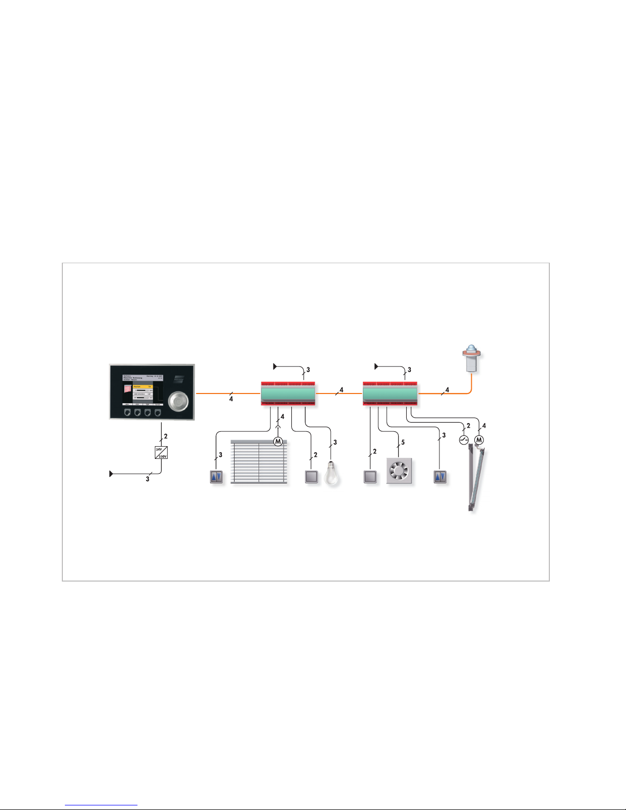
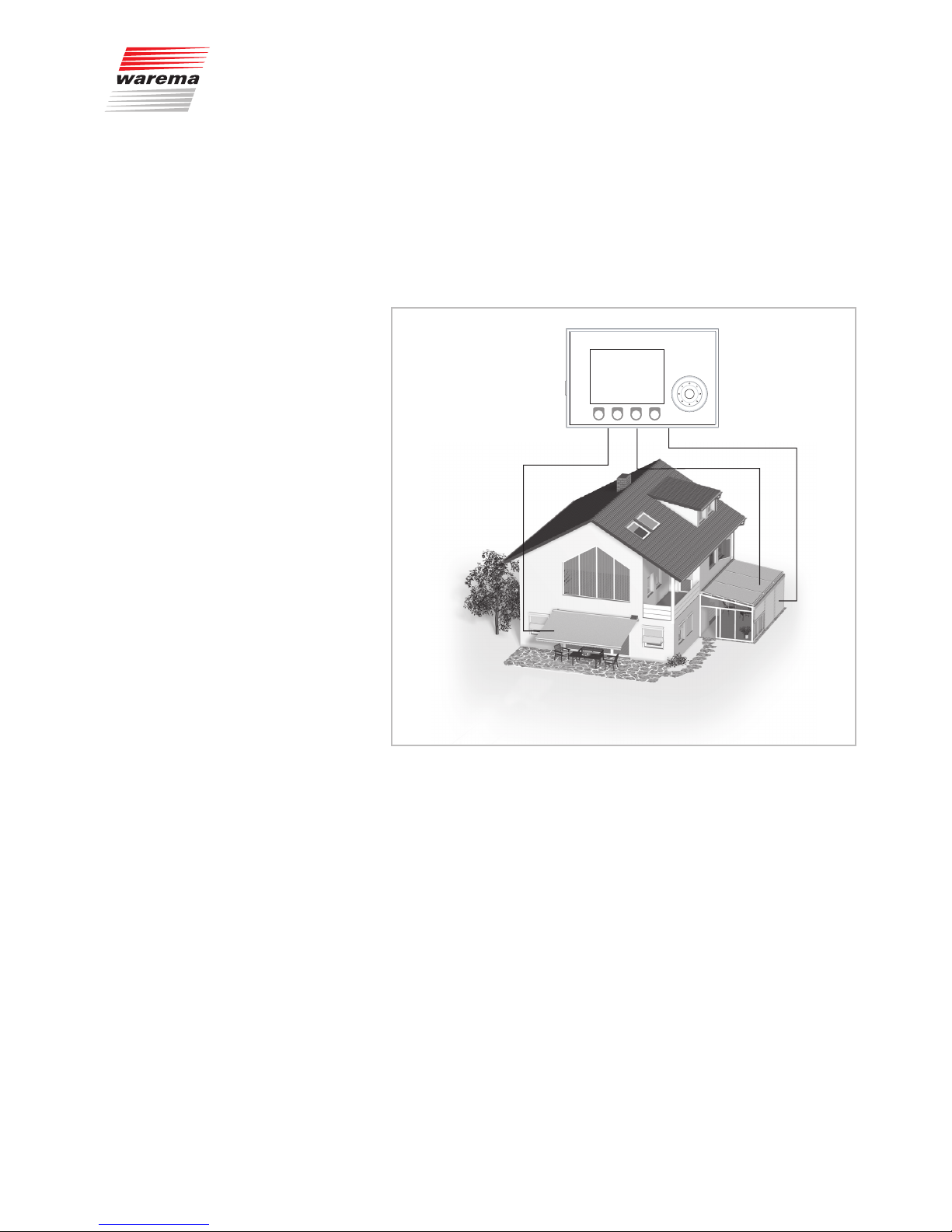
3.2 Principal structure of
a WAREMA climatronic
system
WAREMA climatronic
WAREMA climabus
Power
supply unit
Switch actuator
Switch actuator
Sun shading systemSunblind
pushbutton
Light
pushbutton
LightAdjustable fanPushbutton
for
adjustable fan
Window
pushbutton
Window
contact
Window
WAREMA climatronic
weather station
230V/50Hz
230V/50Hz
230V/50Hz
Fig. 2 Overview of the structure of a WAREMA climatronic system
The WAREMA climatronic is a complete solution to controlling all WAREMA
products and additional systems in a conservatory or in larger building complexes. Whatever the season, WAREMA climatronic will lower your energy
consumption and provide for a pleasant climate. This involves an interplay
between sun shading products, fans, windows, heating, air conditioning and
more in order to respond to weather-related influences from outside.
Introduction
890370_0•en•01.06.2009 We reserve the right to carry out improvements
15
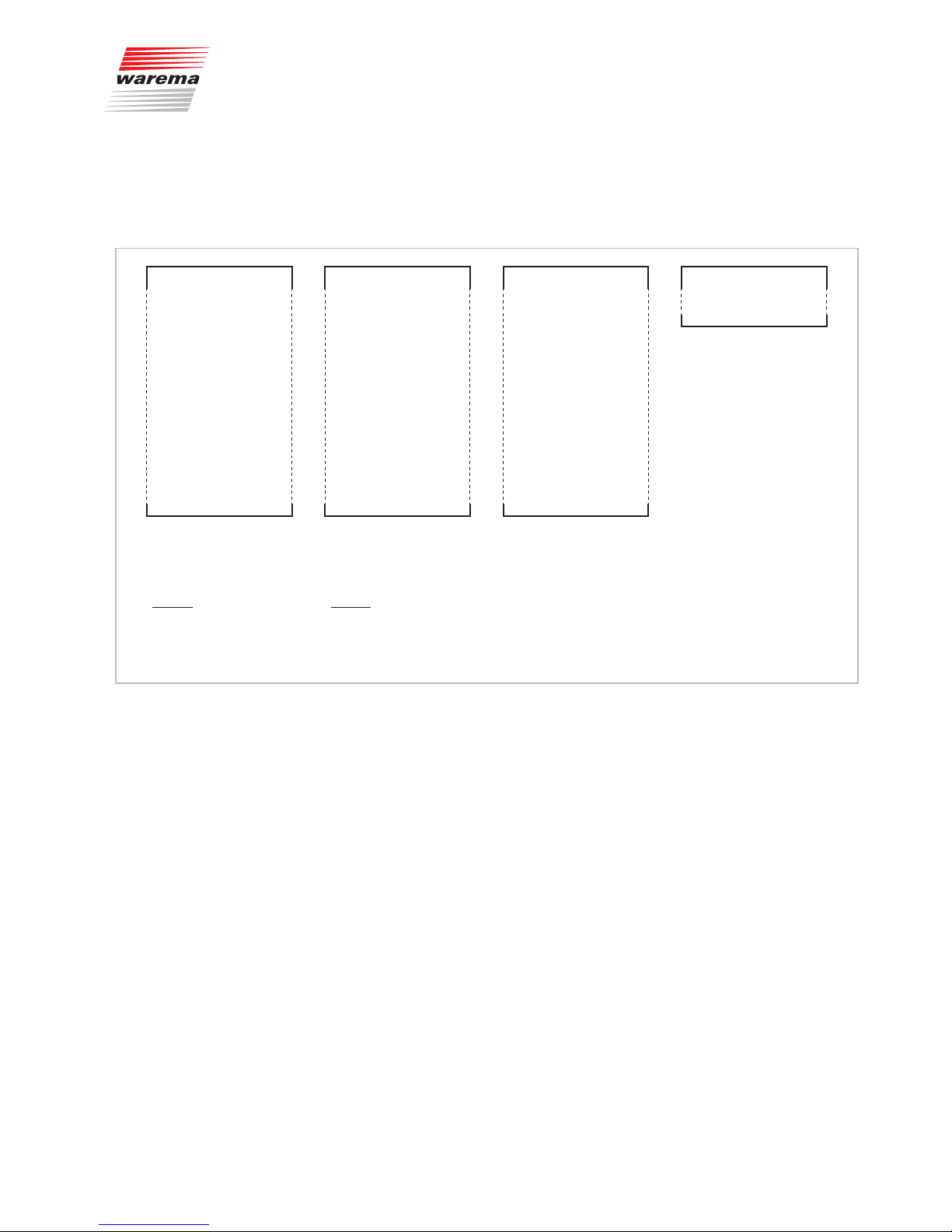
3.3 Concept
Before you install and start the WAREMA climatronic, this chapter will explain
the basic concept of the system and familiarise you with the many options
and the complex projects it can be used to realise.
Product 1 (external venetian
blind 1 south)
Channel 1 (external venetian
blind 1 south)
Group 1 (channel 1+2) Scene 1
Product 2 (external venetian
blind 2 south)
Product 3 (external venetian
blind 3 west)
Product 4 (external venetian
blind 4 west)
Product 5 (external venetian
blind 5 west)
Product 6 (external venetian
blind 6 east)
Product 7 (awning 1, roof)
Product 8 (light, living area)
Product 9 (external venetian
blind 7 north)
Product 10 (external venetian
blind 8 north)
.
.
.
.
Channel 2 (external venetian
blind 2 south)
Channel 3 (external venetian
blind 3 west)
Channel 4 (external venetian
blind 4+5 west)
Channel 5 (external venetian
blind 6 east)
Channel 6 (external venetian
blind 7+8 north)
Channel 7 (awning, roof)
Channel 8 (light, living area)
.
.
.
.
.
.
Group 2 (channels 3+4)
Group 3 (channels 1–6)
.
.
.
.
.
.
.
.
.
.
.
Scene 2
Scene 3
Scene 4
Product 1200 Channel 32 Group 32
Products are considered to be
all connected power consumers
(e.g.: sun shading product, light,
window, fan)
Any number of products can
be allocated to channels (e.g.:
channel 6, external venetian
blind north).
Any number of channels can
be organised into groups (e.g.:
group 3, all external venetian
blinds)
Any number of channels can be
organised into scenes; these
channels move to a position that
is previously learned in for a set
dwell time.
Setting of:
Contact allocation
Run times
Slat angle
Local pushbutton operating
mode
Setting of:
Product type
Safety functions (wind, ice)
Comfort functions
(precipitation, time, photo, dawn/
dusk, temperature, slat tracking)
Fig. 3 Properties of products, channels, groups and scenes
Introduction
890370_0•en•01.06.2009
We reserve the right to carry out improvements
16
WAREMA climatronic®
Installation Instructions
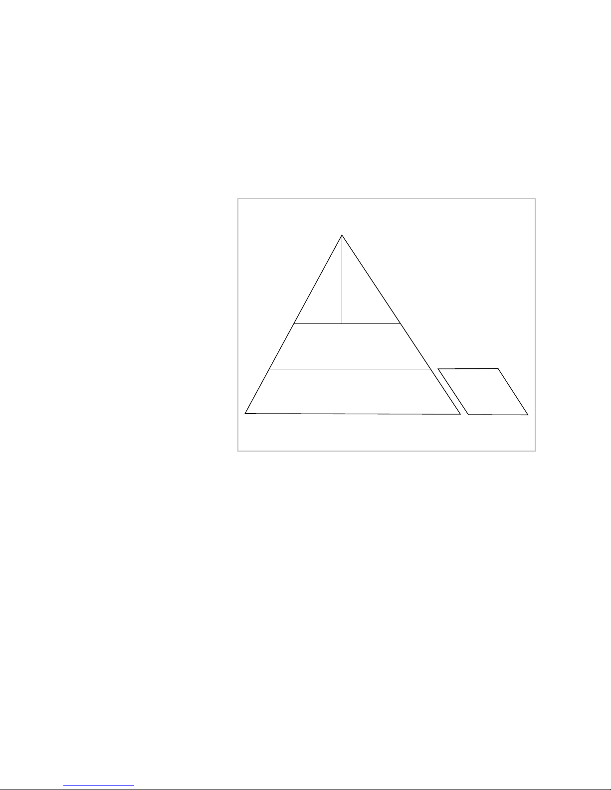
3.3.1 Pyramid diagram of
products, channels,
groups, scenes
The following pyramid diagram illustrates that the products controlled using
the WAREMA climatronic can (only) be combined to groups and scenes via
channels. An exception are local groups grouped via the terminals of available locking contacts, but which can only be operated together locally (detailed description: see Chapter 5.3 on page 34).
Products
Channels
Scenes
Groups
Local groups
Fig. 4 Pyramid diagram of WAREMA climatronic concept
Introduction
890370_0•en•01.06.2009 We reserve the right to carry out improvements
17
3.3.2 Channels, facades and
products
Because the term "facade" is occasionally misunderstood in regard to control
systems for sun shading products, this point shall be explained here in more
detail:
The WAREMA climatronic is equipped with more than 32 channels. Each
channel can access a single product (e.g. an awning) or several products of
the same type (e.g. roller shutters).
➊
➋
➌
Fig. 5 Example: channels of the WAREMA climatronic
Example In the example illustrated above, channel ➊ controls the awning on facade 1,
channel
➊
the conservatory awning on facade 2 and channel ➊ the external
venetian blinds of the conservatory on facade 2. This demonstrates that a
distinction according to building facades cannot be made in this example;
rather, the individual channels are referred to here.
Example Another example: The WAREMA climatronic controls all roller shutters on the
west facade with channel 1, all roller shutters on the south facade with channel 2 and all roller shutters on the east facade with channel 3. Because each
facade is controlled separately here, the term "facade" could be used instead
of "channel" in this example.
NOTE In these instructions we only use the term "Channel".
Introduction

890370_0•en•01.06.2009
We reserve the right to carry out improvements
18
WAREMA climatronic®
Installation Instructions
The WAREMA climatronic always logically controls products through channels. The following product types can presently be activated using the
WAREMA climatronic:
Articulated arm awning Light
Conservatory awning Light, dimmable (external)
External venetian blind Fault alarm contact
Roller shutter Internal roller blind
Pleated blind Vertical awning
Venetian blind Facade awning
Window Drop arm awning
Fan, fan valve Markisolette
Fan 3 steps Fan, infinitely variable (external) with fan valve
Fan, infinitely variable (external) Fan 6/12 V with fan valve
Air conditioner Fan, infinitely variable with fan valve
Heater Light, dimmable
A product is connected directly to the outputs of a switch actuator of the
WAREMA climatronic. It requires one to three switching outputs; for example,
sun shading products require two switching outputs for raising and lowering,
a light requires only one switching output for switch-on and switch-off.
3.3.3 Groups
If you want to manually activate several channels together, they can be combined into a group. You can then, for example, raise or lower the conservatory awning and the external venetian blind of a conservatory together.
Up to 32 channels can be allocated to one group.
NOTE The group adopts the product properties of the first allocated channel; if
this is a roller shutter, for example, then the operating behaviour of the group
corresponds to that of a roller shutter even if other slat products, lights or climate control products belong to this group.
Of course, channels with identical products can also be combined to a
group. For example, if you have created a channel 1 for the roller shutters
of each room, then all roller shutters of the building can be combined to a
group and moved at the same time.
A maximum of 32 groups can be created.
3.3.4 Scenes
A scenario (e.g. "roller shutters up, lights off, heating off" when leaving the
flat) can be stored ("learned") in a scene and be called at a later time.
One or more channels are allocated to the scene for this purpose and set
as desired. After the scene has been stored, this scenario can be recalled at
any time by selecting the scene.
Introduction

890370_0•en•01.06.2009 We reserve the right to carry out improvements
19
4 Installation
CAUTION
Dangerous situations and malfunctions are possible. The control and its
auxiliary components may only be operated when installed and at the
specified installation locations. Malfunctions of the system or dangerous
situations may occur if this is neglected. In every case, this will render any
guarantee or warranty null and void.
4.1 Accessory box
The scope of delivery of the WAREMA climatronic includes a box with accessories. It contains the following parts for assembly, installation and commissioning:
Installation instructions
Operating instructions
Base plate for the control panel with mounting screw and nut
4 screws and anchors for wall-mounting
USB cable to connect the control panel to a PC
Software CD with WAREMA climatronic studio
SD card for saving WAREMA climatronic settings
Magnet for identification of the weather station
Pouch with terminating resistor and terminal clamp
Installation
890370_0•en•01.06.2009
We reserve the right to carry out improvements
20
WAREMA climatronic®
Installation Instructions
4.2 Procedure
Follow the points below in the order given:
First determine where the individual components are to be installed. Refer to
the specifications in this chapter and in the sensor and switch actuator data
sheets.
NOTE The last page of the switch actuator instructions contains tables for noting
down the terminal assignments. This is absolutely essential for the future
software-specific allocation on the control panel of the WAREMA climatronic.
Also affix an ID sticker of the actuator on the field provided for this purpose
and note down the installation location and any additional information on the
device, if necessary.
Do not use lines of a larger cross-section than specified.
Then determine which cables are required to connect the components with
one another. To do this, please refer to the "Wiring diagrams" chapter. Be
aware that terminal sets of multi-pole products must be connected to the
same terminal block of a switch actuator and not to two separate ones. Lay
the required lines.
Preferably use cable ducts to route the motor lines.
WARNING
Electrical equipment must be installed in an easily accessible location
(VDE0100).
Install and wire the individual components.
CAUTION
When wiring bus terminals that have already been plugged in, only needlenosed pliers may be used to pull them off again to prevent damage to the
bus terminals or the contact pins.
Check the wiring before switching on the power supply to the control.
Then commission the unit. Only then will the control be ready to use. The
steps required for commissioning are explained in detail in these instructions.
Check the correct running direction of the sun shading product by operating
the "Up" and "Down" buttons on the control.
Check that the connected sensors are functioning properly.
Check whether the sun shading products are moved to a safe position when
a wind alarm is triggered.
Activate the precipitation control and check whether the control function re-
sponds to precipitation (moisten the sensor surface with water).
Then adjust the functioning of the system to the ambient conditions and spe-
cial requirements.
Installation
890370_0•en•01.06.2009 We reserve the right to carry out improvements
21
4.3 Planning the network
structure
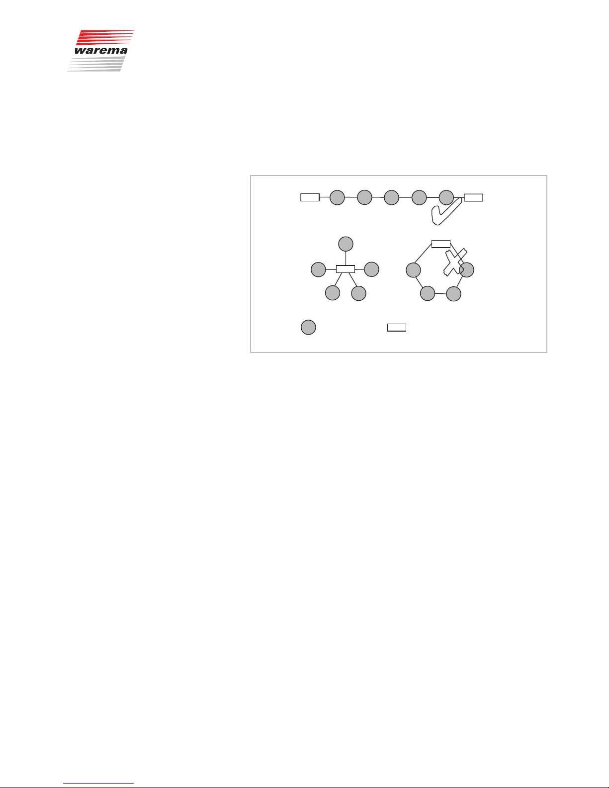
All components of the control communicate with each other via an RS 485
bus system. The structure of the network resembles a line structure. Careful
planning of the network prior to installation saves you elaborate and timeconsuming adjustment work.
= Components
= Terminating resistance
✔
✘
✘
Fig. 6 Bus topology: Do not use start or ring circuits.
Please observe the following items regarding the network structure:
NOTE The control panel should constitute the starting point of the network and the
weather station the terminating point since these two units are equipped with
a factory-activated terminating resistor of 120Ω.
If this arrangement is not possible and a switch actuator or the humidity/tem-
perature sensor constitutes the terminating or starting point of the network,
the starting and terminating point of the bus lines must be concluded with
120Ω. The accessory box includes a suitable bus terminal with an integrated
terminating resistor as well as a single resistor as a spare part.
If the weather station or the control panel is not positioned at the starting
or terminating point of the line, the installed terminating resistor must be removed. On the weather station, it is removed by taking off or switching the
connector (see Fig. 22 on page 43) and on the control panel by using a bus
terminal without an integrated resistor.
The X6(A) and X6(B) bus terminals are used to connect the bus lines. Note
the colour coding of the terminals: do not switch the terminals by mistake.
A maximum of 200 actuators, 3 weather stations and 2 humidity/temperature
sensors may be used in one system.
In case of system malfunction, check whether the bus line has been flaw-
lessly terminated with 120 Ω at both ends.
Also check whether the bus line is correctly connected. The correct polarity
must be adhered to (red and black).
NOTE Observe also Fig. 7 regarding the network arrangement.
Installation
890370_0•en•01.06.2009
We reserve the right to carry out improvements
22
WAREMA climatronic®
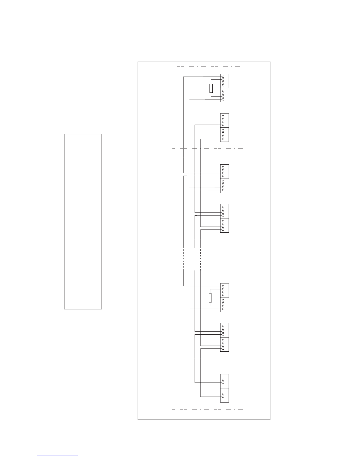
Installation Instructions
R
- +
Output 24V / 2,5A
Power supply unit Control panelAdditional
devices
Switch actuator Weather station
X5
0V 24V
Supply
ws
ge
X6
A B
RS 485
sw
rt
X5
0V 24V
Supply
ws
ge
X6
A B
RS 485
sw
rt
R
X5
0V 24V
Supply
ws
ge
X6
A B
RS 485
sw
rt
Fig. 7 Basic network structure
CAUTION
The network must be set up according to a line structure with
a 120 Ω terminating resistor on both ends. Star circuits or ring
circuits are not permitted; see Chapter 4.3.
Installation

890370_0•en•01.06.2009 We reserve the right to carry out improvements
23
4.3.1 The serial number
Each device that can be integrated into the network has a uniquely assigned
number, the serial number. The number is included and for switch actuators it
is located in duplicate under the plastic cover; for humidity/temperature sensors inside the enclosure cover, for weather stations on the back under the
cable channel cover and for control panels on the back of the enclosure.
Pull off a sticker and affix it to the field provided for this purpose on the last
page of the instructions of the network device.
Note down the installation location and any additional information that may
be necessary.
Keep all operating and installation instructions in a central location.
This measure allows for the unambiguous identification of network devices
during future integration.
Alternatively, you can also use the following table to affix the labels:
Device type
(affix label here)
Installation location
Installation
890370_0•en•01.06.2009
We reserve the right to carry out improvements
24
WAREMA climatronic®
Installation Instructions
Device type
(affix label here)
Installation location
Installation
890370_0•en•01.06.2009 We reserve the right to carry out improvements
25
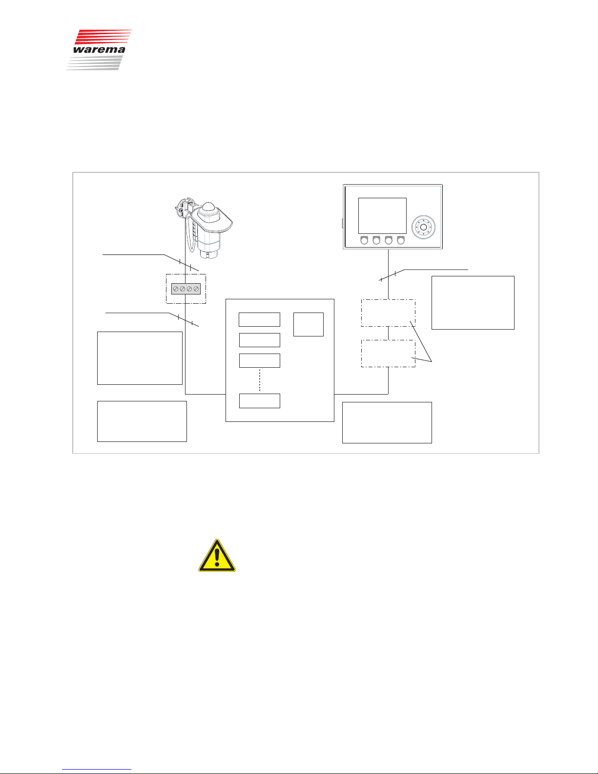
4.3.2 Sizing the power supply
If the actuators (max. 20 per power supply unit) are accommodated in an
equipment cabinet and the weather station, the control panel and up to two
inside temperature and humidity sensors are arranged according to the schematic diagram, you can simply take the maximum cable lengths from the following schematic diagram:
Equipment cabinet
Power
supply unit
24V/2,5A
Actuator 1
Actuator 2
Actuator 3
Actuator 20
Temperature
and humidity sensor 1
Temperature
and humidity sensor 2
Control panel
JY(St)Y 2x2x0,8mm ø
The maximum total line
length between the
control panel and the
equipment cabinet is
200 m!
Weather station
4xAWG 26C UL black
The maximum line length
between the weather
station and the
equipment cabinet
is 150 m.
When using 20 actuators or
more, a separate power
supply unit is required
per 20 devices!
Junction box
JY(St)Y 2x2x0,8mm ø
Optional
The network must have a
line structure. A star or ring
circuit is not permitted!
Fig. 8 Schematic diagram of the standard configuration
The power supply unit required to supply the bus devices delivers an output
current of max. 2.5 A and supplies the network stations with 24 VDC; see
Fig. 7.
CAUTION
However, if the actuators are installed distributed over several rooms, the
maximum permitted cable lengths (total length of line) must be calculated
according to the following formula (see further below) considering the total
current required.
Installation
890370_0•en•01.06.2009
We reserve the right to carry out improvements
26
WAREMA climatronic®
Installation Instructions
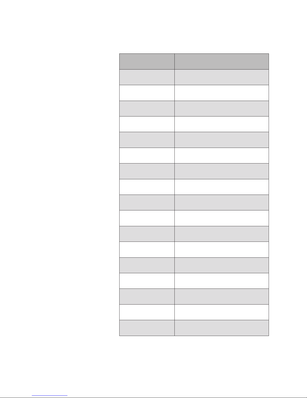
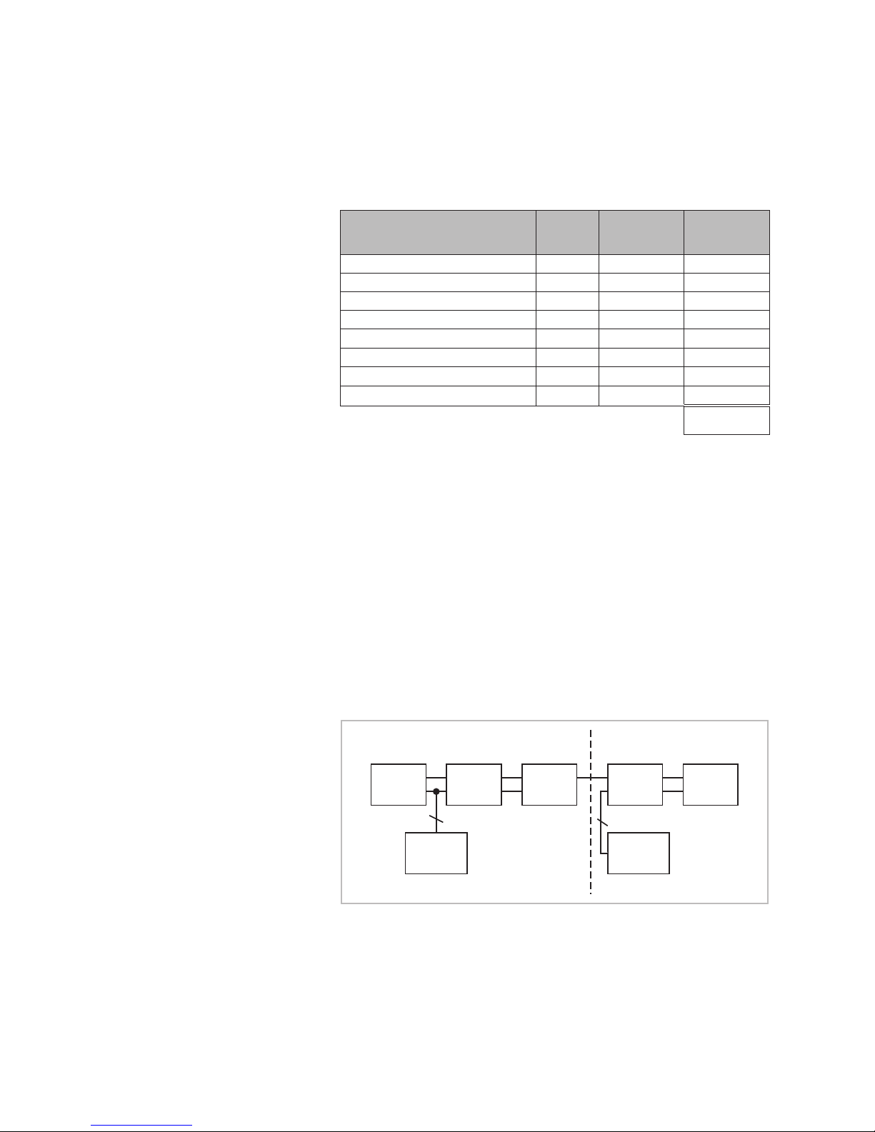
Depending on the number of stations, additional power supply units may be
required. Determine the total power requirements according to the following
table:
Device
Number
(piece)
Current con-
sumption
(mA)
Total current
Control panel 1 17 0 170
Weather station 250
Inside humidity/temperature sensor 50
Switch actuator 4M/6M 90
Switch actuator 4M230/6M230
—
Dim actuator 2D 50
Sensor interface
Tableau interface
—
Total:
Note the following regarding the table:
The 4M230/6M230 switch actuators are supplied directly via the 230V
mains and do not need to be taken into consideration here.
The current consumption of the sensor interface depends on the number and
type of connected sensors. Determine the current consumption in advance
with the sensors connected or provide a separate power supply unit for the
sensor interface. Information on this can be found in the sensor interface installation instructions.
The tableau interface must be supplied via a separate power supply unit.
Information on this can be found in the tableau interface installation instructions.
Do not connect the power supply units in parallel. Note the following block
diagram:
Control
panel
Actuator
1
Actuator
2
Actuator
3
Weather-
station
Power
supply unit
1
Power
supply unit
2
2
2
Fig. 9 Block diagram: several power supply units
If a total current of 2.5 A is reached by adding a node (= network device) to
the line, no additional network devices may be connected after this. In this
case, provide an additional power supply unit for a separate section of the
line.
Installation
890370_0•en•01.06.2009 We reserve the right to carry out improvements
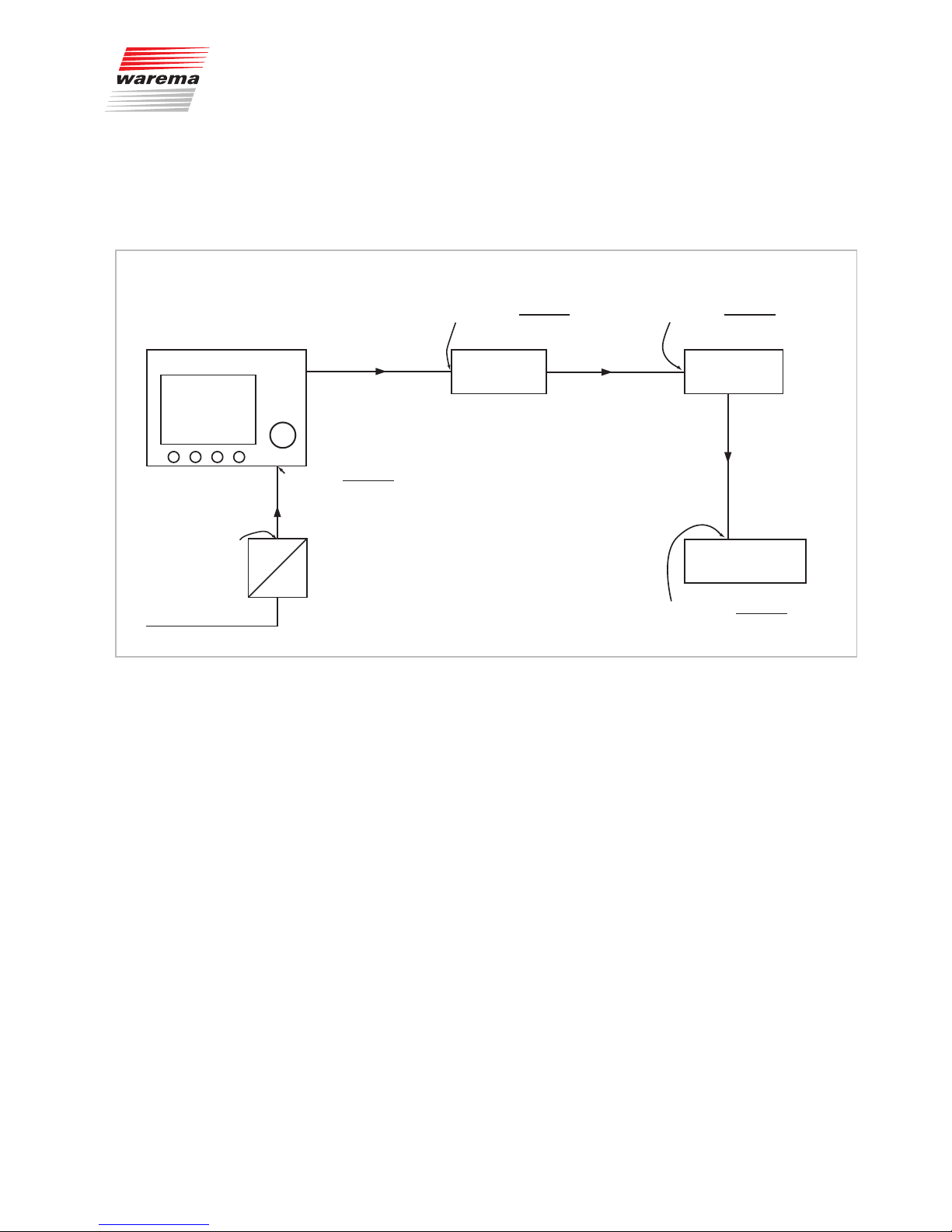
27
The voltage may not drop below 20 V at any point, not even at the last de-
vice of the bus. (UA<4V)
Also include the length of the line (supply line) or the length of the line sec-
tion in your calculations.
Control panel 170 mA 6M-Actuator 1
90 mA
6M-Actuator 2
90 mA
Weather station
250 mA
L2=20 m
L4=20 m
L3=20 m
L1=10 m
AC
230 V
24 V
DC
U=24 V
U=24 V–
2·L1·I
L1
κ·A
( )
=23,6 V
I
L1
=(170+90+90+250)mA=
600 mA
IL3=(90+250)mA=
340 mA
I
L4
=250 mA
IL2=(90+90+250)mA=
430 mA
U=23,6 V–
2·L2·I
L2
κ·A
( )
=23 V
U=23 V–
2·L3·I
L3
κ·A
( )
=22,5 V
U=22,5 V–
2·L4·I
L4
κ·A
( )
=22,1 V
Fig. 10 Voltage drops and partial currents
The following formula applies to the voltage drop UA on the line:
2 · I
LA
· L
UA = ------------------- κ · A
U
A
= Voltage drop on the 24V supply line
L = Single length of line inm
κ = kappa (conductivity, use the value56 for copper)
A = Cross-section of the supply line in mm
2
ILA = Current in the line section inA
Preferably, position the power supply unit in the centre of the line or line sec-
tion to minimise the voltage drops. The voltage drop may not be greater than
4V from the power supply unit to the end of the line or line section.
Installation

890370_0•en•01.06.2009
We reserve the right to carry out improvements
28
WAREMA climatronic®
Installation Instructions
4.3.3 Use of repeaters and hubs
Note the following rules:
When using 100 actuators or more, one repeater is required per 100 de-
vices.
One repeater is required after every 1200m of line length.
A maximum of 200actuators, 3weather stations and 2humidity/temperature
sensors may be used in one system.
For installation information for repeaters and hubs, please refer to the instructions included with these devices.
4.3.4 Network cables
Use only high-grade twisted-pair network cables with a characteristic wave
impedance of 120Ω. We recommend:
JY(St)Y2x2x0.8mmø or JY(St)Y4x2x0.8mmø
YCYM2x2x0.8mmø or YCYM4x2x0.8mmø (Siemens)
Unitronic bus line 2x2x0.8mm ø or 4x2x0.8mmø (LAPP)
UV-resistant cables must be used for outdoor installation (e.g. to connect the
weather station). We recommend:
8xAWG26CULblack
4.4 Installing the control
panel
Because of its flat design, the control panel is intended to be surface-mounted. A flush-mounted box behind it is required for the wiring.
Choose an installation height that permits convenient reading of the display
(recommended: bottom edge of the device approx. 1.45 m above the top
surface of the flooring).
When choosing the installation location, also ensure that the left enclosure
edge is sufficiently far from a wall, cabinet, picture or other obstacle to allow
for the convenient insertion and removal of the SD card and USB cable (recommended: at least 12-15 cm).
NOTE A temperature sensor is integrated in the control panel itself. Therefore, to
prevent erroneous readings, do not install the control panel where a heat
source may influence the measurements (sunlight, radiator, outside wall).
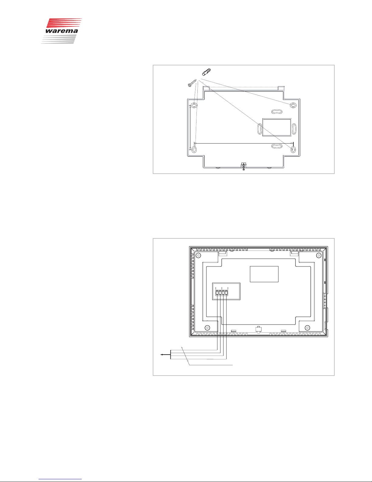
Mount the base plate on a flush-mounted switch box using suitable fasteners.
Align the base plate exactly level with the help of the elongated holes.
Countersink the 4 countersunk screws included with the delivery to allow the
control panel to fully engage.
Installation
890370_0•en•01.06.2009 We reserve the right to carry out improvements
29
170 mm
76 mm
4x
Fig. 11 Installation of the base plate
NOTE Ensure that the mounting surface is not uneven. The base plate may oth-
erwise become warped and the control panel would not be able to engage
properly.
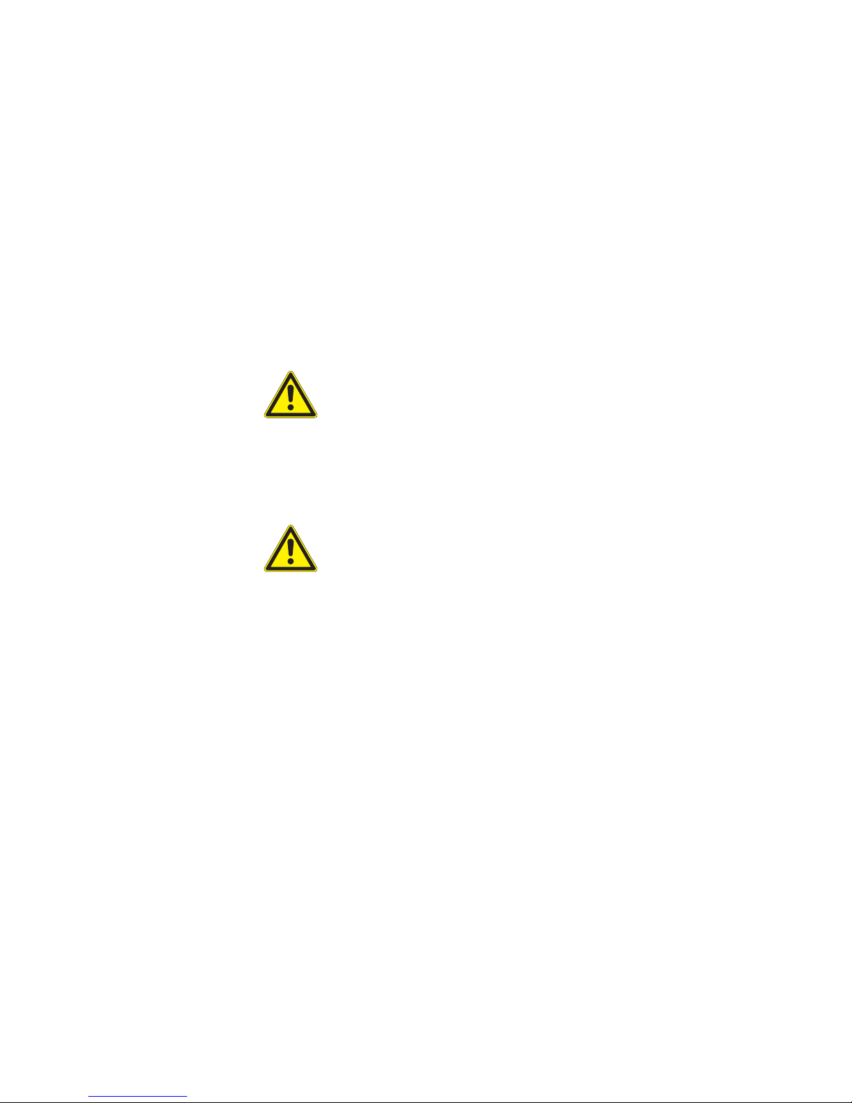
Connect the individual wires according to the following diagram; observe the
colours of the terminals.
X5
0V A B
24V
X6
wt yl
bk
rd
JY(St)Y 2x2x0,8mm ø
wt
yl
bk
rd
to additonal
components
RS 485
Fig. 12 Control panel wiring diagram
Installation
890370_0•en•01.06.2009
We reserve the right to carry out improvements
30
WAREMA climatronic®
Installation Instructions
Attach the control panel to the base plate by hooking it on the top edge of
the base plate and then pushing against the bottom edge until it snaps into
place.
Fix the control panel with the supplied screw, which is turned into the centre
of the bottom edge.
The control panel is now securely mounted to the wall.
4.5 Installing the switch
actuators
The switch actuators are available as a DIN rail-mounted device (REG) or in
a surface-mounted or flush-mounted box. The devices must be installed in
a dry and readily accessible location. Never install them outdoors or where
they are subjected to direct sunlight.
CAUTION
The permanently routed installation must be equipped with a disconnecting
and isolating switch to separate the switch actuators from the supply voltage
(switch according to EN 60335-1, Section 25.3, e.g. circuit breaker).
Please observe the cable types recommended in the wiring diagrams.
DIN rail-mounted devices must be mounted on a symmetrical DIN rail
(35mm as per DIN EN 50022).
CAUTION
The minimum clearance between the terminals and another object equals
10 mm in the rail-mounted variant. When switch actuators are properly
mounted in the surface-mounted or flush-mounted housing type, no minimum
clearances need to be observed between the housing and the surrounding
objects.
Please note the associated installation and operating instructions before
installing the flush-mounted, surface-mounted or rail-mounted version of the
actuators.
Installation
 Loading...