

890214_b•en•07.11.2011
We reserve the right to carry out improvements
1
Operating and installation instructions
WAREMA Timer
Keep for future use!
Valid from 1st December 2011
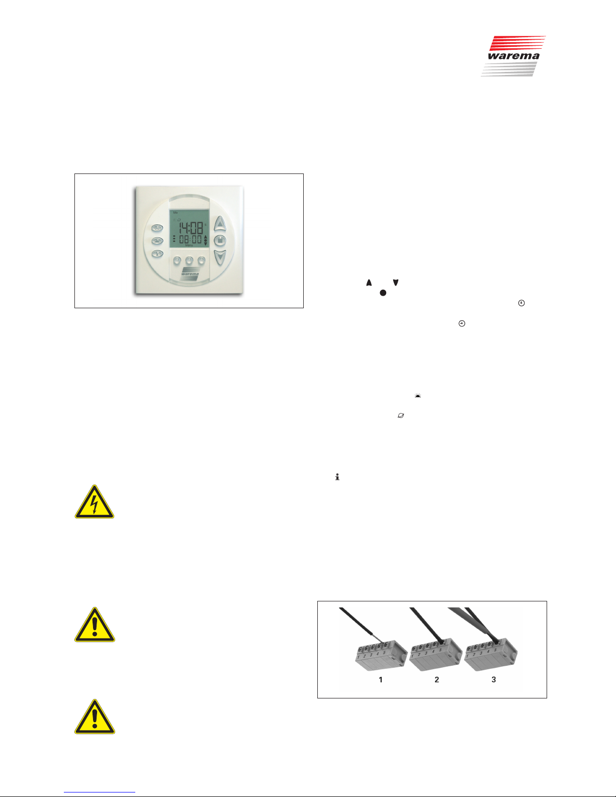
General
Fig. 1 WAREMA Timer
The WAREMA Timer is a time switch with floating output
specifically for actuating roller shutters. These can be
controlled automatically using an integrated time switch
control and a dawn/dusk control. The dawn/dusk control
using astronomical data (date and location) to calculate
the time of dusk.
Intended use
The device was developed to control sun shading systems. The approval of the manufacturer must be obtained
for uses outside of the purposes listed in these instructions.
Safety information
WARNING
The electrical installation must be performed by a certified electrician in accordance with the electrical installation regulations published by the Association of
German Electrical Engineers (VDE 0100)
or the standards and regulations of the
country in which the device is being installed. The specialist must observe the
installation instructions included with
the electrical device.
WARNING
If hazard-free operation cannot be assumed, the device may not be started or
must be deactivated. This assumption is
justified
if the housing or the supply lines show
signs of damage,
the device is no longer working
WARNING
It is important to comply with the following points of instruction in the interest of
personal safety!
■ Children may not play with the operating elements of the
control unit!
■ Make sure that no persons or objects are in the range of
movement of the driven parts (blinds, window, etc.!
■ Disconnect the product from the supply voltage if clean-
ing or other maintenance work must be performed!
■
The device may only be used to control drives where the
movement of the product (roller shutter) cannot cause
any injury.
Function
The buttons and can be used to control your blind
directly and the button or the button for the opposite direction is used to pause the movement. The button can
be used to switch the time switch control on and off. When
the time switch control is active, the character appears
on the display. You can set an upward movement and a
downward movement for each day. With the automated
random function activated, the switch times programmed
via the time switch control are changed randomly by + / 30 min (a dice is displayed on the display). This creates
the impression that the roller shutter is being moved up
and down manually. The button can be used to switch
the dawn/dusk control on and off. When the dawn/dusk
control is active, the character appears on the display.
The dawn/dusk times calculated can still be changed by
+ / - 60 min. With the dawn/dusk control switched on, a
down movement command is initiated in the evening at
the time calculated. In the morning, the sun protection can
either be raised via the time switch control or manually.
The button display the last cause and the direction of
movement when activated.
Installation
The device is mounted in a deep flush-fitted wall box. This
makes connecting the terminals easier.
■ Mount the device only in inside areas! The device is
not suitable for use in damp interiors.
■ The electrical connection of the product is done ac-
cording to the wiring diagram given below.
As an option, the device can also be mounted in a
surface-mounted box.
Fig. 2 Connecting and disconnecting the line connections
890214_b•en•07.11.2011We reserve the right to carry out improvements
2
After removing the insulation on the wires, these are
pressed into the terminal (1), until the insulation on the
wires enters the terminal and the line is securely held
in the terminal (2). To disconnect the wire, the relevant
unlock button needs to be pressed in using a screwdriver
as far as it will go, and the wire then removed from the
terminal (3).
4x
A
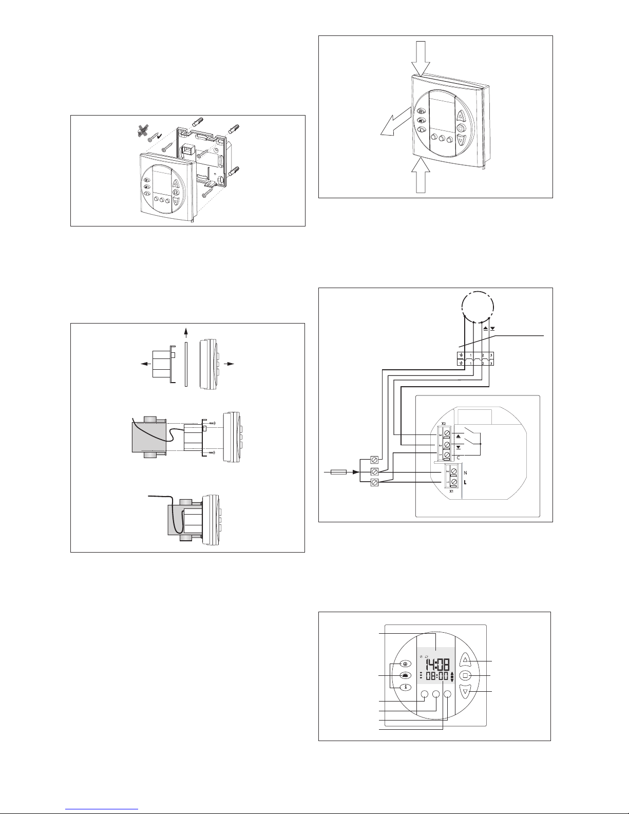
Fig. 3 Wall mounting
■ Use appropriate anchors and screws for mounting.
■ The screw heads must be screwed in flush to the
mounting plate otherwise the control panel will not fit
correctly.
■ If preferred, the device can also be screwed onto
the flush-fitted wall box.
Note: Screws and anchors are not included.
Power unit
Control panel
Fig. 4 Installation
■ Before mounting, the transport protection (cardboard
between the control panel and the power unit) must be
removed! Do not fit the control panel onto the power
unit in an unassembled state!
■ Connect the wires in accordance with the wiring dia-
gram (connecting the spring terminals, see fig.3). Fitted on the outside using casing screws or screws and
anchors.
■ Fit the control panel.
Disassembly
■ For disassembly, grip the time switch on points 1 and 2.
■ Then remove the device from the wall holder in
direction 3. Please refer to the following diagrams in this
regard:
1
2
3
Fig. 5 Disassembly
Electrical installation
An on-site overload current disconnecting and isolating
switch to switch off the entire system must be provided.
The device meets the EMC guidelines for use in residential
and commercial areas.
L
C
X1
X2
1
2
N
1
2
3
1
2
3
1
2
3
PE
N
M 1~
PE
N
L
Plug-and-socket connection
H05RR - F4G0.75mm2 black
230 V AC 50 Hz / 6 A
power cable
from customer
Fig. 6 Wiring diagram
Commissioning
The device is operational after the installation has been
completed and the supply voltage applied.
Operation in display mode
Mo
Menu
S
7
8
6
1
2
3
4
5
9
Fig. 7 Operating and display elements

3
890214_b•en•07.11.2011 We reserve the right to carry out improvements
You are in display mode when the time is displayed on the
display (1) and the colon between the hour and minutes
display is flashing. The control buttons have the following
functions in display mode:
2 "Up" button raises the sun protection.
3 "Stop" button stops a move command.
4 "Down" button lowers the sun protection.
5 Function buttons:
button : Switches the time switch control on and off
button : Switches the dawn/dusk control on and off
button : Display of the last cause
6, 7 "Back", "Forwards" button ( ): The menu options
can be changed in setting mode using these buttons.
No function in display mode.
8 Button [Me nu]: This button takes you into setting mode.
Once you are in this mode, the operating buttons have
different functions.
9 Display of the next switch time when another later time
has been set for the same day
Settings
To change the settings, you need to change to setting
mode; to do this press the
[Menu] button. The menu num-
ber is displayed next to the text (Set). The
(previous
menu) and (next menu) buttons can be used to display
the menus in sequence. Values that can be changed are
always displayed flashing. You can then change the value
using the
buttons or . If you want to save your settings,
press the button and your settings will stop flashing. If
you want to exit setting mode, press the [Menu] button. The
time switch will then return to display mode.
Setting the time switch control
For the time switch control settings, the preselection of
the weekday is very important. Here you specify whether
the setting is changed for a specific day or whether the
entire weekly program is changed. First you need to select
in menu 01 the day(s) for which you want to make the
setting. Select using the
button or button (the days
set will be flashing) and confirm with the button (display
stops flashing). Set the hours in menu 02 and the minutes
in menu 03, for the time at which the curtain is to be lowered, and confirm each selection using the button. The
time at which the curtain is to be raised is set in menus
04 and 05. If you do not want to set up and down times,
set - -. To carry out settings for the remaining days, start
back at menu 01.If you have selected a block consisting of
multiple days, and u:u is displayed when setting the times,
this indicates that different times are currently stored for
those days. The random function is switched on and off for
all times in the time switch control in menu 06.
With (on), the set times are changed each day
by +x/ - 30 min.
Setting the current time / date
Set the current time and date in menus 07 to 12. (On) in
menu 9 goes to the automatic conversion of the clock for
summer and winter times.
Setting the runtime
The runtime after which the curtain stops is set in menu 13
(max. 300 sec).
Setting the dawn/dusk control
In menu 15 you need to enter your location for the dawn/
dusk control using a three-digit code which the WAREMA
Timer uses to calculate the times for dawn/dusk. For Germany, the first digit is 0, and the other digits are the first
two digits of your postal code (e.g.: Würzburg PLZ 97070
→ 097). For other countries, the number can be found in
the astro list. To do this, find the town closest to your location. The dawn/dusk control delay can be set on menu 16.
Here you can enter by how many minutes earlier or later
than the sunset time calculated you want to lower your curtain (+ / - 60 min). For example, if you set the value "-30",
the curtain will be lowered 30 min before sunset.
Loading the factory settings
You can load the factory settings in menu 17. All parameters are overwritten with the factory settings following
confirmation.
Overview of the setting menus
Menu Function Possible
settings
Factory
setting
01 Time switch control: Select
weekday, weekend, working
week or calendar week
Weekday,
weekend,
working week
or calendar
week
---
02 Time switch control: Lower sun
protection switching time
Hour 22
03 Time switch control: Lower sun
protection switching time
Minute 00
04 Time switch control: Raise sun
protection switching time
Hour 8
05 Time switch control: Raise sun
protection switching time
Minute 00
06 Time switch control: Random up
and down switching times
ON/OFF OFF
07 Set clock Hours
08 Set clock Minutes
09 Activate/deactivate automatic
summer/winter time switching
ON/OFF ON
10 Set calendar day 1 - 31 1
11 Set month 1 - 12 1
12 Set year 2001 - 2099 2007
13 Run time 0 – 300 sec 60 sec
14 Software version --- --15 Location for dawn/dusk control --- 060
16 Dawn/dusk control delay +/- 60 min --17 Load factory settings cLr ---
Maintenance
There are no parts within the device that require
maintenance.

890214_b•en•07.11.2011We reserve the right to carry out improvements
4
Astro list
Code Country Tow n
100 Afghanistan Kabul
101 Egypt Cairo
102 Algeria Algiers
103 Argentina Buenos Aires
104 Ethiopia Addis Abeba
105 Australia Adelaide
106 Australia Brisbane
107 Australia Canberra
108 Australia Darwin
109 Australia Melbourne
110 Australia Perth
111 Australia Sydney
112 Bahamas Nassau
113 Bangladesh Dhaka
114 Belgium Maastricht
115 Belgium Brussels
116 Bolivia La Paz
117 Brazil Rio de Janeiro
118 Brazil Sao Paulo
119 Bulgaria Sofia
120 Chile Santiago
121 China Peking
122 China Shanghai
123 Cuba Havanna
124 Denmark Copenhagen
125 Dominican
Republic
Santa
Domingo
126 El Salvador San Salvador
127 England London
128 Estonia Tallinn
129 Fiji Islands Suva
130 Finland Helsinki
131 France Paris
132 France Nice
133 France Lyon
134 Greece Athens
135 Guatemala Guatemala
136 Honduras Tegucigalpa
137 Hong Kong
(SAR)
Hong Kong
138 India Calcutta
139 India Delhi
140 Indonesia Jakarta
141 Iraq Baghdad
142
Iran Tehran
143 Ireland Belfast
144 Ireland Dublin
145 Iceland Reykjavik
146 Israel Jerusalem
147 Israel Tel Aviv
148 Italy Rome
149 Italy Naples
150 Italy Genoa
151 Italy Florence
152 Jamaica Kingston
153 Japan Tokyo
154 Jordan Amman
155 Canada Edmonton
156 Canada Halifax
157 Canada Montreal
158 Canada Ottawa
159 Canada Toronto
160 Canada Vancouver
161 Canada Winnipeg
162 Kazakhstan Astana
163 Ken ya Nairobi
164 Columbia Bogota
165 Croatia Zagreb
166 Kuwait Kuwait
167 Latvia Riga
168 Lithuania Vilnius
169 Lebanon Beirut
170 Luxemburg Luxemburg
171 Malaysia Kuala Lumpur
172 Morocco Casablanca
173 Mexico City Mexico
Liability
Failure to comply with the product information in these
instructions and use of the device in a manner that contravenes its intended use and purpose may result in the
manufacture refusing to honour warranty claims for product damage. In this case, liability for consequential harm
to persons or damage to property will also be excluded.
Follow also the instructions in the operating manual of
your sun shading system. The automatic or manual operation of the sun shading system when iced over as well as
using the sun shading system during severe weather may
cause damages and must be prevented by the user by
taking suitable precautions.
Disposal
After its use, the device must be disposed of according to
legal regulations or returned to your local recycling centre!
Technical data
WAREMA Timer Min. typ. Max. Unit
Power supply 230 V AC / 50 Hz
Operating voltage 207 230 253 V AC
Power consumption 1 2 VA
Floating output
Switching capacity at
230 V AC / cos ϕ 0.6
700 VA
Switching capacity at
24 V DC
72 W
Enclosure
Dimensions in mm
(W x H x D)
80 x 80 x 54
Degree of protection type / safety class
Degree of protection IP 30
Safety class II
Test standards
DIN EN60730-1:2002
DIN EN61000-6-2:2002
DIN EN61000-6-3:2002
DIN EN300220-3:2001
EN301489-3:2001
Miscellaneous
Automatic operation Type 1
Software class A
Location of use Clean ambient conditions
Conformity
Link: http://www.warema.de
Ambient conditions
Operating temperature 0 20 50 °C
Storage temperature -25 70 °C
Rel. humidity
(not condensing)
10 85 %RH
Article number
WAREMA Timer 1002 219
Optional accessories
White surface-type
housing
1002 226
WAREMA Renkhoff SE
Hans-Wilhelm-Renkhoff Strasse 2
97828 Marktheidenfeld
Code Country Tow n
174 Monaco Monaco
175 Namibia Windhuk
176 Nepal Kathmandu
177 New Zealand Wellington
178 Nicaragua Managua
179 Netherlands Amsterdam
180 Netherlands Rotterdam
181 Nigeria Lagos
182 Nor way Oslo
183 Austria Vienna
184 Austria Salzburg
185 Austria Innsbruck
186 Pakistan Islamabad
187 Paraguay Asuncion
188 Peru Lima
189 Philippines Manila
190 Poland Warsaw
191 Portugal Lisbon
192 Puerto Rico San Juan
193 Romania Bucharest
194 Russia Kaliningrad
195 Russia Krasnoyarsk
196 Russia Moscow
197 Russia Novosibirsk
198 Russia Petersburg
199 Russia Vladivostok
200 Saudi Arabia Riad
201 Sweden Stockholm
202 Switzerland Geneva
203 Switzerland Zurich
204 Switzerland Basle
205 Senegal Dakar
206 Serbia +
Montenegro
Belgrade
207 Singapore Singapore
208 Spain Barcelona
209 Spain Madrid
210 Sri Lanka Colombo
211 South Africa Cape Town
212 South Africa Johannesburg
213 South Korea Seoul
214 Taiwan Taipei
215 Thailand Bangkok
216 Czech
Republic
Prague
217 Tunisia Tunis
218 Tur ke y Ankara
219 Tur key Istanbul
220 Ukraine Kiev
221 Hungary Budapest
222 Uruguay Montevideo
223 USA Atlanta
224 USA Boston
225 USA Chicago
226 USA Denver
227 USA Detroit
228 USA Honolulu
229 USA Houston
230 USA Indianapolis
231 USA Los Angeles
232 USA New York
233 USA New Orleans
234 USA Philadelphia
235 USA Phoenix
236 Alaska Anchorage
237 USA San Francisco
238 USA Seattle
239 USA Washington
D.C.
240 USA Miami
241 Venezuela Caracas
242 United Arab
Emirates
Abu Dhabi
243 United Arab
Emirates
Dubai
244 Vietnam Hanoi
245 Belarus Minsk
80.0 mm
80.0 mm
54.0 mm
Fig. 8 Dimensions
 Loading...