

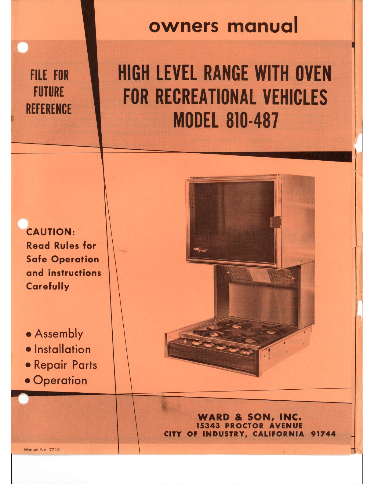
WARD & SON 810-487 Owner's Manual
fltE
ton
TUTURE
RETTRTlICE
HIGH
FOR
t|EHI
87
810-4
CAUTION:
Reod
Rules
for
Sofe Operotion
ond instructions
Corefully
Assembly
Instollotion
Repoir
Ports
o
o
o
Operotion
owners monuql
TEltEL RANOE
WITH
0ltE1{
CLES
RECREATIONAI
MODET
WARD &
sON, lNC.
15343 PROCTOR AVINU!
CITY
OF
INDUSIR,Y, CAIIFORNIA 91744
Manual
No.7214
instructions
r
RULES FOR
SAFE OPERATION
1.
Read the Owners
l\,4anual
and
these Rules
for
Safe Opera-
tion carefully.
2. Check
that all applicable state
and local codes
regarding
installation have
been followed.
In the
absence
of local
codes, the installation must conform with American
National Standard
Instaliation of Gas
Appliances and
Gas
Piping,
221.30'1964.
The
supplier
of the
propane
gas
is usually an expert
in this regard.
3.
Check that
minimum clearances
to combustible
materials
have
been
maintained.
4. Never
light matches in the
vicinity if the
odor of
gas
ts noreo.
5.
A window or other air
vent should
be opened slightly
'"vhile
using the range. Gas
burner flames consume oxygen
which has to be replaced
to assure
proper
combustion.
6.
Do not tamper
with the burner orifices
or change their
slze.
GENERAL
1.
Your High
Level Range
has been Certified
for
Perfor-
mance and
Safety by
The American Gas
Association
for
use with liquefied
petroleum
gases
only.
2.
Burner inputs are shown
on a
plate
attachgd
to each
appliance.
Refer to this
plate
for ratings and
minimum
clearances.
The orifices have been
sized at the
factory
at a
pressure
of 11
inches water column
(6-112
ounces
approximately)
for liquefied
petroleum
gases.
ASSEMBLY
Your new
range is fully assembled
with the
exception of the
main top, burner
grates,
and
grate
clip holddowns.
These
will be
placed
in or on
unit
after
range
installation is
completed.
INSTALLATION
l. Consider
the
following when selecting
the location
for
your
high
level range:
Location of
gas
supply and
routing of
gas
line.
l\4inimum
clearances of
unit from combustible
ma-
terials.
These clearances arel
Sides
-
2 inches
minimum as measured
from edge
of
burner box trim.
Rear Zero
inches.
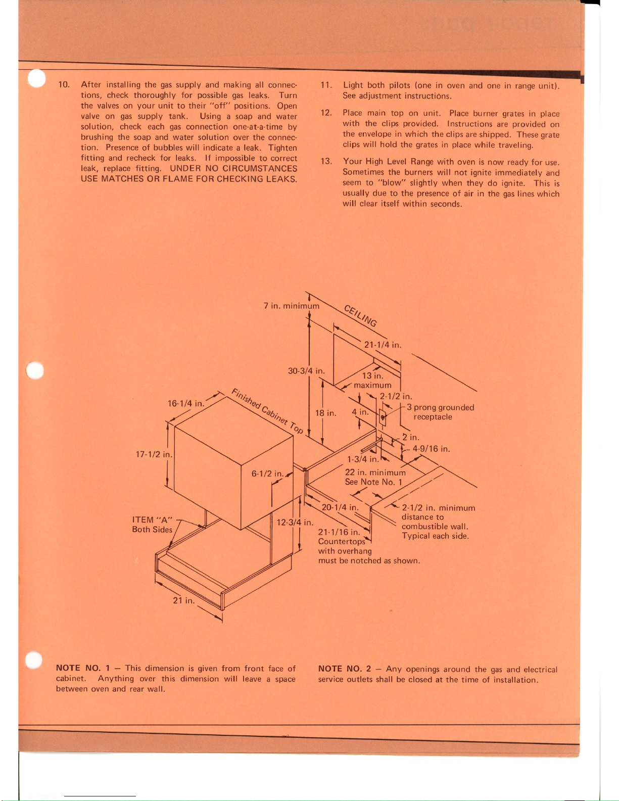
Top - 7 inches minimum as measured from top of
unit to ceiling.
After selecting
the
best
location, cut opening in counter-
top and overhanging cabinet as shown.
Install
gas
supply and route
gas
line
(not
furnished) to
range.
Here
you
should seek
the assistance of a
qualified
service man. Usually the supplier of
the
gas
will
be able
to
provide
expert help in this respect.
Too, he will
be
able to
provide
the
necessary
parts,
including the copper
gas
line. The following should be
carefully considered:
A. The
gas
tank must be
located in
a
protected place
and cannot UNDER
ANY CIRCUN4STANCES be
located within the confines of the trailer or camper.
The supplier of the
gas
will be acquainted
with the
applicable codes with
respect to the location of the
gas
supply
tank.
B. Gas supply
line
should
be copper and should be
routed in
protected
locations so as
not to
be damag-
ed. A single, continuous
line is recommended.
C.
No connections should be
made in the
gas
line
where the connections
would be concealed after
completion of the installation.
All
parts
used in
making
connections must be of type acceptable
for
this
purpose.
Gas line should
not make any sharp
bends nor have any
kinks. The line should not be
under
strarn.
D.
Install a manual shutoff valve
in
an accessible
loca-
tion in the
gas
supply
line external to the
range for
the
purpose
of
turning the
gas
on and off
during
servicing.
Install electrical
wiring in accordance with applicable
state and
local codes
for
110
volts A.C.. if
your
unit
is
equipped
with electrical equipment. See
cabinet cutout
for outlet location.
Place unit
partially
in installation area.
Do not
push
all
the
way into the cutout.
Reach behind the
oven
and
plug
in the service
cord if
equipped
with electrical
equ ipment.
Slide
unit into
position.
Secure
in
place
with 4 No. 8 wood screws
indicated as
item
"A"
in
cabinet cutout drawinE.
Make
gas
connection.
3.
2.
4.
5.
7.
8.
I
6.
B,
9.
10. After installing the
gas
supply and making
all connec-
tions.
check thoroughly
for
possible gas
leaks. Turn
the valves
on
your
unit
to their
"off"
positions.
Open
valve
on
gas
supply tank. Using
a soap and water
solution, check each
gas
connection one-at-a-time
by
brushing the soap and water
solution over the connec-
tion. Presence
of bubbles will indicate a leak. Tighten
fitting
and recheck for leaks. lf impossible
to correct
leak, replace fitting. UNDER NO CIRCUMSTANCES
USE MATCHES
OR
FLAI\4E
FOR CHECKING LEAKS.
7 in. minimum
11. Light both
pilots
(one
in
oven and one in range
unit).
See adjustment instructidns.
Place main
top on unit. Place
burner
grates
in
place
with the clips
provided.
Instructions
are
provided
on
the envelope in which
the clips
are shipped. These
grate
clips will hold
the
grates
in
place
while rraveling.
Your High
Level Range with
oven is now ready
for use.
Sometimes the
burners will not ignite
immediately
and
seem to
"blow"
slightly when they
do ignite. This is
usually
due to the
presence
of air in the
gas
lines which
will clear itself
within seconds.
18 in.
3
prong
grounded
receplacte
13.
.i
t\
I
I
3/4 in.30,
.a
'o^,
\ruo
16-1/4 in.
Qn".
z tn.
4-9l16
in.
17
-1/2
in.
1-3/4
in.
22 in. minimum
See Note No.
1
\<
20-1/4 in.
-
t^1,
,,, in.
minimum
NOTE NO,
1
-
This
dimension is
given
from front
face of
cabinet.
Anything over this
dimensjon will leave
a space
between
oven and rear wall.
21-1/16 in.
distance to
combustible
wall.
Typical
each
side.
Countertops
with
overhang
must be notched
as shown,
NOTE
NO. 2 - Any
openings around the
gas
and electrical
service outlets
shall be closed at the
time of installation.
ITEM
"A"
Both
Sides
12-314 in.
zt tn.
21-1/4 in.
tJ tn.
 Loading...