


USER MANUAL
Series 1000 A
Part Number 91-007-01
Firmware Release 1.00

Table of Contents
Table of Contents i
Preface 1
1 Introduction 1
1.1 Theory Of Operation 1
1.2 Features 1
1.3 What Is In The Box 2
2 Connectors, Lights, Switches, and Jumpers 3
2.1 Switches 3
2.2 Connectors 3
2.3 Lights 4
3 Start Up 4
3.1 Power 4
3.2 Connecting The Antenna 4
3.3 Connecting to the Ethernet Port – Administrative Connection 5
4 Administration, Configuration and Status 5
4.1 Getting Started 6
4.2 Interfaces 8
4.3 Services 14
4.4 Status 19
5 Specifications 22
6 Certifications 23

Preface
Welcome to the IIM Series 1000A Cellular Router User’s Guide. The User’s Guide will explain the basic
operation of a Cellular Router and take you through the necessary settings to get your wireless application
online. Additional information and applicable technical notices can be found at www.IIMproducts.com.
1 Introduction
Cellular Router provides application and network designers with a bridge between the world of IT
infrastructure and the evolving wireless data networks. With Cellular Router the wireless transport is fully
integrated into the product’s routing fabric meaning that you can approach the setup and operation of this
product much as with any other IP addressable device. Wireless considerations are reduced to the absolute
minimum necessary to register and make connections on a network.
1.1 Theory Of Operation
The Series 1000A Cellular Router is a complete IP router that routes traffic over LAN Ethernet
(10/100baseT) connections. The wireless features of Cellular Router simply extend the IP routing capabilities
to include routing and network address translation (NAT) over CDMA2000/1XRTT wireless networks. As
with most routers IIM’s Series 1000A Cellular Router can be viewed as having a Local Area Network (LAN)
side and a Wide Area Network (WAN) side. Traffic originating at Cellular Router’s Ethernet ports is
considered LAN traffic. The Wide Area Network connection is over the wireless network’s 1XRTT
transport.
1.2 Features

This manual covers Cellular Router (1000A) Release 1.00 and contains the following feature and functions.
1) Ethernet
a. Static Addressing
b. Dynamic (DHCP) Server
c. DHCP Client
d. Configurable DNS address
e. Configurable Gateway, Sub net mask, and Broadcast address
f. Port Forwarding
g. Service management
2) CDMA Interface
a. Enable/Disable Wireless Routing
b. Enable/Disable inbound IP requests
c. Adjust inactivity timers
d. Name Server Interoperability with UDP or SMS
e. DDNS Interoperability with BIND or MS Server
f. Administration web server port address selection
g. Enhanced OTA and manual activation
h. Home Network Selection
3) Relay Contact Closure (detection and operation)
a. NO/NC detection
b. SMS or email cry out alarm

4) Relay Driver Output
a. SMS Activation
b. Web Activation
5) General Administration
a. Modify Password
6) Status – Ethernet Status
a. Currently Assigned IP Address
b. Current MAC Address
7) Status – CDMA Status
a. ESN (Serial Number) Hex and Decimal
b. Network Assigned IP Address
c. Telephone Number (MIN)
d. Current Network Status Active/Inactive
e. Signal Level (RSSI)
1.3 What Is In The Box
The following items are included with your Cellular Router
1) Series 4100 Cellular Router
2) Antenna
3) 12VDC Power adapter

4) Cross over Ethernet cable
5) Documentation CD
2 Connectors, Lights, Switches, and Jumpers
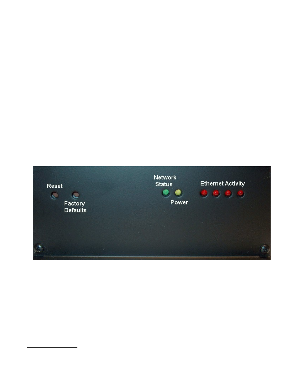
2.1 Switches
Referring to Figure 1, there are two switches on the back of the Series 4100E. S1 (Reset) causes a hard reset
of unit. S2 (Restore Defaults) is used to completely restore the firmware settings that were included when the
product was shipped from the factory.To restore factory defaults, the unit must be running. Press the Restore
Defaults (inner) switch and hold it down for 10 seconds. After 10 seconds, you will see both the green and
yellow lights go off. At that time you may either press the reset (outer) switch or cycle power on the unit.
Figure 1
2.2 Connectors
Ethernet Connectors

Connectors are found on the front of the Series 4100E Cellular Router . Ethernet ports 1 – 4 are auto polarity
sensing and can be used with either a standard Ethernet cable or a reverse (cross over) Ethernet cable.
Terminal Block
Connector J1 supports three separate functions, power, relay contact closure detection and the relay driver
output
The pin out configuration is as follows:
Pin 1 - +12VDC
Pin 2 - Ground
Pin 3 - Relay Out Control
Pin 4 - Relay Out Voltage Source 12vdc @40ma or less
Pin 5 - Relay In Sense
Pin 6 - Relay in Sense Voltage Source 3.3vdc with over current protection
Antenna Connector - Standard SMA type female connector.
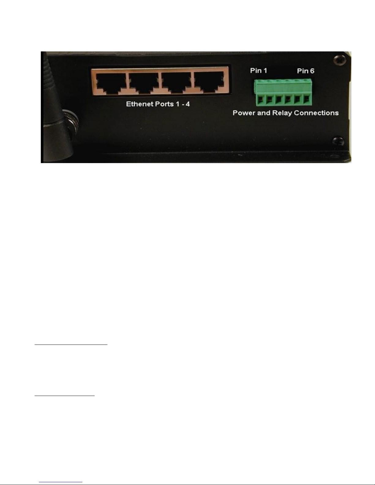
Figure 2
2.3 Lights
The Series 1000A Cellular Routerhas indicators as shown in Figure 1.
The network status indicator should be interpreted as follows:
NO IP CONNECTION - When there is no connection, the led will be in the off state. If there is low signal
(less than -88dBm) you will see one 200msc blink (on) every 4.5 seconds. if there is good signal quality, you
will see two 200msc blinks (on) every 4.5 seconds.
IP CONNECTION - If there is a connection, the led will be in the on state. If there is low signal, you will
see one 200msc blink (off) every 4.5 seconds. if there is good signal quality, you will see two 200msc blinks
(off) every 4.5 seconds.

3 Start Up
Warning – You must connect an antenna to the SMA style antenna connector on the Cellular Router
before turning it on. Failure to do this could result in erratic start up behavior and could possibly
damage the unit.
3.1 Power
Before starting connect the supplied 12VDC power adapter to the power connector described in Section 3.
The adapter supplied with your Cellular Router is suitable for use with 120VAC 60-hertz wall power. If you
need a different power solution contact IIM.
3.2 Connecting The Antenna
The antenna supplied with each Cellular Router should be attached to the SMA style antenna connector
described in section 3. The antenna must be connected before powering the unit on.
3.3 Connecting to the Ethernet Port – Administrative
Connection
For a direct Ethernet connection between a PC connect to any of the Ethernet ports using a standard or
reverse Ethernet cable. For initial configuration and administration with a PC or workstation IIM
recommends that the PC be set to obtain an IP address and obtain a DNS address automatically. For
Windows PCs make the following settings under the networking control panel
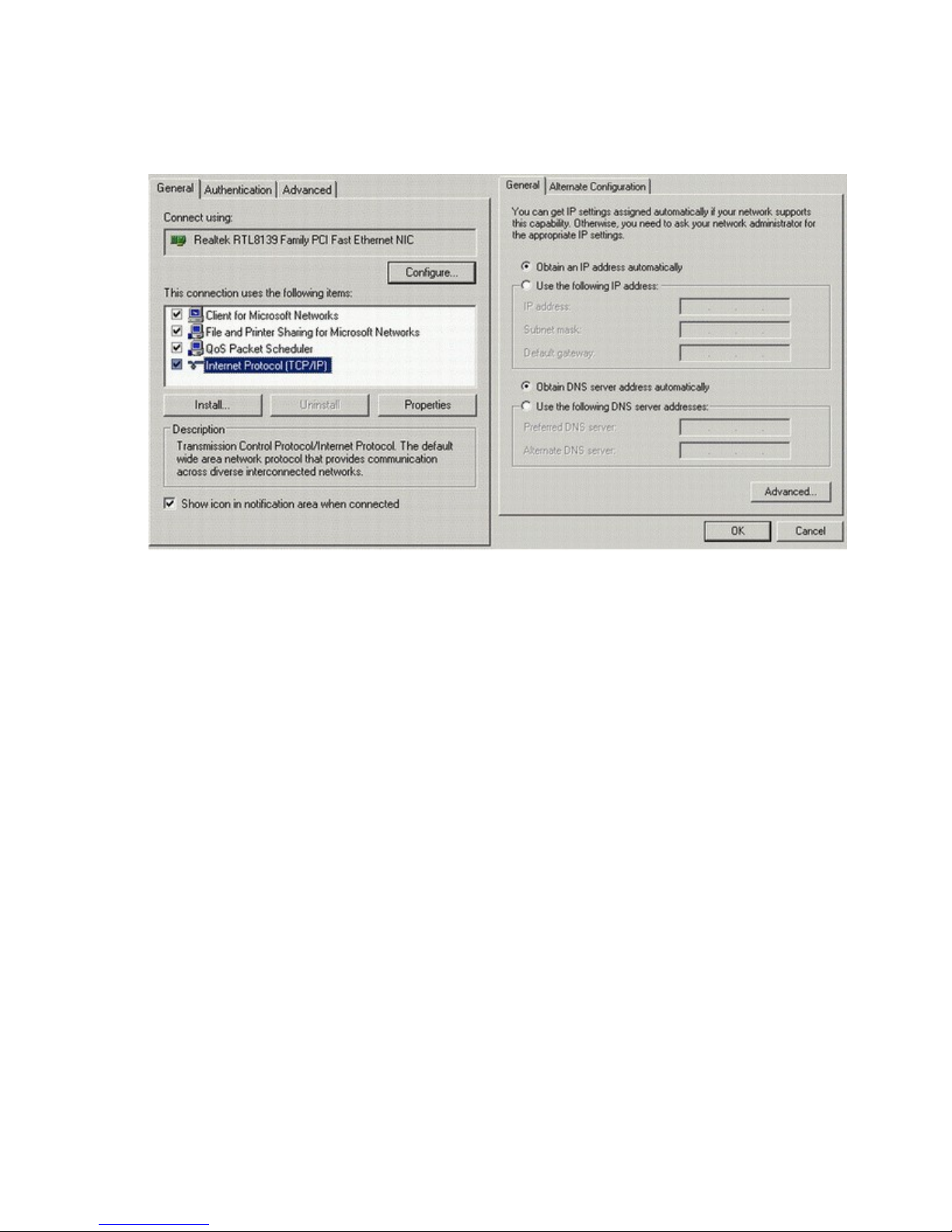
LAN (Ethernet) Connections - Windows
Figure 3
4 Administration, Configuration and Status
About Addressing – Devices connecting to CDMA/1XRTT networks are assigned an IP address by the
serving network. Address assignment may either be static or the unit will be dynamically assigned an IP
addresses, depending on arrangements that you have made with your wireless network operator. Dynamically
assigned IP address remain in effect for a period of time assigned by the network operator, usually at most a
small number of hours.
IIM’s Cellular Router includes features that manage the temporal nature of dynamically assigned wireless IP
addresses. Using the Wireless Configuration screen you can configure your Cellular Router to use a
Dynamic DNS (DDNS) service. IIM operates a DDNS test bed that allows our customers to observe the
performance and reliability of DDNS with their applications. For large-scale commercial applications IIM
recommends that users configure their own DDNS, managed and maintained with the customers ongoing IT
operations. Any Series 4100 Cellular Router can be configured to operate as a DDNS using IIM’s
proprietary Enhanced Wireless DNS (EW/UDP or EW/SMS). The Cellular Router may also be configured
to operate with a standard DNS having Dynamic DNS capabilities. Examples of this type of service would be
Berkeley Internet Name Daemon (BIND) and Microsoft Server 2000 and up. For detailed information see IIM’s TechNote
S4100-01.
 Loading...