

Wantegrity HAWK-800 Owner's Manual
-1-
HAWK-800 Programmable Polyphonic Synthesizer
Upgrade Kit
Thank you and congratulations on your choice of the HAWK-800
upgrade kit. This kit has been engineered for highest quality
sounds and superb reliability. To obtain optimum performance
from your new HAWK-800, please read this manual carefully
before using.
-2-

Features of the HAWK-800
1. New “Global” mode allows setting up many new MIDI parameters and operational
configurations.
2. New “Extended” parameter editing mode allows editing numerous new sound parameters.
3. Flash software upgrade capability allows new software to be uploaded to the synthesizer via
SYSEX.
4. The sequencer now has 7 individual sequencer memories and any one of the sequences can be
chosen for playback in real time while the sequencer is in operation.
5. Portamento Mono mode operation.
6. Local control mode selection for both the Keyboard and Sequencer.
7. Sequencer note follow mode allows the sequencer to shift notes to match latest played note.
8. In advanced sequencer mode, you can edit up to seven different sequences and each one can
be selected to play in real time. Sequences can be locked to protect them from accidental
editing. The sequencer edit display shows the number of quarter notes per bar rather than the
original impossibly difficult counter.
9. There are now two general purpose LFO's (LFO1 and LFO2) and two SLFO's (SLFO3 and SLFO4).
All LFO's have triangle, sawtooth, sine, square (with PWM) and random sample and hold
waveforms. All waveforms can be inverted.
10. All four LFO's can be set to free running modes.
11. Both LFO1 and LFO2 can be set to modulate until the delay time expires.
12. Per patch SYSEX dump send and receive, bulk patch dump.
13. You can edit parameters using the joystick.
14. A sustain pedal can be used in the Step Up jack along with three different sustain modes.
15. MIDI note velocity sensitivity!
16. And many more...
-3-

Table of Contents
HAWK-800 Programmable Polyphonic Synthesizer Upgrade Kit..............................................................2
Features of the HAWK-800........................................................................................................................3
Functions and Operations..........................................................................................................................8
1. Before You Begin...............................................................................................................................8
Finding Your Way Around..........................................................................................................................8
Front Panel............................................................................................................................................8
Poly-800 MK1 and MK2 Key Assign Mode............................................................................................8
EX-800 Key Assign Mode.......................................................................................................................8
Global Parameter Editing Mode............................................................................................................8
Entering and Exiting Global Mode....................................................................................................9
Global Mode Executable Commands....................................................................................................9
How to execute a global executable command...............................................................................9
11 GL 11 = No operation...................................................................................................................9
11 GL 12 = All notes off (Panic Button).............................................................................................9
11 GL 13 = SYSEX bulk dump all patches..........................................................................................9
11 GL 14 = SYSEX dump single patch................................................................................................9
11 GL 15 = SYSEX dump single patch................................................................................................9
11 GL 16 = SYSEX dump sequencer data........................................................................................10
11 GL 17 = SYSEX dump global parameters....................................................................................10
11 GL 25 = Jump into flash update routine....................................................................................10
11 GL 26 = Jump into diagnostics mode.........................................................................................10
Global Mode Parameters....................................................................................................................10
12 GL xx - Selected patch or parameter.........................................................................................10
13 GL xx – Patch Bank Select..........................................................................................................10
14 GL xx - Sequencer clock internal/external.................................................................................10
15 GL xx - Program change enable.................................................................................................11
16 GL xx – NRPN MSB Device Select...............................................................................................11
17 GL xx – Sustain Pedal Operation Select.....................................................................................11
18 GL xx - Portamento fine tuning..................................................................................................11
21 GL xx - Omni on/off/auto...........................................................................................................11
22 GL xx - Keyboard MIDI transmit select......................................................................................11
23 GL xx - Local Keyboard control..................................................................................................11
24 GL xx - Local Sequencer control.................................................................................................12
25 GL xx - Sequencer MIDI time code send....................................................................................12
26 GL xx - Sequencer MIDI transmit channel.................................................................................12
27 GL xx - MIDI receive channel.....................................................................................................12
28 GL xx - MIDI soft thru.................................................................................................................12
31 GL xx - Extended playing range..................................................................................................12
32 GL xx - Cascading unit number..................................................................................................12
33 GL xx - Cascading sync mode.....................................................................................................13
34 GL xx - Device type.....................................................................................................................13
-4-

35 GL xx - Keyboard MIDI transmit note octave offset..................................................................13
36 GL xx - Keyboard MIDI transmit note velocity offset................................................................13
37 GL xx - Sequencer note follow mode.........................................................................................13
38 GL xx – Velocity sensitive trigger delay.....................................................................................14
41 GL xx - Joystick MIDI TX channel number..................................................................................14
42 GL xx - Local Joystick control off................................................................................................14
43 GL xx – Extended Sequencer Mode Beats per Bar....................................................................14
44 GL xx – Default Selected Sequence...........................................................................................15
45 GL xx – Note Event Fast Response Timer..................................................................................15
46 GL xx – Sequencer ¼ Note Ticks................................................................................................15
51(-57) GL xx – Sequence Edit Write Protect.................................................................................15
86 GL xx – Display MIDI transmitted bytes counter.......................................................................15
87 GL xx – Display MIDI received bytes counter............................................................................15
88 GL xx – Display MIDI received bytes parity error counter.........................................................15
Original Parameter and Extended Parameter Editing Mode..............................................................15
Parameter Edit Modes....................................................................................................................16
Remapped Original Parameters.....................................................................................................16
P1 Parameter Groups.....................................................................................................................16
P1 Parameters 11-18, 21-27...........................................................................................................17
P1 13,23 – DCO harmonics selector...............................................................................................17
P1 14,24 – DCO harmonics modulation waveform selector..........................................................17
P1 15,25 – DCO harmonics modulation LFO selector....................................................................18
P1 16,26 – DCO harmonics modulation depth...............................................................................18
MK2 Effects Unit Group..................................................................................................................18
P1 34 – MK2 Effects Unit Delay Time.............................................................................................18
P1 35 – MK2 Effects Unit Feedback................................................................................................18
P1 36 – MK2 Effects Unit Modulation Frequency..........................................................................18
P1 37 – MK2 Effects Unit Modulation Intensity.............................................................................18
P1 38 – MK2 Effects Unit Volume Level.........................................................................................18
VCF Group.......................................................................................................................................18
P1 41 – VCF Cut Off Set Point.........................................................................................................18
P1 42 – VCF Keyboard Tracking......................................................................................................18
P1 43 – VCF EG3 Polarity................................................................................................................19
P1 44 – VCF EG3 Intensity...............................................................................................................19
P1 45 – EG3 Trigger.........................................................................................................................19
P1 46 – MK2 Bass Equalization.......................................................................................................19
P1 47 – MK2 Treble Equalization....................................................................................................19
P1 48 – MK1 and EX-800 Chorus Effect..........................................................................................19
P1 Parameters 51-56, 61-66 and 71-76 – Envelope Generators EG1, EG2 and EG3.....................20
Velocity Effects Group....................................................................................................................20
P1 81, 84 – OP1, OP2 Velocity Intensity.........................................................................................20
P1 82, 85 – OP1, OP2 Velocity Intensity Invert..............................................................................20
P1 83, 86 – OP1, OP2 Velocity Target.............................................................................................20
P1 87 – VCF Velocity Intensity........................................................................................................20
-5-

P1 88 – VCF Velocity Shape............................................................................................................21
P2 Parameter Groups.....................................................................................................................21
LFO1 and LFO2 Group.....................................................................................................................21
P1 11, 21 – LFO1, LFO2 frequency..................................................................................................21
P2 12, 22 – LFO1, LFO2 delay timer................................................................................................21
P2 13, 23 – LFO1, LFO2 free running..............................................................................................21
P2 14, 24 – LFO1, LFO2 delay invert...............................................................................................22
P2 15, 25 – LFO1, LFO2 PWM phase...............................................................................................22
P2 16, 26 – LFO3/4 waveform for LFO1/2 frequency modulation.................................................22
P2 17, 27 – LFO3/4 modulation depth of LFO1/2 freq. modulation..............................................22
P2 18 – LFO1 sync driven cycle reset..............................................................................................22
P2 28 – LFO2 sync driven frequency...............................................................................................23
DCO Modulation Group..................................................................................................................23
P2 31 – DCO LFO waveform selector..............................................................................................23
P2 32 – DCO LFO modulation source selector................................................................................23
P2 33 – DCO LFO modulation depth...............................................................................................23
P2 35 – DCO EG invert....................................................................................................................23
P2 36 – DCO EG depth....................................................................................................................23
P2 38 – DCO Modulation mode......................................................................................................24
VCF Modulation Group...................................................................................................................24
P2 41 – VCF 1st LFO waveform selector.........................................................................................24
P2 42 – VCF 1st LFO modulation source selector...........................................................................24
P2 43 – VCF 1st LFO modulation depth..........................................................................................24
P2 44 – VCF 2nd LFO waveform selector........................................................................................24
P2 45 – VCF 2nd LFO modulation source selector..........................................................................25
P2 46 – VCF 2nd LFO modulation depth.........................................................................................25
P2 48 – VCF 12/24db filter selector **...........................................................................................25
Resonance Modulation Group........................................................................................................25
P2 51 – Resonance set point..........................................................................................................25
P2 52 – Resonance LFO modulation waveform selector................................................................25
P2 53 – Resonance LFO modulation source selector.....................................................................26
P2 54 – Resonance LFO modulation depth....................................................................................26
P2 56 – Resonance EG depth..........................................................................................................26
P2 57 – Resonance EG invert..........................................................................................................26
P2 58 – Aggressive Resonance**....................................................................................................26
FM/Noise Modulation Group**.....................................................................................................26
P2 61 – FM800 set point**.............................................................................................................27
P2 62 – FM800 LFO modulation waveform selector**..................................................................27
P2 63 – FM800 LFO modulation source selector**........................................................................27
P2 64 – FM800 LFO modulation depth**.......................................................................................27
P2 66 – FM800 EG depth**............................................................................................................27
P2 67 – FM800 EG invert**............................................................................................................27
P2 68 – FM800 Mode**..................................................................................................................27
SLFO Group.....................................................................................................................................28
-6-

P2 71 – SLFO3 frequency................................................................................................................28
P2 72 – SLFO3 PWM phase.............................................................................................................28
P2 73 – SLFO3 free running............................................................................................................28
P2 74 – Sequencer/MIDI clocked Random Sample and Hold Ticks................................................28
P2 75 – SLFO4 frequency................................................................................................................28
P2 76 – SLFO4 PWM phase.............................................................................................................28
P2 77 – SLFO4 free running............................................................................................................29
P2 78 – Sustain Pedal Decay/Sustain Offset...................................................................................29
Tremolo and Special Parameters Group........................................................................................29
P2 81 – Tremolo DCO1 mode and LFO source...............................................................................29
P2 82 – Tremolo DCO1 LFO modulation depth..............................................................................29
P2 83 – Tremolo DCO2 mode and LFO source...............................................................................29
P2 84 – Tremolo DCO2 LFO modulation depth..............................................................................29
P2 85 – Bend Depth........................................................................................................................30
P2 86 – Portamento Rate...............................................................................................................30
P2 88 – Poly Mode..........................................................................................................................30
General Hints and Tips.............................................................................................................................30
Initializing Patch Flash Memory..........................................................................................................30
Ribbon Header Cable Troubles............................................................................................................30
MIDI Hints and Tips..................................................................................................................................31
MIDI System Exclusive Messages........................................................................................................31
Receiving EX-800 or Poly-800 Mk2 Sysex Bulk Data.......................................................................31
MIDI Controller Messages...................................................................................................................31
MIDI CC Non Registered Parameter Number Method...................................................................31
MIDI CC “Quick Parameter Change” Method.................................................................................31
MIDI CC “Hardware Controller Friendly” Method..........................................................................32
Miscellaneous Information......................................................................................................................32
Flash Memory Backup.........................................................................................................................32
Lithium Backup Battery.......................................................................................................................32
Tools Mode..........................................................................................................................................32
Tools Function 1 - Display Software Versions................................................................................33
Tools Function 2 - Validate Patch Memory....................................................................................33
Tools Function 3 - Clear Global Memory........................................................................................33
Tools Function 4 - System Memory Inspection.............................................................................33
Tools Function 7 – Patch Bank Dump to System Exclusive Message.............................................33
Tools Function 8 - Uploading Patch Sets using System Exclusive Message...................................34
Performance Considerations...............................................................................................................35
Sequencer Advanced Mode................................................................................................................35
Real Time Advanced Sequencer Editing Operations...........................................................................38
Power On Functions.................................................................................................................................38
SourceForge HAWK800 Project...............................................................................................................39
-7-
Functions and Operations
1. Before You Begin
This owner's manual applies to the Korg Poly-800 MK1, the Korg Poly-800 MK2 or the Korg EX-800 synthesizer module
where the instruments have been upgraded to include the HAWK-800 retrofit hardware kit. If you are not sure if your
Poly-800 or EX-800 has the kit installed you can test this by observing the display when you turn the synthesizer on.
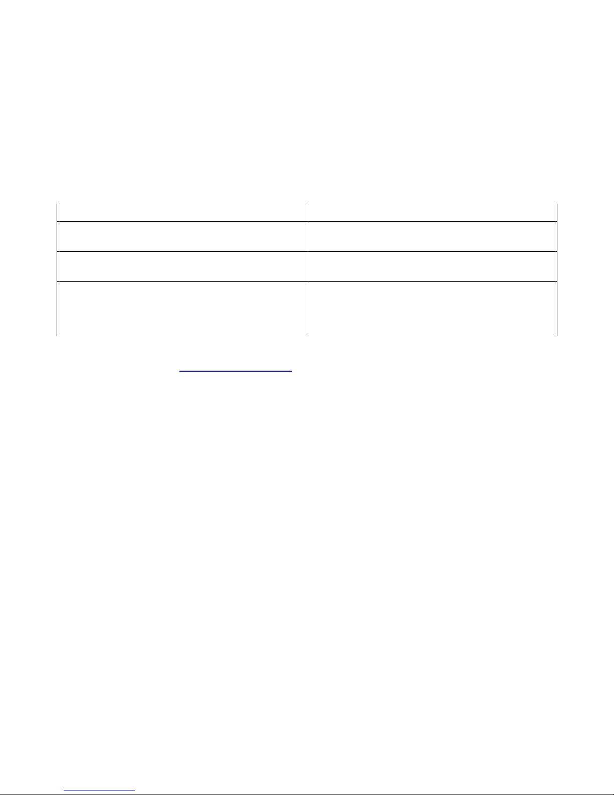
At power on, a HAWK-800 upgraded Poly-800 will show various messages depending upon the boot software that is
installed in the HAWK-800.
Boot ROM Software Version Power Up Messages
Boot software versions 1.1 - 1.4 The display will briefly show “P1 X” where X is the minor
version number.
Boot software version 1.5 The display will briefly show “P1 5E XX” where XX is the
flash software version number.
Boot software version 1.6 and higher The display will show “HA-800” for approximately 5
seconds. If you press and hold the “Bank Hold” button
during boot up then the HAWK-800 will display its progress
through the boot up power on self tests.
If your Poly-800 displays “11 P” immediately after power on then it has not been upgraded with the HAWK-800 kit. You
can obtain the upgrade kit at: http://www.hawk800.com/
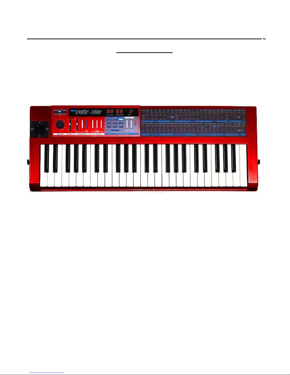
Finding Your Way Around
Front Panel
There are four major differences between the operation of the front panel buttons and the original Korg Poly-800 or EX-
800.
Poly-800 MK1 and MK2 Key Assign Mode
The original Poly-800 MK1 and MK2 has three key assign mode buttons. They are the Poly, Chord and Hold mode buttons.
All three buttons are still used to enter the original modes. However, the “Poly” button now also doubles as a way to enter
into Portamento mono mode. Pressing the “Poly” button will toggle the Poly-800 between polyphonic mode (the display
will show “P”) and Portamento mono mode (the display will show an “S” meaning slide mode). A Poly-800 MK1 or MK2
that is fitted with the HAWK-800 upgrade kit can both send and receive MIDI controller messages to change the key assign
mode. See the MIDI implementation chart for details.
EX-800 Key Assign Mode
The original EX-800 has no key assign mode buttons. However, an EX-800 that is fitted with the HAWK-800 upgrade kit can
be sent MIDI controller messages to change the key assign mode. Also, an EX-800 can be set up in tandem with a master
Poly-800 so that it receives key assign commands from the Poly-800. See the MIDI implementation chart for details.
Global Parameter Editing Mode
As the name suggests, global mode provides a way to control various global aspects of the Poly-800 and EX-800 that apply
-8-

to all patches and to the overall operation of the synthesizer.
Entering and Exiting Global Mode
To enter global mode, make sure that you are in program (patch) selection mode (in other words, you should not be in
parameter editing mode) and press the “Step” key.
When you have entered Global mode the display will change to show 11 GL 11. The first 11 refers to the selected global
parameter. The “GL” indicates that the synthesizer is in global parameter edit mode and the second 11 indicates the data
value of the global parameter.
There are two types of global parameters. They are global commands and global parameters.
Press the “Step” key to exit global mode at any time.
Global Mode Executable Commands
To execute a global command requires using the keypad to select global parameter 11 and then selecting a command to
execute using the data up and down buttons.
How to execute a global executable command
1. Select the global parameter number for executable commands: “11”.
2. Select the desired command using the “Up” and “Down” value buttons.
3. Press the “Write” button to execute the command.
The following executable commands are implemented in the HAWK-800 software:
11 GL 11 = No operation
No command is executed if you select executable parameter 11 and set the data value to 11 and press the
“Write” key. This ensures that you don't accidentally execute a command if you enter Global mode and press the “Write”
key in error.
11 GL 12 = All notes off (Panic Button)
The synthesizer resets all sounding notes and will send the all notes off MIDI message on the currently selected
keyboard MIDI transmit channel if it has been set to a channel. If the keyboard MIDI transmit channel is set to zero then
the MIDI all notes off message will not be sent.
11 GL 13 = SYSEX bulk dump all patches
The synthesizer sends a sequence of 64 individual SYSEX single patch dumps of all of the patches (11-88). The
individual SYSEX patch dumps are paced out of the MIDI port at a rate that any HAWK-800 can receive. You should not
send any other SYSEX commands to the HAWK-800 until the SYSEX dump send is completed.
11 GL 14 = SYSEX dump single patch
The synthesizer sends a SYSEX single patch dump of the patch selected by global parameter 12. This means that
you should first set the appropriate desired patch number in global 12 prior to executing this command.
11 GL 15 = SYSEX dump single patch
The synthesizer sends a SYSEX single patch dump of the currently select patch. This means that you should first
-9-

set the appropriate desired patch number before entering global mode and executing this command.
11 GL 16 = SYSEX dump sequencer data
Pressing the “Write” key will cause the synthesizer to send a SYSEX dump of the stored sequencer data. This
means that you can send (and receive) individual recorded sequences without using the sysex bulk dump commands.
11 GL 17 = SYSEX dump global parameters
Pressing the “Write” key will cause the synthesizer to send a SYSEX dump of the Global parameters. This can be
used to synchronize a slave Poly-800 or EX-800 unit. It can also be used to save the Poly-800 global settings in a sequencer
program or computer utility in order to later bring the Poly-800 or EX-800 into a particular global configuration mode. See
the MIDI implementation chart for details.
11 GL 25 = Jump into flash update routine
Pressing the “Write” key will cause the synthesizer to jump into flash ROM upgrade mode. See Upgrading the
Software on your HAWK-800 for flash ROM upgrade instruction.
11 GL 26 = Jump into diagnostics mode
See the section on Diagnostics Mode later in this manual.
Global Mode Parameters
Global parameters are those numbered from 12 through to 88. Not all parameters in the range are implemented. If you
select a global parameter that is not implemented then the data display will be blanked out. You edit global parameters by
using the keypad to select the desired parameter and then using the up and down buttons to set the value for that global
parameter. There is no need to write a global parameter as the value is immediately set by the up or down buttons when
you press them and is saved in flash memory immediately.
12 GL xx - Selected patch or parameter
xx = 11 through 88.
Allows setting the selected patch or parameter number. This value is then used by other global executable commands to
carry out certain actions.
13 GL xx – Patch Bank Select
x = 1 through 4.
Allows selecting one of four different patch banks. HAWK-800 kits produced after May 2009 are all fitted with a 32K flash
ROM for patch storage. This large flash memory is capable of storing 256 patches. Global parameter 13 allows selecting
one of four banks of 64 patches. Changing the bank does not change the currently operating patch so it is possible to
change the patch bank without interrupting any current sounding notes. To select a patch from the new selected patch
bank requires then exiting global mode and then selecting a desired patch. Patch bank selection can also be engaged by
sending a bank select MIDI controller message. See the MIDI implementation chart for details.
14 GL xx - Sequencer clock internal/external
xx = 1=internal or 2=MIDI
Determines if the sequencer clock is internally generated and controlled by the sequencer speed slider or is clocked by
-10-

external MIDI clock.
15 GL xx - Program change enable
xx – 0=disable, 1=enable
Incoming MIDI program change that are received on the selected MIDI receive channel are ignored when this parameter is
set to zero. When set to 1, the synthesizer will respond to incoming MIDI program change messages.
16 GL xx – NRPN MSB Device Select
xx – 0-63
MIDI NRPN controller messages can be used to set the value of any original or extended parameter. The NRPN LSB
determines the parameter to be changed. The NRPN MSB must match global parameter 16. NRPN messages with an MSB
that does not match global 16 are ignored. See the MIDI implementation chart for additional details. NRPN messages
MUST be sent as three consecutive messages starting with the MSB, followed by the LSB and then the data value.
Generally this global parameter should be set to one (1) since any MIDI templates that are released by the HAWK-800
team will use an NRPN MSB equal to one.
17 GL xx – Sustain Pedal Operation Select
xx - 0=Pedal Jack operates as Program Up
1=Pedal will hold notes at sustain level
2=Decay and Release will be extended by extended parameter 78
3=Both mode 1 and 2 combined.
The pedal jack on the rear of the Poly-800 was originally designed to operate as a way to slowly work through the patches
by selecting the next higher patch each time the pedal is depressed. Global parameter 17 now allows the Poly-800 or EX800 to operate with a full sustain pedal operation.
18 GL xx - Portamento fine tuning
xx – 00-63
Allows setting the DCO modulation bend interval for portamento mono mode. For additional details see the section –
Calibrating Portamento Mono Mode. The default setting for the portamento fine tuning will generally be nine (9).
21 GL xx - Omni on/off/auto
xx - 0=omni auto (on at power on), 1=omni off (including at power on)
For most configurations it is desirable to have your synthesizer start up in Omni off mode.
22 GL xx - Keyboard MIDI transmit select
xx – 0=Off, 1-16=keyboard MIDI transmit channel
0=no MIDI keyboard transmit, 1-16 selects the MIDI transmit channel
23 GL xx - Local Keyboard control
xx - 0=off, 1=on
Setting local keyboard control to off stops the keyboard from triggering the sound generation of the synthesizer. This
-11-

means that you can use your synthesizer to transmit MIDI data to another MIDI instrument while your synthesizer can
play its own sequencer or even respond to incoming MIDI data.
24 GL xx - Local Sequencer control
xx - 0=off, 1=on
Setting local sequencer control to off stops the sequencer from triggering the sound generation of the synthesizer. This
means that you can use your synthesizer to transmit MIDI data while you continue to play the keyboard to generate
sounds on the synthesizer.
25 GL xx - Sequencer MIDI time code send
xx - 0=no, 1=yes
Setting this parameter to no allows the sequencer to send just the note data without MIDI sequencer clock messages.
Setting this parameter to 1 causes the synthesizer to transmit MIDI sequencer clock messages. This parameter does not
affect the transmission of start or stop MIDI messages when those buttons are pressed on the front panel.
26 GL xx - Sequencer MIDI transmit channel
xx – 0=Off, 1-16=sequencer MIDI transmit channel
0=no MIDI sequencer transmit, 1-16 selects the MIDI transmit channel
27 GL xx - MIDI receive channel
xx – 1-16
Determines the MIDI receive channel to which the synthesizer will respond.
28 GL xx - MIDI soft thru
xx – 0=off, 1=on
This parameters allows setting the HAWK-800 so that it retransmits MIDI data messages that are received on the MIDI “in”
port and retransmits them on the MIDI “out” port. This is useful if you wish to cascade MIDI devices. You should not use
this feature except to cascade another Poly-800 or EX-800 together in a master and slave configuration.
31 GL xx - Extended playing range
xx – 0=off, 1=on
Will set operating the currently selected patch to octave 2 position and will turn off note correction one octave above and
one octave below the keyboard range. This allows the Poly-800 and EX-800 to respond to MIDI note messages across six
octaves instead of the four that the original keyboard used. To do this, the octave parameters 11 and 21 are set to their
mid point.
32 GL xx - Cascading unit number
xx - 0=off, 1=play odd notes, 2=play even notes
This parameter allows two Poly-800's or EX-800's to be set up so that they work in tandem to play odd and even notes
individually. This provides an increase in the Polyphony (number of simultaneous notes being played). This requires that
-12-
 Loading...