

wantai DQ542MA User Manual
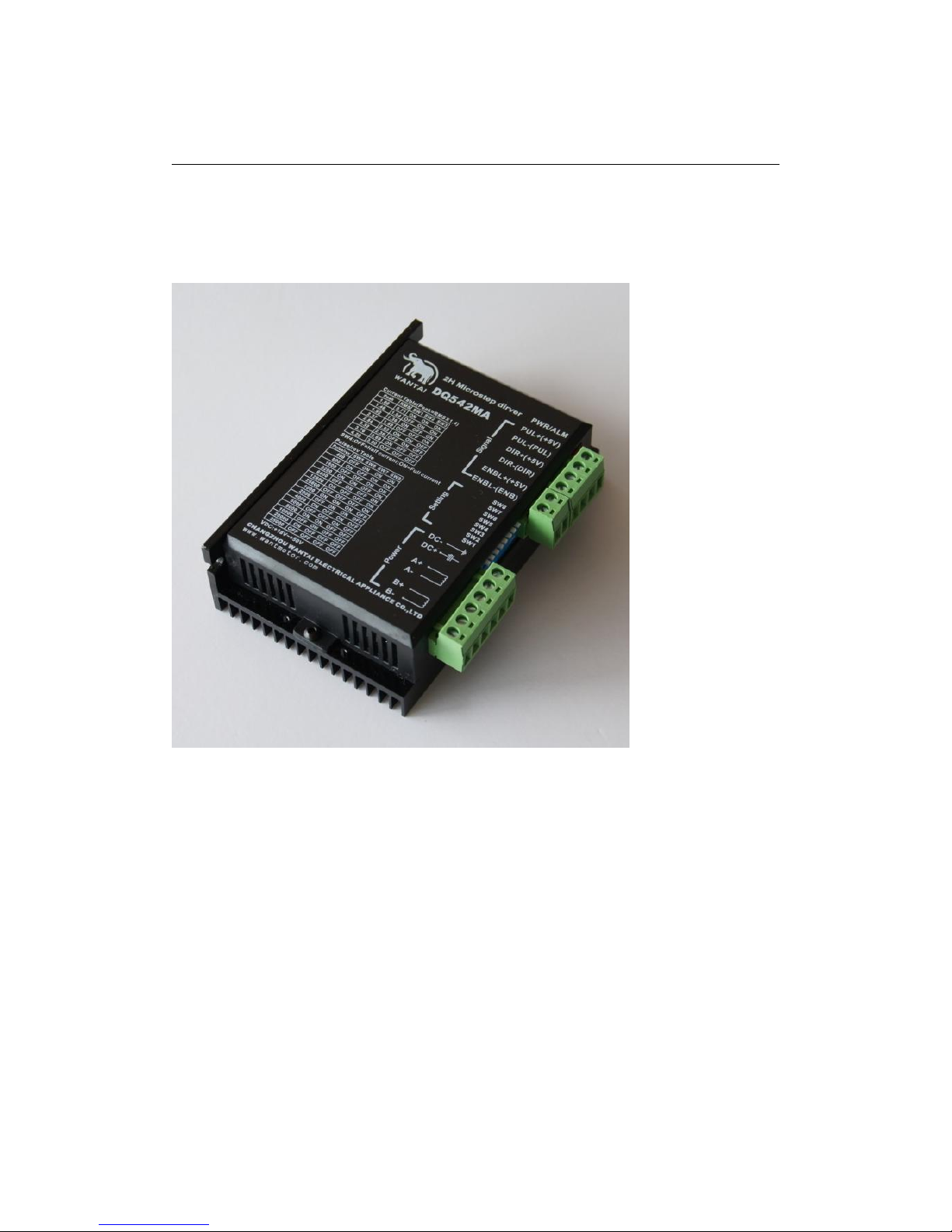
Manual of 2-phase hybrid stepper motor driver DQ542MA
Introduction:
DQ542MA is a type of two-phase hybrid stepping motor driver, the drive voltage of which is
from 18VDC to 50VDC. It is designed for use with 2-phase hybrid stepper motor of all kinds
with 42mm to 86mm outside diameter and less than 4.0A phase current. This circuit that it
adopts is similar to the circuit of servo control which enables the motor run smoothly almost
without noise and vibration. Holding torque when DQ542MA run under high speed is also
significantly higher than the other two-phase driver, what’s more, the positioning accuracy is
also higher. It is widely used in middle and big size numerical control devices such as curving
machine, CNC machine, Computer embroider machine, packing machines and so on.
Features:
High performance, low price
Average current control, 2-phase sinusoidal output current drive
Supply voltage from 18VDC to 50VDC
Opto-isolated signal I/O
Overvoltage, under voltage, overcurrect, phase short circuit protection
15 channels subdivision and automatic idle-current reduction
8 channels output phase current setting
Offline command input terminal
Motor torque is related to speed, but not related to step/revolution
High start speed
High holding torque under high speed
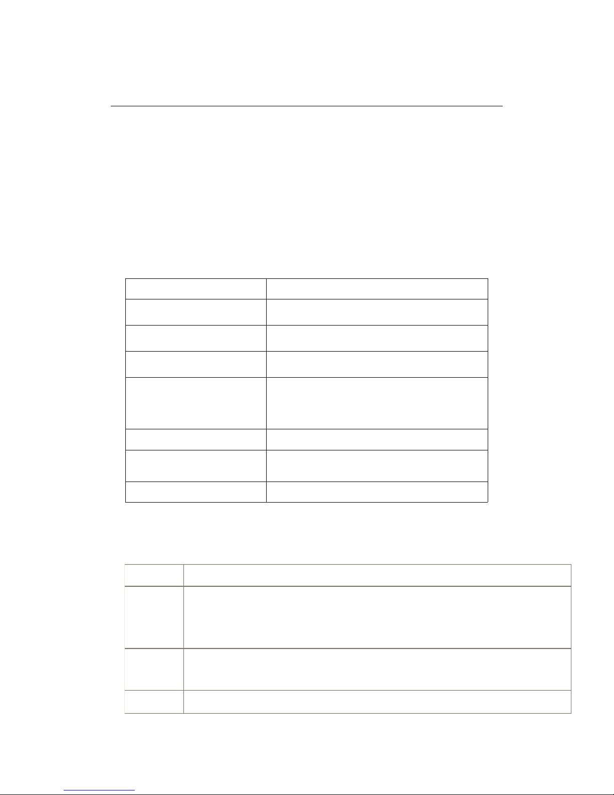
Electrical specification:
Input voltage
18-50VDC
Input current
< 4A
Output current
1.0A~4.2A
Consumption
Consumption:80W; Internal Insurance:6A
Temperature
Working Temperature -10~45℃
;
Stocking temperature -40℃~70℃
Humidity
No condensation, no water droplets
gas
Prohibition of combustible gases and conductive
dust
weight
300GS
1. Pins assignments and description:
1) Connector Pins Configurations
Pin Function
Details
PUL +,PUL-
Pulse signal, PUL+ is the positive end of pulses input pin
PUL- is the negative end of pulse input pin
DIR+,DIR-
DIR signal: DIR+ is the positive end of direction input pin
DIR- is the negative end of direction input pin
ENBL+
Enable signal: ENBL+ is the positive end of direction input pin. This signal is used for
enabling/disabling the driver. High level for enabling the driver and low level for disabling the
driver.
ENBL-
ENBL- is the negative end of direction input pin. Usually left unconnected (enabled)
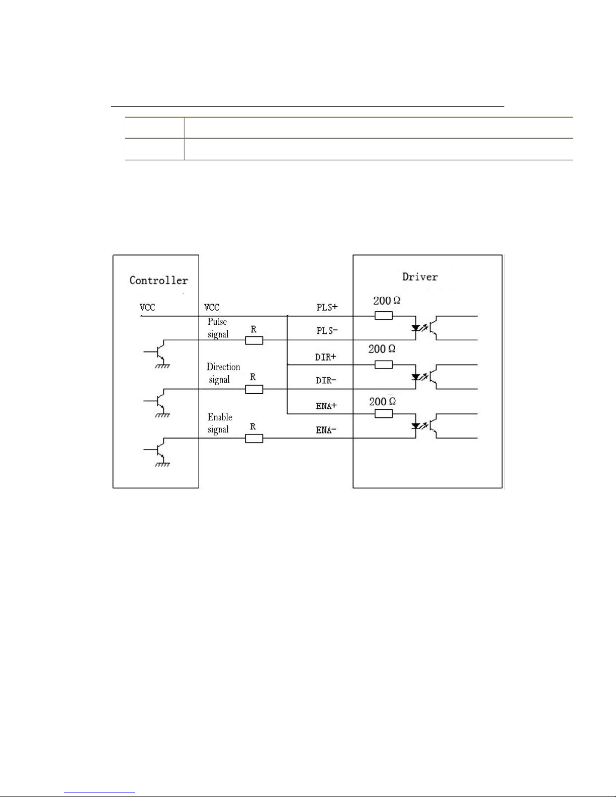
2) Pins wiring diagram:
PC’s control signals can be active in high and low electrical level. When the high electrical
level is active, all control negative signals will be connected together to GND. When low
electrical level is active, all control positive signals will be connected together to public port.
Now give two examples ( Open collector &PNP), please check them:
Fig 1. Input port circuit (Yang connection)
PC open connector output
 Loading...