

Page 1

IP
IP
Camera
Camera
((SmartP2P
SmartP2P))
NCM
NCM
series
series
User
User
manual
manual
October 2014
Rev 1.2
Please read and understand this manual
before attempting installation of the product.
Page 2

http://www.wansview.com
2
Statement
If the user manual doesn’t help you to resolve the problem, please call our technology center
for technical support.
Notice
1、 Installation Environment
Keep away from the places for high-temperature, heat source and direct sunlight;
Keep away from water and if wet, cut off the power immediately.
Avoid using in a damp environment; the reference range for operation humidity is below
85%RH.
Avoid using in too hot and too cold environment, the reference range for operation
temperature is -10℃~ +50℃
Please install it horizontally or wall mount, avoid strenuous vibration and do not place
other items on top of the unit.
2、 Transport and Handling
Please handle the item with care.
Do not use in areas around condensation.
Please disconnect the item from the mains before moving.
Notice:
1. Be careful not to damage the camera or subject it to strong impacts or shocks.
2. Do not touch the optical components for the image sensor, such as the lens, if
necessary, please place a clean and moistened cloth with alcohol and wipe the dirt
gently; When not in use, please place the dust cover on to the item to protect the image
sensor.
3. Do not aim the camera directly into the sun or at other intense light sources that could
affect the image quality, this will also shorten the service life for the image sensor.
4. Keep away from laser when it is working, otherwise the image sensor can be damaged.
5. If the equipment is not working properly, please contact the store or the service centre,
do not disassemble or modify the equipment in any way.
Page 3

http://www.wansview.com
3
Index
1. PRODUCT INTRODUCTION........................................................................................................5
1.1. PRODUCT SUMMARY.................................................................................................................. 5
1.2. PACKAGE FOR TYPICAL PRODUCTION.........................................................................................5
2. INSTALLATION AND OPERATION GUIDE.............................................................................. 8
2.1. VIEW VIDEO BY MOBILE PHONE SOFTWARE................................................................................8
2.2. VIEW VIDEO BY WIRED CONNECTION IN LAN............................................................................8
2.3. VIEW VIDEO BY WIFI CONNECTION IN LAN............................................................................ 11
2.4. VIEW VIDEO IN INTERNET.........................................................................................................12
2.5. VIEW VIDEO BY PC CLIENT SOFTWARE.................................................................................... 14
2.6. VIEW VIDEO BY OTHER WAY.................................................................................................... 14
2.6.1. Other Web Browser.........................................................................................................14
2.6.2. Other common software.................................................................................................. 15
3. ALL SETTINGS............................................................................................................................ 15
3.1. VIDEO SETTING........................................................................................................................ 15
3.1.1. Video parameters............................................................................................................ 16
3.1.2. Audio parameters............................................................................................................17
3.1.3. Image parameters........................................................................................................... 17
3.2. WEB SETTING........................................................................................................................... 18
3.2.1. Basic web setting............................................................................................................ 18
3.2.2. WIFI setting.................................................................................................................... 18
3.2.3. WAN access setting......................................................................................................... 18
3.2.4. ONVIF setting................................................................................................................. 19
3.3. ALARM SETTING...................................................................................................................... 19
3.3.1. External Alarm Input...................................................................................................... 19
3.3.2. Motion Detection Setting................................................................................................ 20
3.3.3. Alarm mode setting......................................................................................................... 20
3.3.4. Alarm time setting...........................................................................................................21
3.4. ADVANCE SETTING...................................................................................................................21
3.4.1. User management........................................................................................................... 21
3.4.2. Auto Capture Setting....................................................................................................... 22
3.4.3. Timer recording...............................................................................................................22
3.4.4. E-mail Setting................................................................................................................. 22
3.4.5. FTP setting......................................................................................................................23
3.4.6. Multiple settings..............................................................................................................24
3.5. SYSTEM SETTING...................................................................................................................... 24
3.5.1. Device information......................................................................................................... 24
3.5.2. Date and time setting...................................................................................................... 25
3.5.3. Initialize setting.............................................................................................................. 25
3.5.4. System Log...................................................................................................................... 25
4. PRODUCT FAMILY FOR SMARTP2P CAMERA.................................................................. 26
Page 4

http://www.wansview.com
4
4.1. HD PTZ CAMERA NCM620W................................................................................................ 26
4.2. HD WATERPROOF CAMERA NCM621W...................................................................................27
4.3. HD PTZ CAMERA NCM622W................................................................................................ 27
4.4. HD CUBE CAMERA NCM623W.............................................................................................. 28
4.5. HD PTZ CAMERA NCM624W................................................................................................ 29
4.6. HD PTZ CAMERA NCM625W................................................................................................ 29
4.7. OUTDOOR HD WATERPROOF PTZ CAMERA NCM626W.........................................................30
4.8. HD HEMISPHERE CAMERA NCM627.......................................................................................31
4.9. HD WATERPROOF CAMERA NCM628W................................................................................. 31
4.10. HD CUBE CAMERA NCM629W.............................................................................................. 32
4.11. HD PTZ CAMERA NCM630W................................................................................................ 33
4.12. HD PTZ CAMERA NCM631W................................................................................................ 33
Page 5
http://www.wansview.com
5
1. Product introduction
1.1. Product summary
Thank you for choosing this high definition SmartP2P IP Camera, the IP Camera
combines a high definition digital video camera with network connectivity and a powerful
web server to bring high definition video to your desktop from anywhere on your local
network or over the Internet. It is very suitable for family, shops, office and so on.
Main features:
Support Plug and Play function, view video via free iSmartviewPro mobile
phone or PC client software.
Support 3 kinds of H.264 video stream and 1 way MJPEG video stream
simultaneously, suitable for Local, Internet and Cross-platform view;
Support resolution for 1280*720/640*360/320*180;
Support 4 ways view in a video stream;
Support two-way intercom function, and G.711 and G.726 audio encoding;
Support 802.11b/g/n protocol, build-in WiFi module to perform wireless
monitoring;
Support max. 32G SD/TF card for storing the alarm video and pictures, timing
snapshot and recording;
Built-in web server, use one port to send all the data, users can facilitates
network setting;
Support ONVIF and RTSP protocol, easy to integrate it to NVR or large client
software;
Support WPS/QSS function;
Support POE function for some cameras, user optional;
Support multi-languages web interface, support 1/4/9 split screen to perform
several view at same time;
Manufacturer puts a label of DDNS at the bottom of each IP Camera. When IP
Camera is connected to the internet, this URL can be used to visit the device;
Provide free client software, support Multi-view, Long time recording, video
replay etc;
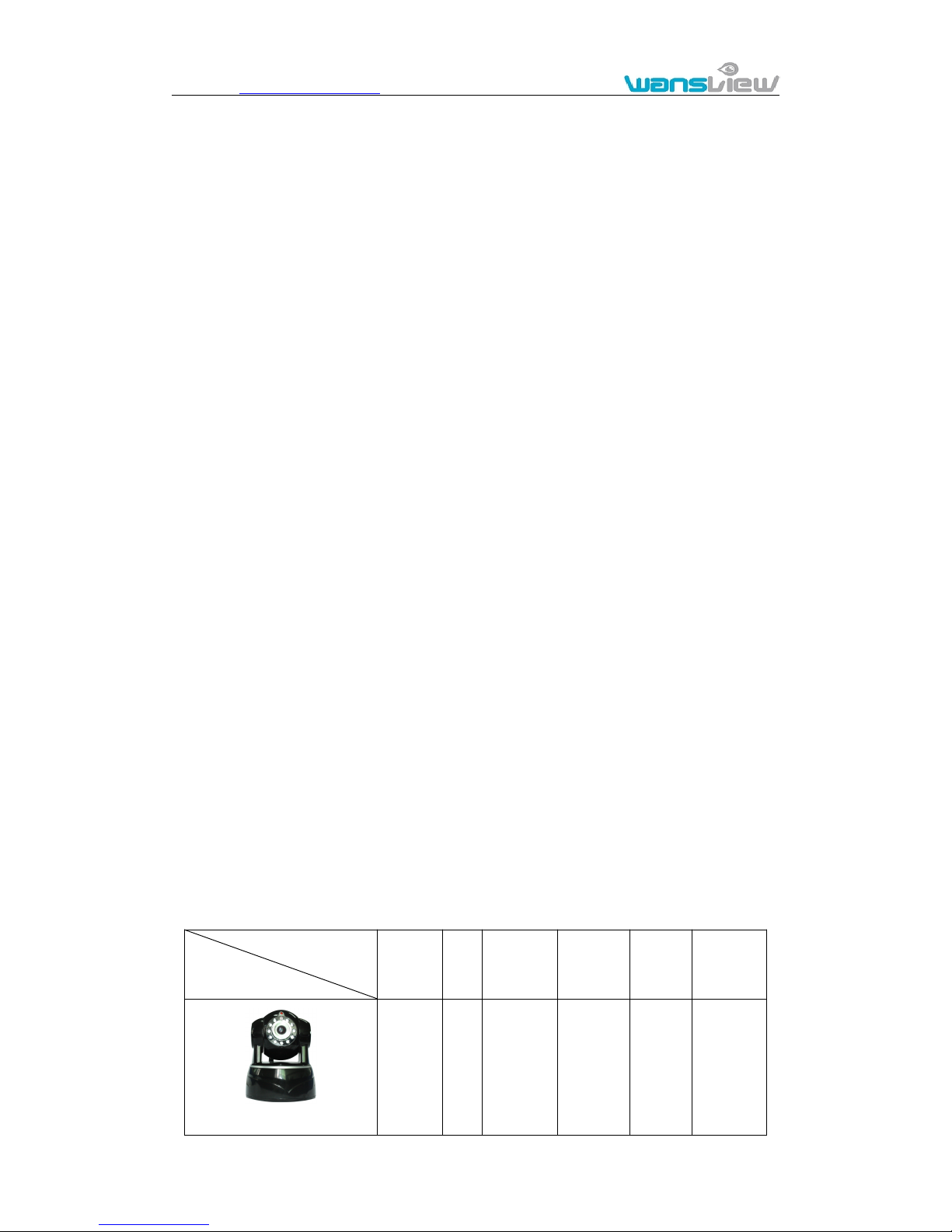
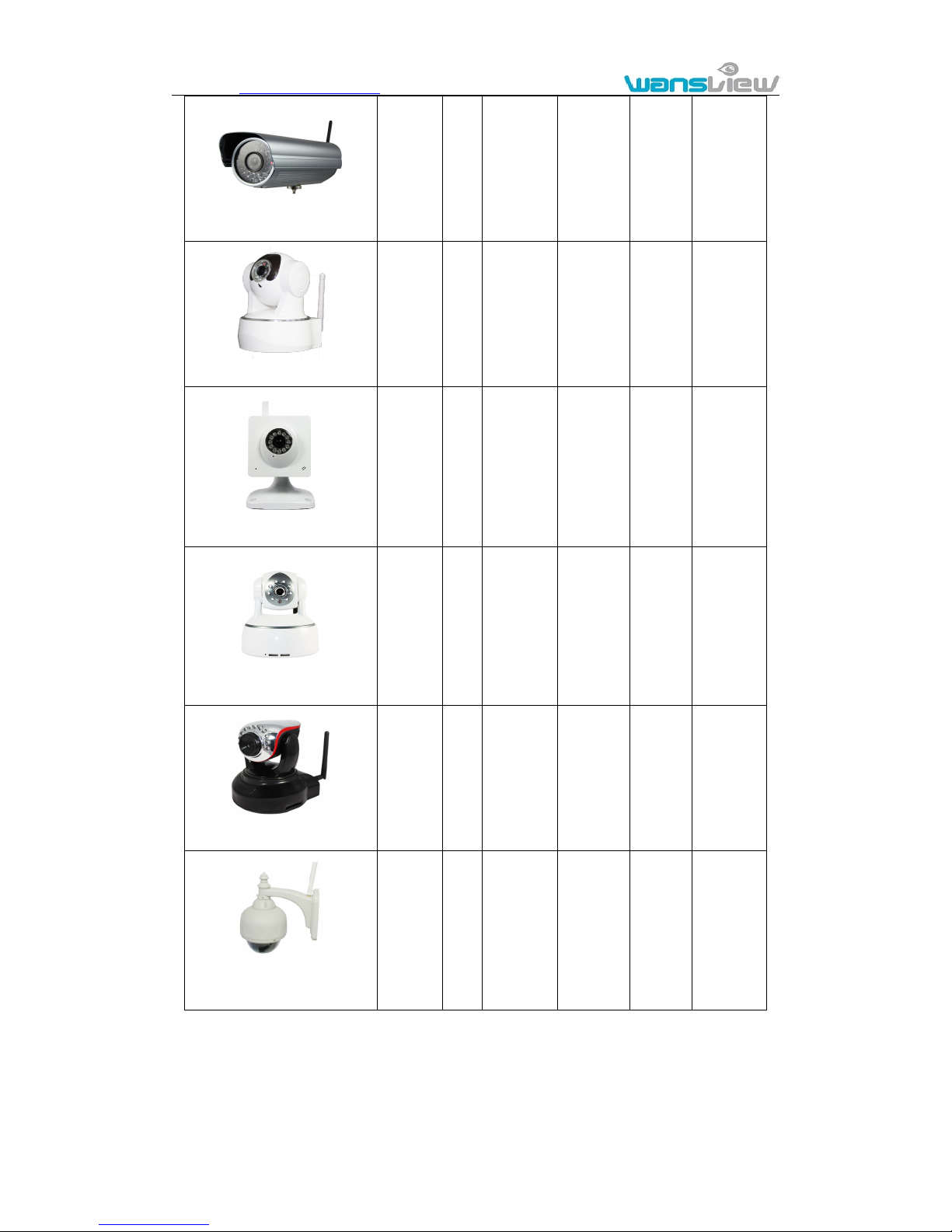
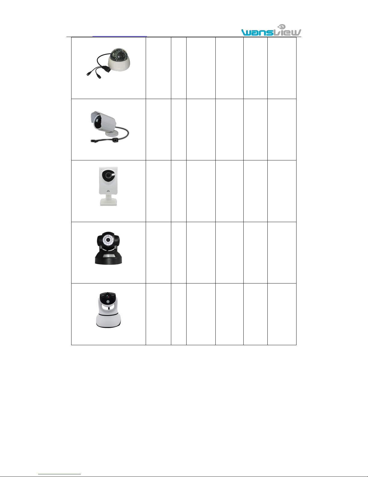
1.2. Package for typical production
Accessory
Type
Power
adaptor
CD
Network
Cable
Bracket
Stand
of
plastic
Antenna
NCM620W
5V
√√√√√
Page 6
http://www.wansview.com
6
NCM621W
12V√√√√
√
NCM622W
5V√√√√
√
NCM623W
5V√√√√
-
NCM624W
5V√√√√
√
NCM625W
5V√√√√
√
NCM626W
12V√√-√
√
Page 7
http://www.wansview.com
7
NCM627W
12V√√-√
-
NCM628W
12V√√√√
√
NCM629W
5V√√√√
-
NCM630W
5V√√√√
-
NCM631W
5V√√√√
√
Notice:
If you choose IP camera with wireless function, so it includes wifi module inside
the camera and antenna in package.
Please check carefully if all listed items are included in the package, if anything
missing, please contact vendor in time.
Page 8
http://www.wansview.com
8
2. Installation and Operation Guide
2.1. View video by mobile phone software
You need to download and install iSmartviewPro mobile phone client software from
attached CD, and then scan QR code on the camera body to add camera for viewing video, for
detail, please see “Product Quick Application Guide”.
2.2. View video by wired connection in LAN
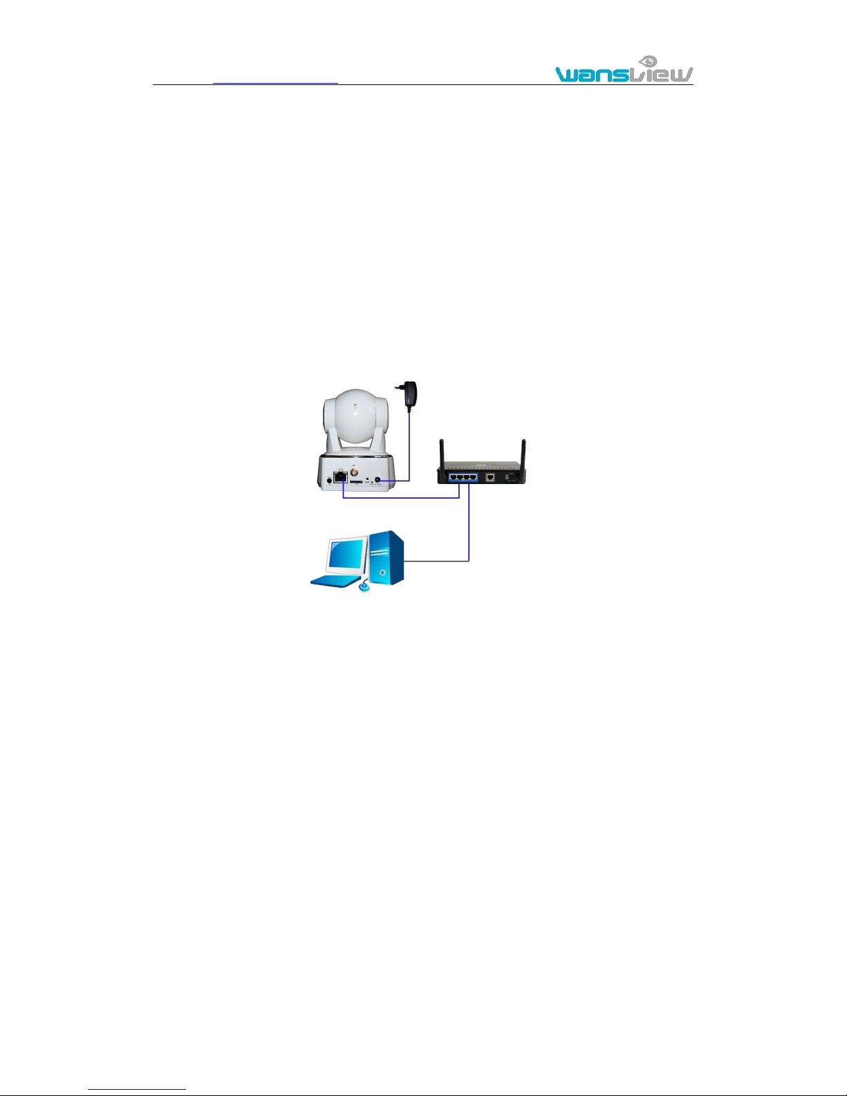
Power on the IP camera(please check carefully the voltage of power adaptor, don’t
insert incorrect power, otherwise it will be damaged), connect IP camera to router by
network cable and connect computer to the same router, example of figure 1.
Figure 1
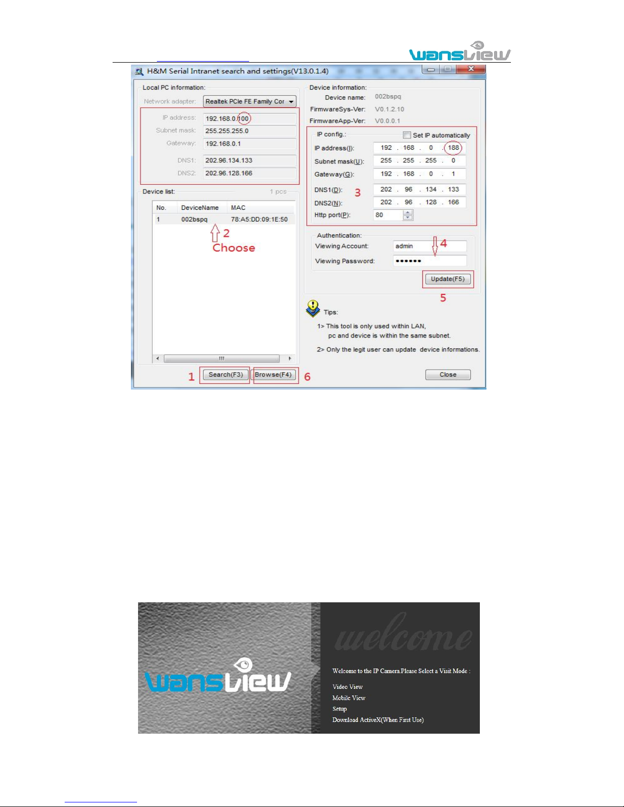
Insert attached CD to computer driver, double click “H&MSearch_en.exe” in the CD,
will pop up the interface as figure 2, please operate as the following steps:
Router
LAN Computer
IPcamera
Page 9
http://www.wansview.com
9
Figure 2
1) Click “Search”(Please make sure your firewall will not block up the item to be
searched)
2) Choose a camera;
3) Change the ip address of the ip camera according to the information in the red
frame on the left. The numbers in the red circle should not be the same. The
Http port should be a number between 80~65535;
4) Enter user name and password for the device, the default is “admin” and
“123456”;
5) Click “update”;
6) After updating successfully, click “Search (F3)”, choose the device again and
click “Browse (F4)”. Then you can run the web browser, enter user name and
password and login IP camera to view the video, example of figure 3.(please
use IE browser at first time)
Page 10
http://www.wansview.com
10
Figure 3
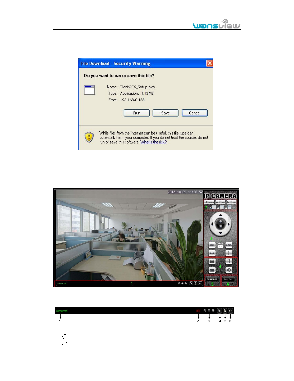
Notice: Need to download ActiveX when first use, click “download ActiveX( when first
use)” in figure 3, will display prompt as figure 4, click ‘run’ will download and install the
ActiveX automatically.
Figure 4
Tips: You can hold on reset button on the camera for 10 seconds to restore factory
default if you forget user name and password, or not sure the device parameters.
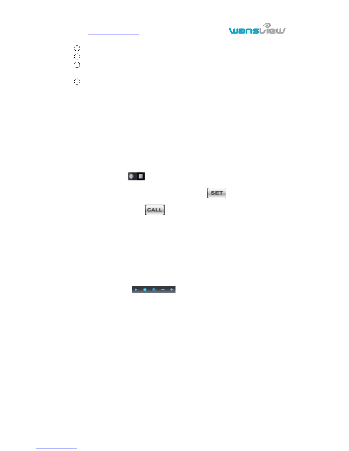
Click “Video View” in figure 3 to access video interface as below.
1) Status bar
Figure 4-1
1 Display connection status;
2 Display record status: if click “Record”, it will show “REC” which stands for
Page 11
http://www.wansview.com
11
recording; click record button again, it will stop;
3 Zoom out, zoom in and restore digital zoom;
4 Set saving file path: set the location for recording and capturing file storage;
5 Talk button: Click this button to hear what the person at the side of computer
talks. Click it again, it will stop playing;
6 Audio monitor button: Click this button to hear what people talking about at the
side of IP Cameras,
2) Choose video stream
You can choose primary stream or second stream, third stream to view the video.
Recommend to view by primary stream in LAN, by second stream in WAN and by third
stream in mobile phone.
You can view the video by four, nine pictures in same screen, but need to set the camera
in 3.6.6 multiple setting.
3) PTZ control
If the camera supports PTZ function, you can click up, down, left, right arrow to control
the camera moving, click button to center and stop the camera.
When you set camera to a preset position, and then click ‘ , after the camera is
changed to other direction, click can move the camera to the position you have
set.
4) Snap /record / SD card/playback
Click “Snap” button, to save the picture to the specified file.
Click “Record” button to start record. Click again to stop record.
Click “Check TF/SD card” can browse the files in the SD card (If the SD card
already inside the camera), you can select file to download it;
Click “Playback” button, it will show a player which can play the record video.
For these buttons means: play; stop; open video file; slow
play; quick play.
2.3. View video by WiFi connection in LAN
After finishing the wired connection as chapter 2.2, you can connect the camera by WiFi.
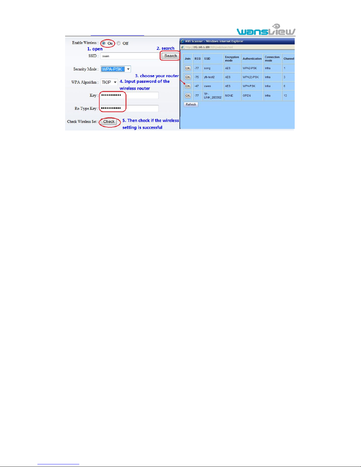
Login camera in wired connection and enter wifi setting, and then operate as the
following step, example of figure 5.
Page 12
http://www.wansview.com
12
Figure 5
Select ‘On’ and click ‘Search’, and then select wireless router in pop up menu, click ‘OK’
and enter its password, click ‘apply’ to save the wireless settings. And you can click
‘check’ to check if the wireless setting is successful. After setting successfully, please pull
out network cable and reboot the camera to use the wireless connection to view video.
Because the camera supports WPS/QSS, so you can set wireless by simple way as
below.
1) Please confirm if the router connected to camera supports WPS/QSS (you can
check user manual of the router or get the support from router factory);
2) Press WPS/QSS button on the router, it will launch the function.
3) Press and hold on reset button for 2~5 seconds after it ran normally ( not need
connect cable), it will launch the WPS/QSS function, then match the setting with the
router, the status LED always on when it was matching, and it will flash after
matching successfully.
4) Unplug power adaptor and reboot the camera, then you can use the wireless
connect function.
Note: The camera will automatically stop the function when the matching is unsuccessful
after continuing 50 seconds. Due to different kinds of the router, we don’t sure our
camera can be connected to all routers successfully.
2.4. View video in internet
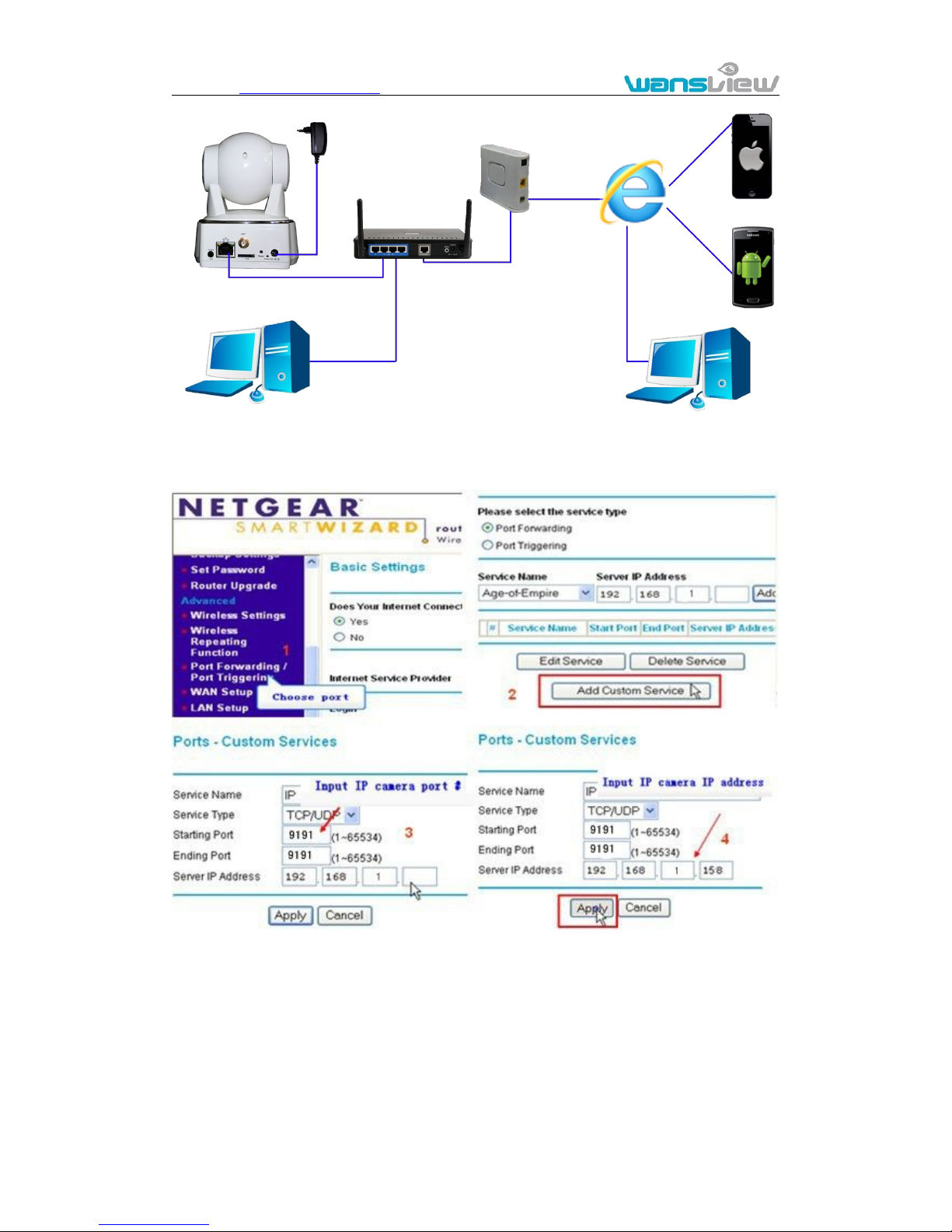
You should connect your internal network to the internet first and configure port
forwarding, consult your router’s manual for further details, as figure 6.
Page 13
http://www.wansview.com
13
Figure 6
For example: operation step of port forwarding as figure 7.
Figure 7
1) Please go to the setting interface of Router, and choose “Port Forwarding”;
2) Choose “Add custom Service” ;
3) Input IP camera http port;
4) Input LAN IP Address of the camera, click “Apply” (port number and IP address as
you set in figure 2)
After finishing the port forwarding, you can use WAN IP address of router and http port of
IP camera
Computer
Computer
Router
ADSL
Internet
IOS
Android
Page 14
http://www.wansview.com
14
camera to visit the camera by remote computer as figure 6.
Notice: because the routers are different, so the interface and setting method of router
are also different, how to do the port forwarding for various routers, please refer to the
user manual of your router or consult with router manufacturer.
2.5. View Video by PC client software
You need to download and install iSmartViewPro PC client software from attached CD, and then
add camera to view live video. For detail, please see the “User manual for iSmartViewPro”.
2.6. View Video by other way
2.6.1. Other Web Browser
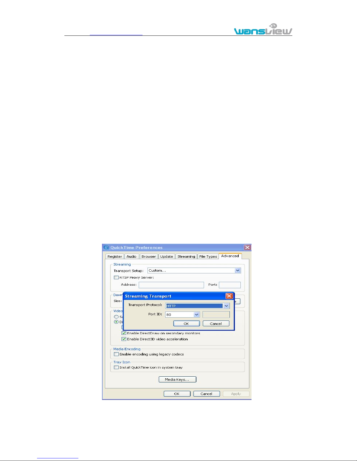
In the Windows OS, for using browser with IE kernel, user must download the ActiveX.
While for Safari and Firefox browsers, please download “QuickTime” plug-in and install it
to access the IP camera. After installation, please run the QuickTime program to access
the QuickTime Preferences dialog box from Edit Menu, example as below. Click
“Advanced”, select “custom.” in the Transport Setup. It pops up the Streaming Transport
dialog box. Please select “HTTP” for transport protocol and “80” as port ID, click “ok”,
and then return to Transport Setup to change “Custom..” to “Auto”. Finally, click “ok” at
the bottom. After finishing these settings, run the Firefox or Safari browser to view the
video.
In Mac computer, the Quicktime is installed by default, so the user simply accesses
setting tool folder at application folder and run the command program, enter command
Page 15

http://www.wansview.com
15
by command line mode:
qtdefaults write TransportSettings HTTP 80
And then run the Safari browser to view the video.
Note: Please select the G.711 audio code format for hearing sound in Quicktime plug-in.
2.6.2. Other common software
As the device supports RTSP protocol, you can use VLC player to play IP Camera video.
It is compatible with VLC 1.1.12 version or above. Please use below URL to visit:
rtsp://ip:port/11 (View the video by first stream)
rtsp://ip:port/12 (View video by second stream)
rtsp://ip:port/13 (View video by third stream)
The port is RTSP port; please refer to the settings of Figure 13.
3. All settings
3.1. Video setting
In the setting, you can adjust the video, audio and image setting according to actual
environment for getting best effect.
Page 16
http://www.wansview.com
16
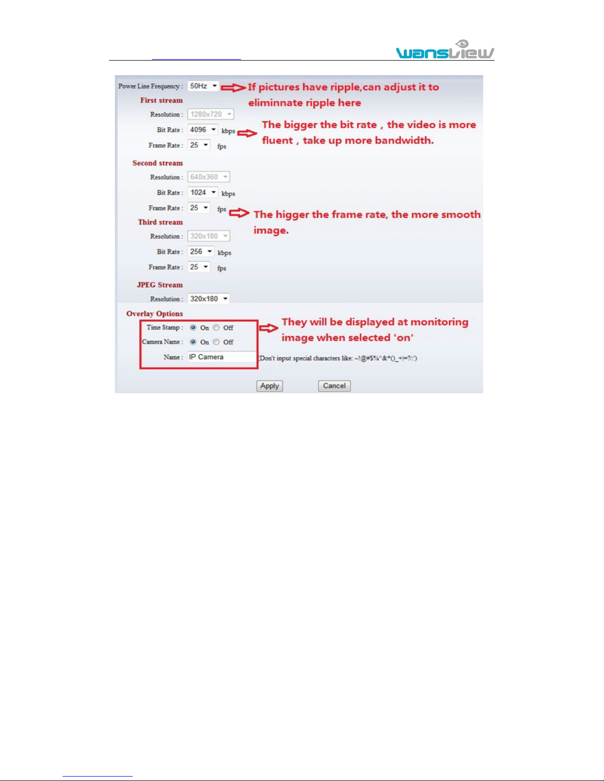
3.1.1. Video parameters
Figure 10
JPEG stream is for some views by non windows platform, for example, click ‘mobile view’
in first page, it will transmit JPEG stream actually.
Page 17
http://www.wansview.com
17
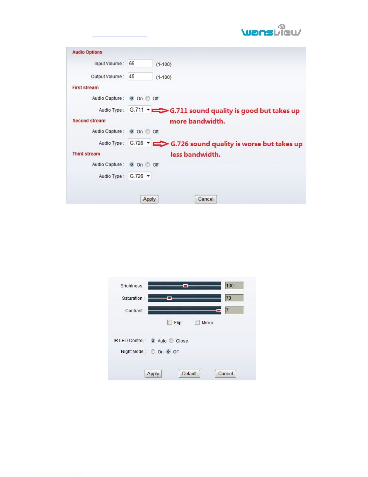
3.1.2. Audio parameters
Figure 11
The camera supports G.711 and G.726 audio encoding format. The sound of the G.711 is
better, but it occupies more bandwidth. If you click “On” of the audio capture, so it will
transmit audio in corresponding video stream. Please open the audio here, should you
hear the sound when clicking audio play button in figure 4-1.
3.1.3. Image parameters
Figure 12
You can select “close” to disable IR LED when you don’t need it. At night mode, it will cut
frame rate automatically to enhance night vision at night when you select “on”.
Page 18
http://www.wansview.com
18
3.2. Web setting
3.2.1. Basic web setting
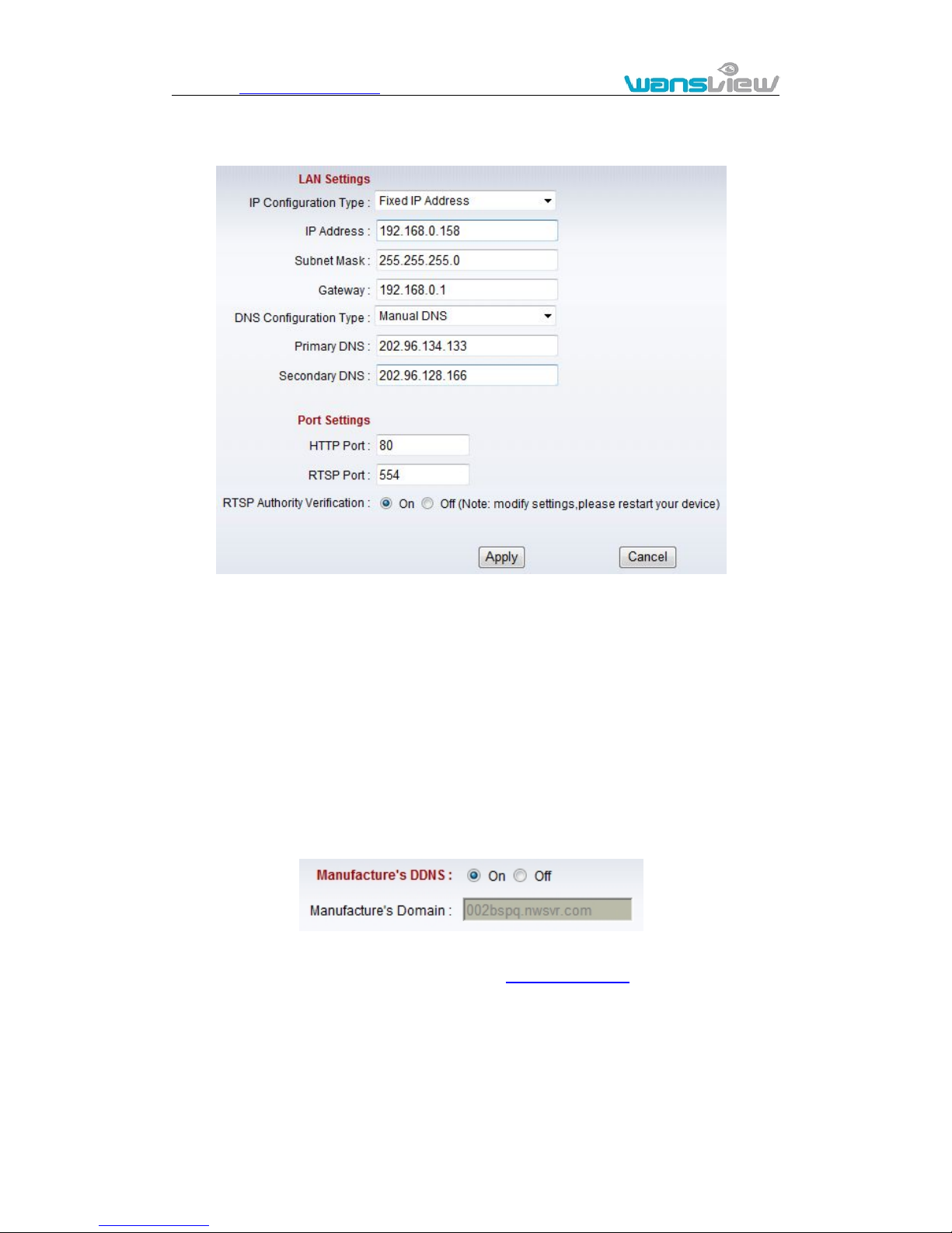
Figure 13
The cameras support RTSP protocol, if select “on” of “RTSP authority verification”, you
need to enter user name and password when invoke video by RTSP protocol.
3.2.2. WIFI setting
Please refer to chapter 2.3.
3.2.3. WAN access setting
In chapter 2.3, you have known how to do port forwarding. After the success of the port
forwarding, you can also visit camera by DDNS. The manufacturer has established a
DDNS system, and allotted a DDNS to every device, the user can view it from remote PC,
example of figure 14.
Figure 14
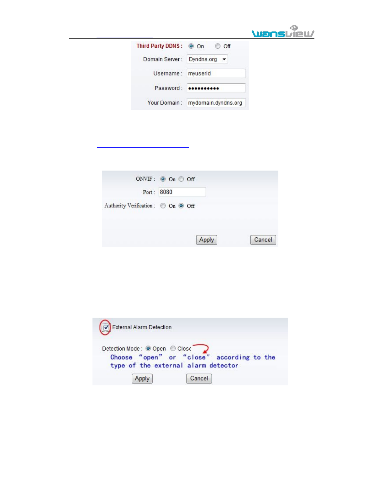
User can also use third party DDNS, such as www.dyndns.com. User applies a free
domain name from this website and fills the info into below blanks (Figure 15) and saves
the settings. Then the domain name can be used.
Page 19
http://www.wansview.com
19
Figure 15
Notice: Using the third party DDNS, if the http port is not 80, the port number should be
adding to the domain name with colon.
Example: http://mydomain.dyndns.org:81.
3.2.4. ONVIF setting
Figure 16
The camera supports ONVIF protocol, so it can be interconnected with other factory
camera with ONVIF.
Tips: The device supports ONVIF 2.0.1 at present.
3.3. Alarm setting
3.3.1. External Alarm Input
Figure 17
The camera should have external alarm input port for enable this functions. Connect
external alarm detector to the input port, the detector will output switching signal when it
detects any abnormal, input port of the camera will detect the level change, so it will
detect the alarm, therefore the detector should be switching sensor (same as switch)
Page 20
http://www.wansview.com
20
3.3.2. Motion Detection Setting
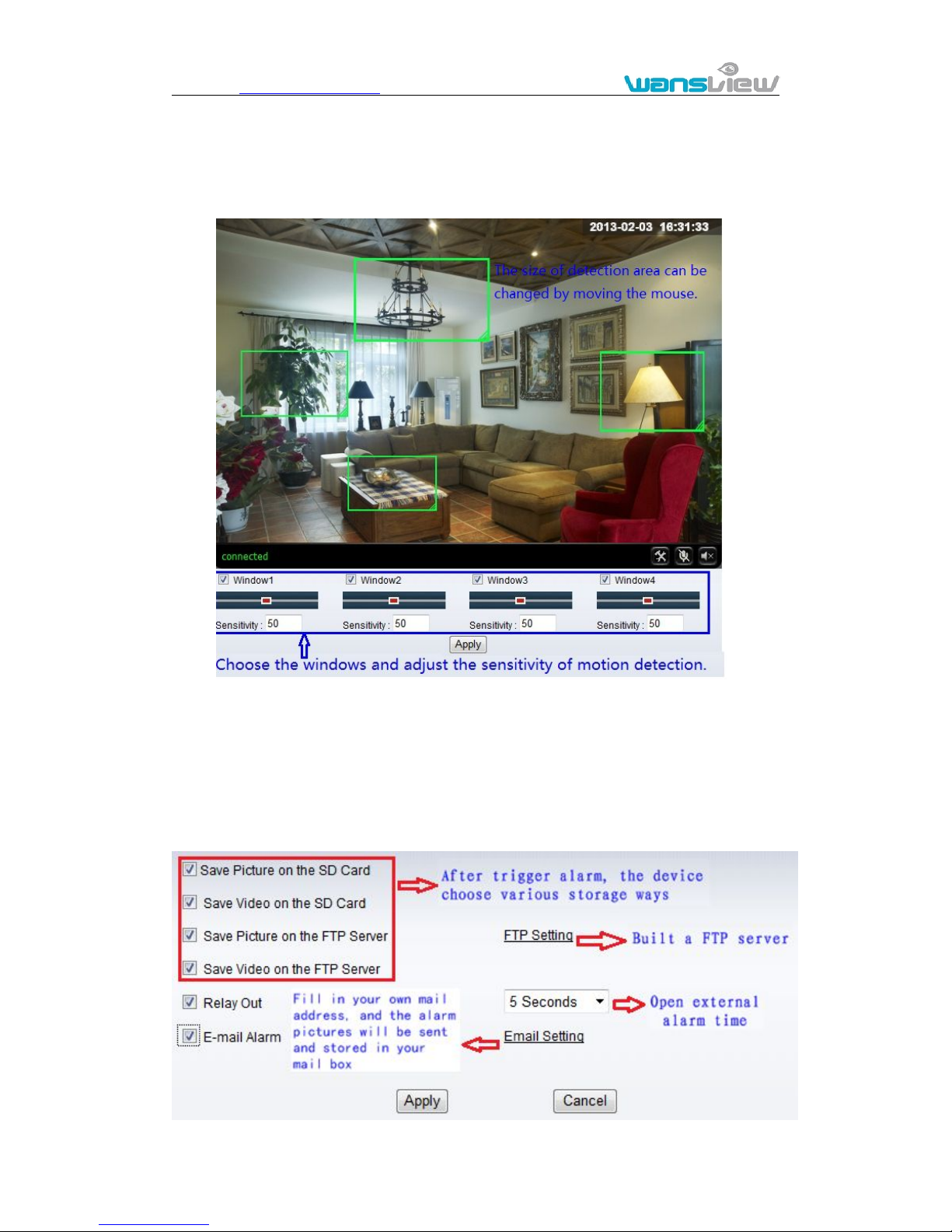
Click SYSTEM SET->>ALARM->>Motion Detection to access setting interface as figure 18,
you can set up detect window here, tick a window, the corresponding green frame of motion
detection window is displayed, you can tick four windows maximum for motion detection area
as below.
Figure 18
Please click “apply” after finishing the settings, and motion detection takes effect. The
higher value, the higher sensitivity. The camera will trigger corresponding alarm when
any change occurs in the detection area.
3.3.3. Alarm mode setting
After camera detects any change, it will alarm as several mode, example of figure 18.
Page 21
http://www.wansview.com
21
Figure 19
3.3.4. Alarm time setting
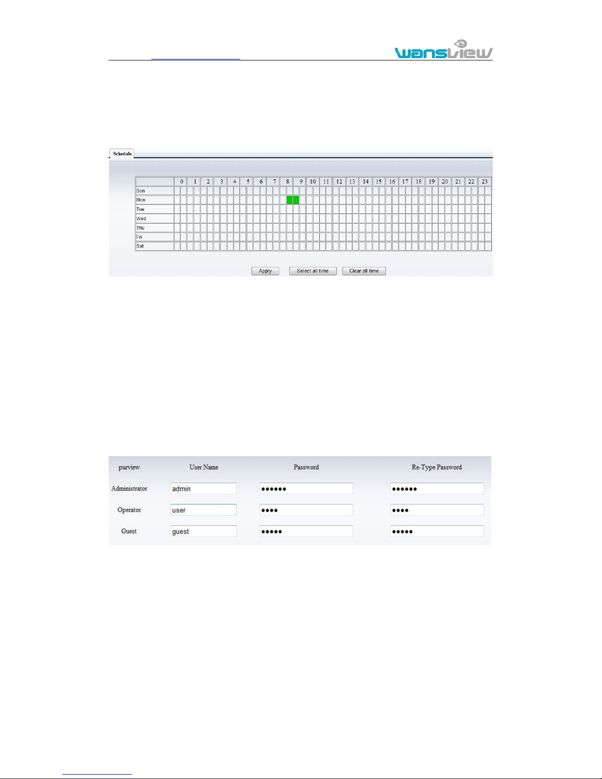
Click SYSTEM SET->> ALARM->>Schedule to access it.
Figure 20
The device will trigger the alarm only during the scheduled time period, you can select
the scheduled time according to your request. Example of figure 20, set armed time from
Mon 8:30 to 9:30, you only need to click the corresponding time block to set them, the
time block will become green when you selected.
Note: Please make sure your system time is correct before you set the alarm time period.
Please refer to chapter 3.5.2 to set system time.
3.4. Advance setting
3.4.1. User management
Click SYSTEM SET->>ADVANCED->>User to access it.
Figure 21
There are 3 levels of user authorization in it.
Administrator: “admin” has the highest authority. It can do any settings. The factory
default password: 123456.
User: user can only operate the device but can’t do any settings. The default
password is user.
Guest: User can view the video, but can’t operate the device. The default password
is guest.
Note: Please change these 3 level passwords when your first use to ensure your safety.
Page 22
http://www.wansview.com
22
3.4.2. Auto Capture Setting
Click SYSTEM SET->>ADVANCED->> Auto Capture to access it.
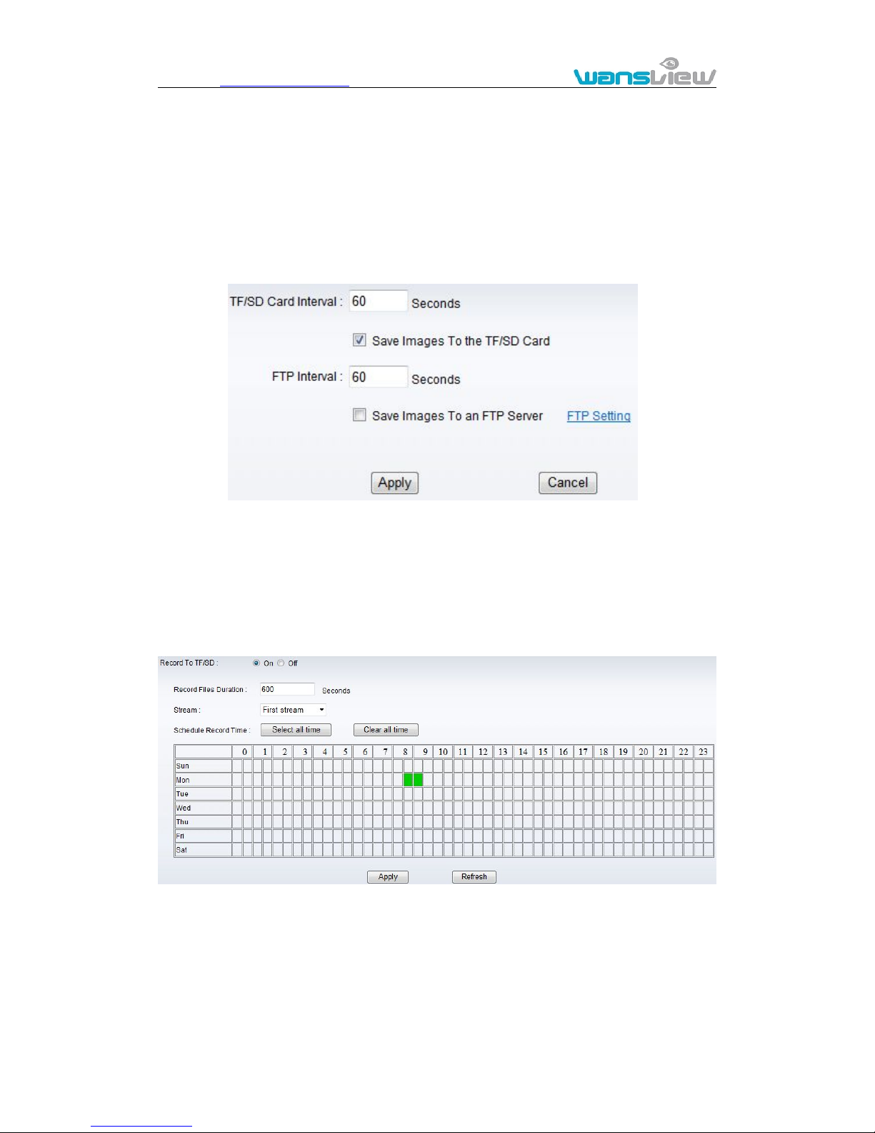
Figure 22
Tick “Save Images to the TF/SD card”, the snap pictures will be stored into SD card
during the setting time.
3.4.3. Timer recording
Click SYSTEM SET->>ADVANCED->> Record to TF/SD to access it.
Figure 23
For example, set up recording time from Mon 8:30 to 9:30 as figure 23.
Tips:
Please insert TF/SD card when the device power off, to avoid damage the TF/SD
card or not to read it from the device.
3.4.4. E-mail Setting
Click SYSTEM SET->>ADVANCED->>Email to access it.
Page 23
http://www.wansview.com
23
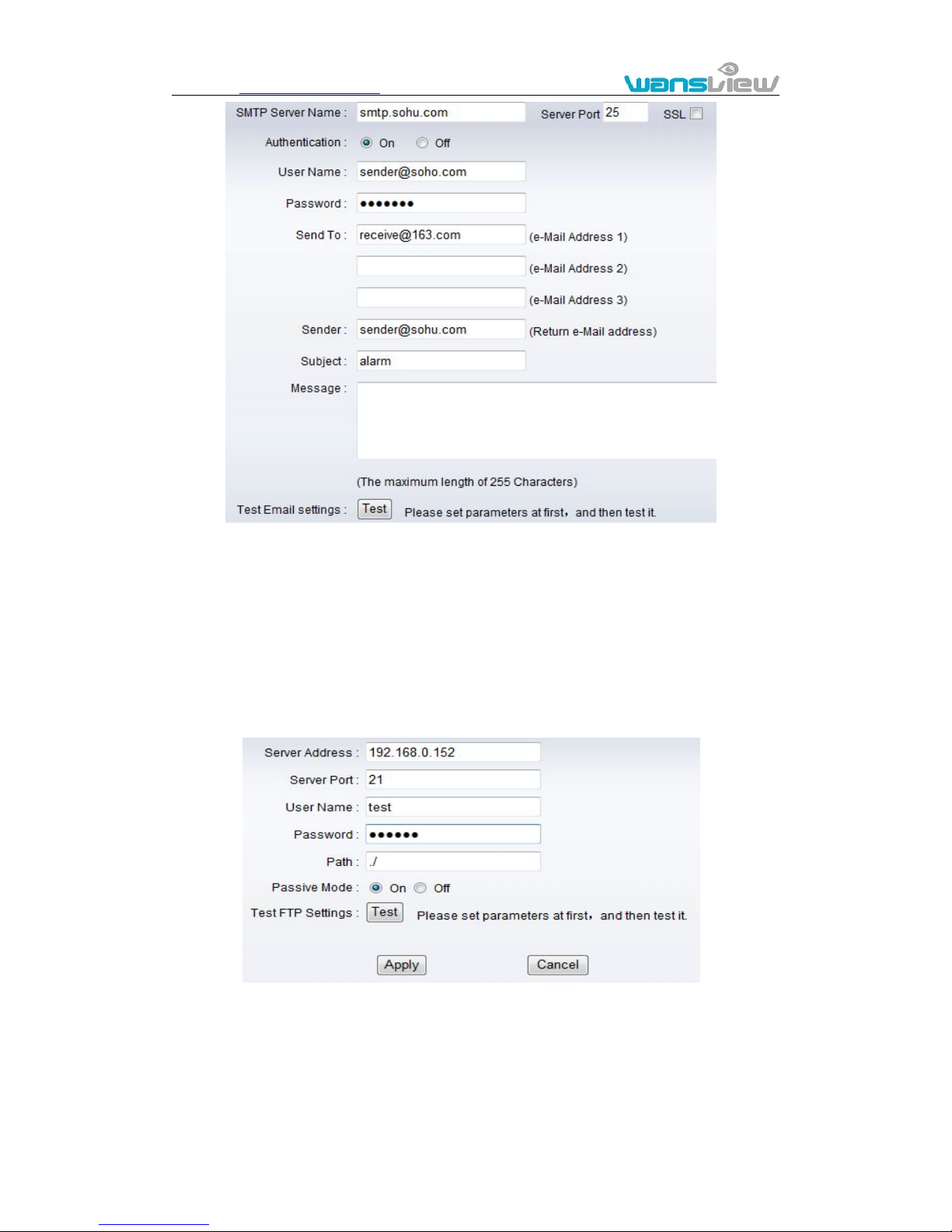
Figure 24
The SMTP server name: It is mailbox server, for example of SOHU mailbox, it is
“smtp.sohu.com”. Please fill all blanks which we filled above in figure 24 as example.
Otherwise, the settings will fail.
Please click “Test” to test if the E-mail setting is successful.
3.4.5. FTP setting
Click SYSTEM SET->>ADVANCED->>FTP to access it.
Figure 25
Before to use FTP function, please get the following ready.
1) FTP user name and password
2) FTP storage space and the authority
3) Create sub-category to store the video or pictures.
Notice: The password should not be special character; otherwise the camera can’t
Page 24
http://www.wansview.com
24
identify it.
3.4.6. Multiple settings
Click SYSTEM SET->>ADVANCED->>Multiple Settings to access it.
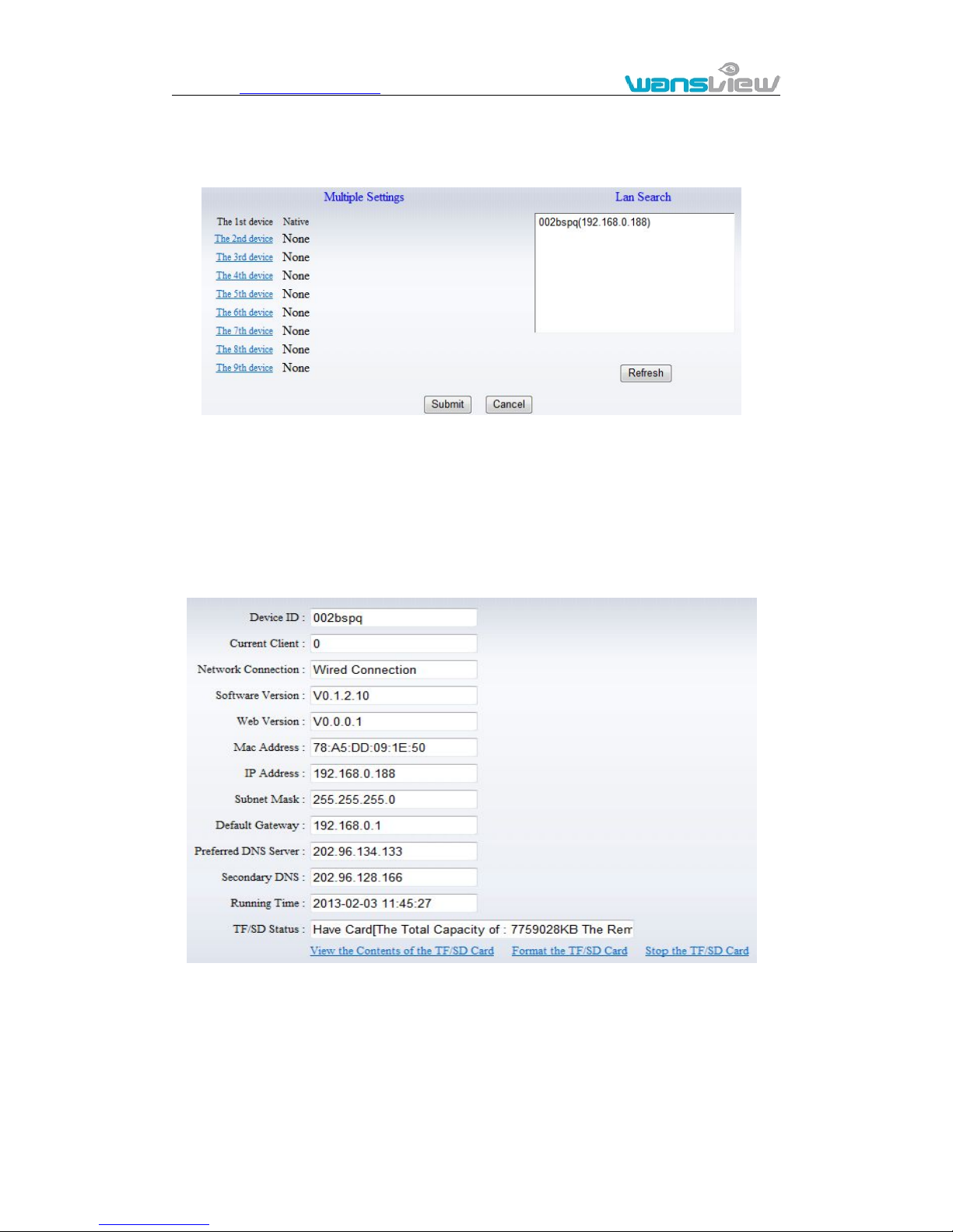
Figure 26
Please set multiple devices here first to view 4 or 9 split screen at chapter 3.1 browse
interface.
3.5. System setting
3.5.1. Device information
Click SYSTEM SET->>SYSTEM->>Device Information to access it.
Figure 27
SD status shows the free capacity if SD card is installed.
Notice: the device supports max 32G SD card. Please format the SD card to FAT32
before use the card on camera. Please check if the SD Card matches the camera or not
before purchasing the SD Card.
Page 25
http://www.wansview.com
25
3.5.2. Date and time setting
Click SYSTEM SET->>SYSTEM->>Time Settings to access it.
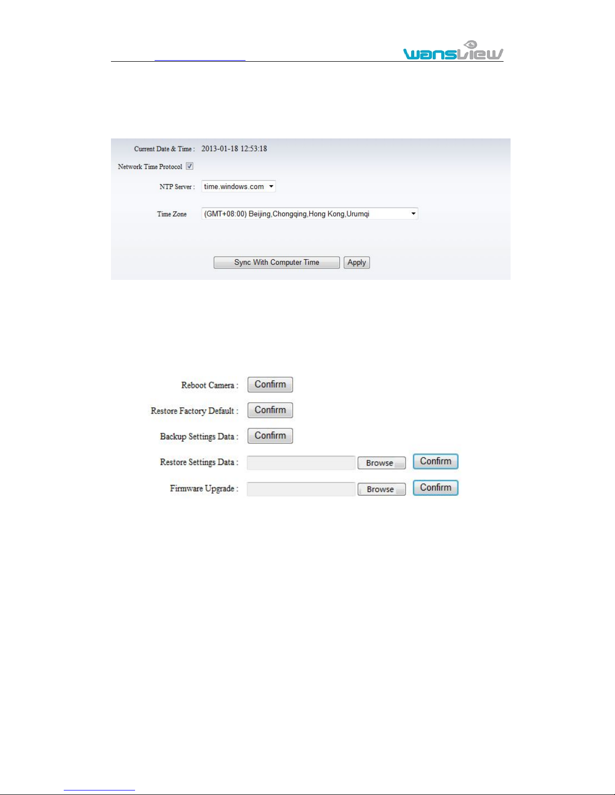
Figure 28
Example of figure 28, please select the time zone at first and then select a NTP server
and obtain time from network time server.
3.5.3. Initialize setting
Click SYSTEM SET->>SYSTEM->>Initialize to access it.
Figure 29
If you click “Confirm” of Backup setting data, the camera will create a file, you can store it
to your computer, and you can directly call this file to restore the settings. The function
helps to manage the cameras and no need to do all the settings again.
The firmware upgrade is for updating system firmware and web UI.
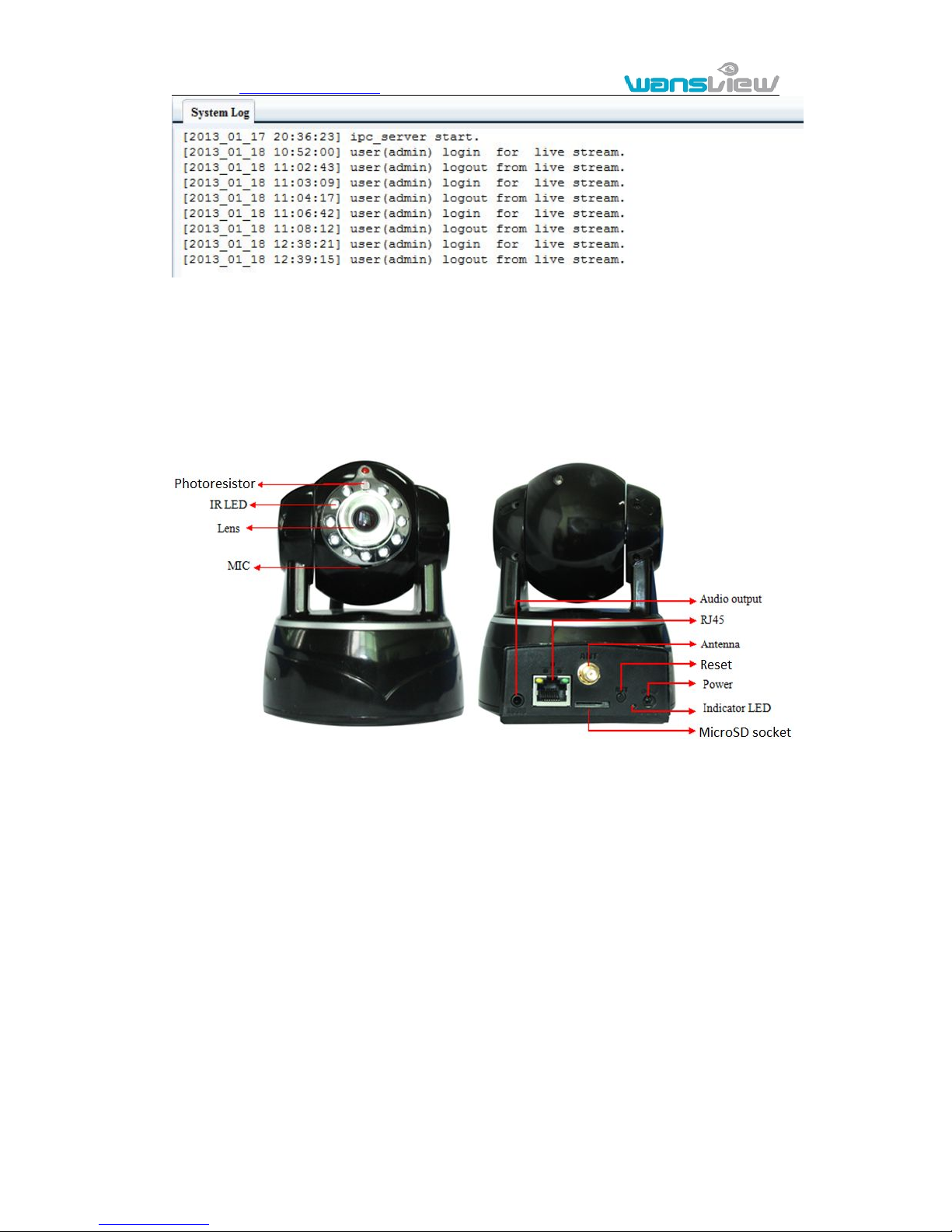
3.5.4. System Log
Click SYSTEM SET->>SYSTEM->>System Log to access it.
Page 26
http://www.wansview.com
26
Figure 30
4. Product family for SmartP2P camera
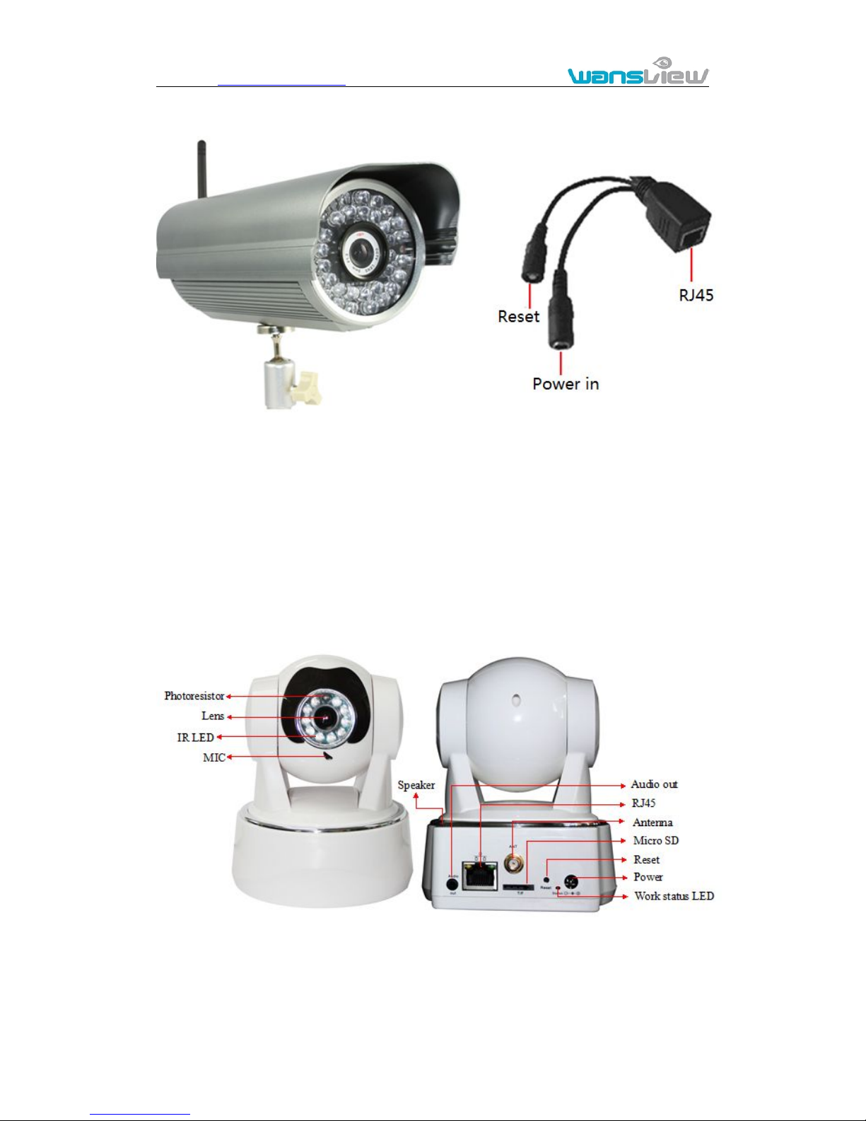
4.1. HD PTZ Camera NCM620W
Figure 31
The camera features:
Max. resolution is 720P, support two way intercom, build in MIC;
Build in WIFI module, support 802.11b/g/n, easy for connecting wireless router;
Support rotate 290° horizontally and 120° vertically;
Build in IR-CUT, 3.6mm lens;
11 pcs IR LED, up to 8 meter night vision;
Micro SD card socket for recording storage
Work status LED indicate:
Flash normally (1 time per second) means the device runs normally, it means
the camera was connected to wired network
Always on, it means the camera is searching WPS
Flash very fast (3 times per second) it means the camera was connected to
wireless network
Page 27
http://www.wansview.com
27
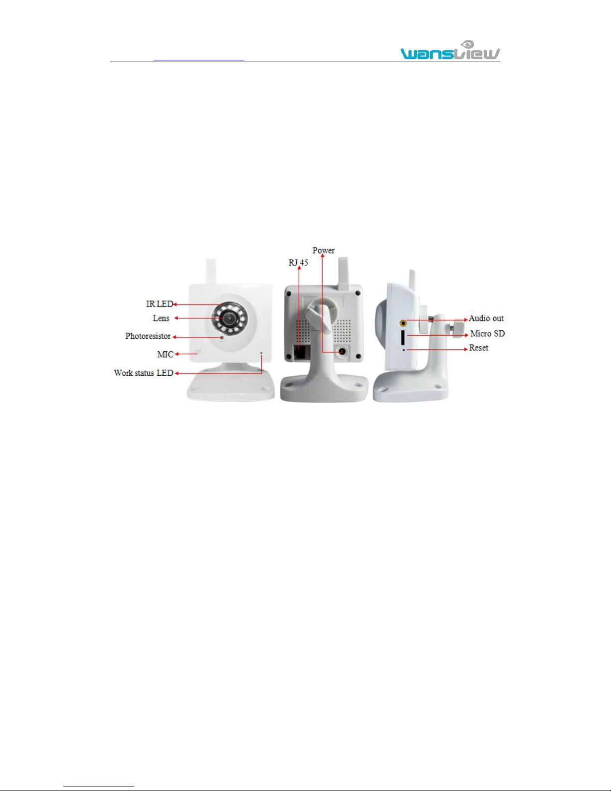
4.2. HD waterproof camera NCM621W
Figure 32
The camera features:
Max. resolution is 720P;
Build in WIFI module, support 802.11b/g/n, easy for connecting wireless router;
Build in IR-CUT, 8mm lens;
36pcs IR LED, up to 25 meter night vision;
Micro SD card socket for recording storage
Support waterproof level IP66 for outdoor use.
4.3. HD PTZ Camera NCM622W
Figure 36
The camera features:
5) Max. resolution is 720P, support two way intercom, build in MIC,and Speaker;
6) Build in WIFI module, support 802.11b/g/n, easy for connecting wireless router;
7) Support rotate 290° horizontally and 120° vertically;
Page 28
http://www.wansview.com
28
8) IR_CUT, 3.6mm lens;
9) 10 pcs IR LED, up to 6 meter night vision;
10) Micro SD card socket for recording storage
11) Work status LED indicate:
5) Flash normally (1 time per second) means the device runs normally, it means
the camera was connected to wired network
6) Always on, it means the camera is searching WPS
7) Flash very fast (3 times per second) it means the camera was connected to
wireless network
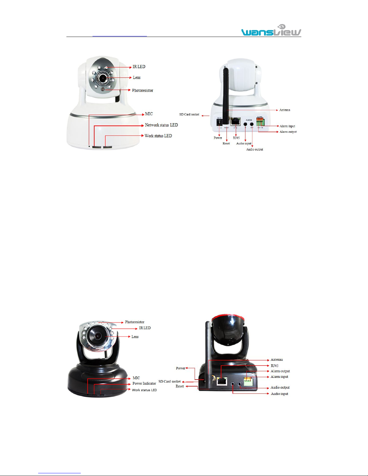
4.4. HD Cube Camera NCM623W
Figure 34
The camera features:
Max. resolution is 720P, support two way intercom, build in MIC;
Build in WIFI module, support 802.11b/g/n, easy for connecting wireless router;
Build in IR-CUT, 3.6mm lens;
12pcs IR LED, up to 8 meter night vision;
Built-in Micro SD card socket
Work status LED indicate:
Flash normally (1 time per second) means the device runs normally, it means
the camera was connected to wired network
Always on, it means the camera is searching WPS
Flash very fast (3 times per second) it means the camera was connected to
wireless network
Page 29
http://www.wansview.com
29
4.5. HD PTZ Camera NCM624W
Figure 35
The camera features:
Max. resolution is 720P, support two way intercom, build in MIC;
Build in WIFI module, support 802.11b/g/n, easy for connecting wireless router;
Support rotate 350° horizontally and 100° vertically;
Build in IR-CUT, 3.6mm lens;
8 pcs IR LED, up to 5 meter night vision;
Alarm in/out for external alarm system connection;
SD card socket for recording storage;
Work status LED indicate:
Flash normally (1 time per second) means the device runs normally, it means
the camera was connected to wired network
Always on, it means the camera is searching WPS
Flash very fast (3 times per second) it means the camera was connected to
wireless network
4.6. HD PTZ Camera NCM625W
Figure 36
The camera features:
Max. resolution is 720P, support two way intercom, build in MIC;
Build in WIFI module, support 802.11b/g/n, easy for connecting wireless router;
Page 30
http://www.wansview.com
30
Support rotate 340° horizontally and 90° vertically;
Build in IR-CUT, 3.6mm lens;
10 pcs IR LED, up to 6 meter night vision;
Alarm in/out for external alarm system connection;
SD card socket for recording storage;
Work status LED indicate:
Flash normally (1 time per second) means the device runs normally, it means
the camera was connected to wired network
Always on, it means the camera is searching WPS
Flash very fast (3 times per second) it means the camera was connected to
wireless network
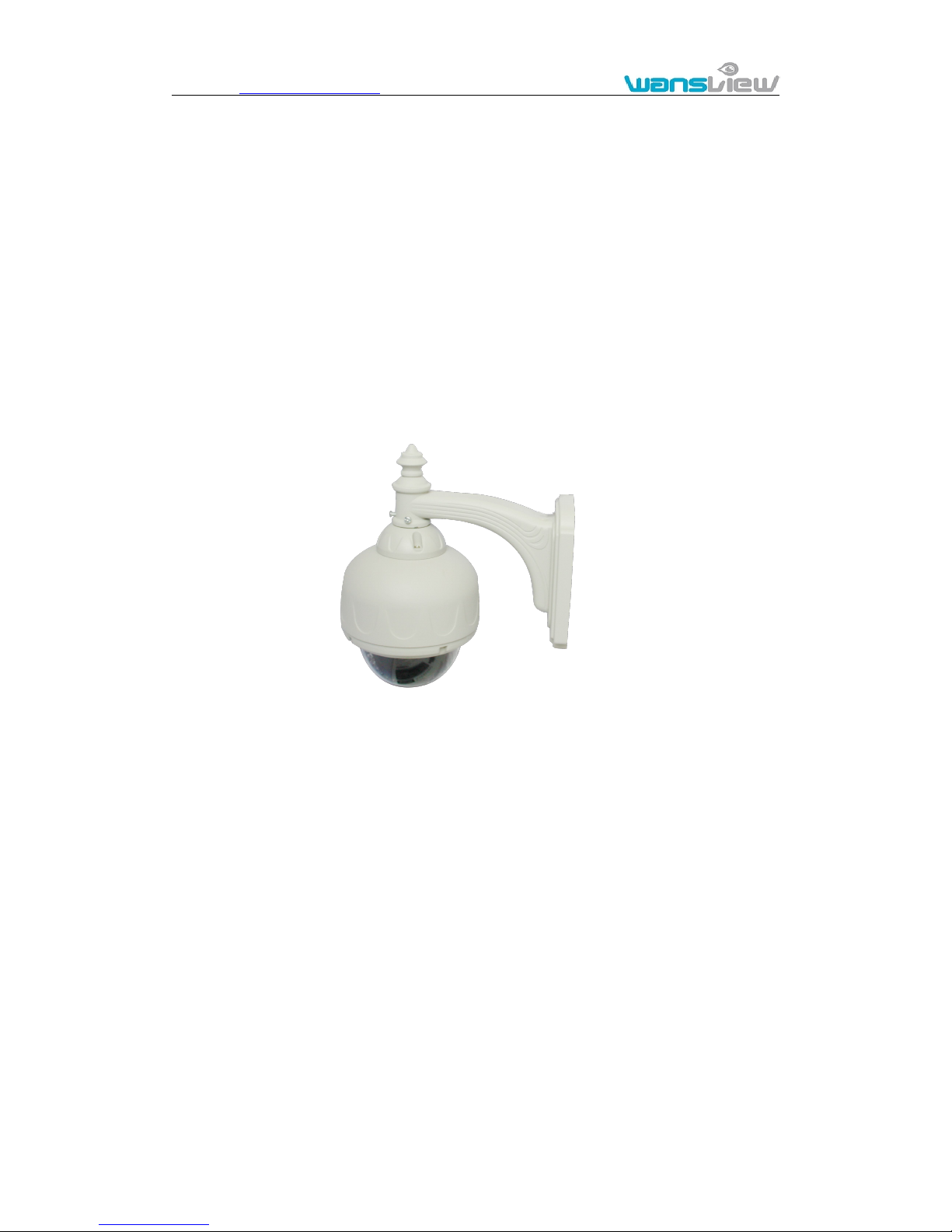
4.7. Outdoor HD Waterproof PTZ camera NCM626W
Figure 37
The camera features:
Max. resolution is 720P;
Build in WIFI module, support 802.11b/g/n, easy for connecting wireless router;
Support rotate 350° horizontally and 90° vertically;
Use IR-CUT filter, can change IR and color filter, 4mm Lens;
22pcs IR LED, up to 20 meters night vision;
Build in TF card slot, can insert TF card to it and record video to TF card when
detecting alarm;
Support waterproof level IP53 for outdoor use;
Page 31
http://www.wansview.com
31
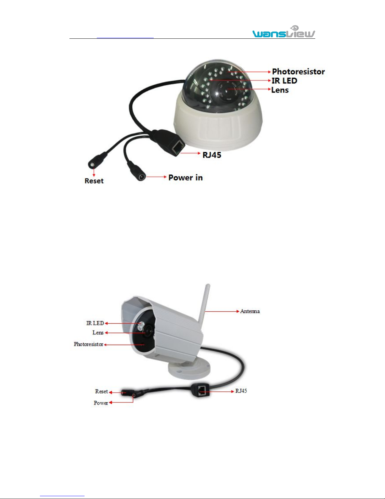
4.8. HD hemisphere Camera NCM627
Figure 38
The camera features:
Max. resolution is 720P;
Ceiling installation;
Use IR-CUT filter, can change IR and color filter, 4mm Lens;
Build in 30pcs IR LED, up to 25 meters night vision;
Support to power off IR LED manually.
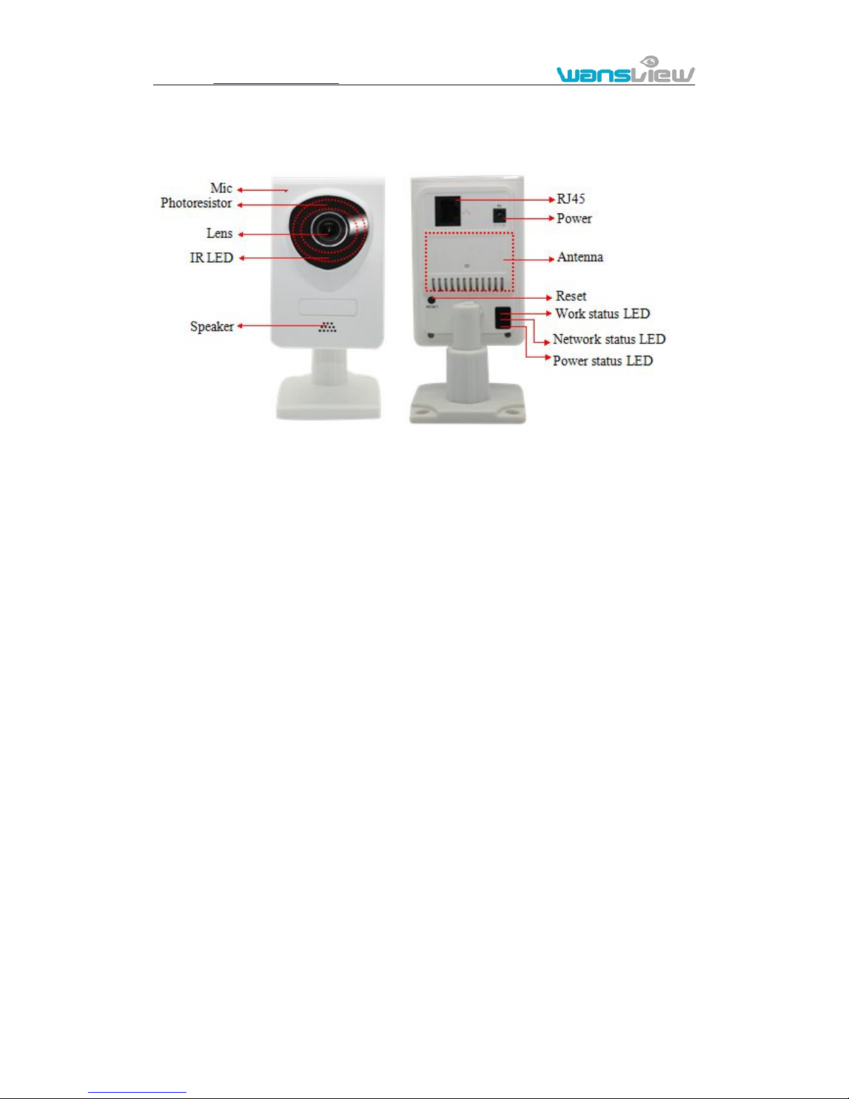
4.9. HD Waterproof Camera NCM628W
Figure 39
The camera features:
Max. resolution is 720P;
Build in IR-CUT, 3.6mm lens;
Build in 2pcs array IR LED, up to 15 meter night vision;
Page 32
http://www.wansview.com
32
Support waterproof level IP66 for outdoor use.
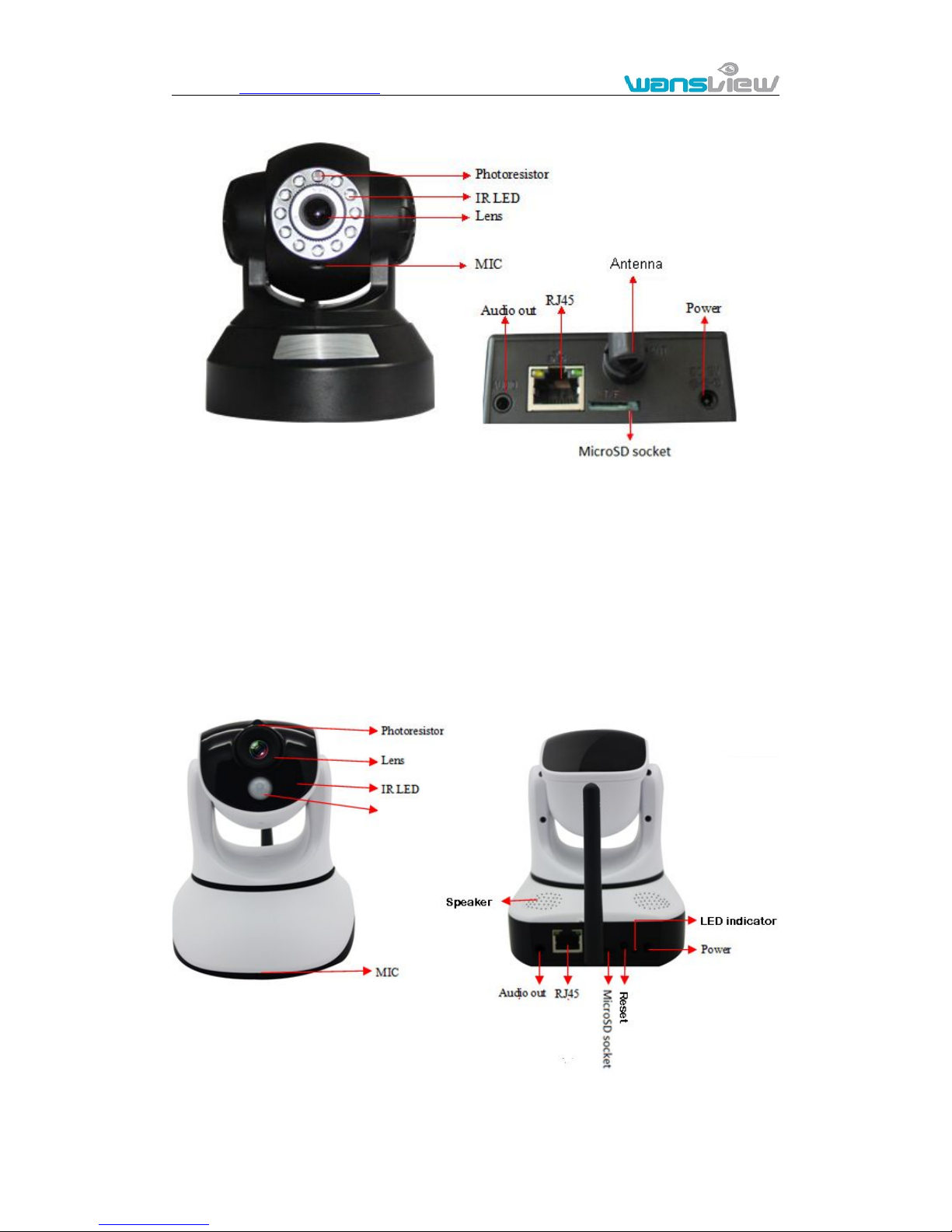
4.10. HD Cube Camera NCM629W
Figure 41
Max. resolution is 720P, support two way intercom, build in MIC and speaker;
Build in WIFI module, support 802.11b/g/n, easy for connecting wireless router;
Build in IR-CUT, 3.6mm lens;
8pcs IR LED, up to 5 meter night vision;
Built-in Micro SD card socket
Work status LED indicate:
Flash normally (1 time per second) means the device runs normally, it means
the camera was connected to wired network
Always on, it means the camera is searching WPS
Flash very fast (3 times per second) it means the camera was connected to
wireless network
Page 33
http://www.wansview.com
33
4.11. HD PTZ Camera NCM630W
Figure 42
Max. resolution is 720P, support two way intercom, build in MIC and audio out;
Build in WIFI module, support 802.11b/g/n, easy for connecting wireless router;
Build in IR-CUT, 3.6mm lens;
11pcs IR LED, up to 8 meters night vision.
Build in TF card slot, can insert TF card to it and record video to TF card when
detecting alarm.
Note:the reset button is placed on the bottom of device.
4.12. HD PTZ Camera NCM631W
Figure 43
Page 34

http://www.wansview.com
34
The camera features:
Max. resolution is 720P, support two way intercom, build in MIC and Speaker;
Build in WIFI module, support 802.11b/g/n, easy for connecting wireless router;
Build in PIR sensor, support motion detection;
Support rotate 350° horizontally and 90° vertically;
IR_CUT, 3.6mm lens;
12 pcs IR LED, up to 8meter night vision;
Micro SD card socket for recording storage
Work status LED indicate:
Flash normally (1 time per second) means the device runs normally, it means
the camera was connected to wired network
Always on, it means the camera is searching WPS
Flash very fast (3 times per second) it means the camera was connected to
wireless network
Statement:
1. This manual may be different with your using camera, if you have any questions
of the manual, please contact our technical support.
2. This manual will be updated periodically; the company reserved the right
without prior notice.
 Loading...