

Wanner International Hydra-Cell G-25, Hydra-Cell H-25 Installation Service
W0452
Installation & Service
GH25-991-UK00B
Models: G-25, H-25
Wanner International Ltd
8/9 Fleet Business Park
Sandy Lane, Church Cr,
Hants, GU52-8BF
Telephone: +44 (0) 1252 816847
Fax: +44 (0) 1252 629242
Email: sales@wannerint.com

G/H-25 Contents
Page
Specifications ..........................................................................2
Dimensions .............................................................................4
Installation ...............................................................................5
Maintenance ..........................................................................11
Service (Fluid End) ...............................................................13
Service (Hydraulic End) ........................................................21
Troubleshooting ................................................................... 25
G/H-25 Specifications
Max Pressure
Metallic: 1000 psi (70 bar)
Non-Metallic: 250 psi (17 bar)
Capacity @ Max Pressure
rpm gpm I/min
G/H-25-X 1050 20.0 76
G/H-25-E 1150 20.2 77
G/H-25-S 1150 15.6 59
G/H-25-I 1150 11.6 44
Delivery @ Max Pressure
revs/gal revs/liter
G/H-25-X 52 14
G/H-25-E 57 15
G/H-25-S 74 19
G/H-25-I 99 26
Max Inlet Pressure Metallic: 250 psi (17 bar)
Non-Metallic: 50 psi (3.5 bar)
Max Temperature
Metallic: 250°F (121°C) – consult factory for
temperatures above 160°F (71°C)
Non-Metallic: Polypropylene 120°F (49°C)
Kynar 140°F (60°C)
Inlet Port H-25: 1-1/2 inch NPT
G-25: 1-1/2 inch BSPT
Discharge Port H-25: 1 inch NPT
G-25: 1 inch BSPT
Shaft Diameter 1-1/8 inch (28.58 mm)
Shaft Rotation Bi-directional
Bearings Tapered roller
Oil Capacity 2.5 US quarts (2.4 liters)
Weight
Metallic Heads: 125 lbs (56.8 kg)
Non-Metallic Heads: 90 lbs (40.9 kg)
Calculating Required
Horsepower (kW)*
50 x rpm
63,000
50 x rpm
84,428
+
+
gpm x psi
1,4 60
lpm x bar
511
=
electric motor HP*
=
electric motor kW*
* rpm equals pump shaft rpm. HP/kW is required application
power. Use caution when sizing motors with variable speed
drives.
2
GH25 -991-UK00B
RPM
0
NPSHr (feet of water)
NPSHr (meters of water)
1050
1150
0
H/G-25-X
H/G-25-E
H/G-25-S
H/G-25-I
100 200 300 400 500 600 700 800 900 1000 1100 1200
2
4
6
8
10
12
14
16
18
20
22
24
0
1.0
2.0
3.0
4.0
5.0
6.0
7.0
W0206
RPM
0 12001000800600400200
1050
1150
H/G-25-E
H/G-25-X
H/G-25-S
H/G-25-I
Gallons Per Minute
Liters Per Minute
16.0
20.0
24.0
32.0
36.0
40.0
28.0
44.0
48.0
52.0
56.0
60.0
64.0
68.0
72.0
76.0
80.0
84.0
88.0
4.0
8.0
12.0
0
24.0
0
22.0
20.0
18.0
16.0
14.0
12.0
10.0
8.0
6.0
4.0
2.0
200 PSI (14 bar)
500 PSI (35 bar)
1000 PSI (70 bar)
W0207
RPM
0
Lift (feet of water)
Lift (meters of water)
0
1.0
2.0
3.0
4.0
5.0
6.0
7.0
8.0
0
1.0
0.5
1.5
2.0
2.5
200 400 600 800 1000 1200
H/G-25-X
H/G-25-E
H/G-25-S
H/G-25-I
W0205
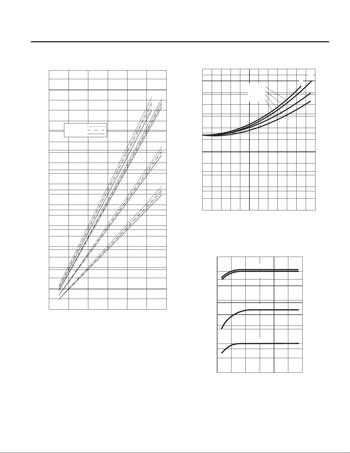
G/H-25 Specifications
Performance Net Positive Suction Head –
NPSHr
Dry Lift
3
GH25 -991-UK00B
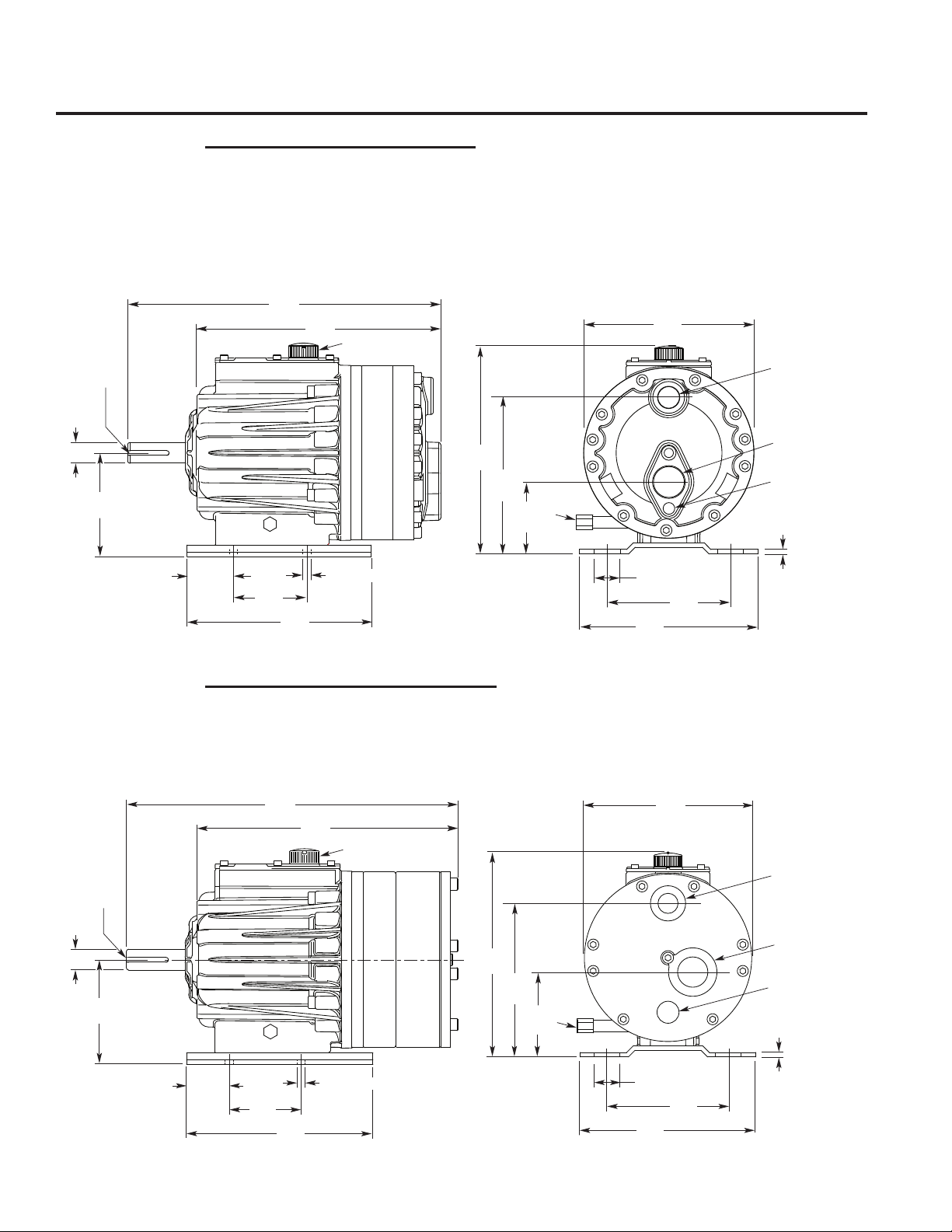
G/H-25 Dimensions
17.01
(432)
13.2
(336)
4.01
(102)
11.58
(294)
1.5
(38)
7.5
(191)
9.98
(253)
0.25
(6.4)
Slot Width
0.42
(11)
Slot Width
4.5
(114)
2.25
(57)
10.0
(254)
5.63
(143)
Ø1.125
(28.55)
9.44
(240)
Oil
Drain
Outlet
H-25: 1" NPT
G-25: 1" BSPT
Inlet
H-25: 1 1/2" NPT
G-25: 1 1/2" BSPT
3/8" - 18 NPT
(Drain Port)
Oil Fill Cap
0.25
(6.4)
Keyway
2.25
(57)
x
W0450
8.71
(221)
17.8
(452)
14.0
(356)
0.42
(11)
Slot Width
4.5
(114)
2.25
(57)
10.0
(254)
5.63
(143)
Ø1.125
(28.55)
Oil Fill Cap
0.25
(6.4)
Keyway
2.25
(57)
x
1.5
(38)
7.5
(191)
9.98
(253)
0.25
(6.4)
Slot Width
Oil
Drain
3/8" - 18 NPT
(Drain Port)
Outlet
H-25: 1" NPT
G-25: 1" BSPT
Inlet
H-25: 1 1/2" NPT
G-25: 1 1/2" BSPT
W0451
4.82
(122)
11.58
(294)
8.71
(221)
9.44
(240)
Models with Metallic Pumping Head
Brass
Cast Iron
316 Stainless Steel
Nickel Alloy (Hastelloy CW12MW)
Models with Non-metallic Pump Head
®
Kynar
Polypropylene
4
GH25 -991-UK00B

GH-25 Installation
Safety Precautions
General remarks
These safety / installation instructions contain fundamental
information and precautionary notes and must be kept available
to all associated with the operation of the pump. Please read
them thoroughly prior to installation, electrical connection and
commissioning of the unit. It is imperative that all other operating
instructions relating to the components of individual units are
followed.
These safety / installation instructions do not take local
regulations into account. The operator must ensure that such
regulations are observed by all, including the personnel carrying
out the installation.
Each pump must be labeled by the end user to warn of any
hazards that the system process may produce; e.g. corrosive
chemicals or hot process etc.
All personnel involved in the operation, maintenance, inspection
and installation of the pump must be fully qualified to carry out
the work. The personnel’s responsibilities, competence and
supervision must be clearly defined by the operator. To the extent
that if the personnel in question is not already in possession of
the requisite know how, appropriate training and instruction must
be provided. In addition, the operator is responsible for ensuring
that the contents of the operating instructions are fully understood
by all the responsible personnel.
When installing a Hydra-Cell pump in conjunction with a motor
or motor and frequency controller the relevant manuals must
be referred to for electromagnetic compatibility. The installation
should conform to EN 61800 and EN 60204.
All safety instructions in this manual and all relevant local health
and safety regulations must be followed.
Attention must be paid to the weight of the pump before
attempting to lift either manually or selecting appropriate lifting
equipment.
5
GH25 -991-UK00B
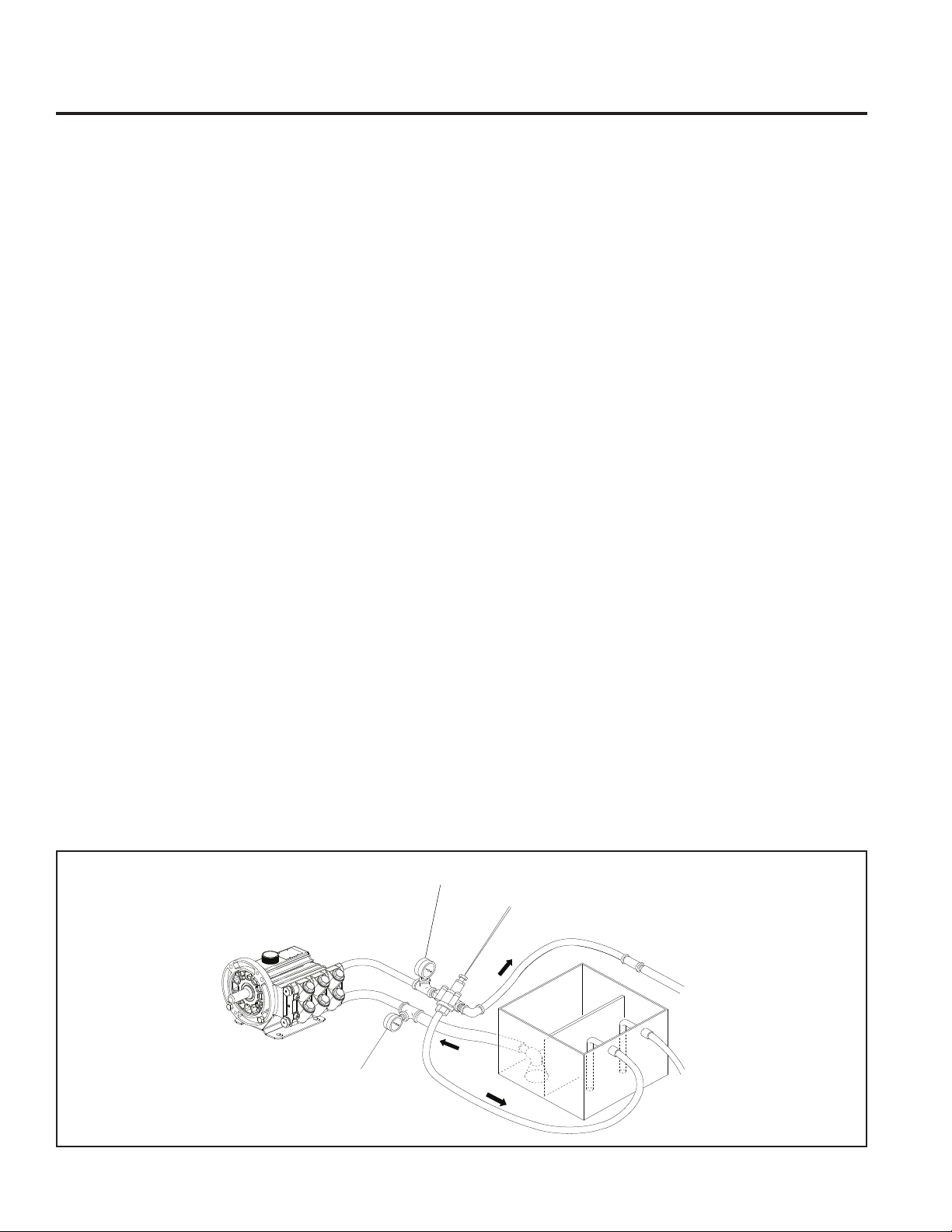
GH-25 Installation
W0520
Suction
Discharge
Line
Inlet
To Tank
Bypass
Line
Line
Pressure
Gauge
Pressure
Regulator
Vacuum Pressure
Gauge
Note: The numbers in parentheses are the reference
numbers on the illustrations in the Parts Manual.
Location
Locate the pump as close to the supply source as possible.
Install it in a lighted clean space where it will be easy to inspect
and maintain. Allow room for checking the oil level, changingthe
oil, and removing the pump head (manifold, valve plate and
related items).
Mounting
The pump shaft can rotate in either direction. To prevent vibration,
mount the pump and motor securely on a level rigid base.
On a belt-drive system, align the sheaves accurately; poor
alignment wastes horsepower and shortens the belt and bearing
life. Make sure the belts are properly tightened, as specified by
the belt manufacturer.
On a direct-drive system, align the shafts accurately. Unless
otherwise specified by the coupling manufacturer, maximum
parallel misalignment should not exceed 0.4 mm (0.015 in.)
and angular misalignment should be held to 1° maximum.
Careful alignment extends life of the coupling, pump, shafts,
and support bearings. Consult coupling manufacturer for exact
alignment tolerances.
Drive couplings, belts and pulleys must be of suitable design,
correctly sized and fitted and rated for the maximum load
required.
On a close-coupled system, coat the motor shaft liberally with
anti-seize.
The pump, motor and related components must be adequately
earthed.
Important Precautions
Adequate Fluid Supply. To avoid cavitation and premature
pump failure, be sure that the pump will have an adequate
fluid supply and that the inlet line will not be obstructed.
See “Inlet Piping”.
Positive Displacement. This is a positive-displacement
pump. To avoid severe system damage if the discharge line
ever becomes blocked, install a relief valve downstream
from the pump. See “Discharge Piping”. A suitable and
calibrated pressure gauge should be installed in the
discharge line close to the pump head.
Safety Guards. Install adequate safety guards over
all pulleys, belts, and couplings. Follow all codes and
regulations regarding installation and operation of the
pumping system.
Shut-Off Valves. Never install shut-off valves between the
pump and discharge pressure regulator, or in the regulator
bypass line.
Freezing Conditions. Protect the pump from freezing. See
also the Maintenance Section.
Working Pump. The pump body will become hot during
operation even if the liquid being pumped is cold.
Consult the Factory for the following situations:
• Extreme temperature applications – above 71°C (160° F)
or below 4.4°C (40° F)
• Pressure feeding of pumps
• Viscous or abrasive fluid applications
• Chemical compatibility problems
• Hot ambient temperatures – above 43°C (110° F)
• Conditions where pump oil may exceed 93°C (200° F)
because of a combination of hot ambient temperatures,
hot fluid temperature, and full horsepower load — an
oil cooler may be required
6
GH25 -991-UK00B

GH-25 Installation
Inlet Piping (Suction Feed)
CAUTION: When pumping at temperatures above 71°C (160° F),
attention must be paid to the vapour pressure curve of the
liquid. A pressure-feed system may be required.
Install drain cocks at any low points of the suction line, to permit
draining in freezing conditions.
Provide for permanent or temporary installation of a vacuum
gauge to monitor the inlet suction. To maintain maximum flow,
vacuum at the pump inlet should not exceed 180 mm Hg at 21°
C (7 in. Hg at 70° F).
Do not supply more than one pump from the same inlet line.
With PTFE diaphragms, the inlet must be flooded.
Supply Tank
Use a supply tank that is large enough to provide time for any
trapped air in the fluid to escape. The tank size should be at least
twice the maximum pump flow rate.
Isolate the pump and motor stand from the supply tank, and
support them separately.
Install a separate inlet line from the supply tank to each pump.
Install the inlet and bypass lines so they empty into the supply
tank below the lowest water level, on the opposite side of the
baffle from the pump suction line.
If a line strainer is used in the system, install it in the inlet line
to the supply tank.
To reduce aeration and turbulence, install a completely
submerged baffle plate to separate the incoming and outgoing
liquids.
Install a vortex breaker in the supply tank, over the outlet port
to the pump.
Place a cover over the supply tank, to prevent foreign objects
from falling into it.
Hose and Routing
Size the suction line at least one size larger than the pump inlet,
and so that the velocity will not exceed 0.3 to 0.9 m/s (1-3 ft/
sec):
For pipe in mm: Velocity (m/sec) = 21.2 x LPM/Pipe ID
For pipe in inches: Velocity (ft/sec) = 0.408 x GPM/Pipe ID2
Keep the suction line as short and direct as possible. A maximum
of 1m (3 feet) is recommended.
Use flexible hose and/or expansion joints to absorb vibration,
expansion, or contraction.
If possible, keep the suction line level. Do not have any high
points to collect vapor unless these high points are vented.
To reduce turbulence and resistance, do not use 90° elbows. If
turns are necessary in the suction line, use 45° elbows or arrange
sweeping curves in the flexible inlet hose.
If a block valve is used, be sure it is fully opened so that the flow
to the pump is not restricted. The opening should be at least the
same diameter as the inlet plumbing ID.
Do not use a line strainer or filter in the suction line unless regular
maintenance is assured. If used, it should have a free-flow area
of at least three times the free-flow area of the inlet.
Install piping supports where necessary to relieve strain on the
inlet line and to minimize vibration.
2
7
GH25 -991-UK00B

GH-25 Installation
Inlet Piping (Pressure Feed)
Provide for permanent or temporary installation of a vacuum/
pressure gauge to monitor the inlet vacuum or pressure.
Pressure at the pump inlet should not exceed 17 bar (250 psi);
if it could get higher, install an inlet pressure reducing regulator.
Do not supply more than one pump from the same inlet line.
Inlet Calculations
Acceleration Head
Calculating the Acceleration Head
Use the following formula to calculate acceleration head losses.
Subtract this figure from the NPSHa, and compare the result to
the NPSHr of the Hydra-Cell pump.
Ha = (L x V x N x C) ÷ (K x G)
where:
Ha = Acceleration head (ft of liquid)
L= Actual length of suction line (ft) — not equivalent length
V= Velocity of liquid in suction line (ft/sec) [V = GPM x (0.408 ÷
N= RPM of crank shaft
C= Constant determined by type of pump — Use 0.066 for D/
K= Constant to compensate for compressibility of the fluid — use:
G= Gravitational constant (32.2 ft/sec
2
pipe ID
G03, M03, M23, G13, D/G10, D/G04 and H/G25 pumps.
Use 0.04 for D/G35 and D/G15 pumps. Use 0.628 for
F/G20/21/22 pumps.
1.4 for de-aerated or hot water; 1.5 for most liquids; 2.5 for
hydrocarbons with high compressibility
)]
2
)
Friction Losses
Calculating Friction Losses in Suction Piping
When following the above recommendations (under “inlet Piping”)
for minimum hose/pipe I.D. and maximum length, frictional losses
in the suction piping are negligible (i.e., Hf = 0) if you are pumping
a water-like fluid.
When pumping more-viscous fluids such as lubricating oils,
sealants, adhesives, syrups, varnishes, etc., frictional losses
in the suction piping may become significant. As Hf increases,
the available NPSH (NPSHa) will decrease, and cavitation will
occur.
In general, frictional losses increase with increasing viscosity,
increasing suction-line length, increasing pump flow rate, and
decreasing suction-line diameter. Changes in suction-line
diameter have the greatest impact on frictional losses: a 25%
increase in suction-line diameter cuts losses by more than
two times, and a 50% increase cuts losses by a factor of five
times.
Consult the factory before pumping viscous fluids.
Minimizing Acceleration Head and Frictional Losses
To minimize the acceleration head and frictional losses:
• Keep inlet lines less than 1 m (3 ft) long
• Use inlet hose at least one size larger than the size of the
inlet port of the pump
• Use soft hose (low-pressure hose, non collapsing) for the
inlet lines
• Minimize fittings (elbows, valves, tees, etc.)
• Use a suction stabilizer on the inlet.
8
GH25 -991-UK00B

GH-25 Installation
Net Positive Suction Head
NPSHa must be equal to or greater than NPSHr. If not, the
pressure in the pump inlet will be lower than the vapor pressure
of the fluid— and cavitation will occur.
Calculating the NPSHa
Use the following formula to calculate the NPSHa:
NPSHa = Pt + Hz - Hf - Ha - Pvp
where:
Pt = Atmospheric pressure
Hz = Vertical distance from surface liquid to pump center line (if
liquid is below pump center line, the Hz is negative)
Hf = Friction losses in suction piping
Ha = Acceleration head at pump suction
Pvp = Ab s olute va por pr e s sure of liq u i d at pumping
temperature
Notes:
• In good practice, NPSHa should be 3 ft greater than
NPSHr
• All values must be expressed in feet of liquid
Atmospheric Pressure at Various Altitudes
Altitude Pressure Altitude Pressure
(ft) (ft of H
0 33.9 1500 32.1
500 33.3 2000 31.5
1000 32.8 5000 28.2
O) (ft) (ft of H2O)
2
Discharge Piping
Note: Consult the Factory before manifolding two or more
pumps together.
Hose and Routing
Use shortest, most-direct route for discharge line.
Select pipe or hose with working pressure rating of at least 1.5
times maximum system pressure. EXAMPLE: Select a 1500-psi
W. P.-rated hose for systems to be operated at 1000-psi-gauge
pressure.
Use about 6 ft (1.8 m) of flexible hose between pump and rigid
piping to absorb vibration, expansion or contraction.
Support pump and piping independently. Size discharge line so
that velocity of fluid will not exceed 2-3 m/sec (7-10 ft/sec):
For pipe in mm: Velocity (m/sec) = 21.2 x LPM/Pipe ID
For pipe in inches: Velocity (ft/sec) = 0.408 x GPM/Pipe ID2
NOTE: Pumps with non-metallic pumping head are limited
to 17 bar (250 psi) maximum working pressure rating.
Pressure Regulation
Install pressure regulator or unloader in discharge line.
Bypass pressure must not exceed pressure limit of pump.
Size regulator so that, when fully open, it will be large enough
to relieve full capacity of pump without over pressurizing the
system.
Locate regulator as close to pump as possible and ahead of
any other valves.
Adjust pressure regulator valve to no more than 10% over
maxi mum working pressure of sys tem. Do not exceed
manufacturer’s pressure rating for pump or regulator.
Route the bypass line to the supply tank, not to the suction line
(to reduce the chance of turbulence and cavitation within the
pump).
If the pump may be run for a long time with the discharge closed
and fluid bypassing, install a thermal protector in the bypass line
(to prevent severe temperature buildup in the bypassed fluid).
The safety, pressure regulating valve must be checked for correct
operation on a regular basis.
2
CAUTION: Never install shutoff valves in the bypass line or
between the pump and pressure regulator or relief valve.
Provide for permanent or temporary installation of pressure
gauge to monitor discharge pressure at pump.
For additional system protection install safety relief valve in
discharge line downstream from pressure regulator.
9
GH25 -991-UK00B
 Loading...