

Page 1
p
panying
Important Safety
Instructions
CAUTION: TO REDUCE THE RISK OF ELECTRIC SHOCK, DO NOT
REMOVE COVER (OR BACK). NO USE-SERVICEABLE PARTS
INSIDE. REFER SERVICING TO QUALIFIED SERVICE PERSONNEL.
POWER SUPPLY:
Connect the supplied adapter to the side of the DVD player in the slot marked “Power
In”. Plug the two-prong end of the power cord to an AC100-240V outlet. If you have
difficulty inserting the plug, turn it over and reinsert it, if the unit will not the used for a
long time, disconnect the plug from the outlet.
NOTE:
Before plugging the power cord into an AC outlet, make sure that all the connections
have been made.
The lightning flash with arrowhead symbol, within an equilateral triangle, is
intended to alert the user to the presence of uninsulated “dangerous
voltage” within the product’s enclosure that may be of sufficient magnitude
to constitute a risk of electric to
The exclamation point within an equilateral triangle is intended to alert the
user to the presence of important operating and maintenance (servicing)
instructions in the literature accom
ersons.
the appliance.
- 1 -
Page 2

CAUTION: These servicing instructions are for use by qualified service personnel only.
To reduce the risk of electric shock, do not perform any servicing other than that
contained in the operating instructions unless you are qualified to do so.
Refer to service manual for servicing instructions.
1) Read these instructions.
2) Keep these instructions.
3) Heed all warnings.
4) Follow all instructions.
5) Do not use near water.
6) Clean only with dry cloth.
Do not block any ventilation openings. Maintain well ventilated conditions around
7)
the product, Do not put product on bed, sofa or anything that blocks ventilation.
Install in accordance with the manufacturer’s instructions.
8) Do not install near any heat sources such as radiators, heat registers, stoves, or
other apparatus (including amplifiers) that produce heat.
9) Do not defeat the safety purpose of the polarized or grounding-type plug. A
polarized plug has two blades with one wider than the other. A grounding type plug
has two blades and a third grounding prong. The wide blade or the third prong is
provided for your safety. If the provided plug does not fit into your outlet, consult an
electrician for replacement of the obsolete outlet.
10) Protect the power cord from being walked on or pinched particularly at plugs,
convenience receptacles, and the point where they exit from the apparatus.
11) Only use attachments/accessories specified by the manufacturer.
12) Use only with the cart, stand, tripod, bracket, or table specified by
the manufacturer, or sold with the apparatus. When a cart is used,
use caution when moving the cart/apparatus combination to avoid
injury from tip-over.
13) Unplug this apparatus during lightning storms or when unused for long periods of
time.
14) Refer all servicing to qualified service personnel. Servicing is required when the
apparatus has been damaged in any way, such as power-supply cord or plug is
damaged, liquid has been spilled or objects have fallen into the apparatus, the
apparatus has been exposed to rain or moisture, does not operate normally, or has
been dropped.
15) Apparatus shall not be exposed to dripping or splashing and no o bjects filled with
liquids, such as vases, shall be placed on the apparatus.
Note: Do not touch the color TFT LCD screen by hand directly.
Important Safety
Instructions
- 2 -
Page 3

Important Safety
Instructions
Changes or modifications not expressly approved by the party responsible for
compliance could void the user's authority to operate the equipment.
This product has been tested and complies with the specifications for a Class B digital
device, pursuant to Part 15 of the FCC Rules. These limits are designed to provide
reasonable protection against harmful interference in a residential installation. This
equipment generates, uses, and can radiate radio frequency energy and, if not
installed and used according to the instructions, may cause harmful interference to
radio communications. However, there is no guarantee that interference will not occur
in a particular installation. If this equipment does cause harmful interference to radio or
television reception, which is found by turning the equipment off and on, the user is
encouraged to try to correct the interference by one or more of the
following measures:
Reorient or relocate the receiving antenna
Increase the separation between the equipment or devices
Connect the equipment to an outlet other than the receiver's
Consult a dealer or an experienced radio/TV tech nician for assistance
Operations are subject to the following two conditions:
1. This device may not cause harmful interference, and
2. This device must accept any interference received, including
interference that may cause undesired operation
FCC Radiation Exposure Statement
The antennas used for this transmitter must be installed to provide a
separation distance of at least 20 cm from all persons and must not be collocated or
operating in conjunction with any other antenna or transmitter.
- 3 -
Page 4

Important Safety
Instructions
Copyright Protection
This product incorporates copyright protection technology that is protected by U.S.
patents and other intellectual property rights. Use of this copyright protection
technology must be authorized by Macrovision, and is intended for home and other
limited viewing uses only unless otherwise authorized by Macrovision. Reverse
engineering or disassembly is prohibited.
- 4 -
Page 5

This product is designed portability and handily, with a stylish appearance, and its
base station is a wireless transmitter. It incorporates wireless TV/AV receiver. It is
conveniently for using and taking.
Features
Multiple Mode
AV m ode
Wireless A V (WiFi AV) mode.
In wireless AV input status:
W-AV1 mode
W-AV2 mode
W-SV (S-VIDEO) mode
TV mode
High Quality Features
Wireless Channel Feature
Adopt multi wireless channel in oder to avoid interruption.
Bitrate Feature
Adopt image compression bitrate to adjust image quality and transmission distance.
Auto Searching and Connecting Function
The receiver of the unit can automatically search and connect the signal from transmitter
of the unit.
High Resolution
Adopt an MPEG2 decoding format to achieve horizontal resolution more than 500 lines.
LCD (Liquid Crystal Display)
Designed with 10.2 inch color TFT LCD clearly shows the data.
Stereo amplifier
Built-in 2x1.5w speakers output high quality sound.
NOTE: It is normal for a TFT screen to experience some light or dark spots appearing on
the LCD screen.
- 5 -
Page 6
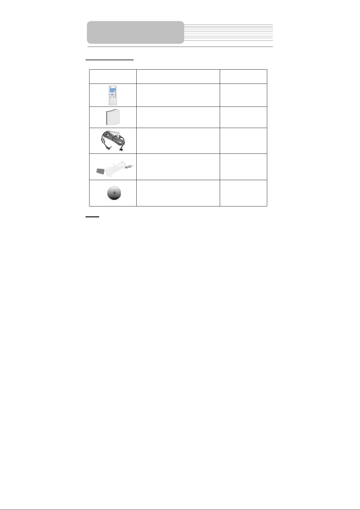
Accessories
Accessories List
ITEM
NAME
Remote Control Unit
QTY
1
NOTE
Accessories and their parts numbers are subject to modification without prior notice due
to improvements.
Owner’s Manual
Power Adapter
IR Blaster cord
Cell for Remote Control
1
1
1
1
6
Page 7

Important Safety Instructions
Features
Accessories
View of the Unit
Base System Connection
Player System Connection
Remote Control
Using the Wireless System
Troubleshooting
Warning
Specifications
Contents
…………………………………………….1
………………………………………….….4
………………………………………….….5
………………………………………..…...7
…………………………………….…...…10
…………………………………………....12
…………………………………………....14
…………………………………………....16
…………………………………..………..20
………………………………………..…..21
…………………………………………….22
7
Page 8

View of the Unit
Front View
1. button
Power/standby button.
2. MODE button
Adjust the brightness, contrast and color realized by pressing VOL/ VOLbutton
on the front pane to make adjustment.
3. VOL/button
Adjust the speaker volume, or modulate the panel mode (brightness, contrast and
color).
4. MENU button
Enter wireless function menu.
5. INPUT/ENT button
Shows the transmitter source selection among W-AV1, W-AV2, W-SV, TV. Or
confirm the adjustment of wireless function menu selection.
6. CH/ button
Select TV channels or adjust related wireless function combined with SOURCE/ENT
button.
8
Page 9

View of the Unit
7.Rechargeable battery pack
8. Headphone Jack
Connect to the Headphone.
9. VIDEO input/output Jack
Press WIFI/AV button on the remote control to switch to input status, it is VIDEO
input Jack, while switch to output status, it is VIDEO output Jack.
10. AUDIO input/output Jack
Press WIFI/AV button on the remote control to switch to input status, it is AUDIO
input Jack, while switch to output status, it is AUDIO output Jack.
11. TFT LCD
10.2” color TFT LCD panel.
12. Speakers
13. Infrared receiver
Receives the signal from the remote control.
14. Charging Contacts
Charges the Rechargeable battery pack of this unit.
15. Battery charging indicator
Light turns red when the battery is in charging; Light turns blue when the battery is
fully charged.
16. Power supply indicator
When the power switch button is pushed to on, the light turns yellow.
When the unit is in the standby status, the light turns green.
When the unit is in the working status, the light turns red.
17. POWER Switch
Turn power on or off.
Notes: Introduction of Wirelss system working parts refers to Page 16—Page 19.
9
Page 10

View of the Unit
BASE View
1. Charging Contact Part
Charges the Rechargeable battery pack of this unit.
2. POWER Switch
Turn base of this unit power on or off.
3. Power supply indicator
When power is on, the light is green.
4. DC 9.5V IN Jack
5. IR BLASTER
IR BLASTER cord jack.
6. S-Video input Jack
7 . OUT
CATV signal output jack.
8. IN
CATV signal input jack.
9. AV IN
L/R audio and video input jack.
10
Page 11

This base part of this unit can recicieve multi-AV/TV signals.
Connecting to the Power Adapter
Power is supplied through the provided appropriate power adapter, one end is connected
to the DC 9.5 V IN jack on the rear panel of the unit, the other end to the AC100~240V
wall outlet.
Base System Connection
Connecting to External AV Source/S-video Signal source
Connect the transmitter to external signal source as the picture below.
11
Page 12

Base System Connection
Connecting to TV Signal source
Connect the transmitter to an external signal source: TV. When the TV signal is set to
input to this unit, It also can be output to a TV.
Connecting to IR Blaster Cord
Connecting to IR Blaster Cord as shown below. Put the infrared transmittering terminal in
the front of the remote control sensor of the other device. Through the IR Blaster Cord,
you can control external input signal source through operation of receiving terminal.
12
Page 13

Do not connect the power cord until all other connections have been made.Keep it away
from the water source.
Connecting to External AV Source
The unit supports AV signal input function from another source. Please use the
audio/video cable(included) to connect the unit to the external AV signal source such as
a DVD, VCR etc. Press the WIFI/AV button on the remote control to enter AV input
status.
Player System
Connection
Connecting to TV
The unit supports AV signal output function to another device. Connect as shown below,
13
Page 14

Player System
Connection
Connecting to Headphone
Connect the headphone to the headphone jack on the unit.
When headphone is connected, the speakers will automatically turn off. Please adjust
the volume before using headphones as this may cause hearing loss if they are too
lound.
14
Page 15

Remote Control
Remote Control Drawing
1. [POWER]
Power/standby button.
2. [0-9]
Under TV mode, press to select TV channel.
3. [-/--/+100 ]
Under TV mode, press this button to show
channels above 100.
4. [CH+/ CH- ]
Press to select TV channels forward or
backward.
5.[VOL+/VOL- ]
Adjust the speaker volume, or change the
panel mode (brightness, contrast and color).
6. [OK]
Press to confirm function selection.
7. [DISP]
In the TV mode, Press to display the wireless
channel number.
8. [MUTE]
Turn the speaker output on/of f .
9.[LAST]
Return to the TV channel last viewed.
10. [INPUT]
Displays the transmitter source: W-AV1,
W-AV2, W-SV, TV.
11. [WIFI/AV]
Switches between input and output status of
the reciever of the unit.
12. [MODE]
Adjust the brightness, contrast and color
using the VOL/ VOLbuttons on the front
panel.
13. [WIFI MENU]
Press to enter wireless function setup.
15
Page 16

g
Remote Control
Preparation of Remote Control
Insert the batteries while observing
+
-
1. Refering to the drawing, take out
the empty battery receptacle.
2. A separating film was applied to
the battery for shipment.
Remove this film.
3. Insert the battery into the
receptacle and insert it into the
remote.
4. Under normal usage the battery
will last for six months.
5. Take out battery when the
remote is not in use for a long
time.
Using of Remote control
Point the remote control unit from no
more than about 5m from the remote
control sensor and within about 60
rees of the front of the unit.
de
The operating distance may vary
depending to the surrounding
brightness.
Notes:
Do not point bright lights directly at
the remote control sensor.
Do not place objects between the
remote control unit and the remote
control sensor.
Do not use this remote control unit
while simultaneously operating the
remote control unit of any other
16
equipment.
Page 17

Connect CATV or AV signal source to the base station of the unit correctly.
Connect the reciever of the unit correctly.
Push power Switch button the transmitter of the unit to on. Power supply indicator of
the transmitter of the unit turns green.
Push power Switch button of the reciever of the unit to on.
yellow, after a while, the reciever of the unit enter the standby status, the light turns
Press the power button of the reciever of the unit to the reciever of the unit and it
green.
enter the working status, the light turns red. At this time, the unit will connect
automatically.
The following screens instances will appear when these phenomenon occur:
1. The screen will display the following when the transmitter is not connected.
Press ENT to rescan the transmitter.
2. The screen will display the following when the transmitter is connected.
After a while, the unit is successfully connected.
CONNECTING……
Transmitter not found
ENT to rescan transmitter
CONNECTING……
Using the Wireless
System
Power supply indicator lights
- 17 -
Page 18

Using the Wireless
System
The base station of the unit possesses multi-audio and video input jack (TV, W-AV1,
W-AV2, W-SV), and it can be connected to an external signal source.
signal source can be accomplished by using the panel button on the unit or remote
control .
Changing the
Switching Audio and Video Signal
• Panel button mode:
Press the “INPUT/ENT ” button to switch among TV, W-AV1, W-AV2, W-SV
• Remote control mode:
Press the "INPUT" button to switch among TV, W-AV1, W-AV2, W-SV.
Switching Wireless channel
You can switch the wireless channel easily.
• Panel button mode:
Under the AV or TV status, press the Menu button, The screen will display
[WIRELESS CHANNEL XXX] , press the CH/ button to search a wireless
channel forward or backward, The screen will display [WIRELESS CHANNEL
YYY], press the INPUT/ENT button to confirm,The Wireless channel is changed.
• Remote control mode:
Under the AV or TV status, press the WIFI MENU button, The screen will display
[WIRELESS CHANNEL XXX] item, then press the CH+, or CH- button to search
a wireless channel forward or backward, The screen will display [WIRELESS
CHANNEL YYY] item, press the ENT button to confirm. The Wireless channel is
changed. (XXX-----current wireless channel, YYY------ changed wireless
channel).
Notes: When wireless channel is switched to [WIRELESS CHANNEL AUTO] item,
press the INPUT/ENT button on the panel or ENT button on the remote control to scan
a clean wireless channel automatically. When abnormal signal phenomenon appearing,
user can avoid the signal interruption through switching the wireless channel.
- 18 -
Page 19

Using the Wireless
System
TUNER AUTO SCAN Operation
During first operation or when the TV is moved to another area,you need to realized the
tuner's auto scanning. It will take several minutes to complete scanning. After the
scanning, the TV channel will be located in the first TV channel which has TV signal,
displaying the program and channel number.
• Panel button mode:
Under the TV status, press the Menu button continuously,The screen will display
[TUNER AUTO SCAN OFF], press the CH/ button to select [TUNER AUTO
SCAN NTSC AIR] or [TUNER AUTO SCAN NTSC HRC] or [TUNER AUTO
SCAN NTSC IRC] or [TUNER AUTO SCAN NTSC STD], press the INPUT/ENT
button to start the automatic tuner scanning.
• Remote control mode:
Under the TV status, press the WIFI menu button, The screen will display
[TUNER AUTO SCAN OFF] item, then press the CH+, or CH- button to select
[TUNER AUTO SCAN NTSC AIR], [TUNER AUTO SCAN NTSC HRC],
[TUNER AUTO SCAN NTSC IRC], [TUNER AUTO SCAN NTSC STD] item,
press the ENT button to start the automatic channel scanning.
BITRATE Operation
Bitrate setup is helpful for image quality and transmission distance. High bitrate: image
is more clear suitable for near distance viewing. Low bitrate: the wireless transmission
distance is further, suitable for far distance viewing. Please set the bitrate to low, If the
quality of image transmision is bad.
• Panel button mode:
Under TV status, press the Menu button continuously,The screen will display
[MPEG BITRATE HIGH ] item, then press the CH/ button, the screen will
display [MPEG BITRATE HIGH], [BITRATE MID], [MPEG BITRATE LOW]. Press
the INPUT/ENT button to confirm.
• Remote control mode:
Under TV status, press the WIFI menu button, The screen will display [MPEG
BITRATE HIGH] item, then press the CH+ or CH- button, the screen will display
[MPEG BITRATE HIGH], [BITRATE MID], [MPEG BITRATE LOW]. Press ENT
button to confirm.
- 19 -
Page 20

Using the Wireless
System
Selecting the Language
You can select language through the operation:
• Panel button mode:
Under TV status, press the Menu button continuously,The screen will display
[OPERATE LANGUAGE English] item, then press the CH/ button to select
[OPERATE LANGUAGE French], [OPERATE LANGUAGE Spanish] item, press
the INPUT/ENT button to start the transmitter scanning.
• Remote control mode:
Under TV status, press the WIFI menu button continuously, The screen will
display [OPERATE LANGUAGE English] item, then press the CH+, or CHbutton to select [OPERATE LANGUAGE French], [OPERATE LANGUAGE
Spanish] item, press the ENT button to start the transmitter scanning.
Scanning for the transmitter signal
You can rescan the transmitter through the following operation:
• Panel button mode:
Under TV status, press the Menu button continuously,The screen will display
[SCAN TRANSMITTER OFF], press the CH/ button to select [SCAN
TRANSMITTER ON], press the INPUT/ENT button to start the transmitter
scanning.
• Remote control mode:
Under TV status, press the WIFI menu button continuously, The screen will
display [SCAN TRANSMITTER OFF] item, then press the CH+, or CH- button
to select [SCAN TRANSMITTER ON] item, press the ENT button to start the
transmitter scanning.
Notes: The operation will takes take some time. the screen display “System
Initiation…”, after several seconds, the system accomplishs the auto scanning. The
unit will find all transmitter signals within range. The user may change the connection.
Display Screen Setup
• Panel button mode:
Under AV or TV status, press the MODE button continuously to select brightness,
contrast, hue. then press the VOLor VOL button to adjust brightness,
contrast, hue.
• Remote control mode:
Under AV or TV status, press the MODE button continuously to select brightness,
contrast, hue. then press the VOL+ or VOL- button to adjust brightness, contrast,
hue.
Output/Input Switching Operation
• Remote control mode:
Press the WIFI/AV button on the remote control to enter the AV input or AV
output status.
- 20 -
Page 21

Symptom What To Check
LCD has not displaying a
picture.
There is no image, or there
is mosaic iamge, unstable
image .
Louderspeaker has no
sound.
The remote control does not
work.
The reciever of the unit do es
not work in wireless mode.
The connection time in the
wireless status is beyond
one minute.
Troubleshooting
• Make sure the power has been switched on.the unit
is connected correctly, to the power adapter. Check
the transmitter input signal.
• check the external audio and video signal source
has been connected, and the input source is
correct, and receiving a signal withing range.
• check whether the volume is adjusted to the
minimum level, whether the he adphone jack has
been connected to the headphone, whether the
reciever of the unit is in the pause status.
• Make sure there aren’t any obstructions between
the remote control and the reciever of the unit.
• Make sure you are pointing t he r emote cont rol at t he
remote control sensor of the reciever of the unit.
• Make sure batteries are inserted correctly (check
polarity).
• Replace weak batteries.
• Make sure that the transmitter has been
connected correctly. .
• Make sure that the power switch of transmitter
has been pushed to on.
• Make sure that the distance between transmitter
and the receiver is within 20 meters.
• Turn the power of reviever off.
• Make sure the transmitter is connected correctly.
• Push the power switch of the reciever to on.
- 21 -
Page 22

Warning
It is normal that the temperature of the unit rises during operation.
Unit picture display will lasts for approx 15 seconds after the unit enters the working
status.
Power consumption of the unit is massive. Under no operation, please turn the power off.
The unit adopt 802.11a wireless transmission standards. The majority of the electric
wave transmission is wireless electric wave of direct transmission. So It is reflected when
electric wave encounters wall, furniture, or building. It produces multi-direction reflecting
wave. The instances will influence normal operation of the unit. So we need to try to
avoid these enviroment influence.
1. With in building constructed by ferroconcrete.
2. There are crowds, building or barrier nearby.
3 . Interruption of massive power consumption unit such as wireless electric wave,
micro-wave oven.
Try to put the transmitter to the high position in order to get the best the transmission and
receiving effect . when the interruptions above exit, please adjust the distance between
transmitter and reiciever, and bitrate setup to achieve the lest receiving effect.
- 22 -
Page 23

Specifications
/
TFT-LCD screen size 10.2 inches
TV Type NTSC
Wireless Standards IEEE802.11a
Wireless Channel Number 6
Communication Range
Modulation
UHF Low Frequency
UHF High Frequency
UHF Frequency
Power AC100~240V(50/60Hz)
Transmitter Power Consumption 12W
Recievrer Power Consumption 16W
Transmitter Dimensions 233mm x128mm x143mm
Indoors: Approx 20m (Relying on environment )
OFDM
55.25Hz~151.25 Hz
157.25Hz~451.25 Hz
457.25Hz~799.25 Hz
Reviever Dimensions 320mm x196mm x51mm
Unit Weight approx 2.9kg
DESIGN AND SPECIFICATIONS ARE SUBJECT TO CHANGE WITHOUT NOTICE
- 23 -
 Loading...