

Page 1
Page 2

Page 3
I
I
•
© WANG
LABORATORIES,
INC., 1970
Tewksbury, Mass.
01876
Telephone (617)
851-7all
TWX
110
343-6769
REFEREN~E
M:ANUAL
,
,
t,
Page 4
FOREWORD
This reference manual is designed to provide the user with
a basic understanding and practical guidance
in
the
use
of
Wang's 700A/B Electronic Calculators.
The
aim has been to assist
the
user
by
presenting
the
most
useful technique, concept and
method
for utilizing
the
700
to
its best advantage.
For
further information,
contact
your
local sales office or
Wang Laboratories, Inc., 836
North
Street, Tewksbury,
Massachusetts 01876.
Page 5

SECTION
I -
INTRODUCTION
SECTIONII-
EXPLANATIONOFKEYS
SECTION
III -
PROGRAMMING
SECTIONIV-
PROGRAM
CONCEPTS
SECTIONV-DECISION
COMMANDS
SECTIONVI-
PROGRAMMING
TECHNIUUES
USINGATAPE
CASSETTE
SECTION
VII-ADDITIONAL
COMMANDS
NOT
FOUNDONTHE
700
KEYBOARD
SECTION
VIII-TRIGONOMETRIC
PACKAGE
PROGRAM,
STATISTICAL
PACKAGE
PROGRAM
SECTIONIX-
SAMPLE
PROGRAMS
SECTIONX-WARRANTY,
SERVICE
AND
MAINTENANCE
Page 6

Page 7
TableofContents
TABLE
OF
CONTENTS
SECTION
I -
INTRODUCTION
Introduction
. . . . . .
• • • • • • • • • • • • • • • • • • • •
1-1
• • • •
SECTIONII-
EXPLANATION
OF
KEYS
ModesofOperation.
. . . . . . . . . . . . . . . . . . . . . . .
Run Mode . . . . . . . . . . . . . . . . . . . . . . . . .
..
.
Learn
Mode'.
. . . . . . . . . . . . . . . . . . . . . . . . .
.'
Learn-Print
Mode.
. . . . . . . . . . . . . . . . . . . . . . . .
List-Program
Mode
. . . . . . . . . . . . . . . . . . . . . . . .
Turning
the
700
ON.
. . . . . . . . . . . . . . . . . . . . . .
Non-Programmable
Key
. . . . . . . . . . . . . . . . . . . . . .
Prim
e . . . . . . . . . . . . . . . . . . . . . . . . . . . . .
Program
Counter
and
Set
PC . . . . . . . . . . . . . . . . . . . .
S
te
p.
. . . . . . . . . . . . . . . . . . . . .
..
. . . . . . .
Verify
Program
. . . . . . . . . . . . . . . . . . . . . . . . .
Record
Program
. . . . . . . . . . . . . . . . . . . . . . . . .
The
Display.
. . . . . . . . . . . . . . . . . . . . . . . . . .
X-
Register
. . . . . . . . . . . . . . . . . . . . . . . . . . .
En
tering
aNum
ber
. . . . . . . . . . . . . . . . . . . . . . . .
Set
Exp
. . . . . . . . . . . . . . . . . . . . . . . . . .
..
.
Y-Register . . . . . . . . . . . . . . . . . . . . . . . . .
..
.
Program-Error
Indicator
. . . . . . . . . . . . . . . . . . . . . .
Data
Storage
Registers.
. . . . . . . . . . . . . . . . . . . . . .
Direct
Addressing
. . . . . . . . . . . . . . . . . . . . . . . .
Toggle
Switches
and
Special
Function
Keys
. . . . . . . . . . . . . .
S
tore
Direct.
. . . . . . . . . . . . . . . . . . . . . . . . . .
Recall
Direct
. . . . . . . . . . . . . . . . . . . . . . . . . .
Exchange
Direct
. . . . . . . . . . . . . . . . . . . . . . . . .
Add,
Subtract,
Multiply,
and
Divide
Direct.
. . . . . . . . . . . . . .
Indirect
Addressing.
. . . . . . . . . . . . . . .. . . . . . . . .
Indirect
Keys
. . . . . . . . . . . . . . . . . . . . . . . . . .
AdvantagesofIndirect
Addressing
. . . . . . . . . . . . . . . . . .
Recall
Residue.
. . . . . . . . . . . . . . . . . . . . . . . . .
Addition,
Subtraction,
Multiplication.
. . . . . . . . . . . . . . . .
Division . . . . . . . . . . . . . . . . . . . . . . . . . .
..
.
Write
Commands.
. . . . . . . . . . . . . . . . . . . . . . . .
Group
I -
Group
2.
. . . . . . . . . . . . . . . . . . . . . . .
SECTION
III -
PROGRAMMING
Coding.
. . . . . . . . . . . . . . . . . . . . . . . . . . . .
GeneratingaCode
Using
Special
Function
Keys
and
Toggle
Switches
Core
Memory
. . . . . . . . . . . . . . . . . . . . . . . . . .
NumberofRegisters
Occupied
By a
Program
. . . . . . . . . . . . . .
SECTIONIV-
PROGRAM
CONCEPTS
Programming
Concepts
. . . . . . . . . . . . . . . . . . . . . .
Mark
and
Search
Commands
. . . . . . . . . . . . . . . . . . . .
Su
brou
tine
. . . . . . . . . . . . . . . . . . . . . . . . . . .
Double-Level
Subroutines
(oraSubroutine
withinaSubroutine)
. . . . . .
v
2-1
2-1
2-1
2-1
2-2
2-2
2-2
2-2
2-3
2-3
2-4
2-4
2-4
2-5
2-5
2-5
2-6
2-8
2-9
2-9
2-9
2-12
2-12
2-13
2-13
2-14
2-14
2-16
2-16
2-17
2-18
2-20
2-21
3-1
3-2
3-3
3-5
4-1
4-2
4-5
4-7
Page 8
TableofContents
TABLE
OF
CONTENTS (Continued)
SECTION
V - DECISION
COMMANDS
DECISIONS.
. . . . . . . . . . . . . . . . . . . . . . . . . .
5-1
S
kipifY = X . . . . . . . . . . . . . . . . . . . . . . . . 5-1
Skip
if
Y > X . . . . . . . . . . . . . . . . . . . . . . . .
5-
2
SkipifY<X
5-3
Skip
if
Error
. . . . . . . . . . . . . . . . . . . . . . . . 5-3
PROGRAMMING
TECHNIQUES
. . . . . . . . . . . . . . . . . . 5-4
Looping
Using a
Counter.
. . . . . . . . . . . . . . . . . . . 5-4
Looping
WithoutaCounter.
. . . . . . . . . . . . . . . . . . 5-6
Scanning a
Table.
. . . . . . . . . . . . . . . . . . . . . . 5-8
Go
.. ..... .. .. ..... .. ..
. . . . . . .
.. .....
. .
..
. . . 5-9
SECTIONVI-
PROGRAMMING
TECHNIQUES USING A TAPE CASSETTE
Tape
Cassette . . . . . . . . . . . . . . . . . . . . . . . . . .
6-1
Tape
Drive
Operation
. . . . . . . . . . . . . . . . . . . . . . . 6-2
Machine-Error
Indicator
. . . . . . . . . . . . . . . . . . . . . . 6-2
ProtectionofProgramonTape
. . . . . . . . . . . . . . . . . . . 6-3
What
is
a Program Block? . . . . . . . . . . . . . . . . . . . . . 6-3
End
Program
. . . . . . . . . . . . . . . . . . . . . . . . . . 6-4
HowtoLearn
a Program
Into
Core
From
the
Keyboard.
. . . . . . . . . 6-5
HowtoTransfer
a Program
From
CoretoTape
. . . . . . . . . .
.,
6-6
HowtoLoad
a Program
From
Tape
into
Core.
. . . . . . . . . . . . . 6-7
Bypassing
Program
Blocks . . .
...
. . . . . . . . . . . . . . . . 6-8
Procedure
for
Correcting
Single
Program
Step.
. . . . . . . . . . . . . 6-8
Procedure
for
InsertingExtra
Program
Steps
. . . . . . . . . . . . . . 6-9
Programming
Techniques
Using
Tape
Cassette.
. . . . . . . . . . . . . 6-9
Creating a Multi-Block
Tape
. . . . . . . . . . . . . . . . . . . . 6-11
SECTION
VII
- ADDITIONAL
COMMANDS
NOT
FOUND
ON
THE
700
KEYBOARD
Pause
Command
. . . . . . . . . . . . . . . . . . . . . . . . .
7-1
Write
Alpha
Pause . . . . . . . . . . . . . . . . . .
..
. . . .
7-1
Storage
Commands
(Direct
Accesstoand
from
the
V-Register) . . . . . . . 7-2
Decisions.
. . . . . .
.'.
. . . . . . . . . . . . . . . . . . . 7-2
X-Register . . . . . . . . . . . . . . . . . . . . . . . . . 7-3
V-Register . . . . . . . . . . . . . . . . . . . . . . . . . 7-3
Shifting
Commands.
. . . . . . . . . . . . . . . . . . . . . . . 7-4
SECTION
VIII
- TRIGONOMETRIC
PACKAGE
PROGRAM
STATISTICAL PACKAGE
PROGRAM
Trig
Pack.
. . . . . . . . . . . . . . . . . . . . . . . . . . .
8-1
Speed
and
Accuracy
. . . . . . . . . . . . . . . . . . . . . . . 8-2
To
Load
the
Trig
Package . . . . . . . . . . . . . . . . . . . . . 8-2
Using
the
Trig Package . . . . . . . . . . . . . . . . . . . . . . 8-3
Program Use . . . . . . . . . . . . . . . . . . . . . . . . . . 8-4
Designofthe
Trig
Pack
. . . . . . . . . . . . . . . . . . . . . . 8-4
Statistical Package . . . . . . . . . . . . . . . . . . . . . . . .
8-
5
Assignment
of
Special
Operations
Key
for
a User's
Own
Subroutines.
. . . .
8-6
•
VI
Page 9
!'.-
",
1
,_-
C
o
to,
,
,
t.
t:->·
~:<:
o
TableofContents
TABLE
OF
CONTENTS (Continued)
SECTION
IX
- SAMPLE PROGRAMS
Algebra
of
Complex Numbers (Program) .
• •
• • • • •
•
• • •
•
•
•
•
9-1
SECTION X - WARRANTY, SERVICE AND MAINTENANCE
Warranty.
• •
• • •
• • •
• • • •
• •
• • •
•
•
•
• • • • • •
•
10-1
Post-Warranty Service Availability
•
•
• • •
•
•
•
•
•
•
• • • •
•
•
•
10-1
Annual Maintenance
Contract.
• • •
• • •
•
• •
•
• •
• • • • • •
•
.10-1
Post-Warranty Service Call Without Maintenance
Contract
• •
• • • • •
•
•
10-1
In-House Maintenance Capability
• •
• • •
•
• • • •
•
•
•
•
•
• •
•
10-2
APPENDIX
Typing Conventions
• • • •
•
•
•
•
• •
• •
•
•
• •
•
• • • • •
•
A-I
Index
•
• •
•
• • • •
•
•
•
•
•
•
• •
•
• • •
•
•
• • • • • •
•
A-4
..
Vll
Page 10
RUN
LEARN
LEARN
LIST
PRINT
PROGRAM
i ,
I
RELEASEIIFORWARDIITAPE
Rl!ADYIIREWIND
I
o 0
PROGRAM
MACHINE
ERROR
ERROR
,
0000
BC4020
10
00
01
02 03 04 05 06 07
06 09
10
11
12
13
14
15
0
DEGREE
RADIANS
SINX
COSX
TANX
SIN-1 COS-I
TAN-
1
TO
POLARTORECT
SINHX
COSHX
TANHX
SINH-
1
COSti~
TANW'
0
TO
RADIANS
TO DEGREES
X
X X X
X
,.
....
,.
...
SKIP
WRITE
END
RECALL
~
,.
.....
,.
RECALL
CHANGE
{X
CLEAR
LOAD
ALPHA
ALPHA
INDIR
DIRECT
SIGN
X'
X
PROG
IF
MARK
PRIME
INDIR
DIRECT
ERROR
...
•
SKIP
STORE
• •
STORE
END
VERIFY
•
7
B 9
RETURN
WRITE
l/X
INDIR
INDIR
DIRECT
DIRECT
-
PROG
IF
•
PROG
Y~X
INTEGER
RECALL
X
X
l
SKIP
Ixi
RESIDUE
INDIR
DIRECT
X
4 5
6
STOP
IF
GROUP
SET
X
Y=X
1
PC
-+
-
-
SKIP
lOx
LOG,.X
1T
INDIR
DIRECT
-
1
2
3
IF
GROUP
RECORD
Y<X
2
PROG
GO
eX
0
+
+
0
SET
SEARCH
STEP
LOG.X
INDIR
DIRECT
+ •
EXP
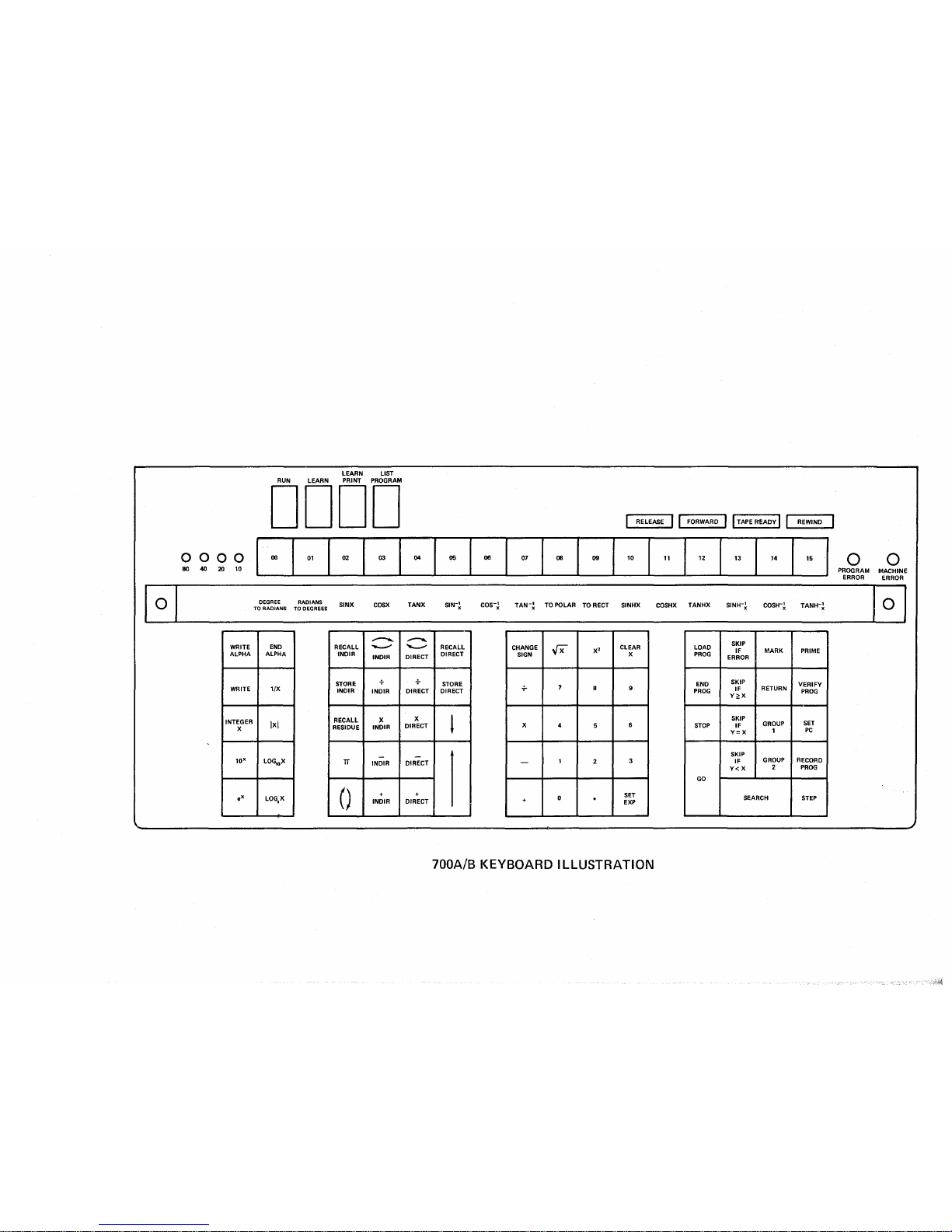
700A/B KEYBOARD
ILLUSTRATION
Page 11
Section I
Introduction
SECTION I
INTRODUCTION
•
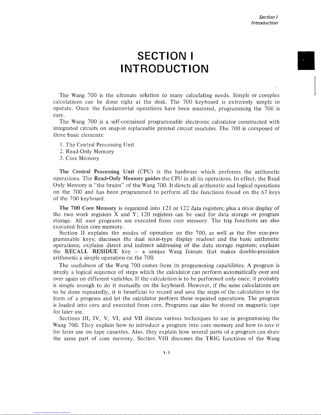
The
Wang 700isthe
ultimate solution
to
many calculating needs. Simpleorcomplex
calculations can be
done
right
at
the desk. The
700
keyboard is extremely simple to
operate. Once
the
fundamental
operations have been mastered, programming the 700
is
easy.
The
Wang 700isa self-contained programmable electronic calculator
constructed
with
integrated circuits on snap-in replaceable printed circuit modules.
The
700iscomposed
of
three basic elements:
1.
The
Central Processing Unit
2.
Read-Only Memory
3.
Core Memory
The
Central Processing
Unit
(CPU)
is
the
hardware which performs the arithmetic
operations.
The
Read-Only Memory guides
the
CPU in all its operations. In effect,
the
Read
Only Memory is
"the
brains"ofthe Wang 700.Itdirects all arithmetic and logical operations
on
the
700 and has been programmedtoperform all
the
functions found
on
the
67 keys
of
the
700
keyboard.
The
700
Core Memory is organized into 121or122
data
registers; plus a nixie display
of
the two work registers X and
Y;
120 registers can be used for
data
storage
or
program
storage. All user programs are executed from core memory.
The
trig functions are also
executed from core memory.
Section II explains
the
modes
of
operation on
the
700,aswell
as
the
five non-pro-
grammable keys; discusses
the
dual nixie-type display
readout
and
the
basic arithmetic
operations; explains direct and indirect addressing
of
the
data
storage registers; explains
the RECALL RESIDUE key
_.
a unique Wang feature
that
makes double-precision
arithmetic a simple
operationonthe 700.
The usefulness
of
the
Wang
700
comes from its programming capabilities. A program
is
simply a logical sequenceofsteps which
the
calculator can perform automatically over and
over again
on
different variables.Ifthe
calculationisto
be performed only once, it probably
is
simple enoughtodoitmanually
on
the keyboard. However,ifthe
same calculations are
tobedone
repeatedly, itisbeneficialtorecord and save
the
stepsofthe calculation in the
form
of
a program
and
let
the
calculator perform these repeated operations.
The
program
is
loaded into core and executed from core. Programs can also be stored
on
magnetic tape
for later use.
Sections III, IV,
V,
VI, and VII discuss various techniquestouse in programming the
Wang
700.
They
explain
how
to introduce a program into core memory and howtosave it
for later use
on
tape cassettes. Also,
they
explain how several partsofa program can share
the same
part
of
core memory. Section VIII discusses
the
TRIG
functions
of
the
Wang
1 - 1
Page 12
Section I
Introduction
INTRODUCTION
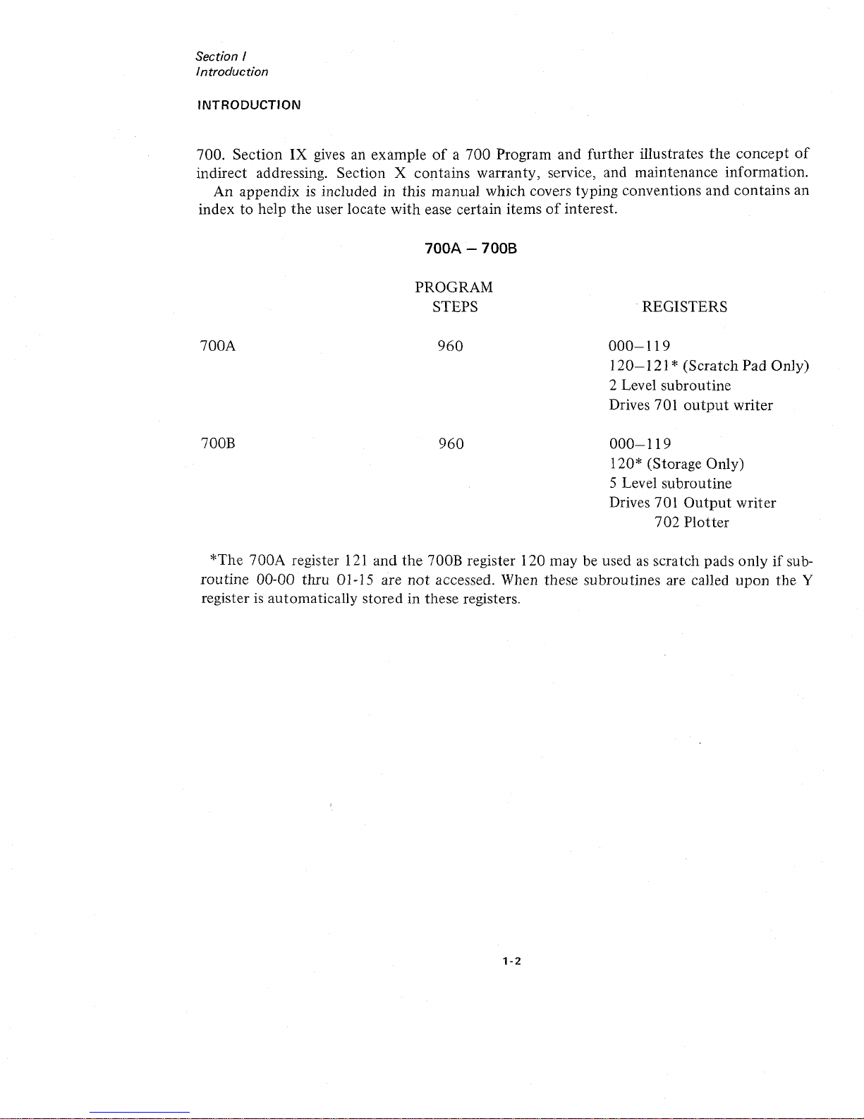
700. Section
IX
gives an exampleofa
700
Program and
further
illustrates
the
concept
of
indirect addressing. Section X contains warranty, service, and maintenance information.
An appendix
is
included in this manual which covers typing conventions and contains an
index
to
help
the
user locate
with
ease certain itemsofinterest.
700A
-7008
700A
700B
PROGRAM
STEPS
960
960
.REGISTERS
000-119
120-121
* (Scratch Pad Only)
2 Level subroutine
Drives 701
output
writer
000-119
120* (Storage Only)
5 Level subroutine
Drives 701
Output
writer
702
Plotter
*The
700A
register
121
and
the
700B register 120 may be usedasscratch pads
onlyifsub-
routine
00-00 thru 01-15 are
not
accessed. When these subroutines are called
upon
the
Y
register
is
automatically stored in these registers.
1-2
Page 13
Section
II
ExplanationofKeys
o 0
!lflllll
I
•••
0000
LEARN
LIST
PRINT
PROGRAM
LEARN
RUN
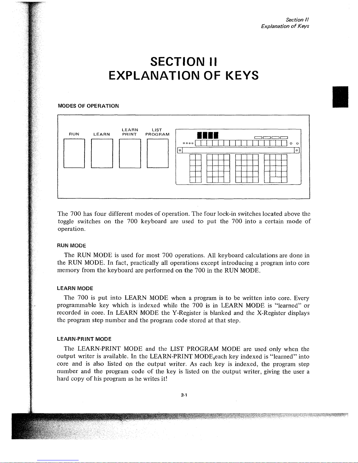
MODES
OF OPERATION
The
700
has
four
different modesofoperation.
The
four
lock-in switches located above the
toggle switches
on
the
700
keyboard are used
to
put
the
700
into
a certain
mode
of
operation.
RUN MODE
The
RUN MODE is used
for
most
700
operations. All keyboard calculations are done in
the RUN MODE.
In
fact, practically all operations
except
introducing a program
into
core
memory from
the
keyboard
are performedonthe
700 in the RUN MODE.
SECTION II
EXPLANATION
OF KEYS
LEARN MODE
The
700isput
into
LEARN MODE when a program istobe written
into
core. Every
programmable
key
which is indexed while
the
700
is in LEARN MODEis"learned"
or
recorded in core. In LEARN MODE
the
Y-Register is blanked and the X-Register displays
the program
step
number
and
the
program code storedatthat
step.
LEARN-PRINT MODE
The
LEARN-PRINT MODE and
the
LIST PROGRAM MODE are used
only
when the
output
writer is available.Inthe
LEARN-PRINT MODE,each key indexed is
"learned"
into
core
and
is also listed
Or
the
output
writer. As each
key
is indexed,
the
program step
number
and
the
program codeofthe
keyislisted
on
the
output
writer, giving
the
user a
hard
copyofhis program ashewrites it!
2-1
Page 14
Section
II
ExplanationofKevs
LIST-PROGRAM MODE
When
the
700isput
in the LIST-PROGRAM MODE and the GO keyisdepressed, it
automatically lists the program steps and program code in increments
of
100
steps until
it
encounters
an END PROGRAM code.
The
LEARN-PRINT and LIST-PROGRAM modes
are discussed in greater detail in
the
701 OUTPUT WRITER MANUAL.
TURNING
THE
700
ON
The procedure for turning the 700onconsistsofthree steps:
1.
Turn power switch ON.
2.
Index
PRIME to initialize the system.
3.
Select
mode
of
operation. (In
most
instances the R UN
mode
will be selected.
Depress R UN
button.)
The
Wang
700
is nowinRUN MODE readytoperform
your
calculations.
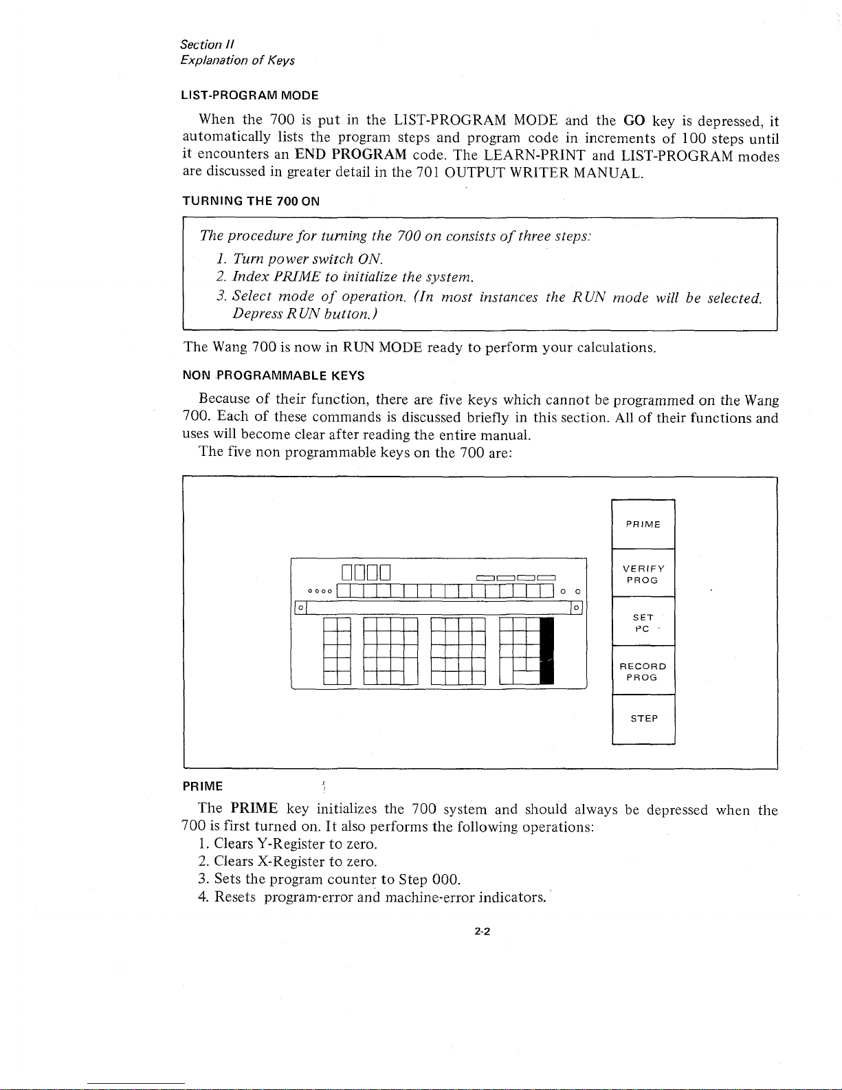
NON
PROGRAMMABLE
KEYS
Becauseoftheir
function, there are five keys which
cannot
be programmedonthe Wang
700.
Eachofthese commandsisdiscussed briefly in this section. Alloftheir functions and
uses will
become
clear after reading
the
entire manual.
The
five
non
programmable keysonthe
700
are:
PRIME
DODD
I
II
II
II
I
0000
0
0
G
EJ
,
,
PRIME
VERIFY
PROG
SET
PC
.
RECORD
PROG
STEP
The
PRIME key initializes the
700
system and should always be depressed when
the
700isfirst
turned
on.Italso performs
the
following operations:
1.
Clears V-Registertozero.
2.
Clears X-Registertozero.
3. Sets
the
program
countertoStep 000.
4.
Resets program-error and machine-error indicators.
2-2
Page 15
Section
/I
Explanation
of
Keys
The PRIME key should be depressed
when
the
700
is first
turned
on.
NOTE
The PRIME
key
should
notbedepressed when any operationisbeing executed.
If
the programisto be
stopped
during execution, the STEP
key
should
be used. This
will
stop
the program after
the
current stepisexecuted.
Also
indexing the PRIME
key
when RECORD PROGRAM
or
LOAD PROGRAM
commands
are being
executed
will cause
difficulty
with
the tape.
If
the PRIME
keyisindexed
accidentally during a RECORD PROGRAM or LOAD PROGRAM operation, the
operation
will be terminated immediately. However, the tape should be
rewound
before executing any
other
tape operations.
PROGRAM
COUNTER
AND
SET
PC
The
program
counterorPCisa
counter
which
counts
from
000to959.Itindicates which
program step
is
about
to
be executed.
At
all times,italways
pointstothe
next
program
step. Thus,
when
the
machine is performing step 108,
the
PCisalready
on
step 109.
The SET
PC
key
allows
the
usertoaddress and set
the
program
counter
with
the
next
three keystrokes.
SET
PC
018
This instruction sets
the
program
countertoprogram step
number
018.Toset
the
program
counter
requires
four
keystrokes: SET PC followed by three numeric keys. PRIME auto-
matically sets
the
program
countertostep
number
000.
STEP
The
STEP key allows
the
user
to
step
through
his program
one
stepata time.Ifthe
programisrunning when
the
STEP keyisindexed,
the
program
stopsatthe
stepitis
about
to execute. In
the
RUN MODE, depressing the STEP
key
will cause
the
700toperform
the
next
step in
the
program. Each time
the
STEP
key
is indexed,
the
next
program step will be
executed.
The GO key will take
the
700
out
of
the
stepping
mode
and
putitin
the
continuous
mode
executing
the
remaining steps in
the
program
until
a STOP
commandisencountered.
NOTE
In any 2-step
command
such
as
DIRECT ADDRESSING and WRITE ALPHA
commands, the GO
key
should
not
be depressedinthe middle
of
the 2-step
command. The entire 2-step
command
should be
executedinstep
mode
before
switching to the
continuous
mode.
This stepping featureisof
tremendous
value for debugging programs.
The
programmer
can
step
through
his program and locate his difficulty immediately.ByswitchingtoLEARN
2-3
Page 16
Section
II
ExplanationofKeys
MODE
he
can
see
the
step
number
and
the
codeofthe
operationheis
abouttoexecute.
When
stepping
through
a program in
LEARN
MODE,
the
program
step
number
(the
PC)
and
the
program
code
of
the
operation
is displayed in
the
X-Register. However, in
LEARN
MODE
the
operationisnot
executed.
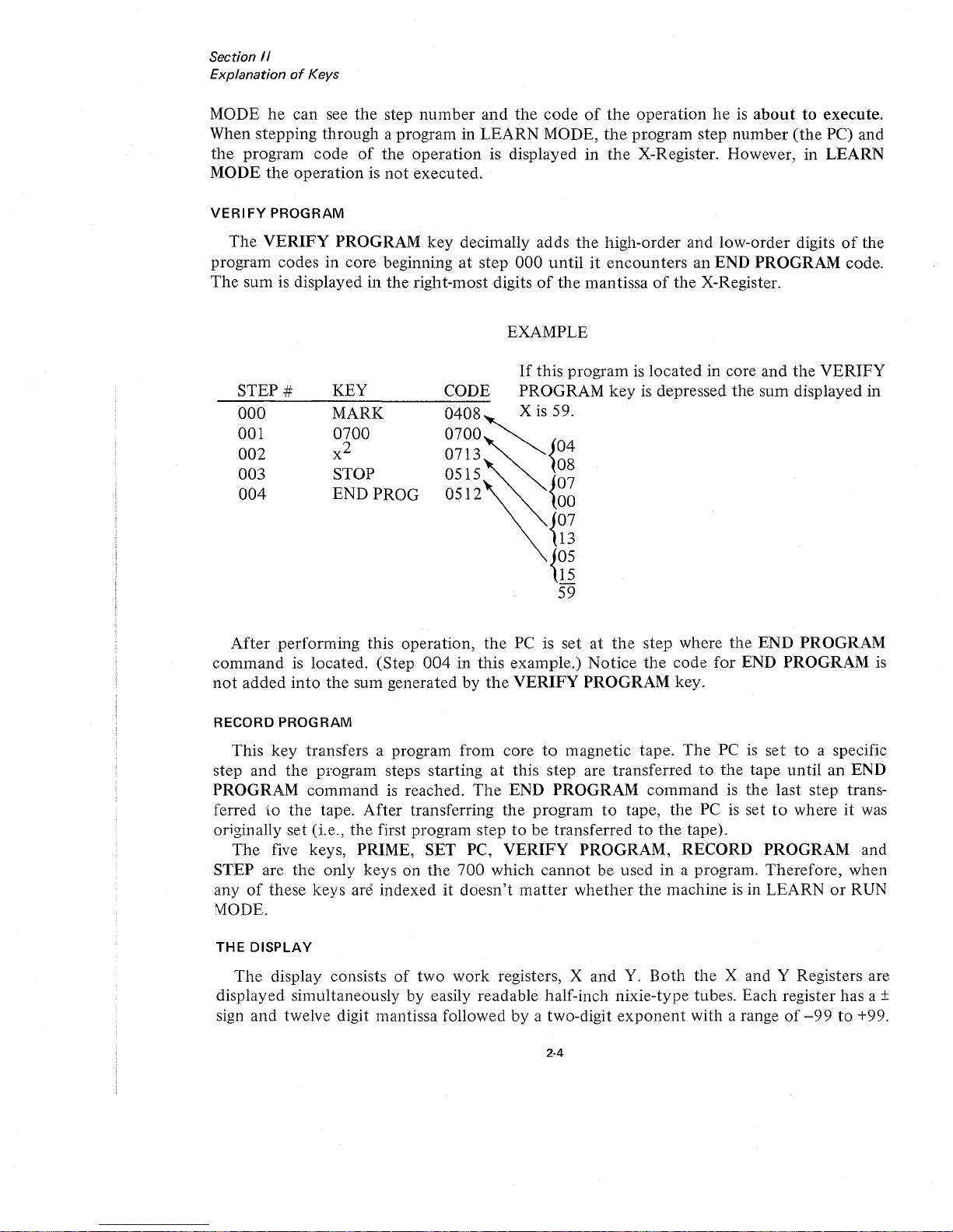
VERIFY
PROGRAM
The
VERIFY
PROGRAM
key
decimally adds
the
high-order
and
low-order
digitsofthe
program codes in core beginning
at
step
000
untilitencounters
an END
PROGRAM
code.
The
sum is displayed in
the
right-most digitsofthe
mantissaofthe
X-Register.
EXAMPLE
STEP
#
000
001
002
003
004
KEY
MARK
0700
x
2
STOP
END PROG
CODE
0408
0700
0713
0515
0512
If
this
programislocated
in core
and
the
VERIFY
PROGRAM
key
is depressed
the
sum
displayed in
X
is
59.
04
08
07
00
07
13
05
15
-
59
After
performing
this
operation,
the
PC is setatthe
step where
the
END
PROGRAM
command
is located. (Step
004inthis
example.)
Notice
the
code
for
END
PROGRAM
is
not
added
into
the
sum generatedbythe
VERIFY
PROGRAM
key.
RECORD
PROGRAM
This
key
transfers a program from coretomagnetic
tape.
The
PCisset
to
a specific
step
and
the
program steps startingatthis step are
transferredtothe
tape
untilanEND
PROGRAM
commandisreached.
The
END
PROGRAM
commandisthe
last step trans-
ferred
to
the
tape.
After
transferring
the
program
to
tape,
the
PCissettowhereitwas
originally
set
(i.e.,
the
first program steptobe
transferredtothe
tape).
The
five keys, PRIME, SET PC,
VERIFY
PROGRAM,
RECORD
PROGRAM
and
STEP are
the
only
keys
on
the
700
which
cannot
be used in a program.
Therefore,
when
anyofthese
keys
are
indexeditdoesn't
matter
whether
the
machine is in
LEARNorRUN
MODE.
THE
DISPLAY
The
display consists
of
two
work
registers, X
and
Y.
Both
the
X and Y Registers are
displayed simultaneously by easily readable half-inch
nixie-type
tubes. Each register has a +
sign
and
twelve digit mantissa followedbya two-digit
exponent
with a range
of
-99to+99.
2·4
Page 17
+.
XXXXXXXXXXXX
+.
XXXXXXXXXXXX
\ I
mantissa
I
floating decimal
sign
of
mantissa
Section
/I
ExplanationofKeys
+ X X (Y-Register)
+ X X (X-Register)
\
'exponent
signofexponent
For
numbersinthe
range
.1~INI
< 1
000000000,
the
decimal
point
retains
its
natural
position.
When a
number
lies
outside
this
range,
the
decimal
automatically
relocatestothe
extreme
left,
and
the
exponent
of
the
power
of
lOis
indicated
correctly
in
modified
scientific
notation.
This
property
will
become
clear
after
a few
minutes
familiarization
with
the
keyboard.
(A few
numbers
and
how
they
appearinthe
display
are
given below.)
X-REGISTER
The
keys0,1, 2,
...
9 and
decimal
point
(.)
are used
for
enteringanumber
into
the
X-Register.
The
SETEXP
keyisusedtoset
the
exponent
valueofX.
The
CH SIGN
key
changes
the
algebraic signofthe
mantissaorexponent
of
X.
Indexinganumber
into
the
700
keyboardisas
simple as writing
the
number
down
on
paper.
The
normal
sequence
of
stepsisto
key in
the
mantissa
followed
by
the
SETEXP
key
and
the
valueofthe
exponent.
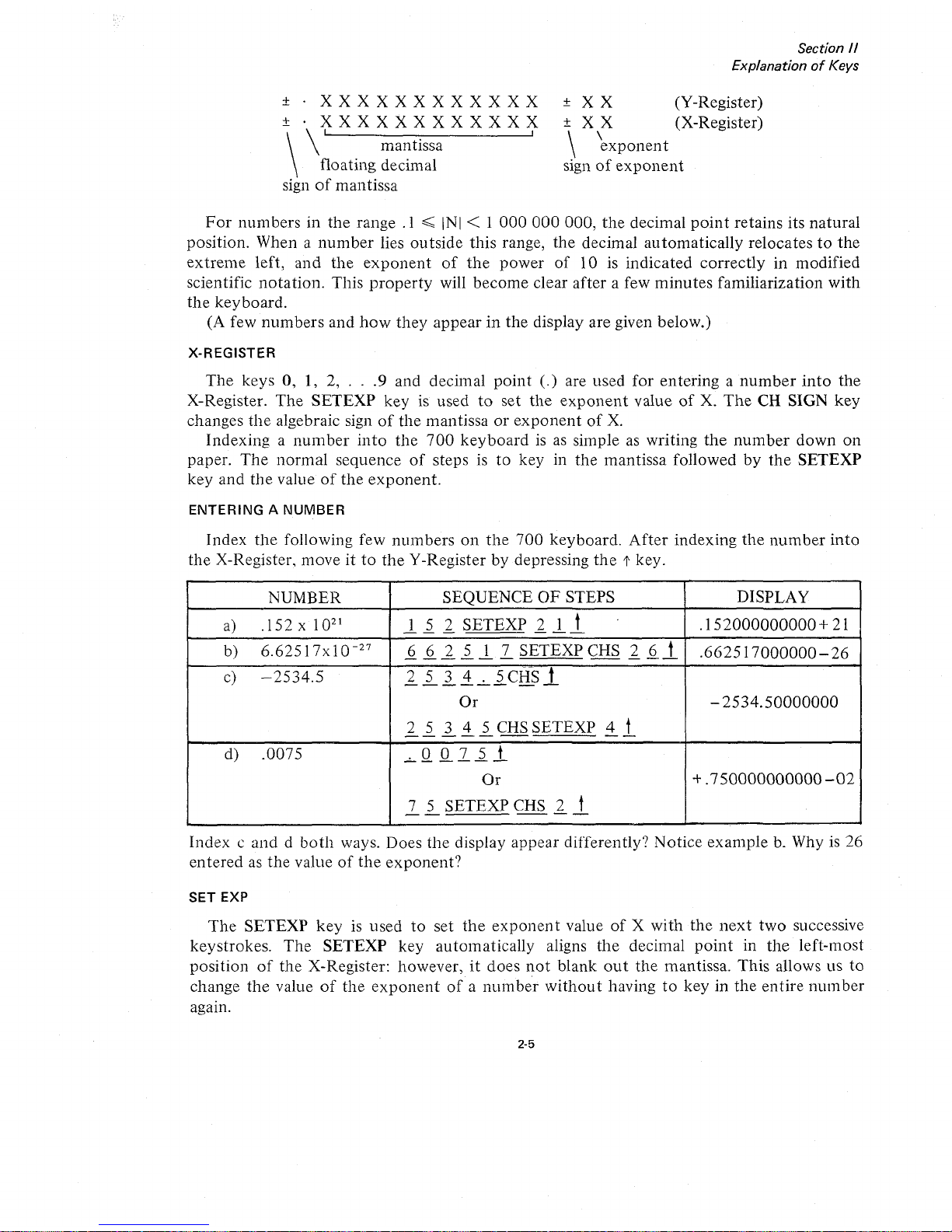
ENTERINGANUMBER
Index
the
following few
numbers
on
the
700
keyboard.
After
indexing
the
number
into
the
X-Register.
moveitto
the
Y-Registerbydepressing
the
t key.
NUMBER
SEQUENCE
OF
STEPS DISPLAY
a)
.152x10
21
1
5 2
SETEXP
2 1 t
.
.152000000000
+ 21
--
-
---
b)
6.62517x
10
-27
6 6 2 5 1
7
SETEXP
CHS
2 6
t
.662517000000-26
------
---
c)
-2534.5
2 5 3 4 . 5 CHS t
------
--
Or
-
2534.50000000
2 5 3 4 5 CHS
SETEXP
4 t
-----
--
d)
.0075
.0075t
------
Or
+.750000000000-02
7 5
SETEXP
CHS
2
t
--
--
Indexcanddboth
ways. Does
the
display
appear
differently?
Notice
example
b. Whyis26
enteredasthe
valueofthe
exponent?
SET EXP
The
SETEXP
keyisused
to
set
the
exponent
valueofX
with
the
next
two
successive
keystrokes.
The
SETEXP
key
automatically
aligns
the
decimal
point
in
the
left-most
positionofthe
X-Register: however,itdoes
not
blank
out
the
mantissa.
This
allows us
to
change
the
valueofthe
exponent
ofanumber
without
havingtokeyinthe
entire
number
•
agam.
2-5
Page 18

Section
II
ExplanationofKeys
EXAMPLE
Index 1.75 x 10
23
Suppose
the
following sequenceofstepsisused:
1 . 7 5 SETEXP 2 3
Notice what happens to
the
decimal
point
when
the
SETEXP key
is
indexed.Itis
not
necessarytoindex the decimal
point,asthe SETEXP key automatically alignsitin
the
left
most position. The value
of
the
exponent
will also have
to
be indexed correctly.Ifthe
number
is in
proper
scientific
notation,
the valueofthe
exponentissimply increased by
1.
Thus,
the
correct sequenceofsteps would be:
CLEAR X 1 7 5 SETEXP 2 4
All numbers indexed after the SETEXP key simply changes
the
valueofthe
exponent.
Since
the
rangeofthe
exponentis-99
to
+99, normally only Ior2 numbers are indexed after
the
SETEXP key. However, if more
than
2 numbers are indexed, the
exponent
takesonthe
value
of
the
last 2 numbers entered.
EXAMPLE
If
the following sequenceofsteps is performed:
1.
1 2 SETEXP 2 3
4,
the valueofthe
exponentis34.
2.
For
SETEXP CHS 3
57,
the valueofthe
exponentis-57.
3.
For
SETEXP 5 0 2,
the
value
of
the
exponent
should be 2. However,
on
the
display
the
exponent
would be blanked
out
and the decimal
point
would assume
its
natural
position.
The
700
will remain in the SETEXP
mode
until a
non
numeric
key
or the decimal
point
key
is depressed.
V-REGISTER
The
Y-Registerisanother
work
register used in conjunction
with
the
X-Register for basic
arithmetic operations and
data
transfers. A
number
in the X-Register can easily be trans-
ferred
to
the
Y-Register by indexing
the
t key
or
~
t key.
KEYSTROKE
CLEAR X
f
~
U
+
x
OPERATION
Clears X-Register
X
into
Y, X unchanged
Y into X, Y unchanged
X and Y exchanged
Y
+X in
to
Y, X unchanged
Y-X
into
Y, X unchanged
Yx X into Y, X unchanged
2-6
Page 19
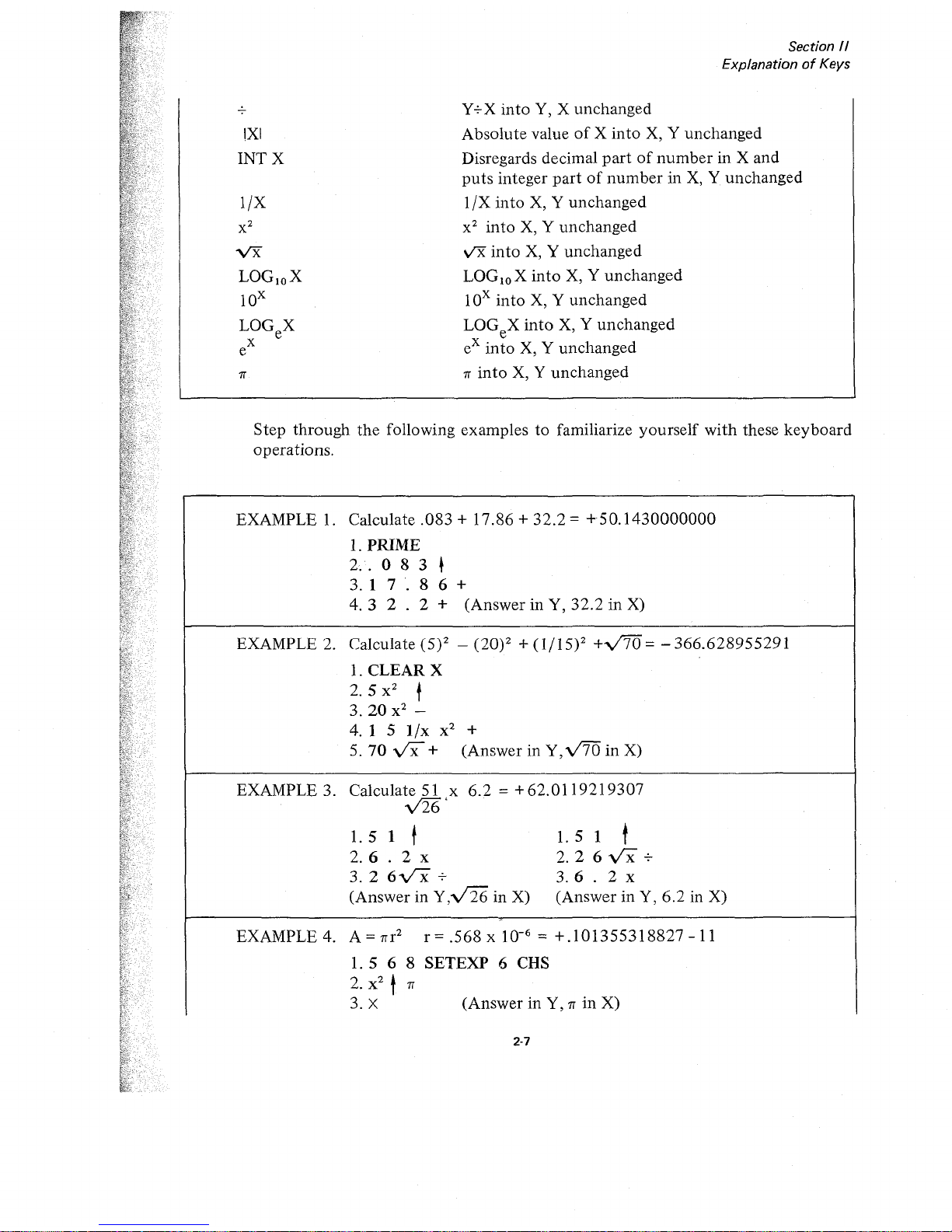
2-7
Step
through
the
following
examplestofamiliarize
yourself
with
these
keyboard
operations.
Y+X
into
Y, X
unchanged
Absolute
valueofX
into
X, Y
unchanged
Disregards decimal
partofnumberinX
and
puts
integer
partofnumberinX, Y
unchanged
1/X
into
X, Y
unchanged
x2into
X, Y
unchanged
v'X
into
X, Y
unchanged
LOGloX
into
X, Y
unchanged
lOx
into
X, Y
unchanged
LOGeX
into
X, Y
unchanged
eX
into
X, Y
unchanged
rr
into
X, Y
unchanged
Section 1/
ExplanationofKeys
•
•
rr
!XI
INTX
l/X
EXAMPLE 3. Calculate 51 x
6.2
= +
62.0119219307
y'26'
1.51
t
1.51
t
2. 6 . 2 x
2.
2 6
vx
+
3. 2
6-vx
+
3.6
. 2 x
(AnswerinY,v126
in X)
(AnswerinY,
6.2
in X)
EXAMPLE 2. Calculate (5)2 - (20)2 +
(1/15)2
+V'70
= -
366.628955291
1.
CLEAR
X
2.
5 x
2
t
3.20
x
2
-
4. 1 5
l/x
x
2
+
5.70
vx+
(AnswerinY,v'70
in
X)
EXAMPLE
4.
A=rrr
2
r=.568x
10-
6
=
+.101355318827-11
1.5
6 8
SETEXP
6 CHS
2.
x
2
t
rr
3. X
(AnswerinY,rrin
X)
EXAMPLE
1.
Calculate.083+
17.86+32.2=
+50.1430000000
1.
PRIME
2.·.083~
3. 1
7.
8 6 +
4.3
2 . 2 +
(AnswerinY,
32.2inX)
vx
LOGloX
lOx
LOGeX
x
e
Page 20
,
\
,
,
;i
.
•
Section
II
ExplanationofKeys
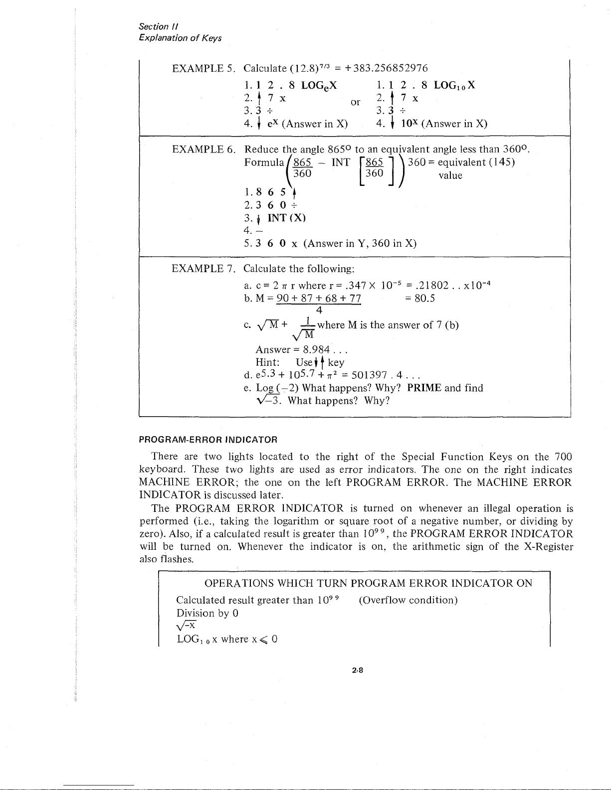
EXAMPLE 5. Calculate (12.8)?/3 = +
383.256852976
1.
1 2 . 8 LOGeX
1.
1 2 . 8 LOG! 0 X
2. t 7 x
or
2.'
7 x
3.3
+
3.3+
4. t
eX
(Answer in
X)
4.
~
lOX
(Answer in
X)
EXAMPLE 6. Reduce
t~e
angle 8650to
an equivalent angle less than
360
0
.
Formula
865 - INT
~865';
360
=equivalent
(145)
360
360
value
'.
- - /
1.
865
t
2.3
6 0 +
3.
tINT
(X)
4.-
5.3
6 0 x (Answer in Y,
360
in X)
EXAMPLE 7. Calculate
the
following:
a.
c = 2 T( r where r = .347 X
10-
5
=
.21802..xlO-
4
b.
M =
90
+ 87 + 68 + 77 =80.5
4
c.
y'"M+ 1 where M
is
the
answerof7 (b)
y'M
Answer =
8.984
...
Hint: Use+tkey
d. e
5.3
+ 10
5.7
+
T(2
=
501397.4...
e.
Log
(-.
2) What happens? Why? PRIME and find
vC3.
What happens? Why?
PROGRAM-ERROR
INDICATOR
There are two lights located
to
the
right
of
the
Special
Function
Keys
on
the 700
keyboard. These two lights are used
as
error
indicators.
The
one on the right indicates
MACHINE
ERROR;
the
one
on
the
left PROGRAM
ERROR.
The
MACHINE
ERROR
INDICATOR is discussed later.
The
PROGRAM
ERROR
INDICATORisturned
on
whenever an illegal
operation
is
performed (i.e., taking the logarithmorsquare
rootofa negative number,ordividing by
zero). Also,
if
a calculated result is greater
than
10
99
, the PROGRAM
ERROR
INDICATOR
will be
turned
on. Whenever
the
indicatorison,
the
arithmetic sign
of
the
X-Register
also flashes.
OPERATIONS WHICH TURN PROGRAM
ERROR
INDICATOR ON
Calculated result greater
than
10
99
Division by 0
y:::x
LOG!oXwhere
x<
0
(Overflow condition)
2·8
Page 21
Section
II
ExplanationofKeys
Log e where
x<
0
Searching Non-Existent Flag (See page 4-3).
Addressing An Illegal Data Register (Any Register Greater
than
121)
Program Overlaps Core (See BYPASSING PROGRAM BLOCKS page 6-8)
Program Block
is
Missing
An
END PROGRAM
Instruction
(See
Definition
of
PROG RAM BLOCK(page 6-4)
The PRIME key
is
usedtoturn
the
PROGRAM
ERROR
INDICATOR off. In program-
Illing, a SKIP
IF
ERROR
commandisavailabletotest for this condition. Performing this
il'st will also
turn
the
indicator off.
DATA
STORAGE
REGISTERS
[n additiontothe
X and Y
work
registers, the Wang
700
hasupto
122 storage registers.
I
':ach
register has a 12-digit mantissa with sign and a two-digit
exponent
with sign.
The
registers are
numbered
consecutively from
000to121 and canbeaddressed
both
directly
;Ind
indirectly for
maximum
convenience. Numbers are stored from and recalledtothe
X-
Register. Each register can be usedtoadd, subtract, multiply and divide. Any
number
in
storage can be exchanged
or
swapped with any
numberinthe
X-Register.
DIRECT
ADDRESSING
Direct addressingofregisters requires a two-step command.
The
first keystroke indicates
lile
operation
(i.e.,
to
Store, Recall, Add, Subtract, Multiply, Divide,
or
Exchange).
The
second keystroke indicates
the
register in which the operationisto
be performed.Tostore a
nllmber, simply index the control key STORE DIRECT followed by a second keystroke
Identifying
the
register number.
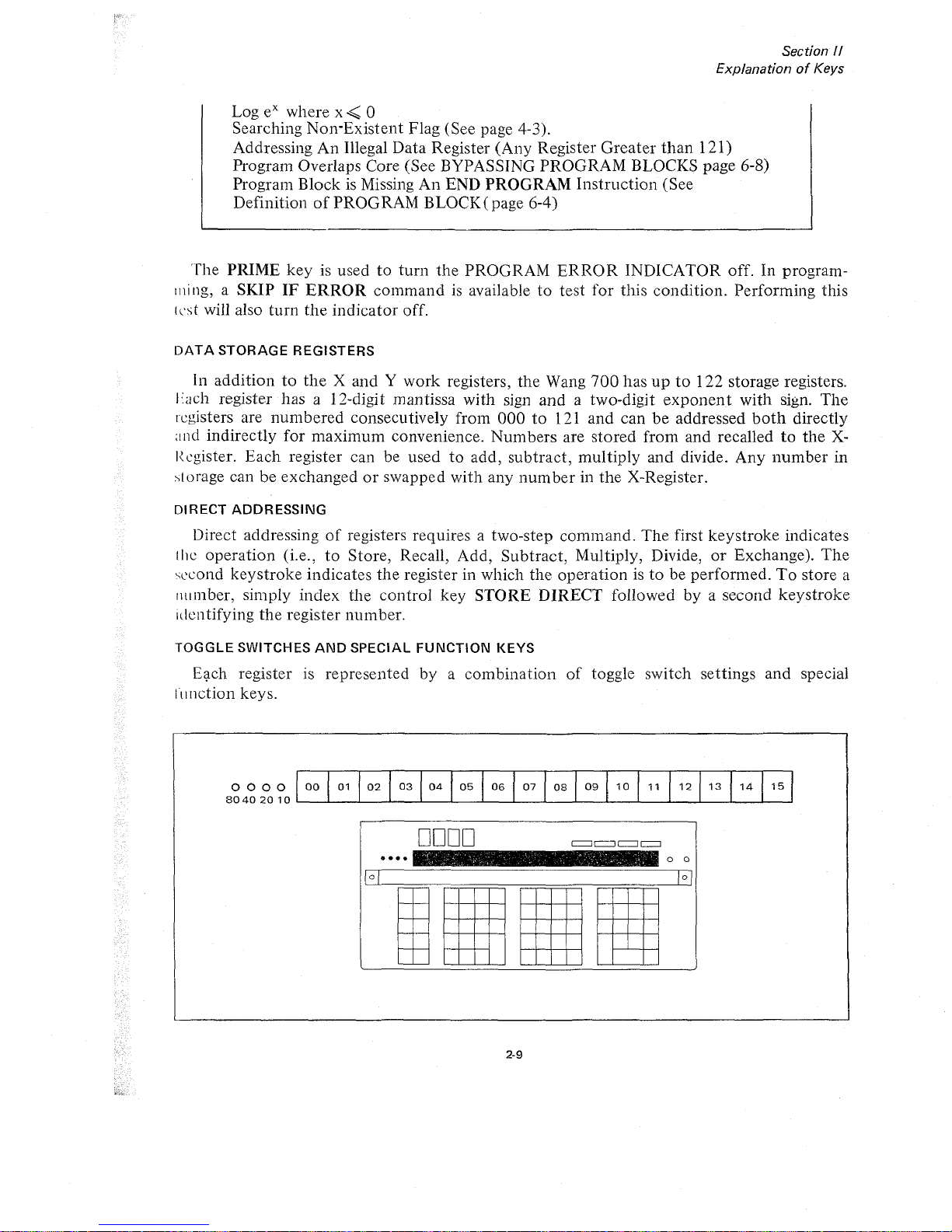
TOGGLE
SWITCHES
AND
SPECIAL
FUNCTION
KEYS
Eqch register is represented by a combination
of
toggle switch settings and special
III
nction keys.
0000
80402010
00
01
02
03
04
05 06
07
08
09
10
11
12
13
14
15
••••
DODD
2-9
It
o 0
Page 22
....
-_
~--
-"
..
''- "
..
--
'
2-10
Section
II
ExplanationofKeys
15
14
12
13
o 0
o 0
1 1
09
10
IltllllJ
I
Ii
II
II
•
•
, ,
~
. a .....
.
-~...,
DODD
DODD
••••
••••
:;:::::;::::::::::
00
01
02 03
Wf
05
06 07
08
09
10 1 1 1 213
14
1 5
;.:
.;.:-
:.:.:
<.:.
gg
01
02 03 04 05 06
••.•
·.0
.••.
:.1..................
08
..................
_---L_-'--_I....-..--L_--l.-_~=_---L_-'--_I....-__l._----L_..l.-----'L---'
0080
80402010
BoBO
80402010
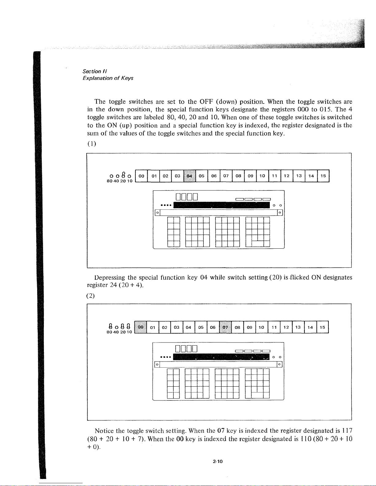
Notice
the
toggle switch setting. When the07keyisindexed the register designated is 117
(80
+ 20 + 10 + 7). When the
00
keyisindexed the register designated
is
110 (80 + 20 +
10
+
0).
The
toggle switches are set
to
the
OFF
(down) position. When
the
toggle switches are
in
the
down
position,
the
special function keys designate
the
registers
000to015.
The
4
toggle switches are labeled 80, 40,
20
and 10. When
oneofthese toggle switches is switched
to
the
ON
(up)
position and a special function key is indexed,
the
register designated is the
sum
of
the
valuesofthe
toggle switches and
the
special
function
key.
(1)
Depressing the special function
key04while switch setting
(20)
is flicked ON designates
register
24
(20
+ 4).
(2)
Page 23
o 0
o 0
CI
:::J
£=Ji
11
1
I
I[
II
Il~
.
. . - .
......
',.,
.
~
. ..
DODD
0000
••••
••••
00
01
:j!,III!
03
04
05
06
07 08
0910
1
1 1
2
13
1
4 1 5
00
01
02
03
04
05
06
07
08
09
10 11
i~~[·i:1
13 141
5
oong
80402010
Section
/I
ExplanationofKeys
2-11
oogo
80402010
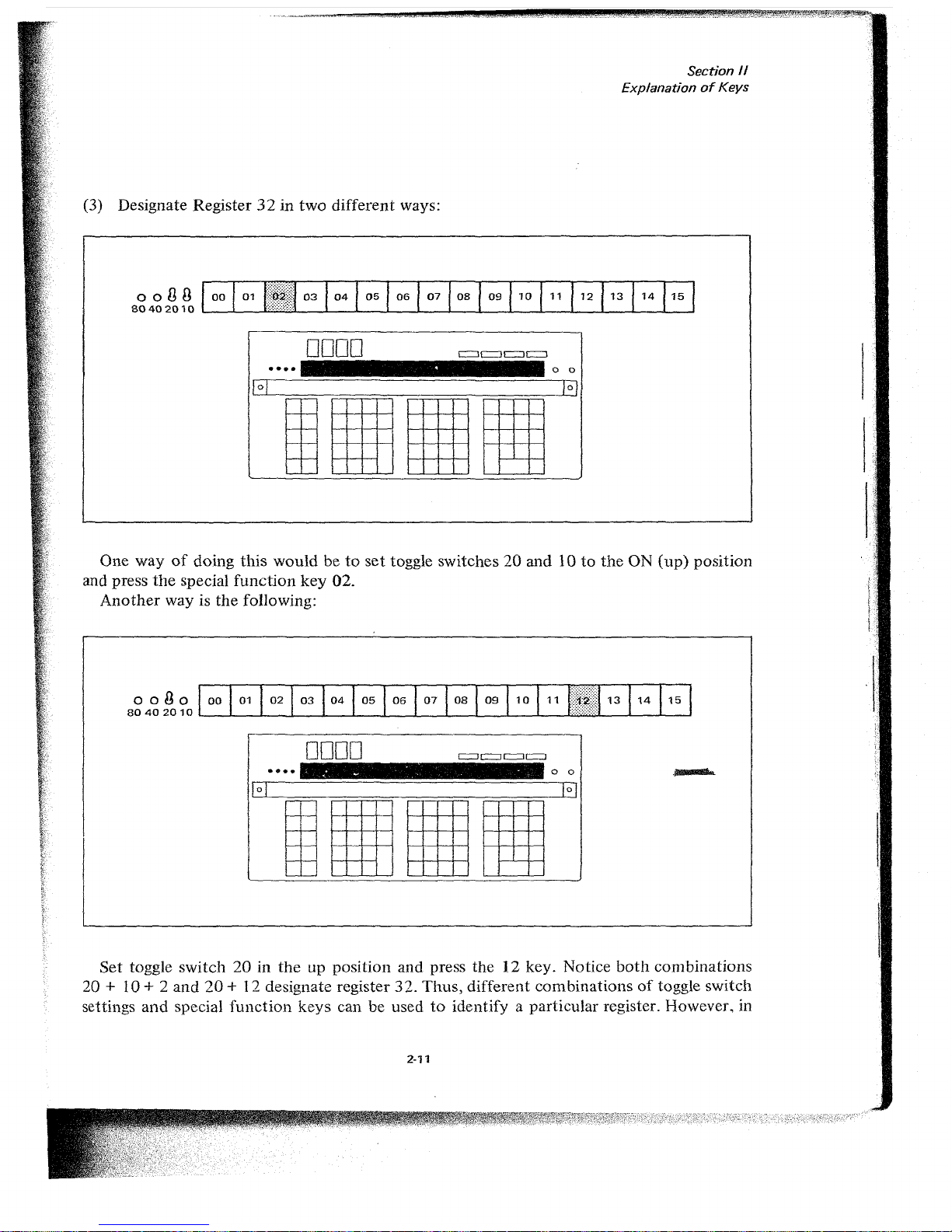
(3) Designate Register32in
two
different ways:
One way
of
doing
this
wouldbeto
set
toggle switches20and10to
the
ON
(up)
position
and press
the
special
function
key
02.
Another
way is
the
following:
Set
toggle
switch
20inthe
up position and press
the12key. Notice
both
combinations
20 + 10 + 2
and
20
+ 12 designate register
32.
Thus,
different
combinationsoftoggle switch
settings
and
special
function
keys
can be usedtoidentify a particular register. However. in
J:'
-
_.'
,,,.
-
';~
,
-,<'-
Page 24
Section
II
ExplanationofKeys
LEARN
MODE
the
program
code
designating Register32wouldbe0302or0212,
depend-
ing
on
which
method
was used.
STORE
DIRECT
To
storeanumber
in a register, simply
index
the
number
into
the
X-Register, press
the
STORE
DIRECT
key
followed by
the
register
number.
EXAMPLE
1:
EXAMPLE 2:
Store
1r2into
register 14
* Toggle switches
down
Index1rx2STORE
DIRECT
14
1r
2 is
now
stored
in register 14
andisstill
displayed in
the
X-Register.
Store
.57 x 1018into
Register
32
*Toggle switches20and 10 UP
Index
5 7
SETEXP
1 8
----
--
STORE
DIRECT
02
.57 X 1018is
now
storedinRegister32and
is still displayed in
X.
i
*
NOTE
For problems requiring less than
17
storage registers and for general usage, the
toggle switches
are
kept
in
the OFF
(down)
position and the Special
Function
Keys are used to address Registers
000
to 015.
RECALL
DIRECT
RECALL
DIRECT
recalls the
number
from
the
designated register
into
the
X-Register.
The
number
appears in
the
X-Register
and
also remains in
the
storage register.
The
sequence
of
stepstofollow is
the
same as
with
STORE
DIRECT.
I
EXAMPLE: Recall1r2
from
register 14
Index
RECALL
DIRECT
14
1r2appears in
the
X-Register and is still
in
storage register 14.
2·12
Page 25

Section
1/
ExplanationofKeys
~
-.....
DIRECT,
The
-:
DIRECT
key
is a
handy
command
which allows
the
operator
to
exchange
a
number
in
the
X-Register
withanumber
in anyofthe
storage registers.
The
command
simply swaps
the
valuesofthe
X-Register
and
the
internal register. Again
the
sequence
of
stepstofollow is
-:
DIRECT
followedbythe
desired register.
EXAMPLE:
Suppose
27.8 is in
the
X-Register
and
1f2
is
in Register 14.
To
store 27.8 in Register 14
and
reca1l1f2to
the
X-Register in
one
operation:
Index
~
DIRECT
14
•
+DIRECT
Adds
number
in
X-REGISTER
to
value
stored
in register designated by
next
keystroke.
TheXand
Y Registers remain
unchanged.
-DIRECT
Subtracts
numberInX-REGISTER
from value
stored
In register designated
by
next
keystroke.
TheXand
Y Registers
remain
unchanged.
XDIRECT
Multiplies
numberinX-REGISTER
by
value
stored
in register designated
by
next
keystroke.
TheXand
Y Registers
remain
unchanged.
-:-DIRECT
Divides
numberinX-REGISTER
into
number
stored
in register designated
by
next
keystroke.
TheXand
Y Registers
remain
unchanged.
What
happensifthe
same
operationisperformed
again?
ADD,
SUBTRACT,
MULTIPLY,
AND
DIVIDE
DIRECT
(The X and V Registers Remain Unchanged.)
In
addition
to
storingal2-digit
mantissa and a 2-digit
exponent,
the
registers
can
be
lIsed as
accumulators
to
add,
subtract,
multiply
and
divide. With
eachofthese
operations
the
resultisstored
in
the
designated register and
the
X-Register
and
Y-Register
remain
ullchanged.
The
four
arithmetic
operations
are'
A simple
example
will
illustrate
how
eachofthese
commands
works.
EXAMPLE:
Perform
the
following in Register 001
(13
x2)
+ 4
-3=7
3
1.
1 3
STORE
DIRECT
01
Places 13 in Register
01
--
and
the
X-Register
2.
2 X
DIRECT
01
This
sequenceofsteps
-
-
places
the
product
equal
to26in Register
Oland
2 remains
unchangedinthe
X-Register.
3. 4 +
DIRECT
01
Adds4to
the
Answer.
-
30isnowinRegister 01,
4 is
in
X-Register.
2-13
Page 26
Section
II
ExplanationofKeys
4. 3 -;.-DIRECT 01
-
5. -
DIRECT
01
6.
RECALL
DIRECT
01
Divides
resultby3
pu
tting
lOin
Register 01,
3
remainsinX-Register.
Since
3 is in X
when
the
commandisgiven,
3 is
subtracted
from
10
putting
7 in
Register 01,
3 in X-Register.
Recalls final answer
to
X. = 7
The
fact
that
the result is
put
in
the
storage register
rather
than
the X-Register can
be
extremely
usefulifwe are using a
constant
multiplierordivisor.
INDIRECT
ADDRESSING
In
addition
to
providing
direct
access
to
the
internal
storage registers,
the
Wang
700
offersanindirect
modeofaddress.
Both
display registers are utilized
for
indirect
addressing.
The
Y-Register designates
the
register being addressed. As
with
direct
addressing,
the
X-Register is used as
the
work
register.
The
commandisperformedonthe
number
in X
and
the
result
is placedinthe
internal
storage register.
Indirect
addressingisa valuable
programming
tool
for
saving program steps, especially in
repetitive
matrix-type
operations.
Remember,
indirect
addressing requires
only
one
step -
the
operation
itself.
The
register
on
which
the
operationisperformed
is identifiedbythe
number
in Y.
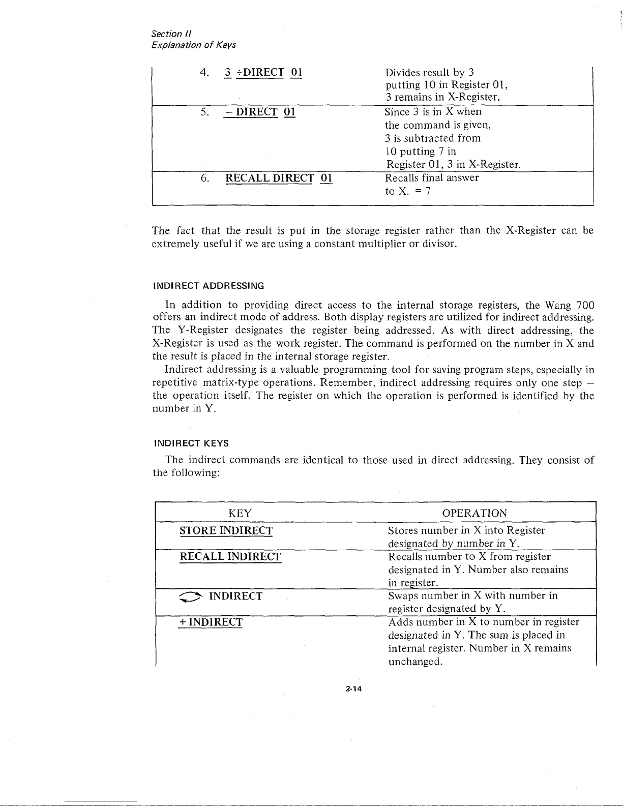
INDIRECT
KEYS
The
indirect
commands
are identicaltothose
usedindirect
addressing.
They
consist
of
the
following:
KEY
OPERATION
STORE
INDIRECT
Stores
number
in X
into
Register
designated by
numberinY.
RECALL
INDIRECT
Recalls
numbertoX from register
designated in Y.
Number
also remains
in register.
:>
INDIRECT
Swaps
number
in X
with
number
in
,
register designated by Y.
+
INDIRECT
Adds
number
in Xtonumber
in register
designated in Y.
The
sum is placed in
internal
register.
Number
in X remains
unchanged.
2-14
Page 27
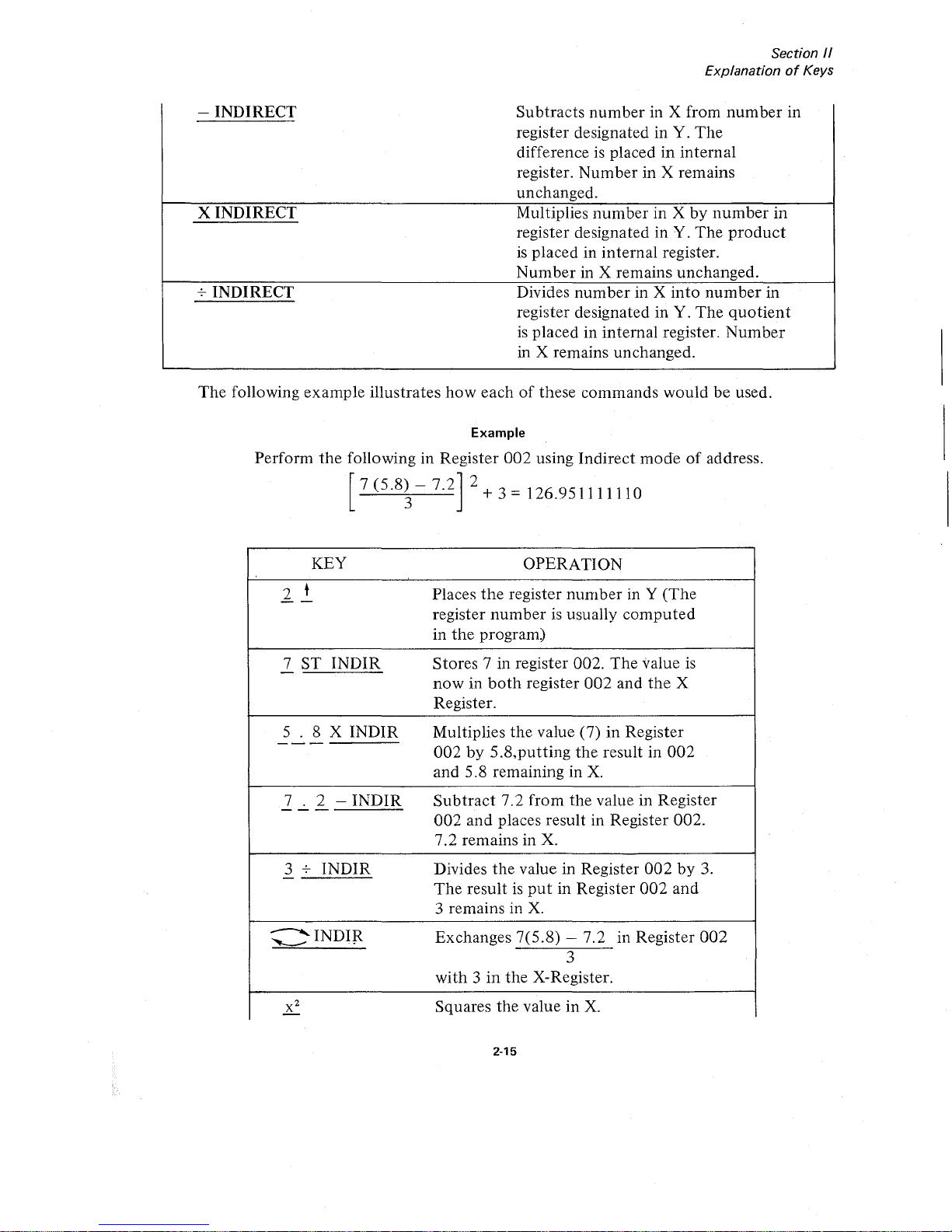
- INDIRECT
X INDIRECT
-;-
INDIRECT
Section /I
ExplanationofKeys
Subtracts
number
in X from
number
in
register designated in Y.
The
differenceisplacedininternal
register.
Number
in X remains
unchanged.
Multiplies
number
in Xbynumber
in
register designated in Y.
The
product
is
placed in internal register.
Number
in X remains unchanged.
Divides
number
in X
into
number
in
register designated in Y.
The
quotient
is
placed in internal register.
Number
in X remains unchanged.
The
following example illustrates
how
eachofthese commands
would
be used.
Example
Perform
the
following in Register
002
using
Indirect
modeofaddress.
7(5.8)-7.2
2+
3
=
126.951111110
3
KEY
,
2 t
--
7 ST
INDIR
-
5 . 8 X INDIR
-------
7 . 2 -
INDIR
---
3
-;-
INDIR
-
~
~INDIR
OPERATION
Places
the
register
numberinY (The
register
numberisusually
computed
in
the
program)
Stores 7 in register 002. The value
is
nowinboth
register
002
and
the
X
Register.
Multiplies the value
(7)
in
Register
002by5.8,putting
the
result in
002
and
5.8 remaining in
X.
Subtract
7.2 from the value in Register
002
and places result in Register 002.
7.2 remains in
X.
Divides
the
value in Register
002by3.
The
resultisput
in Register
002
and
3 remains in
X.
Exchanges 7(5.8) - 7.2 in Register
002
3
with3in
the X-Register.
Squares the value in
X.
2-15
Page 28
•
:;.::-'
•
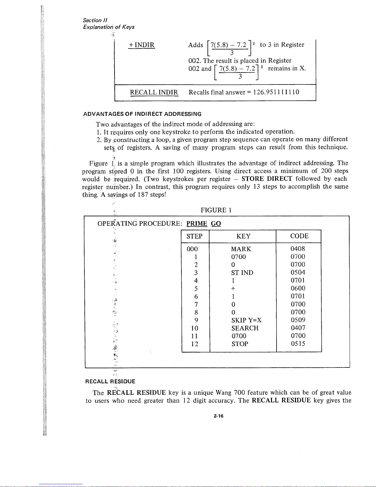
STEP
KEY
CODE
000
MARK
0408
1
0700
0700
2 0
0700
3
STIND
0504
4 1
0701
5
+
0600
6 1
0701
7 0
0700
8 0
0700
9
SKIP Y=X
0509
10
SEARCH
0407
11
0700
0700
12 STOP
0515
2-16
:t
...
~
-.
-
,-"
RECALL
RESIDUE
The
RECALL RESIDUE key is a unique Wang
700
feature which can beofgreat value
to
users who need greater
than
12 digit accuracy.
The
RECALL RESIDUE key gives the
· .
.
}
,-~
...
-"'~
~,
~
..
.'.).
~k'
·
.,......-
.
".-
.
-
~.
·
or·
·
~.
'.
.
,
.'
'..
"
•
, .
.,..
"~
"
.,
·
OPERATING PROCEDURE' PRIME GO
•
·,.'
FIGURE 1
+INDIR Adds 7(5.8) - 7.2 2
to
3 in Register
3
002. The resultisplaced in Register
002 and 7(5.8)
- 7.2 2 remains in
X.
3
ADVANTAGES
OF
INDIRECT
ADDRESSING
Two
advantagesofthe indirect
modeofaddressing are:
1.
It
requires only one keystroketoperform the indicated operation.
2.
By ,constructing a loop, a given program step sequence can operate on
many
different
setll
of
registers. A savingofmany program steps can result from this technique.
~.o:
RECALL INDIR Recalls final answer =
126.951111110
·
-;,.,
<
Section
II
ExplanationofKeys
,<
"
Figure Lis a simple program which illustrates
the
advantageofindirect addressing. The
,
.e.
program stored 0 in the first 100 registers. Using direct access a minimum
of
200 steps
-
.".:
would
betequired.
(Two keystrokes
per
register - STORE DIRECT followed by each
register
nufnber.)
In
contrast, this program requires only
13
stepstoaccomplish the same
thing. A savings
of
187 steps!
,
Page 29
Section
11
ExplanationofKeys
user
the
optionofdouble precision
arithmetic
for addition, subtraction, multiplication, and
division performed
in
any
of
the
storage registers
or
the
X and Y registers. By indexing
the
RECALL RESIDUE key directly
after
performing
oneofthese operations,
another
12 digitsofaccuracyisacquired.
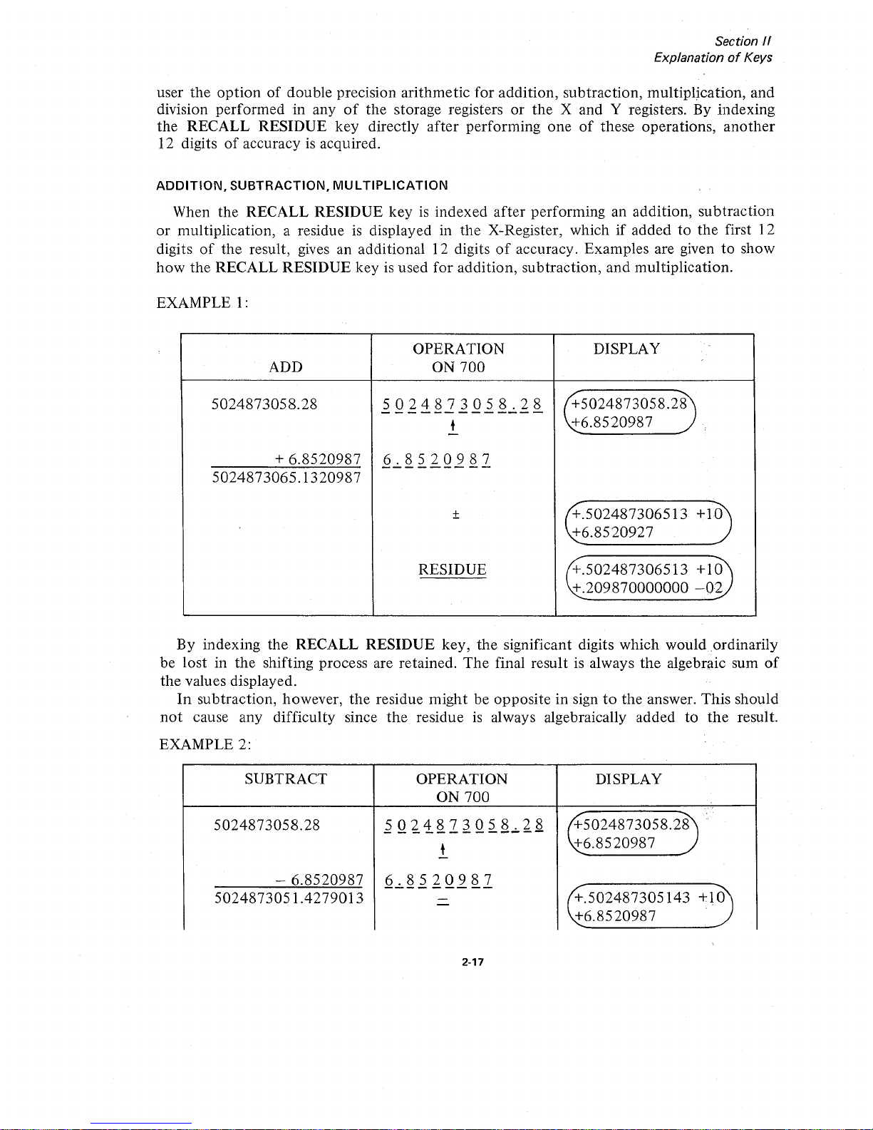
ADDITION,
SUBTRACTION,
MULTIPLICATION
When
the
RECALL RESIDUE
keyisindexed
after
performing an addition,
subtraction
or
multiplication, a residueisdisplayed in
the
X-Register, whichifaddedtothe
first 12
digits
of
the
result, gives an additional 12 digitsofaccuracy. Examples are giventoshow
how
the
RECALL
RESIDUE
keyisused
for
addition, subtraction,
and
multiplication.
EXAMPLE
1:
OPERATION DISPLAY
.
ADD ON
700
5024873058.28
5024873058.28
"+5024873058.28
-------------
t
+6.8520987
-
+
6.8520987
6.8520987
-------
--
5024873065.1320987
+
"+.502487306513 +10
-
•
~6.8520927
RESIDUE
+.502487306513
+10
+.209870000000
-02
By indexing
the
RECALL
RESIDUE
key,
the
significant digits which would ordinarily
be lost in
the
shifting process are retained.
The
final resultisalways
the
algebraic sum
of
the
values displayed.
In
subtraction, however,
the
residue
might
be opposite in signtothe
answer. This should
not
cause any difficulty since
the
residueisalways algebraically added to
the
result.
EXAMPLE 2:
SUBTRACT
OPERATION
DISPLAY
ON
700
,.
'.
"
45024873058.28
.
5024873058.28
5024873058.28
- - - - - - - - -
--
- -
t
~6.8520987
-
- 6.8520987
6.8520987
---------
tf..502487305143 +10
5024873051.4279013
-
-
~6.8520987
2-17
Page 30

Section
II
ExplanationofKeys
RESIDUE
+.502487305143
+10
-.209870000000
-02
In
this
example,
the
residue is
opposite
in signtothe
result.Ifthese
two
numbers
aIT
added
together,
the
correct resultisgenerated. An easy wayofperforming
this
addition
is to
decrease
the
12th
digit
of
the
result by 1
(.502487305143
becomes
.50248730512),
subtract
each
digitofthe
residue from 9 so
.20987
becomes.
79012,
and
add1to
the
last
significant digit
(.79013).
Multiplication
works
the
same wayasaddition.
EXAMPLE 3:
OPERATION
MULTIPLY
ON
700
DISPLAY
31415.9254998
3
141
5.9254998
+31415.9254998
-------------
.728645297326
+.728645297326
t
-
.728645297326
-------------
/+22891.0663764
+.728645297326
The•answer
IS
x
-
/+22891.0663765
22891.0663765732361535348
RESIDUE
+.732361535348
-07
I
~
.
~
~
The
first twelve digitsofthe
product
are inY;the
last 12 digits areinX.
DIVISION
Using
the
RECALL
RESIDUE
key
in division is slightly
different
from
addition,
subtraction,
and
multiplication.
In
division, indexing
the
RECALL
RESIDUE
key
gives
us
a remainder. Using this
remainder
and
the
original divisor, 12
more
digitsofaccuracy can
be
obtained
by
performing
the
division again.
Study
the
following
example
illustrating the
technique:
2-18
Page 31

f?
,'i
"
Section
II
ExplanationofKeys
I
\;\MPLE
4:
DIVIDE 22
7
I
3.14285714285
/
/220000000
21
10
7
30
28
20
14
60
56
40
35
50
49
10
7
30
28
20
14
60
56
40
35
.___lII
Remainder
OPERATION
ON
700
22
--
t
-
7
-
•
•
-
RESIDUE
DISPLAY
/+
22.000000000
+7
+3.14285714285
+
7.00000000000./
"+3.14285714285
~.500000000000
-11
The
+.500000000000
-
11
displayed in X
after
the
RECALL
RESIDUE
keyispressed
indicates a
remainderof5
after
the
first 12 digitsofthe
quotient
are generated.
Notice
the
proper
decimal
positionisretained
(i.e., .5 x
10-
11
).
Since
the
decimal
positionisretained
automatically,
the
original divisor
should
be expressed
with
the
decimal
pointinthe
left
most
position
and
an
exponent
valueof0
before
performing
the
second
division. Thus, .7 is
divided
into
the
remainder.5xl
0-11
and12more
digitsofthe
quotient
are generated.
To
preserve
the
first 12 digitsofthe
quotient,
the
second
division is
performedinRegister
000.
2-19
Page 32

Section
II
ExplanationofKeys
Since
the
remainderisnow
in X
STDIR
00
-
7
SETEXP*
7DIR
00
-
RE
DIR
00
*This
command
automatically
aligns
the
decimal
point
and
exponential
valueofthe
divisor.
Read
.714285714285
-
11
in
the
X-Register whichifadded
to
3.14285714285
yields
24 digit accuracy
for
22/7.
If
greater
accuracy is desired, simply
touch
the
RECALL
RESIDUE
key
to
obtain
the
remainder
(.5000000000000
- 23)
and
repeat
the
process.
This
example
illustrates
the
fact
that
the
RECALL
RESIDUE
key
performs
the
same
function
when
any
of
the
120
internal
registers are used
to
add,
subtract,
multiply
and
divide.
The
RECALL
RESIDUE
key
is NOT
limitedtouse solely
with
theXand
Y registers.
IT
SHOULD ALSO
BE
NOTED
THAT
THE
RESIDUE
MUST BE SAVED
AFTER
EACH
OPERA
nON
IFITIS
TO
BE USEDINFURTHER
CALCULA
nONS.
WRITE
COMMANDS
The
701
Output
Writer provides
the
user
with
completely
formatted
alpha-numeric
outputofhis
calculated
results.
NUMERIC
output
consists
of
a two-step
command.
The
WRITE
key
followed
by
a
format
command
will
print
the
contentsofthe
X-Register.
The
format
command
specifies
the
numberofdigitstobe
printed
out
before
and
after
the
decimal
point
EXAMPLE
The
HIGH
ORDER
digit
of
the
code specifies
the
numberofdigits
before
the
decimal
point.
'.
WRITE
02
03
~~.
-.
The
LOW
ORDER
digit
of
the
code
specifies
the
numberofdigits
after
the
decimal
point.
The
above
command
would
print
two
digits
before
the
decimal
point
arid
three
digits
after
the
decimal
point.
An
optiontoalways
printinmodified
scientific
notation
is available.
2·20
Page 33

Section
/I
ExplanationofKeys
EXAMPLE
Display:
Command:
Output
will appear
as:
+.12345678123
- 40
WRITE
0015
.123456789l23ex-40
ALPHABETIC
output
can be printed
under
program
control
by using the WRITE
ALPHA command. Indexing
the
WRITE ALPHA key places the
700
in alpha mode so
that
:i1pha
characters can be printed. The END ALPHA command takes the
700
outofalpha
11l0de.
EXAMPLE
WRITE ALPHA
H 0101
E
0205
L
0109
L -
0109
o -
0209
END ALPHA
(Places
700
in alpha mode)
(Takes the
700
outofalpha mode)
•
The
above example would
print
the word '"HELLO."
Other
control
commands suchasshiftingtoupper
and lower case, carriage return, line
feed, spacing, backspace, and tabulation are all available
on
the
Output
Writer. All these
features are discussed in the 701 OUTPUT WRITER MANUAL.
GROUP1-GROUP2
These two keys are reserved for addressing optional peripheral equipment.
2-21
Page 34

Page 35

Section
11/
Programming
SECTION
III
PROGRAMMING
CODING
All programmed
operations
are represented by a 4-digit code. A list
of
the keyboard
operations and their respective codes is given below:
700 PROGRAM CODES
CODE
KEY
CODE
KEY
0400
+
DIRECT
0600
+
0401 -
DIRECT
0601
-
0402 x
DIRECT
0602
x
0403
7
DIRECT
0603
•
-
•
0404 STORE
DIRECT
0604
t
0405
RECALL01RECT
0605
t
0406
~DIRECT
0606
(j
0407
SEARCH
0607
IxI
0408
MARK
0608
INTEGER
X
0409
GROUPl
0609
'IT
0410
GROUP2
0610
L09!
oX
0411
WRITE
0611
L0geX
0412
WRITE
ALPHA
0612
VX
0413 END
ALPHA
0613
lOx
0414
STORE Y
*
0614
eX
0415
RECALL
Y *
0615
l/x
0500
+
INDIR
0700 0
0501
-
INDIR
0701 1
0502
x
INDIR
0702 2
0503
7
INDI
R
0703
3
0504
STORE
INDIR
0704 4
0505
RECALL
INDIR
0705
5
0506
C'INDIR
0706
6
0507
SKIP
if
Y;;;" X
0707 7
*ENTERED
BY
TOGGLE SWITCH SETTING
3·1
Page 36

Section
III
Programming
0508
SKIPifY<X
0708 8
.0509
SKIPifY = X
0709
9
0510
SKIPifERROR
0710
SET EXP
0511
RETURN
0711
CHANGE
SIGN
0512 END PROG 0712
DECIMAL
POINT
0513
LOAD
PROG
0713
X
2
0514
GO
0714
RECALL
RESIDUE
0515 STOP
0715
CLEAR
X
,I
I
I)
!
The
four-digit
code
consists
of
2
2-digit number.
halves: a high-order 2-digit
number
and a low-order
x X X X
-----
----
HIGH
ORDER
LOW
ORDER
Each
of
these halves can assume
the
values 00, 01, 02,
...
upto15.
Thus
there are 16
different high and low-order digits and a
totalof16 x
16=256
codes.
The
64
codes used in
the
above table are set aside for the keyboard operations. They
consist
of
all possible combinations
that
can occur when the high-order digit assumes the
values 04, 05,
06
and 07 and the low-order digit assumes the values00to15- a totalof64
codes
(16
combinations are in eachofthe
4 categories).
GENERATING
A CODE USING
SPECIAL
FUNCTION
KEYS
AND
TOGGLE
SWITCHES
While this procedureisnot
recommended
for anyofthe
"operation
keys,"
any legal code
can be generated using
the
toggle switches and
the
special function keys.
The
special
function
keys are used to define
the
low-order digit and a combinationoftoggle switches
is
usedtodefine
the
high order digit.
0000
80402010
00
01
02
03
04
05 06
07
08
09
10
11
12
13
14
15
••••
DODD
3-2
o 0
Page 37

•
CORE MEMORY
o 0
XX
. .
v
LOW
ORDER
:::::::::I'I
II
II:::::::::::J
XX
'-.;-"
HIGH
ORDER
DODD
••••
00
01
02
03
04
05
06
07
08
0910
1
1
::l~:::\
13
14
1
5
oDgo
80402010
Core Memory is organized
into
121
or
122
data
registers
numbered
consecutively
from
000to121
or
122. Registers
000
- 119 are used
for
storing
either
program stepsordata.
16 program steps
occupy
2 data-storage registers. Register
120
and 121 are used exclusively
for
data
storage .(700B
data
register 121
not
available.)
As
stated
previously, each programmed
operation
is representedbya four-digit code.
The
four-digit
code
consists
of
two
halves: a high-order two-digit
number
and a low-order
two-digit
number.
Section"
I
Programming
If
the
toggle switches are
setasin
the
above figure and
the
special
operation
key
12
is
indexed,
the
square
rootofthe
numberinthe
X-Register will be
generated
since
the
code
for square
rootis0612.
Naturally,
the
square
root
ofanumber
would rarely be
found
using this technique, however, this example is includedtoexplain
howtogenerate any
of
the
256
codes. This
technique
is used
most
often
with
the
StoreYand
Recall Y commands.
. -
The
toggle switches are labeled
80,
40,
20, and 10
for
convenienceinselecting the
data storage registers discussed
in
Section II.
THEY
CAN ALSO BE VISUALIZED
AS
REPRESENTING
THE
NUMBERS 08, 04,
02,AND
01
FOR
THE
PURPOSE
OF
GEN-
ERATING
THE
HIGH-ORDER
DIGIT
OF
ANY
LEGAL
CODE. When a special function
key is indexed,
the
operation
executed
by
the
calculator is
the
command
whose high-order
digit is defined
by
the
settingofthe
toggle switches
and
whose low-order digit is
the
special
function
key
indexed.
~:
,
'"
,
t
~-
,
f-
(-
,
The
program code forV"X
is
06
'-.;-"
HIGH
ORDER
12
'-.;-"
LOW
ORDER
3-3
Page 38

•
PROGRAM STEP NO.
Section
III
Programming
•
PROGRAM STEP NO.
3 3
1 0
9 4
3 2
0 8
3 8
2 2
8 7
7 2
2
2
7 5
1
6
2
2
5
4
5 0
2 2
1
3
2
9 4
2 2
2 0
3 8
2
1
0 9
17
2
1
1
9 7
1
6
1
1
7
6
5
0
1 1
1
5 4
9 4
1
1
4
2
3 8
1
HIGH
ORDER
1
2 1
7
LOW ORDER
2
1 0
1 9
1 6
0 0
9
8
5 0
0 0
1
7 6
9 4
0 0
6 4
3 8
0
0
4 3
7
2
0
0
3
1
1 6
0
0 0 0
0
0 0
0
0 0 0 0 0
0 0
0
1 1 1 111 000 0 0 0 0 000
5 4
3
2
1 0 9
8 7 6
5
4 3 2
1
0
088
089
096
097
084
085
086
087
098
099
092
093
082
083
090
09
094
095
102
103
104
105
100
10
110
11
108
109
106
107
118
119
114
115
116
117
112
113
'080
081
REG
NO.
3-4
•
PROGRAM STEP NO.
CORE
STORAGE
6
6
3 2
9 4
6 6
2
0
3
8
6 5
0 9
7 2
5
5
9
7
1
6
5
HIGH
ORDER
5
7 6
5
LOW
ORDER
0
5 5
5 4
9 4
5
5
4
2
3
8
5
5
2
1
17
2
5
4
1 9
1 6
4
4
9
8
5
0
4
4
7 6
9 4
4
4
6
4
3 8
4
4
4
3
7
2
4
4
3
1
1 6
4 4
1
0
5
0
3
3
9
8
9
4
3
3
8
6
3
8
3
3
6
5
7
2
3
3
5
3
1
6
3
3
3
2
5
0
066
067
074
075
068
069
060
061
076
077
072
073
056
057
062
063
064
065
054
055
078
079
052
053
050
051
046
047
070
071
048
049
058
059
042
043
044
045
040
041
REG
NO.
9 9
5 4
9 4
9
9
4
2
3
8
9
9
2
1
7
2
9
8
1
9
1
6
8
8
9 8
5
0
8
8
7 6
9 4
8
8
6 4
~
8
8 8
4
3
7 6
8
8
3 1
1 6
8 8
1
0
5 0
7
7
9
HIGH
ORDER
8
9
LOW ORDER
4
7
7
8
6
3
8
7
7
6 5
7 2
7
J
5 3
1
6
7 7
3 2
5 0
7
7
1 0
9 4
7
6
0
I;
3 8
6
6
8
7
7
2
6
6
7
5
1
6
6
6
5
4
5
0
008
009
004
005
006
007
002
003
038
039
036
037
000
001
REG
NO.
I
010
( ;
011
,
,
•
!
•
012
I
013
014
015
!
!
016
,
,
,
017
!
j ,
018
,
019
I
,
i :
,
020
i
I
021
,'
I !
!
! :
i ;
022
I
,
023
j
024
025
026
ii
027
!
,
Ii
i :
!
028
029
II
I :
i i
i 1
li
• •
I •
,'
i j
i i
j j
ii
I ;
'I
l l
, ;
,,
-'
j
,,
1 !
: ,
,,
! !
• •
i )
11
i ,
, i
; j
j i
i 1
j !
I 1
ij
: j
,
.;
,,
ij
!I
I ;
• •
i 1
i :
i '
i !
I:
, ,
!
;,
j ;
i ;
i 1
I i
I •
• •
• •
I 1
) i
I
030
031
i i
I;
,;
,
032
1i
033
! '
034
035
Page 39

Section
III
Programming
FIGURE
1
STEP KEY
CODE
000
2
0702
001
t
0604
002
+
0600
003
STOP
0515
004
END PROG
0512
I~,
A Program code step occupies
two
digits
of
storage,
one
digitineachoftwo adjacent
'iii)
registers; the high-order digitofa
code
occupying
one
register; the low-order digit the
othn
1
0
i;
register.
I Program steps
000
to
015
occupy
registers 118 and 119.
The
following
routine
to add
~/
2+ 2 is loaded into Registers 118 + 119 as illustrated.
ff·.··
~:::',
'
rj"?
"
t~·
<,~'--
~,
f'-'
5~;::
l/)'
0>.
ltt
~l,-~-
__
~'T
~t:
,c"
if'
"
•...
'."
0,
~:::
;;;/',
c_
-,
r'
F
r:j::
;::.
-
~\,
•
"
t Registers
118
119
05 05
06 06
07
12
15
00 04
02
015
014
013
012
011
010
009
008
007 006 005
004
003
002
001
000
PROGRAM STEP NUMBERS
high
order
low
order
The
high-order digitofthe
program codeisloaded
into
Register 118,
the
low-order digit
of
the
codeinRegister 119. Each pairofregisters can
accommodate
16 program steps.
The
program steps are
numbered
000
to
959. Step
000islocated in
Data
Registers 119 and
118, Step
959islocated
in Data Registers
000
and 001. (See Page 3-4)
It
shows exactly
what program steps are located in each register.
It
is advisabletouse registers 000,001,
002
003, etc. for
data
storage
and
registers 119, 118, 117, etc.,
for
program storage.Inthis way
data
will be stored in
one
endofcore and program operations willbestoredinthe
opposite
endofcore.
NUMBEROFREGISTERS OCCUPIEDBYA
PROGRAM
If
a programis7 steps long, 2
data
registers are being utilized
for
storing the program.
If
the
programis35 steps long, 6 data registers are being used
for
program steps.
To
determine
how
many
registers are being utilized:
1.
Divide the
numberofprogram steps by 16.
2.
Round
the answertothe
next
whole number.
Example:
33
16
= 2.0625 becomes 3
3. Multiply
the
whole
number
by 2tofind the equivalent
numberofregisters being used.
3-5
Page 40

CORE MEMORY
Accommodates
Prog.
Steps
000to015
Accommodates
Prog.
Steps
016to031
7006
(register
121
not
available)
•
-"6(2)
= 12 registers
Example
Program
Step
Numbers
Programof88
steps occupies 12 registers
+
1I1111111
9
12 Digit Mantissa
+
EX
5
9
9
9
4
2
3
8
Data
+
t
Program
0
0
3
1
1
6
0
000
0
1
0 0 0
0
5
3 2
1
0
003
121
118
001
116
000
002
117
120
119
88
16=5.5
See Section V, Page 5-4 (for short programtoperform this calculation.)
Section
11/
Programming
1
i:
):
ii
I:
F
ii
"
,
I;
,!
il
3-6
Page 41

4-1
Section
IV
Programming Concepts
20x
2
+ 5x in y
20x
2
+ 5x + 7.2 in y
20x
2
in y
REMARK
Key in x
0404
0000
0713
0604
0702
0700
0602
0705
0402
0000
0405
0000
0600
0707
0712
0702
0600
CODE·
2
+
•
x
5
XDIR
REG
00
REDIR
REG
00
+
7
STDIR
REG
00
x
2
t
2
o
OPERATION
SECTION
IV
PROGRAMMING
CONCEPTS
Notice
"the
program"
is simply the steps
the
user would performifhe were doing
the
calculation manually
on
the
keyboard. However,
the
program needs some sortofcommand·
to
tell
the
calculator wheretostart and wheretoend
its calculation. This is the purpose
of
the
SEARCH and MARK commands.
PROGRAMMING CONCEPTS
To
exploit
the
full programming capabilityofthe
700, a few basic programming concepts
must be discussed. These are
the
conceptofa branch, a subroutine, a loop and a decision.
Usually,
the
main
part
of
a program advances one step
at
a time
in
a linear and
continuous fashion. Each
operationisperformed consecutively
one
after
the
other.
A
program
to
evaluate
the
polynomial y =
20x
2
+ 5x + 7.2 for different values
of
x would be:
Page 42

Section
IV
Programming Concepts
MARK
AND
SEARCH COMMANDS
Flags
(names
or
marks)
in a
program
are
set
by
the
MARK
key
followed
byasecond
keystroke.
To
set
a flag
requires2keystrokes:
MARK
followed
by
anyofthe
256
legal
codes.
Thus,
there
are
256
different
"names"
or
flags
which
can
be
usedina Wang
700
program.
For
the
simple
program
we have
written
to
evaluate
Y =
20x2+ 5x +
7.2,
the
number
key
1 is
used
as a distinguishing flag.
Thus,
the
programispreceded
by
the
2
keystrokes
MARK
1.
To
end
the
calculation
simply
addaSTOP
command.
The
complete
program
thus
becomes:
OPERATION
CODE
REMARK
MARK
0408
1 0701
STDIR
0404
REG
000
0000
x
2
0713
t
0604
2
0702
0
0700
x
0602
5
0705
XDIR
0402
REG
00
0000
REDIR
0405
REG
00
0000
+
0600
7
0707
•
0712
2
0702
+
0600
STOP
0515
Flags tell
the
700
where
to
start
its calculations.
They
indicate
the
destination
of
a
SEARCH
command.
In
the
SEARCH
command,
2
keystrokes
are
required:
SEARCH
followed
byasecond
keystroke
which
identifies
the
flag
or
mark
to
find.
Thus,
the
operating
procedure
for
the
above
program
would
be:
Key X;
SEARCH
1
and
the
operations
between
MARK
1
and
the
STOP
command
would
be
executed
in
sequence.
4-2
Page 43

Section
IV
Programming Concepts
Generally,
the
numeric
keys 0,
1,2,...
9 are used as flags
or
markers for starting
general programs. However,
any
programmable
key
on
the
700
keyboard
can
be usedasa
name
or
marker. A program can
start
withaMARK
eX
and
to
locate this mark, simply
SEARCH
eX.
It
shouldbeclear
that
when
the
MARK
and
SEARCH keys are indexed the
calculator
interprets
the
next·
keystroke
as
a nameorflag
and
not
as
any
other
type
of
operation. When a SEARCH X
command
is given
the
700
searches
through
coretolocate
the designated marker.
If
on
scanning coreitdoesn't
find
the
mark,
the
program
stops
and
the
PROGRAM
ERROR
INDICATOR
goes
on
indicating
thereisno
such
mark
in core.
x
2
STOP
1T
/
-------
MARK
,
t
x
2
2
SEARCH
3
MARK
t
SEARCH
2
MARK
1
The
program for evaluating the poly-
nomial follows a linear sequence
of
steps.
The
program
executes
step
000,
then
001,
then
002,
and
so
on
through
to
the
last step. However, the Wang
700
does
not
havetofollow a linear sequence
of
steps.
ltis
possihle for
the
700
to
start
executing
commands
from step 025
and go
through
to
step
052,
then
jump
to
step
075
ignoring all·
the
commands
between
step
052
and
075.
To
break
out
of
a linear sequenceofsteps
andtojump
about
in a program is called branching.
Both
conditional
and
unconditional
branching are possible
on
the
700.
The
SEARCH
and
MARK
commands
are
used respectively for branching and
for
defining
the
destinationofa branch.
4-3
Page 44

Section
IV
Programming Concepts
.
.
:;
1.
PRIME; SEARCH l
2. Key X,
GO
Repeat2for
all x
3. SEARCH 2
-
Read~xin X
Read N in Y
4. GO
Read
~X2
in X
OPERATING INSTRUCTIONS
4-4
1
0
s::
t
0
......
STDIR
......
C':l
N
REG
00
......
.....
C':l
STDIR
.....
....
.....
s::
REG
01
.......
MARK
0808
STOP
+DIR
REG
00
~x
x
2
0..
+DIR
0
0
REG
01
~X2
....:l
1
+
n
.. --
SEARCH
0808
MARK
2
REDIR
REG
00
VJ
STOP
~x
......
.....
;:l
REDIR
uo
Q)
~
REG
01
STOP
~X2
A.Tofind A
==
1Tr
2
: Index r SEARCH 1
The
program
starts
by
squaring r and
putting
the
result
in
Y,
it
then
branches
to
MARK 2 ignoring all commands untilitencounters
the
designated flag,
and
then
multiplies r2by1Tfor
the
final result in Y.
B.
To
find C
==
21Tr:
Index
r SEARCH 3
The
program ignores
the
commands preceding MARK 3 and
startsbyputting
r in Y
and
multiplyingitby
2.Itthen
branchestoMARK 2 ignoring all
commands
until
it
encounters
the
designated flag,
and
then
multiplies2rby1Tfor
the
final result in Y.
As this program demonstrates,
the
SEARCH
command
canbepartofa program,orcan
be
keyedinby
the
operator,orboth.Ineither
case,
upon
encountering
this
command
the
program branches immediately
to
the
designated
k.
MARK and SEARCH
commands
can
be located
at
any
pointorstepinthe
program.
The
program
on
the
preceding page evaluates A==1fr2or
C==21fr,
depending
on
which
steps are
executedinthe
pro~ram.
MARK
",,,,,,",,,_'-"'
__
~"'.'''-:';~'__':~''
"-,-c,-,y'-
""''-
'_'
..
-_'-~.-'''~-':~''
:
..
,..:.,.~':;:
,:,-- _
'-"_-"~~-;-;-;:.-';-._~'.:",
-,-_
..
_--~-
..-.-
•••.. _.•_.-._,,--
_~--_
..
,.-
--.---~---
-'-"--
.-~
..
""---'"----'
."
..
"'~--~.,."'"'.,;_.,.,,._
..."'",--',
_.,
"'.'.-,>,"-
--'
.....'..
Page 45

-
-
~
':-
'-'
,
,:
f
L;
,
..
l
Section
IV
Programming Concepts
The
program
on
the
preceding
page
further
illustrates
the
ideaofbranching
and
intro-
duces
the
important
conceptoflooping.
The
program
computes
the
statistical
sums;~xand
~
x2for
any
number
of
x values.
The
first
set
of
instructions
initializes
the
registers
by
storing 0 inY,Register
000,
and
Register
001.
The
second
partofthe
program
formsaloop
which
accumulates
the~xinRegister 000,~x2in
Register 001,
and
the
numberofpoints
enteredinthe
V-Register.
The
same
operations
are
performed
on
each
x-value.
The
program
exits
from
the
loop
when
a SEARCH 2
command
is given.
The
final
setofinstructions
recalls
the
answerstothe
displaY.
SUBROUTINE
Another
idea
closely
relatedtobranchingisthe
conceptofa
subroutine.Asubroutine
is a
partofa
program(asub-program)
which
appears
several
times
within
the
overall
program.
Subroutine
capability
allows
the
program
to
branch
to
a specified
routine,
perform
the
calculations,
and
then
return
from
where
the
program
originally
branched.
On
the
700, a single
keystrokeisneededtobranchtoa
subroutine.Aset
of64operation
codes is reserved
for
this
purpose.
They
consistofthe
64
combinations
which
occur
when
the
high-order
digitofthe
4 digit
code
assumes
the
values 00, 01, 02,
and
03. A
complete
listofthese
codes
is given in
Table
1.
~
0000 0100
0200 0300
0001 0101
0201 0301
0002
0102 0202
0302
0003 0103
0203
0303
0004
0104 0204
0304
0005 0105
0205 0305
0006 0106
0206 0306
0007 0107
0207
0307
0008 0108
0208 0308
0009
0109
0209 0309
0010
0110
0210 0310
0011
0111
0211 0311
0012
0112
0212 0312
0013
0113
0213 0313
0014
0114
0214 0314
0015
0115
0215 0315
TABLE
1
EXAMPLE:
Calculate
the
following
for
Z
5x
2
+6x+ 3
Z =
~
~-
v!5
y2 +
6y
+ 3
OPERATING
INSTRUCTIONS:
INDEXXSEARCH
0
Y
GO
Read
Z in Y
4-5
Page 46

Section
IV
Programming Concepts .
SUBROUTINE
,
STEP KEY
CODE
MARK
0200
000
MARK
0408
STDIR
001 0
0700
REG
00
002
SR
0200
0200
x
2
003
t
0604
ST
DIR
004
CLEAR
X
REG
01
005
STOP
5
006
SR
0200
XDIR
007
n
REG
01
008
•
-
•
6
009
CLEAR
X
XDIR
010
STOP
REG
00
REDIR
REG
00
+DIR
REG
01
3
+DIR
I
REG
01
iRE
DIR
REG
01
RETURN
When
the
first
0200
command
is
encountered
at
step
002,
the
program
branches
to
MARK
0200.
At
the
RETURN
command,
the
program
branches
back
to
step
003
and
continues
on
with
the
program.
At
the
second
0200
command,
the
program
again
branches
to
the
subroutine
defined by
MARK
0200.
However,
at
the
RETURN
command
the
program
branches
backtostep 007.
Thereisno
limittothe
numberoftimes a
subroutine
can be addressed and
executed.
The
SR
preceding
the
command
in
the
KEY
column
is
simply a
mnemonic
device indicating
to
the
reader
thatasubroutine
is being addressed.
It
should be
noted
that
the
subroutine
addressed
through
oneofthe64designated
codes
in
Table1is
precededbya
MARK
XXXXofthat
same
code
and
terminatedbya
RETURN
command;
otherwise,
the
calculator
will
not
know
whentoreturntothe
spot
from
which
it
originally branched.
The64codes
listed in
TableIdo
not
necessarily havetodefine a
subroutine.
They
can
be
used
as regular
marks
and
would
then
be addressed by
the
2-step
command
SEARCH
XXXX. However, it
is
generally
considered
wiser
to
reserve these
codes
exclusively for
defining su
brou
tines.
4-6
Page 47

Section
IV
Programming Concepts
MULTI-LEVEL
SUBROUTINES
(OraSubroutine
within
a Subroutine)
On
the
WANG
700,
multi
-level
subroutines
are possible. What
does
this mean? An
example will
best
illustrate this
concept.
In
the
polar
conversion in
the
TRIG
PACK,
the
following formula is usedtofind
e= tan-I y
-
x
Therefore,
the
polar
conversion
subroutine
addresses
the
TAN-I X
subroutine.
This means
the
700
must
remember
what
step
to
branch
back
to
after
each
of
the
two
RETURN
commands
are
executed.
The
700A
is capable
of
remembering2return
addresses. Thus,ithas a
double
- level
subroutine
capability. 700B is capable
of5return
addresses,
thusithas a five level sub-
routine
capability. Figure 2 illustrates this
concept
graphically.
The
program
branches
to
subroutine,itimmediately
branches
to
this routine,
executesitand
on
encountering
the
RETURN
command,
branches
backtothe
polar
conversion
routine
whichitcontinues
to
execute. When
the
second
RETURN
commandisencountered,
control
branches backtothe
main
program
and
the
remaining steps are
executed.
USER
PROGRAM
To
Polar
Subroutine
MARK
o
MARK
TO
POLAR
4-7
MARK
TAN-I X
SUBROUTINE
WITHIN
SUBROUTINE
Page 48

Page 49

,'-
1
;-
,
,
Section V
Decision Commands
SECTION V
DECISION COMMANDS
DECISIONS
The
Wang
700
has
four
decisionsitcan perform.
They
are usedtocheck
for
the existence
of
certain conditions.Ifthe
conditionismet,
the
program skips the
next
two
steps.Ifthe
conditionisnot
met,
the
program
executes
the
next
step.
The
four
commands
are SKIP
IF
Y =X,SKIPIFY
;;;,
X, SKIP
IF
Y < X,
and
SKIPIFERROR.
11)
SkipifY=X
This
command
checkstoseeifthe
value in the Y-Register and X-Register are equal.IfY
= X
the
program
skips
the
next
two
steps.IfY does
not
equal X the
program
continues
with
the
next
step.
As a simple example:
Path
for
STEP
KEY
Path
for
Y*X
000
MARK
Y=X
001
0
002
SKIP Y = X
Executes
003
3
SKIPS STEPS
Steps 3 & 4
004
STOP
3&4
005
4
006
STOP
!
This program will
put
3 in
the
X-RegisterifYisnot
equaltoX, and a 4 in XifY =
X.
NOTE
In testing for
the
condition
Y = X, the
programmer
should
keep
in mind the
necessity for absolute
equalityofthe
numbers
in X and Y. A
condition
which is
not
ordinarily
found
in analytical
cqmputations.
Discrepancies
often
occur
between
the
true
value
and
the calculated valueofa number.
Illustration:
Calculate Y
=B]x
3 ; 1
5 -1
Page 50

Section V
Decision Commands
If
a Iisplaced in X
and
the
command
SKIPIFY = Xisgiven,
the
calculator
will
treat
the numbers as being unequal. Any good
book
on
numerical analysis
gives a full discussion
on
these discrepancies which
occur
in
approximation
theory.
(2)
Skip
if Y
;"
X
This
command
checkstoseeifthe
value in the V-Registerisequaltoor
greater
than
the
value in
the
X-Register.
In the program
below:
~~_~
If
Y ;;. X
the
value j y
2
+ X
2
is
calculated.
If
Y < X
the
value (Y + Xl2is
calculated.
Path
MARK
Path
MARK
ForY;"
X
0
Y<
X
0800
SKIP
y;;>
X
+
SEARCH
)
0800
x'
x'
STOP
( )
x'
+
)
-.IX
STOP
5-2
Page 51

Section V
Decision Commands
13)
Skip
if
Y < X
If
the
value in Y is less
than
the
value in
X,
the
program
skips
the
next
two
steps.
Irthe
value
in Y is
equaltoor
greater
thanX,the
next
program
stepisexecuted.
Loop
MARK
o
)
I
ST
DlR
REG
00
MARK
0800
)
XDIR
REG
00
I
Calculate
N' for N > a
Key N;
SEARCH
a
This
program
calculates
the
value
N!
for
all N >
O.
N is
used
asacounter
and
is also used
to
generate
the
productN(N-I)
(N-2)
..
1~N!
SKIP Y <
X--,
SEARCH
'----0800
REDIR
----'
REG
00
STOP
When
Y<X
Exits
from
Loop
(4)
SkipifError
The
final decision
command
SKIP IF
ERROR
canbeusedina
varietyofwaystocheck
for
certain
conditions
(see page 2-8toreview
what
operations
turn
the
PROGRAM
ERROR
INDICATOR
on).
Testing
for
these
conditions
turns
the
program
indicator
off.
The
following
program
distinguishes
between
positive
and
negative
numbers.Ifthe
numberinX
is positive,
the
program
will
branchtoMARK
0800.Ifitisnegative,
the
program
finds
the
IXI
and
stops.
5·3
Page 52

Section V
Decision Commands
MARK
o
If
x < 0 value in x
remains
unchanged,
JX
command
simply
turns
PROGRAM
ERROR
INDICATOR
Note:
SEARCH
0800
SKIPIFERROR
Path
for x
;;.
0
BranchtoMARK
0800
IXI
STOP
Path
for
x<O
011.
The
following program uses the SKIPIFERROR
command
to
calculate
the
number
of
data
registers a program occupies
on
the
Wang 700.Italso illustrates the
INTEGER
X
command.
MARK
o
I
6
OPERATING
INSTRUCTIONS
I.
Key
numberofprogram steps,
SEARCH
O.
2.
Read
numberofdata
registers
occupied,
in Y.
I
INT
X
x
STOP
()
\/x
SKIPIFERROR
If
there
is
a
remainder
I
after
divid- { +
ing by
16, 2
the
number
in Y
must
be increased
by
I.
Pathifthere
is a
remainder
of0after
dividing by
16.
Division
by0turns
PROGRAM
ERROR
INDICATOR
on.
Indicatoristurned
off
when
SKIP
IF
ERROR
command
is
executed.
PROGRAMMING
TECHNIQUES
Looping Using a Counter
Looping
is an
important
programming tool.
The
decision
commands
are
most
frequently
5-4
Page 53

Section V
Decision Commands
usedtosetuploops
within
programs.
Counters
are setupto
"count"
the
numberoftimes
a
calculation is
performed.
Suppose
the
sum
Y = x + x2+ x3+....+ xnistobe calculated
for
various valuesofx.
The
program
below sets up a
looptocalculate this
sum
for
any
numberofterms.
The
valueofn
determines
how
many
terms in
the
sum will be
calculated.
MARK
Key X
OPERA
TlNG
INSTRUCTIONS
0
Key x
SEARCH
0
ST
DlR
Initializes
KeyN
GO
REG
00
Registers
Read x in V-Register
~
xnin X-Register
I
Tounderstand
the
method
used
ST
DlR
in
the
program,
Rewrite the
REG
01
sum as Y =To+ T j + T 2 +
...
Tn
0
where
To
= x
ST
DJR
T
j
= xT
o
T,=xT
j
REG
02
Tn=xT
rn
STOP Key n
The
program
starts
the
sum
with
x
t
counter
in Y
and
uses
the
recursive
formula
MARK
x
(x
n-l
)
to
calculate
each
successive
0800
term. N is used as a
counter.
The
RE
DIR
x
program
performs
the
same calculation
REG
00
n times.
Each
time
the
loopisexecuted
the
counter
is decreased by1.When
XDJR
N = 0
the
loopisterminated
and
the
REG
OJ
x(x
n-1
)
final
sumisdisplayed.
~
RE
DlR
<1)
E
"
REG
01
.~
x
~
"
Vol
+DJR
-0
-0
<1)
"
REG
02
~xn
E
'"
~
"
<2
x
1
Decrease N
~
~
"
<1)
by
J
0-
-
~
~
'"
.-
-
SKIP
Y<X
Exits
from
"
0-
u
0
-
loop
when
0
'"
SEARCH
-l
u
N=O
0800
RE
DlR
REG
00
)
REDIR
REG
02
STOP
5·5
Page 54

Section V
Decision Commands
Another
slightly different
counterisfound
in the program which stores
O'sinthe
first
100 storage registers.
In
this example,
the
counterisconstantly
increasing
untilitreaches
a valueof100.Italso serves to designate
the
storage register being addressed.
I
,
~-MARK
o
o
ST
INDIR
I
+
I
o
o
SKIP Y =
X-
SEARCH
L---O
STOP
__
-'
PRIME
SEARCH 0
Looping
WithoutaCounter
Often
thereisno
way to predetermine exactly
the
number
of
times a loopisto
be
performed.
Other
criteria have to be used.
EXAMPLE
In calculating the following sum for X > I
1+
l
x
2
+
_1
x
4
+
_I
x
6
+
....
+
I
x
20
'
for specified accuracy the
number
of
terms
to
be calculated
depends
on the valueofx.
However,itis
obvious
that
each successive term gets smaller
and
smaller
and
eventually
approaches zero.If12 digitsofaccuracy are needed,
the
calculation can be carried
out
until
the
last term gets
so
small
that
it does
not
materially
affect
the
overall sum. This
occurs'
when
the
term
becomes smaller
than
10- 11 and
the
overall sum on the
700
no longer
changes its value when a termisadded to it.
To
write the program. itisconvenienttorewrite the series
as
S=To+T1+T2+
....
+TnwhereTo= 1
T,=-'zT
o
x
5-6
Page 55

Section V
Decision Commands
MARK
PRIME. Key X, SEARCH 0
. -
0
X
2
ST DIR
REG
02
I
ST
DIR
REG
01
I
MARK
0800
•
REDIR
U"l
0
REG
02
~
~
.-
.;.
DIR
~
-0
-0
REG
01
'"
-0
REDIR
"
'"
"
REG
01
Exchanges
Tn
E-
(
)
~
and Stosave
"
~
previous
S.
'"
+
-
;:l
'"
SKIP Y = X
Exits
-
'"
U
from
loop
SEARCH
0800
when
addition
of
term
no
STOP
longer affects
sum.
The
program calculates
the
sum
k I
~
to
12 significant digits
X
n
n=O
for any valueofx.
The
loopisperformed
many
more
times
fat
a smaller valueofx than it
would
be for a larger valueofx, simply because the series converges faster
for
large values
of
x.
In all cases
when
Tn
<
10-
1
I,
the loop is
terminated
and
the
final sum is displayedinx
and
y.Ifonly three digitsofaccuracy were needed,
each
successive term could be
compared
to
10-
3
; and
when
Tn
<
10-3,the
loop
could be
terminated.
5·7
Page 56

Scanning a Table
Section V
Decision Commands
When given
the
number
of
itemstobe
purchased,
this
program
calculates
the
discount
figure
whichifmultipliedbythe
unit
price calculates
total
cost.
0%
10%
13%
15%
DISCOUNT
Read
discount
figure in Y,
number
of
items
in X.
Key N =
numberofitemstobe
purchased
SEARCH
0
o
to
10
11to25
26to50
over 50
QUANTITY
BRANCH
For
11
<;;N<;;
25
BRANCH
For
26
<;;N<;;
50
---1
5-8
BRANCH
ForN
<;;
10
MARK
o
t
I
ST
DIR
REG
00
I
1
SKIP
Y;;;' X
SEARCH
0800
o
3
-
DIR
REG
00
5
I
SKIP Y;;;' X
SEARCH
0800
I
-DIR
REG
00
2
6
SKIP Y;;;' X
SEARCH
0800
Another
frequent
use
for
the
decision
commandisto
scan a tableorschedule.Inmany
situations,
calculationsorformulas vary with
the
classorrange
the
input
variable lies in.
A typical
exampleisthe
pricingofarticles.
Discounts
are
often
allowed accordingtothe
numberofarticles purchased. Below is a schedule for
quantity
discounts.
Page 57

N>
50
Go
o
2
-
DIR
REG 00
MARK
0800
-----------'
REDIR
REG 00
()
x
STOP
Section V
Decision Commands
The GO keyisusedtocontinue
the program at
the
next
step
after
the
STOP
instruction. One
important
technique
that
should be
pointed
outisthe
idea
of
using
the
GO
command
as a do
nothingorno-operation instruction.
EXAMPLE
If
two
angles are unequal,
we
want
to find the sineofthe
angle in X
and
use
the
sineofthis angle in
future
calculations.Ifthe
two angles are equal, the angle itself
will be used
for
future
calculations.
The
program would
be
similar
to
the
following:
Executes
subroutine
if
y l' x
and
returns
to
Step
004
STEP
000
001
002
003
004
005
006
007
008
009
KEY
MARK
0700
SKIP Y = X
---,
SR
0002
(sinx)
GO
IXI
-------'
t
7T
x
5·9
JumpstoStep
005
ify
= x
Page 58

Section V
Decision Commands
If
the
angles are unequal,
the
command
SR
0002
tells the program to
execute
the
sine subroutine. Upon
completionofthe subroutine, the program branches back
to step 004.
At
this point, we do
not
wishtoperform
any
operation
because the
SKIP
command
will skip
two
program stepsifthe
conditionismet.
We
want 10
perform the same calculation on
the
variable in X
whetheritis
the
sineofthe
angle
or
the
angle itself.
Therefore,
a
GO
commandisplaced in step
004
which
simply tells
the
program
to
continue
on
to
the
next
step.Inthis way,
the
GO
command
can be used
as
a no-operation
command
which simply causes the
program to
continueonwithout
changingordestroying
any
values.
'1
I
J
•
,
.
J
~
,
0,
,
,
::
,
j
Page 59

Section VI
Programming Techniques
SECTION
VI
PROGRAMMING
TECHNIQUES
USING TAPE CASSETTE
TAPE CASSETTE
Programs are saved
on
standard
4"
x 2
1/2"x1/2"
magnetic tape cassettes for
later
use.
Upto20
blocksofprograms can be savedonone
tape cassette. The
tape
cassette consists
of
two tracks and each
track
can
accommodate
ten
"program
blocks."
INSERTING TAPE CASSETTE
6-1
Page 60

Section
VI
Programming Techniques
TAPE
DRIVE
OPERATIONS
I
R'I.''''
II 'OfI"ASIb I I<
••
,n
RlAbyIIl\£M'm
I
0000
----
0000
I I I I I I I I I I I I I I I I I 0 0
G
B
There
are
four
basic
buttons
associated with
the
tape-drive mechanism.
I. The RELEASE
button
allows
the
operatortoremoveorinsert his
tape
cassette.
2.
The
FORWARD
button
moves
the
tape in a forward direction
when
depressed.
3.
The
TAPE-READY
button
should
be
pushed when
the
700isto
execute
a tape
instruction. This
button
places
the
headofthe tape readcrincontact
with
the
tape.
4. The REWIND
button
rewinds the tape when depressed.
MACHINE ERROR
INDICATOR
A MACHINE
ERROR
INDICATOR is
located
just
to
the
right
of
the
PROGRAM
ERROR
INDICATOR.Ifdataisnot
transferred properly fromorto
the
tape,
the
light will
go
on
and
the
signofthe
X register flashes. This indicates
that
the
information
has
not
been
transferred properly
and
the
operation
should be repeated. This flashing light should NOT
be confused
with
the
PROGRAM
ERROR
INDICATOR
located
justtoits
left
(See page
2-8). PRIME will
turn
both
error indicators off.
6·2
Page 61

Section
VI
Programming Techniques
HOW
CANAPROGRAM
BE PROTECTED ONCEITIS PUT ON TAPE?
Thereisno
need
to
"erase"
the
tape. A new program will simply write over
the
old
program.Toinsure
that
a good
program
storedontape is
not
written
overorlost accidently.
each track
of
tape canbeprotected.
TAPE
PROTECfOR
FOR
SIDE I
REMOVAL OF PLASTIC INSERT
PROTEC.'S SIDE I OF
THE
TAPE.
TAPE PROTECTOR FOR SIDE 2
REMOVALOFPLASTIC
INSERT'~~~
PROTECTS SIDE 2 OF THE TAPE.
Figure I
Figure I shows a top-view
of
the tape cassette. There are
two
small openings with a small
plastic covering shown in Figure
1.
When this small plastic coveringisremoved,
nothing
can
be recorded
ontoorerased
from
one
sideofthe
tape.
Once the plastic
is
removed, a pieceoftape can be usedtocover the openingifthe
tape
is
to be used for recording
other
programs.
WHAT
IS A
PROGRAM
BLOCK?
A program block consistsofany
partofa program
(Upto960
steps) which can be loaded
into
core at
one
time.Itmust be
terminated
by an END PROGRAM instruction.Ifan END
PROGRAM
instructionisnot
given and
the
RECORD PROGRAM keyisindexed, the
PROGRAM
ERROR
INDICATOR will goonafter transferring allofcoretothe
tape.
In this instance,
the
PROGRAM
ERROR
INDICATOR goes
on
because
there
is an error
in
programming (Le.,noEND PROGRAM)
and
not
a machine malfunction.
A program
block
must
contain:
1.
960
program stepsorless.
2.An
END PROGRAMasa final instruction.
NOTE
If
a program is
960
sleps, Ihe
END
PROGRAM
is locatedatstep
959. Even
though the
END
PROGRAM
commandisnot
missing. the
PROGRAM
ERROR
iNDiCA
TOR
will go
on
when this program is transferredtotape.ifthisisthe
case (i.e., a
960
step
program),
simply
PRIME
and
ignore the
PROGRAM
ERROR
iNDiCATOR.
6-3
Page 62

~,
.",
.
.'
Lc
Section
VI
Programming Techniques
END
PROGRAM
The
END
PROGRAM
key defines a
"program
block."Itis
usedtosignal
the
endofa
RECORD
PROGRAM
or
LOAD
PROGRAM
operation.
An
END
PROGRAM
command
is
the
last instruction to be transferred in a
RECORD
PROGRAM
or
LOAD
PROGRAM
instruction. Therefore, each program mustbeterminatedbyan END
PROGRAM
command
ifitistobe
transferred
onto
tape.
It
is
recommended
that
only
one
END
PROGRAM
instructionbeloaded
into
coreatany
one
time.
The
primary reason for thisisduetothe
VERIFY
PROGRAM
instruction. When
the
VERIFY
PROGRAM
keyisindexed, the
700
always starts summingatstep
000
and
continues
until an END
PROGRAM
instructionisencountered. Therefore,ifadditional
programming instructions are
located
after
the
END
PROGRAM,
they
will
notbeincluded
in
the
sum generated by
the
VERIFY
PROGRAM
instruction. Therefore,
when
adding
additional programming steps, write over
the
END
PROGRAM
instruction. This can
be
accomplished
quite
easily
ifitis
remembered
that
the
PC
is
settothe
step
that
the
END
PROGRAM
instruction occupies
after
a VERIFY
PROGRAM
has
been
executed.
Therefore,
after
indexing VERIFY PROGRAM, simply index
LOAD
PROGRAM
to
load
the
additional
stepsorswitch
to
LEARN
MODE
and
start
indexing them.
Always
remember
to
end
your
program with an END
PROGRAM
instruction.
This
instruction
is required
for
transferring
the
program
from
corctotape.
NOTE
An
END
PROGRAM
command
must
not
be preceded
by
a program code
whose high-order digit
is 04. Logically,
an
instruction whose program
code
is
04XX
would
never precede
an
END
PROGRAM
command. (See code listing
page
3-1.)
One
instance which
might
occuristhe
following:
PROGRAM
•
•
•
MARK
0402
•
•
•
SEARCH
0402
ENDPROG
If
the
above program were loaded in core, the program
would
execute
properly.
However,
if
the
program were to
be
transferred
from
core
to
tape
the
END
PROGRAM
instruction
would
not
be recognized
as
an
"END PROGRAM"
command.
Allofcore wouldbetransferred to tape
and
the
PROGRAM
ERROR
INDICATOR
would be turned on indicating there was
no
END PROGRAM
terminating
the
program block.
6-4
Page 63

r
!
i
f
I
t
[
I
,
t
!
Section
VI
Programming Techniques
HOWTO"LEARN"APROGRAM
INTO
CORE
FROM
THE
KEYBOARD
A programisrecorded
into
core by
the
following:
I..Place
the
700
in LEARN MODE.
2.
SET
PC
at the desired step where
the
first program
command
willbestored.
3. Index
the
program commands.
Remember
to
always
end
your
program
with
an END PROGRAM instruction. This
instruction
is
required
for
transferring
the
program from coretotape.
EXAMPLE
Program
to
find
C:
C
~
.j
a'+b'
(Pythagorean
Theorem)
i'
STEP KEY CODE
000
MARK
0408
Key a
l'
001 a
0700
SEARCH
a
•
002
x'
0713
Key b
GO
"~
003
t
0604
Read c in X
','
',c.
004
STOP
0515
,
005
x'
0713
•
·
006
+
0600
.
j
••
007
0605
'-
008
VX
0612
009
STOP 0515
010
END PROGRAM
0512
The following
instructions
will
introduce
the
above program
into
core:
1.
Place
700
in LEARN MODE.
2.
SET
PCtothe
step
you
want
the
first program
command
to occupy.
(To
put
the
first
program
commandatStep
000, SET PC 0 0 0.)
NOTE
An easy waytoset the PCat000isby depressing
the
PRIME
key.
6·5
...
Page 64

Section VI
Programming Techniques
3.
Now
simply index
the
program
commands
MARK
o
x'
t
STOP
x'
+
I
vx
STOP
END PROGRAM
Notice while
the
program is
introduced
into
core
the
PC displays
the
program
skI'
number
and
program code
currently
locatedatthis step. Indexing a key causes
the
progr;1I11
codeofthe
keystroketoreplace
the
existent code.
ThePCis
increased by
one
and
displ"y·.
the
next
step
and
current
code.
To
see what is
now
loaded
into
core beginningatstep OUII.
PRIME
and
step
through
your
program.
KEYSTROKE
PRIME
STEP
STEP
000
001
002
READINX
04
07
07
08
00
13
The above indicates
that
MARKisnow
stored at
Step
000, 0 at
Step
001,
x2at
OU'.I
To
execute
the
program, place
the
700inRUN MODE
Key a = 3 SEARCH 0
Key
b=
4 GO
Read c = 5 in X
By stepping
through
the
program in RUN MODE, each step willbeexecuted
Olll'
ski'
.1
time.InLEARN MODE the program is
not
executed. While stepping
through
th"
I"·..·'
.
in
RUN
MODE, one can see
the
step
number
and program codeofthe
instructiol1
:Ii,,·,,'
.
be
executedifthe
700isplaced in LEARN MODE. Simply
remembertoput
the'
ilill
1
in
RUN
MODE before indexing
the
STEP
key;
otherwise, the
instruction
will
11..1
executed.
HOWTOTRANSFER
A PROGRAM FROM CORE TO TAPE
RECORD PROGRAM
A program can be stored for later use on a magnetic tape.
To
transfer
a program from core to tape:
I.
Place
700
in RUN MODE.
2.
Insert
the
Tape cassette;
push
TAPE READY
button.
6·6
Page 65

t.
!
Section VI
Programming Techniques
3.
SETPCto the first stepofthe
program.
(For
the
above
example
simply depress PRIME key.)
4.
Index
RECORD
PROGRAM key, and all
the
steps from where
thePCis
setupto
and
including END PROGRAM will be loaded
onto
the
tape.
(For
this example, Steps
000
to
010
are transferredtotape.)
NOTE
RECORDING
DATA
Pairs
of
data storage registers can be recorded
on
magnetic lape
for
later use.
See
diagram (page 3-4). To transfer data
from
core to tape:
(J)
Place700RUNMODE
(2)
Insert
Cassette,
push
TAPE
READY
(3)
SET
PCtoprogram
step
number
corresponding to
the
data registers.
An
END
PR
OGRAM
command
must
be
located
immediately
following
the
data.
(4)
RECORD
PROG
The
same
procedure to
load
the data in
any
pairofregisters is used,
except
LOAD
PROG
replaces
RECORD
PROGinstep
(4).
HOWTOLOAD
A PROGRAM FROM TAPE INTO CORE
The
LOAD
PROGRAM
key transfers a program block on magnetic
tape
to
core.
The
procedureisto set
the
PC
and index
the
LOAD PROGRAM key.
The
first program
command
located
on
the
tapeisthen
storedinthe
step designated by
the
PC
and
the
program
continues
loading
until
an END PROGRAM
instructionisencountered.
The
END
PROGRAM
instruction
is the last step to be loaded
into
core. When the
loading
is termi-
nated,
thePCis
automatically
set to
the
first step
just
loaded
into
core.
In general,
four
steps are required
for
loading a program:
1.
Place
700
in RUN MODE.
2.
Insert
Tape
Cassette, push
TAPE
READY
button.
3.
SETPCto
first stepincore
that
program will
occupy.
4.
Index
LOAD PROGRAM.
Since
ten
program blocks can be saved on
one
sideofa
tape
cassette,
what
happens
if
the
third
blockisdesired?
If
the
third
blockistobeloaded
beginningatStep
000:
1.
Place
700
in RUN MODE.
2.
Insert
tape
cartridge, REWIND
tape
completely,
push
TAPE
READY
button.
3.
PRIME (Sets PCtoStep 000).
4.
Index
LOAD PROGRAM (loads Ist
block
and
sets PCto000).
LOAD PROGRAM (loads
2nd
block and sets PCto000).
LOAD PROGRAM (loads
3rd
block
and
setsPCto
000).
The
third
block
on
the
tapeisnOw
loaded
into
core
and
is ready
to
be executed.
Normally,
the
sequenceofsteps to follow in
loading
the
nth
blockofthe
tape
into
core
I'(0index
the
LOAD PROGRAM key
"n"
.times.Asa final check,
the
VERIFY
PROGRAM
6·7
Page 66

+DlR
PROCEDURE FOR
CORRECTING
SINGLE
PROGRAM
STEPS
BYPASSING
PROGRAM
BLOCKS
,
;.;,
J
1
'4
1
1
"
•
I
J
The
correct
step+DIRisnow located
at Step 023. In a similar way, any
step in core can be directly assessed
using the SET PC
key
and
the correct
step
keyed in.
The
fourth
blockoftapeisnow stored in core and
only
registers
000
and00I
have
been altered.
Section VI
Programming Techniques
In
some instances, loading the preliminary program blocksona tape will
destroy
parts
of
core which
must
be saved.
The
problem arises astohowtobypass a
program
block
without
loading
it
into
core
and
destroying
data
which will
be
needed
for
later
calculations.
If
the
PCissetto944
and
the
LOAD PROGRAM key indexed,
the
program will only
load
into
Steps
944to959.Ifthe programisgreater
than
16 steps, it will
continue
loading
within those steps
(944to959).
In
other
words, when a program exceeds
Step
959 in
core,
the
remaining
part
of
the
program is simply loaded
over
itselfinthe
first
two
data
registers
000
and
OOL
The PROGRAM
ERROR
INDICATOR will goonwhen
this occurs.
Therefore,
by
destroying only
the
contents
of
Registers
000
and
001,
the
first three
blocks
of
tape
canbebypassed.
L Load
tape
and
place
700
in RUN MODE:
2. SET PC 9 4 4.
3. LOAD PROGRAM (bypasses Ist block)
LOAD PROGRAM (bypasses
2nd
block)
LOAD PROGRAM (bypasses
3rd
block).
4. PRIME
(to
turn
off
PROGRAM
ERROR
INDICATOR).
5. SET PCtofirst
step
that
the
desired program will occupy.
NOTE
If
the programisto be loaded beginning at
Step
000. PRIME
will
have already set
the PC to 000.
key can
be
indexed
and
the
verify program
number
checked
to
be completely sure
the
correct
programisloaded. The
VERIFY
PROGRAM key starts summing from
Step
000
untilitencountersanEND PROGRAM instruction.
It
is
quite easytocorrect any
partofa
700
program. Suppose
the
following program to
accumulate
the
sum
Lx
in Register28and
Lx'
in Register 29isloaded
into
core as shown.
STEP KEY CODE Notice
at
Step
023
the-DIR
key has
020
MARK
0408
been
entered
by mistake. Correcting
021 I 0701 this
error
requires
three
steps:
022
STOP
05J5
1.
Place 700 in LEARN MODE.
023
-
DlR
0401 7.
SetPCat
steptobe corrected:
024
REG 28
0708
SET
PC
0 2 3
025
x'
0713
3. Index correct-key:
026
+
DlR
0400
027
REG 29
0209
028
SEARCH
0407
029
I 0701
030
END PROGRAM
0512
Page 67

Section
VI
Programming Techniques
PROCEDURE FOR
INSERTING
EXTRA
PROGRAM
STEPS
Suppose
a 400
step
program
has been
introduced
into
core
and
three
steps
which
occur
in
the
middleofthe
program
have been
omitted.
These steps can be
inserted
without
having
to
key in
the
entire
program
again. Using
the
same program as
on
the
previous page, suppose
the
two
steps I +
should
appear
between
Steps
021
and
022
to
indicate
which
x is
about
to
be
entered.
The
procedure
for
inserting
the
steps is as follows:
1.
Insertatape
cartridge. REWIND
tape
completely,
and
push
TAPE
B-EADY.
2.
SET
PC 0 2 2
RECORD
PROGRAM. (This
instruction
saves
the
second
halfofthe
program,
Steps
022to030,
by
transferring these stepstotape.
The
PC is
settoStep
022
when
the
instructioniscompleted.)
3.
Be sure 700 is in
LEARN
MODE and
index
the
stepstobe
inserted:
1
(LoadedatStep
022, PC increasesto023.)
+
(LoadedatStep
023, PC increasesto024.)
(Notice
that
the
added
steps are loaded
into
coreatthe
proper
place
because
the
PC
is
settothe
first
instruction
transferredtotapebythe
RECORD
PROGRAM
instruction.)
4.
Put
700 in
RUN
MODE, REWIND tape,
and
push
TAPE
READY.
5.
LOAD
PROGRAM
(The
steps savedonthe
tape
are
now
loaded
into
core beginning
at
Step
024.)
The
extra
steps have been
inserted
and
the
programisreadytobe
executed.
The
program
appears in core as
illustrated:
STEP
KEY
CODE
020
MARK
0408
021
1
0701
0)2
1
0701
023
+ 0600
0)4
STOP 0515
025
+DlR
0400
026
REG 28
0208
027
x'
0713
028
+
DlR
0400
029
REG
29
0209
030
SEARCH
0407
031
1
0701
032 END
PROGRAM
0512
PROGRAMMING
TECHNIOUES
USING TAPE CASSETTE
An
interesting
feature
of
the
LOAD
PROGRAM
keyisthat
it is
programmable.
This
allows
different
parts
ofaprogram
to
use
the
same place in
memoryatdifferent
times.
When a LOAD
PROGRAM
instructionisencountered
in a program, the
next
program block
is
loaded
into
core beginningatthe step
immediately
following
the
LOAD PROGRAM
command.
Immediately
after
the
END PROGRAM
instructionisloaded,
control
switches
to
the first
instruction
loaded
and
the
programisexecuted.
To
take advantageofthis
commandaloop
hastobe formed.
An
example
illustrates this
idea.
6·9
Page 68

Section
VI
Programming Techniques
EXAMPLE
-'-'Wf
,
PROGRAM IN CORE
PROGRAM ON TAPE
Step
#
000
001
002
003
004
005
006
COMMAND
MARK
a
LOAD PROG
END PROG
2
t
+
I
ST
DIR
REG 00
SEARCH
a
ENDPROG
3
t
+
I
+
DIR
REG
00
STOP
ENDPROG
This program will illustrate
how
to use
the
LOAD PROGRAM
instruction
in
programming and also
points
out
the
importance
and need for
the
END PROGRAM
instruction.
The
program consistsofthree partsorblocks.
The
first
partisloaded
into
core
and consistsoffour instructions.
The programisstarted
by a SEARCH 0 from
the
keyboard. The LOAD PROGRAMisthe
first instruction.
The
700 immediately starts loading the
next
program block
into
core.
After
the
LOAD PROGRAM
instructionisexecuted,
core will
look
like
the
following:
STEP
COMMAND
000
MARK
001 0
002
LOAD PROG
003
2
004
t
005
+
006
j
007
STDIR
008
REG
00
6·10
Page 69

009
010
011
SEARCH
o
END
PROG
Section
VI
Programming Techniques
The
program will
immediately
add 2 + 2 and
store
the sum in Register 000.
The
program
then
encounters
a
SEARCH
O.
Control
switches
back
to
MARK
0
and
the
LOAD
PROGRAM
instructionisencountered
causing
the
next
blocktobe
loaded
in replacing
the
last block. Notice the
END
PROGRAM
instruction
was
never
used in
executing
the
program: however, it was
needed
when
the
LOAD PROGRAM
instruction
was
first
executed.Ifan END
PROGRAM
command
had
not
been
located
after
the
SEARCH
0
command,
the
700
would
have
continuedtoload
programming
steps
into
core.
The
END
PROGRAM
instruction
tells it
wheretostop.
STEP
000
001
002
003
004
005
006
007
008
009
010
COMMAND
MARK
o
LOADPROG
3
t
+
•
+DlR
REG
00
STOP
ENDPROG
The
program
adds 3 +3
and
adds
the
sumtoRegister
000
and
stops.
The
program
is
only
used
to
demonstrate
how
to
program
the
LOAD PROGRAM
instruction.
This
techniqueofa LOAD PROGRAM
withinaprogram
should
only
be used in
long
programs
which
require
many
program
steps
and
data
registers. A valid
example
might
be
in a
multiple
regression analysis where registers are
needed
for
storing sums. In
addition,
a
program
for generating
the
sums and solving
simultaneous
equationsisneeded.
Therefore,
the first
program
block
could
initialize all registers
and
generate
the
numerous
sums needed.
When
the
routine
was finished,
the
second
blocktosolve
the
simultaneous
equations
and
find
the
coefficients
could
be called and
loaded
into
the
same
partofmemory
that
the
first
block
occupied.
In this
way,
memory
canbeshared and utilizedtoits fullest
extent.
CREATINGAMULTI-BLOCK
TAPE
The
ideaofsharing
core
storage
presents
the
problemofcreating a
multi-block
tape.
The
simplest
waytoexplain this
procedureisby
creating
the
3-block program.
6-11
Page 70

Section
VI
Programming Techniques
I.
To
create
the
first block:
A. Key
the
first program
block
into
care.
I.
Set
LEARN
mode
2. PRIME
(more
generally SET PCtolocationoffirst program
step)
3. MARK
o
LOAD PROG
END PROG.
B.
Transfer
this
blocktotape
I.
Insert
tape
cassette, REWIND
2.
Set
TAPE
READY
3.
PRIME
(or
SET PCtofirst step)
4.
RECORD PROG
II.
To
create
the
second
block:
A. Key
second
program
block
into
core
I.
PRIME
(or
SETPCto
first step)
2.
2
t
+
I
ST
DIRECT
00
SEARCH
o
END
PROG
B.
Transfer
this
blocktotape
1. PRIME
(or
SET PCtofirst
step)
2.
RECORD
PROG
III.Tocreate
the
third block:
A. Key
third
program
block
into
core
I.
PRIME
(or
SET PCtofirst
step)
2. 3
t
+
I
+
DIR
00
(Toggles
down)
STOP
END
PROG
B.
Transfer
blocktotape
I.
PRIME
(or
SET PCtofirst
step)
2.
RECORD
PROG
6-12
Page 71

6-13
NOTE
The t-test for paired variates
is
now
recordedasthe fourth block on this tape.
Section
VI
Programming Techniques
PRIME
REWIND the tape
to
beginning
Set TAPE READY
LOADPROG
SEARCH 0
To run the program: \.
2.
3.
4.
5.
The tape is
not
moved
manually while creating the
multi-block
tape.Ifan entirely
unrelated program were to be
added
to this tapeasthe
fourth
block, initializing
the
tape
would
consistofbypassing the first three program
blockasdiscussed in
Section
VI, page
6-8.
EXAMPLE
Suppose a program for calculating
the
t-test for paired variates were located in core from
step 100
to
155 and itisto
be recordedasthe
fourth
blockonthe multi-block
tape
just
created.
\.
Insert tape cassette, REWIND
2. Set TAPE READY
3. Set RUN mode
4. SET
PC
9 4 4
5.
LOAD PROG (bypasses first three program blocks)
LOADPROG
LOADPROG
6. PRIME
(to
turn
PROGRAM
ERROR
INDICATOR off)
7. SET
PC
1 0 0
8. RECORD PROG
The program will
stop
with a 6 in X andY.To
recall the sum, RECALL DIRECT00and
10 will appear in
X.
Page 72

Page 73

S(II:tioll
VII
J'
ddl
(/111
wl
('Ollllllill1f/~
SECTION
VII
ADDITIONAL
COMMANDS
NOT
FOUND
ON
THE
700 KEYBOARD
PAUSE COMMAND
One
remaining function
not
previously discussedisthe 700 pause command.
WRITE A PAUSE
The
WANG
700
has a pause
command
which allows
the
user
to
display the X and Y
Registers
for.5
secondsatany predetermined
point
within a program.
The
commandisa two-step instruction. Since it should onlybeused within a program,
it
has
not
been assigned a regular keyonthe
700
keyboard.
The
two-step
command
is:
WRITE
A followed
by
the
code 0615 which correspondstothe
I/x
key.
The
following program will
count
from 0 to 10 displaying each integer in Y for
.5
seconds.
KEY
MARK
o
I
+
WRITE A
I/x
I
o
SKIPIFY = X
SEARCH
o
STOP
CODE
0408
0700
0701
0600
0412}
0615
0701
0700
0509
0407
0700
0515
COMMENT OPERATING INSTRUCTIONS
SEARCH
0
2-Step
command
causes.5
second
pause
Multiple PAUSE commands can be used
if
a longer pauseisrequired.
Simply repeat the two-step
command
for each
half
second pause.
The
pause
commandisonly operational
under
programming mode.Itcannotbeused
to
cause a stop or pause in a program
thatisexecuting.Ifa programisexecuting and the user
desires
to
stop
it
at
any
point,
simply index
the
STEP key and
the
program will stop
instantly (See Section II, page 2-3 ) .
7·
,
Page 74

!
,
•
0414
XXXX
0415
XXXX
I00I 01 I02103104 I051061071081091
10
1'1
1'21'31'4
!;~ji;1
RECALLY
DATA
REGISTER
STOREY
DATA
REGISTER
7-2
The
program codes
0414
and
0415
mustbeentered
by
using
the
toggle switches
and
special [unction keys.
Section VII
Additional Commands
Stores
the
number
in Y
into
the
data
register designated by
the
next
key-
stroke. Y unchanged, X unchanged.
Recalls
to
Y
the
number
from
the
rcgister designated by the
next
key-
stroke. Designated register unchanged,
X unchanged.
Since
the
resultsofthe
arithmetic
operations
using X and
Yare
placedinY.
the
STORE
Y
command
saves
the
program
step(,)ofmoving
the
number
down
into
the
X-Register
when
the
resultistobesaved.
NOTE
~¥o~~
1
00
1
01
1021031041051061071081091'0
1'1
1121131\j.~~!ijl'51
It
is
possibletotransfer
data
directlytoand
from
the
Y-Rcgister
and
anyofthc
122 data
storage registers.
The
two-step
command
is similartothe
RECALL
DIRECT
and
STORE
DIRECT
commands
except
that
the
V-Registerisused in
the
data
transfer
rather
than
the
X-Register.
The
first
instruction
specifies
whethertostoreorrecall,
the
second
instmction
designates
the
internal
data
register.
In
addition
to
the
various
commands
found
on
the
700
keyboard,
there
are several
powerful
commands
which have
not
been assigned special keys
on
the
Wang 700. These
commands arc used primarily in programming applications.
One
of
these commands,
PAUSE, was discussed above.
These special programming commands can
be
divided
into
three basic categories:
1.
Storage
commands
2. Decision
commands
3. Shifting
commands
STORAGE COMMANDS (DIRECT ACCESS TO
AND
FROM
THE
V-REGISTER)
ogoo
80402010
DECISIONS
In
additiontothe
four
decisions available
from
the
keyboard
(See SectionV,page
5-
J),
there 'Ire eight
other
conditions which can be tested. These
commands
require two
instructions.
They
are each preceded by a WRITE ALPHA
command
and use an existing
key
on
the
700
keyboard
for
the
second
halfofthe
command.
They
are listed as follows.
They
test
for
a positive, negative, zero,
and
non-zero value in
theXand
Y Registers.
Page 75

Section
VII
Additional Commands
X-REGISTER
WRITE
ALPHA
SET
EXP
WRITE
ALPHA
LOG10 X
WRITE
ALPHA
CHANGE
SIGN
WRITE
ALPHA
LOG,X
Skips
next2instructions
if X is negative
Skips
next2instructions
if
X is positive
Skips
next2instructions
if
X is
not
zero
Skips
next2instructions
if
X is
zero
Y-REGISTER
WRITE
ALPHA
SKIPIFERROR
WRITE
ALPHA
GROUP
II
WRITE
ALPHA
RETURN
WRITE
ALPHA
WRITE
Skips
next2instructions
if
Y is negative
Skips
next2instructions
if
Y is positive
Skips
next2instructions
if
Y is
not
zero
Skips
next2instructions
if
Y is
zero
If
the
conditionismet,
the
next2programming
instructions
are
skipped.Ifthe
condition
is
not
met,
the
program
continues
with
the
next
step.
EXAMPLE:
The
following
program
calculates
2"
and
illustrates
the
two-step
command
WRITE
ALPHA,
WRITE
which
checks
forYequaltozero.
RECALLS
ANSWER
TOX
OPERATING
PROCEDURE
KeyN;SEARCH
0
Read
2
N
in
X
REDIR
REG
00
STOP
017
018
019
2
Step
Command
SKIP
IF
¥ = X
Exits
When
¥=
0
Initializes
Register
Inner
Loop
Calculates
2
N
WRITE
A
WRITE
SEARCH
0800
MARK
(:)
t
I NinY
STORE
DIR
REG
00
MARK
0800
2
XDIR
REG
00
I
000
001
002
003
004
005
~----<~006
007
008
009
010
011
!
012
013
014
015
016
7-3
Page 76

SHIFTING
COMMANDS:
Divides Xby10
4
Divides Xby10
2
Divides X
by
10I
Divides Xby10
3
Divides Xby10
5
Divides Xby10
6
Multiplies Xby10
3
Multiplies Xby10I
Multiplies Xby10
2
Multiplies X
by
10
4
Multiplies Xby10
5
Multiplies Xby10
6
Multiplies Xby10
7
Multiplies Xby10
8
Multiplies Xby10
9
Multiplies Xby10
'0
WRITE ALPHA
I
WRITE
ALPHA
2
WRITE ALPHA
3
WRITE ALPHA
4
WRITE ALPHA
5
WRITE ALPHA
6
WRITE
ALPHA
7
WRITE
ALPHA
8
WRITE ALPHA
9
WRITE ALPHA
o
WRITE
ALPHA
-
DIRECT
WRITE
ALPHA
X
DIRECT
WRITE
ALPHA
';-DIRECT
WRITE
ALPHA
STORE
DIRECT
WRITE ALPHA
RECALL
DIRECT
WRITE
ALPHA
EXCHANGE
DIRECT
Section
VII
Additional
Commands
The
following
two-step
commands
give
the
user an easy waytoshift
the
decimal
point
of
the
X-Register
fromIto
10 places,
leftOrright.
The
first
group
shifts
the
decimal
point
n-placestothe
right
and
effectively multiplies
the
X-Registerby10".
The
second
group
shifts
the
decimal
point
n-placestothe
left
and
effectively divides
the
X-Registerby10".
Page 77

WRITE ALPHA
SEARCH
WRITE ALPHA
MARK
WRITE ALPHA
GROUP
1
WRITE ALPHA
+
DIRECT
Section VII
Additional Commands
Divides X by 10
7
Divides X by
lOS
Divides X by 10
9
Divides X by 10
10
EXAMPLE
If
X contains 12.3456781245 and the command WRITE ALPHA 3isgiven X will then
contain 12345.6781245.
If
the command WRITE ALPHA SEARCHisgiven, X will contain .123456781245-02
These commands are extremely nseful in applications where sealing
of
input
and/or
output
must
be accomplished.
7-5
Page 78

Page 79

Section
VIII
Trig and
Stat
Programs
SECTION
VIII
TRIGONOMETRIC
AND
STATISTICAL
PACKAGE
PROGRAMS
THE
TRIG
PACK
The
TRIG
PACK
011
the
WANG
700
consistsofthe
following16trigonometric
functions:
SPECIAL
OPERATION
TRIG
FUNCTION
INPUT
RANGE
KEY
00
DEGREES
TO
RADIANS
Ixl<10'9
01
RADIANS
TO
DEGREES
Ixl
< 10
98
02
SINE
X
Ixl
< 10
99
•
03
COSINE
X
Ix
I< 10
99
04
TANGENT
X
Ixl<
10
99
05
SIN-l
X
IxI,;;;
I
06
COS-
l
X
Ixl';;; I
07
TAN-l
X
IxI<10
99
08
A'O
POLAR
Ixl
< 10
50
;
Iyl
< 10
S0
,
*0
09
TO
RECTANGULAR
0,;;; R <
1099lei
< 10"
10
SINHX
Ixl<227.9
I 1
COSHX
Ixl<227.9
12
TANHX
Ix1<227.9
13
SINWlX
._
10
7
< X <
10
50
14
COSWlX
IxI;;;,
I
15
TANWlX
Ix
1< 1
These
functions
are
loaded
into
core
memory
fromatape
cassette
whichisprovided
with
the
machine.
The
standard
TRIG
PACK
consistsof384
program
steps
(or
48
Data
Registers).
NOTE
The TRIG
PACK
also uses five data regislers:700A
are
000, 001, 002, 120 and
121, 700B are 000, 001, 002,
003
and
120
registers. Care
shouldbetaken
in using
these registers -
information
stored in these five registers
would
be lost after
all
executionofoneofthe
trig functiolls.
B·'
Page 80

STORAGE ONLY
Three Storage Registers Used
for Data Storage
Used for
TRIG
PACK Programs
Steps
or
Registers available
for
the user
000
001
002
I'-.L--.L...---"_"---.L--.L...---"-j
069
070
Ir-y--y-r-:r-:r-:r-:r--I
J 18
I I 9
I"--r---r-r'--,"--r---r-r'-l
170
tL--:,L--,,L--,,L--,,L--,,L--,,L--,,L-f
17 I
L<:-...L---<
~...L----L:.----"
~'---'
SPEED AND ACCURACY
Thc
spccd for cach
function
varies. In
the
worst case, itisno longer
than
250 milliseconds.
Accuracyis10 significant digits.
FIGURE
I
CORE
MEMORY USAGE
BY
THE
TRIG
PACK
TO LOAD
THE
TRIG
PACKAGE
Like any
other
tape-to-core operation, the
TRIG
PACKisloadedasfollows:
I. Insert trig-tape, REWIND
7.
Set
RUN
3.
Set
TAPE
READY
4. PRIME, LOAD PROGRAM
8-2
By following these steps, the
TRIG
PACKisloaded into core starting at
Step
000
and
utilizes coreasindicated in Figure
1.Itis
recommended
that
the
TRIG
PACK always be
loaded startingatStep
000.
In
addition
to
the
TRIG
PACK, most users will wanttoload their
own
programs into
core.
In
order
not
to erase anyofthe
TRIG
PACK,
other
programs should be introduced
into core
beyond
the
TRIG
PACK.
The
VERIFY
PROGRAM key allows ustobypass the
TRIG
PACK
quite
easily.
After
depressing the
VERIFY
PROGRAM key,
thePCis
set to the
step the END PROGRAM instruction occupies.
Since
itisadvisable to have only
one
END PROGRAM instruction in coreatanyone
time, additional programs should startatthis
stcp
where
the
END PROGRAM instruction
is
located.
The
Y-Registerisalways preserved
and
remains unchanged
except
in the
POLAR
and
RECTANGULAR conversions. When the entire TRIG PACKisloaded
into
core, core
storage for the
700Aisas follows:
Section
VIII
Trig
and
Stat
Programs
Page 81

Section
VIII
Trig and
Stat
Programs
TWO
CASES exist:
1.
Indexing additional programming steps from the keyboard.
2. Loading
another
program into core from another tape.
In each case
the
procedureisbasically the same.
CASE
1:
Adding Steps from the Keyboard.
1.
After loading the TRIG PACK, place 700 in LEARN MODE
2.
VERIFY PROGRAM.
3. Key program steps desired.
The first step indexed,
most
likely a MARK, will replace the END PROGRAM command
of
the
TRIG PACK. Therefore, after completing
your
own program, an END PROGRAM
command has
to
be given. This will complete a new block consistingofthe
TRIG PACK
plus your own program. The VERIFY PROGRAM number will then total the codes
of
the
TRIG PACK and
your
own program.
CASE 2: Loading
Another
Program into Core from Tape
I. After loading the TRIG PACK, insert TAPE CASSETTE which has desired
program.
2.
Leave
700
in RUN MODE, Set TAPE READY
3. VERIFY PROGRAM (bypasses TRIG PACK).
4. LOAD PROGRAM.
The program
will
be loaded
into
core directly following the TRIG PACK.
USING
THE
TRIG
PACKAGE
The TRIG PACK consistsof16
subroutines which can be addressed from
the
keyboard
or
under
program
control
(See page 8-6).
KEYBOARD USE:
BE
SURE THE TOGGLE SWITCHES ARE IN THE
OFF
(DOWN)
POSITION WHEN ADDRESSING THE TRIG FUNCTIONS FROM
THE KEYBOARD.
0000
1·1"
1·1·1·1·1·1·1·1·1..1"I"I"
1"I"I
• •
,
"
.....
0
0000'_
...0....
,",
".
r_'"
"',,-:
=
..
aN';
~O
""CoR
TOR«T
.~,
_.
,-,
..
""-:
-:
,
.........
:
0
'00
__
TO
".0
....
•
DODD
o 0
8-3
Page 82

,-
-,
- - ,
Section VIII
Trig
and
Stat
Programs
PROGRAM
USE
It
should
be clear
that
the
TRIG
PACK is using
the
special
function
keystoaddress
the
first 16
subroutine
codes discussed in Section IV, page 4-5.
For
instance,
the
SINE
routine
is
prefixed by a
MARK
0002
and
terminatedbya
RETURN
command.Ifthe
subroutine
is
addressed
within
a program,
the
RETURN
command
transfers
control
back
to
the
main
program.
If
the
subroutineisaddressed from
the
keyboard,
control
is transferred
back
to
the
keyboard.
The
following shows a user's program utilizing
the
SINE
and
COSINE
routines.
EXAMPLE:
Find
Y = 2
sinO
cosO
KEY CODE
MARK
0408
OPERATING
INSTRUCTIONS
0
0700
Key 0 in Degrees
+
0604
STORES 0 in Y SEARCH 0
SINX
0002
FINDS
SINE 0
Read7cosO
sin 0 in Y
t
0606
SINE 0 in Y 0 in X
COSX
0003
FINDS COS 0
X
0602
Y -
sinO
cos 0
?
0702
X
0602
Y - 2 sine
cos
e
STOP
0515
The
program
makes
useofthe fact
that
the Y-Register is preserved by storing 0inY and
then
the
SIN e in
Y.
DESIGNOFTHE
TRIG
PACKAGE
The
TRIG
PACK has been designedtogive the user
greater
f1exibiIity. Since
the
TRIG
PACK resides in core
memory
andisnota"hardware"
feature, certain
functions
which are
not
used
often
can be easily deleted.
For
example, a user may only
need
SINX. COSX. and
TAN" X for his calculations.
By
setting
the
PC
to
thc
step
number
following these
functions,
the
restofthe
TRIG
PACK can be
deleted
and
more
core storage for
other
programs and
data
storage can be
gained.
8·4
""
Page 83

Section VIII
Trig
and
Stat
Programs
STATISTICAL
PACKAGE PROGRAM
In
the
same
way,
statistical
users will
load
into
core
the
STATISTICS PACK ralh,'I'
tll:111
the
TRIG
PACK.
The
STATISTICS
PACK will
consistofthe
following
functions
and
will
be'
loaded
into
coreinthe
same
wayasthe
TRIG
PACK.
FUNCTION
Mean,
Variance,
Standard
Deviation
(ungrouped)
Mean,
Variance,
Standard
Deviation
(grouped)
Normal
Distribution
Inverse
Normal
Distribution
X2Statistic
X2Distribution
Error
Function
Binomial
Distribution
N'
Linear Regression
Gamma
Function
Negative
Binomial
Distribution
Poisson
Distribution
Random
Number
Generator
8-5
KEY
00
01
02
03
04
05
06
07
08
09
10
11
12
13
Page 84

Section
VIII
Trig
and
Stat
Programs
ASSIGNMENTOFSPECIAL
OPERATION
KEYS FOR A USER'S OWN
SUBROUTINES
The
concept
ofasubroutine
was discussed briefly in
Section
IV, page 4-5. Sixty-four
codes are reserved for
subroutines
on
the
WANG 700. A
subroutine
is addressedbya single
keystroke
or
a single program step.Itis prefixed by a MARK XXXX chosen from
the
64
reserved codes and
terminated
by a
RETURN
command.
The
TRIG
and STATISTICS
packages use
the
first 16
subroutine
codes
listedonpage 4-5,
and
are easily addressedbythe
SPECIAL FUNCTION keys
when
the
Toggle Switches are all in
the
OFF
(DOWN) position.
If
Toggle
Switch
10
were placed in
the
ON
(UP)
position,
indexing
the
03
key
would
cause
the
700
to
look
through
core for
the
subroutine
beginning
with
MARK
0103.
Remember
there
are64codes which can be used as
subroutines-not
merely 16.
The
SPECIAL FUNCTION keys can
be
used
to
address
the
user's
own
custom-made
functions
rather
than
those
foundinthe
TRIG
and
STATISTICS PACKS.
Any
subroutine
which requires
only
one
piece
of
input
data
can be addressed
by
any
of
the
SPECIAL
FUNCTION keys.
While
in
LEARN
MODE,
the
user simply presses MARK followedbyoneofthe
SPECIAL
FUNCTION
keys. This will set the MARK flag in
core
for
direct
access to
the
assigned
routine.
At
the
endofthe
subroutineaRETURNisgiven.
For
example,
assigning 12 to y = 7fr'
KEY CODE
MARK
0408
12
0012
x'
0713
t
0604
7f
0609
x
0602
RETURN
0511
To
call
for
this
function
simply index r
intoX,and
press 12.
The
answer will be given in
Y.
The
subroutine
can also be addressed
under
program
controlinthe
same way as
the
TRIG
functions. In this way the user may assign and label
anyofhis
own
functions
to the special
operation
keys.
8·6
Page 85

PROGRAM
TITLE
NUMBER
lOO4A!MA6
ALGEBRA OF
COMPLEX
NUMBERS
+,
-
,
x,
+
PROGRAMMED
BY
PROGRAM ABSTRACT
C,
M.
TANG
x,
and
+
complex
numbers
DATE
+,
-
,
SEPTEMBER,
1969
BLOCKS
NO. OF STEPS
NO,
NO.OFSTEPS
DATA
REGISTERS
MARK
USED
08'
,
VERIFY
NUMBER
08'
000,
005
0201,
0600,
0601,
636
0603,
0602
SET P.C.
i
000
TO
"LEARN"
PROGRAM
TO
RECORD
PROGRAM
TO LOAD PROGRAM
Ikeyboardtocore)
(coretotape)
(tape to core)
1.
Set
LEARN mode.
1.
Insert
tape
cartridge.
1.
Set RUN mode.
2.
SET
PCtodesired step.
REWI N 0
if
necessary.
2.
Insert
tape
cartridge.
3. Index keys in program.
2.
Set
TAPE READY.
REWIND
if
necessary.
4.
Index END PROGRAM as last step
3.
SET
PC
to
first
stepofprogram.
3.
Set
TAPE READY.
in
program.
4.
Index RECORD PROGRAM.
4.
SETPCto
desired step numbec".
5. Index LOAD
PROGRAM.
PROGRAM
DESCRIPTION:
This
program
can
perform
simple
+,
-,
x,
and
.;.aswellaschain
operations.
Thisisbecause
the
answerofthe
previous
operationissaved,
the
real
partinstorage
001
and
imaginary
part
in
storage
000.
\\'hen
reading
the
answer,
the
real
partisinYregister
and
imaginary
part
in
X
register.
Same
formulaisused
for
entering
the
complex
numbers.
OPERATING
PROCEDURE:
EXAMPLE:
L
PRIME;
VERIFY
PROGRAM
L
PRIME;
VERIFY
PROGRAM
2,
Index
first
number,
real
part
2,
~!§..;CHSIGN
inyand
imaginary
partinx
Set
the
Toggle
Switches
to
20
,
Set
the
Toggle
Switchesto20
,
Key
01
Key
01
3,
Index
second
number
the
same
way
3,
4H
.,
SEARCH+if
addition
4.
SEARCH
+
-
-
if
subtraction
-
~
if
multiplication
+
if
division
-
5,
Read
answer
5,
Read
If
(2-5il+(4+3i)
y
+6.00000000000
X
-2.00000000000
PROGRAM DESCRIPTION
836
NORTH
STREET.
TEWI<;SBURY.
MASSACHUSETTS
01876
700·0243
10·69
9,1
LABORATORIES, INC.
Sectio/7
IX
Sample Programs
SECTION
IX
SAMPLE
PROGRAMS
Printed;n
U.S.A.
-0
WANG
700
Page 86

ALGEBRA
OF
COMPLEX
NUMBERS
+,
-,
x, +
Section IX
Sample Programs
I
--------·~-------------------.-------.,
PROGRAM
TITLE
NUMBER
1004A!MA6
PAGE
2
\-----
-------.--------------~l-'::::::--=----___t
If
(2-5i)
- (4 +
3i)
If
(2-5i)
x (4 +
3i)
(2
-
5i)
If
(4 +
3i)
For
chain
operations
repeat
steps3,4,
and 5
EXAMPLE,
4.
SEARCH-
5.
Read
Y
-2.0000000000
X
-8.0000000000
4.
SEARCH
x
5.
Read
Y
+23.0000000000
X
-14.0000000000
4.
SEARCH
+
5.
Read
Y
-.280000000000
X
-1.04000000000
.[(1+2i)(3+
4i)]
+ (6 -
9i)
3 +
4i
2.
!.t
2;
Key
0201
3.
3
!4;
SEARCH"
4 k
5.
Read
Y
-5.00000000000
X
+10.0000000000
3.
Key
0201
6 t 9 ; CH SIGN
---
4.
SEARCH
+
5.
Read
Y
+1.
00000000000
X
+1.
00000000000
3.
Key
0201
31
4
4.
SEARCH
+
5.
Read
Y
+.280000000000
X
-.400000000000-01
-9WANG
LABORATORIES,
INC.
136
HORTH
ST.,
TEWKSBUIlY,
MASS.
01115,
TEL.
(117)151-1'11
9-2
Page 87

Section
IX
Sample Programs
LABORATORIES, INC.
836
NORTH
STREET,
TEWKSBURY.
MASSACHUSETTS
01876
Page1of
2
NO
1004A/MA6
.
Step Key Code. Comment
040
+
OIR
0403
1
eo
2
RE
DIR
0405
3
REG
03
0003
4
MARK
0408
5
x
0602
6
ST DIR
0404
7
REG
003
0003
8
RE
DIR
0405
9
REG
00
0000
050
ST
DIR
0404
1
REG
04
0004
2
t
0605
3
X
DIR
0402
4
REG
00
0000
5
RE
DIR
0405
6
REG
01
0001
7
ST
DIR
0404
8
REG
02
0002
9
-lr
0605
060
X DIR
0402
1
REG
01
0001
2
RE
DIR
0405
3
REG
03
0003
4
-t-
0604
5 X
DIR
0402
6
REG
04
0004
7
RE
DIR
0405
8
REG
04
0004
9
-
DIR
0401
070
REG
01
0001
1
RE
DIR
0405
2
REG
01
0001
3
1<1')
0606
4
X
DI
0402
5
REG
002
0002
6
RE
DIR
0405
7
REG
02
0002
8
+
DIR
0400
9
REG
00
0000
.
Step
Key Code
Comment
000
MARK
0408
1
0201
0201
2
ST
DIR
0404
3
REG
00
0000
4
STORE
Y
0414
5
REG
01
0001
6
CLEAR
X
0715
7
t-
0604
8
STOP
0515
9
MARK
0408
010
-
0601
1
CH
SIGN
0711
2
~"
0606
3
CR
SIGN
07l!
4
\i."i
0606
5
MARK
0408
6
+
0600
7
+
DIR
0400
8
REG
00
0000
9
RE
DIR
0405
02
0
REG
01
0001
1
+
0600
2
RE
DIR
0405
3
REG
00
0000
4
STOP
0515
5
MARK
0408
6 T
0603
7
CR
SIGN
07l!
8
ST
DIR
0404
9
REG
03
0003
03
0
x
2
0713
1STDIR
0404
2
REG
05
0005
3 f
0605
4
x
2
0713
5
+
DIR
0400
6
REG
05
0005
7
RE
DIR
0405
8
REG
05
0005
9
+
0603
700
PROGRAM
TITlE·
ALGEBRAOFCOMPLEX
NUMBERS
"9
WANG
9-3
Page 88

Section
IX
Sample
Programs
LABORATORIES, INC.
836
NO~TH
STREET.
TEWKSBURY.
MASSACHUSETTS
01876
.
Step Key Code
Comment
0
1
2
3
4
5
6
7
8
9
0
1
2
3
4
5
6
7
8
9
0
1
2
3
4
5
6
7
8
9
0
1
2
3
4
5
6
7
8
9
ALGEBRA
OF
COMPLEX
NUMBERSNO
1004A/MA6
p,
..
2of2
700
PROGRAM
TITlE·
.
Step
Key Code
Comment
08 0
RE
Dill
0405
1
REG
00
0000
2
RETURN
0511
3
END
PROG
0512
4
5
6
7
8
9
0
1
2
3
4
5
6
7
8
9
0
1
2
3
4
5
6
7
8
9
0
1
2
3
4
5
6
7
8
9
-9
WANG
9-4
Page 89

Section X
Warranty, Service and Maintenance
SECTION X
WARRANTY,
SERVICE
AND
MAINTENANCE
WARRANTY
Wang electronic
equipmentiswarranted
to
be
free from defects in workmanship and
materials
for
90
days
from
deliverytothe
original purchaser;
parts
only
are
warranted
for
one
year, exclusiveoflabor.
Readout
tubes, transistors, and fuses are subjecttothe
RETMA
guarantee
(substituted
tubes
should be
returnedtoWang Laboratories). This
warrantyisin
lieu
of
all
other
warranties expressedorimplied,
except
as specifically modified in writing
byadocument
signed
by
an officerofWANG LABORATORIES, INC.
Except
for
such a
document,norepresentativeorother
personisauthorizedtorepresentorassume
for
WANG
LABORATORIES, INC.
any
warranty liability
beyond
that
set
forth
herein. Use limits
and
time between overhaul
hours
may be specified
for
mechanical and
rotary
elementsofa
Wang system. During
the
warranty
period, Wang
equipmentisserviced freeofcharge
except
for occasional freight cost
to
and
from a service centerifequipmentislocated
beyond
a
75-mile radius.
POST·WARRANTY SERVICE
AVAILABILITY
Wang Service Centers are located in
many
major
cities
throughout
the
world.Itis
a
product
service policytorestore
the
operationofa
customer's
unit
within 24
hoursofthe
service call.
For
remotely
located users,
equipment
turnaround
is normally within one
day
after
arrival at
the
center. Spare parts,aswellascircuit
board
repair capability are available
at all service centers.
ANNUAL
MAINTENANCE
CONTRACT
An annual
maintenance
contractisavailable
that
consists
of
adjusting, replacing
parts
when
required
and
keeping
the
equipment
in first class
operating
condition.
The
contract
includes all necessary service calls.Itdoes
not
include repair necessitated by accident, fire,
current
fluctuations, abuse,ornegligence.
POST·WARRANTY SERVICE CALLS WITHOUT
MAINTENANCE
CONTRACT
All service calls madetocustomers' facilities
not
having service
contracts
will be charged
on an
hourly
basis
pointtopoint
between
the
Wang Service
Center
and
equipment
location.
Automobile
charges per mile and material costs will also be included.
10·1
Page 90

Section X
Warranty, Service
and
Maintenance
NOTE
Users
who
attempt
to repair Wang
equipment,
without
receiving
prior
Wang
equipment
training, run the risk
of
causing
further
damage to
their
equipment.
Also,
and
more
important,
internal
equipment
voltages are present
that
could
cause severe electrical shock.
IN·HOUSE MAINTENANCE CAPABILITY
Wang Laboratories offers free
product
familiarization lessons for customers
who
desire
to
build
up
an in-house capability
for
maintaining
their
equipment.
The
customer,ofcourse,
is
expected
to
defray
the
travel
and
living expenses
of
his service representative while in
training
at
Wang Laboratories,
Tewksbury,
Massachusetts.
10-2
Page 91

AppomJix
APPENDIX
TYPING
CONVENTIONS
Program 1
015A/MA3
VECTOR ANALYSIS is a sampleofa
700
library program and
is
included
heretogive an
exampleofa
program
using
indirect
addressing.
TYPING
CONVENTIONS
FOR
700
PROGRAM
LIBRARY
Certain
keyboard
instructions
have
been
abbreviated
for
typing
convenience.
The
follow-
ingisa listingofthe
keyboard
instructions
and
their
abbreviations.
KEY
+
DIRECT
-
DIRECT
X
DIRECT
"'"
DIRECT
STORE
DIRECT
RECALL
DIRECT
o
DIRECT
SEARCH
MARK
GROUP
1
GROUP
2
WRITE
WRITE
ALPHA
END
ALPHA
STORE
Y
RECALL
Y
+
INDIR
-
INDIR
X
INDIR
"'"
INDIR
STORE
INDIR
RECALL
INDIR
CINDIR
SKIPIFY
;;.
X
SKIP
IF
Y < X
SKIP
IF
Y = X
SKIPIFERROR
RETURN
ABBREVIATION
+
DIR
-
DIR
XDIR
"'"
DIR
ST
DIR
RE
DlR
EXDlR
SEARCH
MARK
GROUP
1
GROUP
2
WRITE
WRITE A
END A
STORE
Y
RECALL
Y
+
INDlR
-INDIR
X
INDIR
"'"
INDIR
ST
INDIR
RE
INDIR
EX
INDIR
0506
SKIPIFY
;;.
X
SKIP
IF
Y < X
SKIP
IF
Y = X
SKIP
ERROR
RETURN
A-1
CODE
0400
0401
0402
0403
0404
0405
0406
0407
0408
0409
0410
0411
0412
0413
0414
0415
0500
0501
0502
0503
0504
0505
0507
0508
0509
0510
0511
Page 92

Appendix
ENDPROG
END
PROG
0512
LOADPROG
LOADPROG
0513
GO
GO 0514
STOP
STOP
0515
+
+
0600
0601
x
X
0602
•
0603
•
•
t
t
0604
I
I
0605
t I
t I
0606
Ixi
Ixi
0607
INTEGER
X
INT X
0608
11
11
0609
LOGjoX
LOGjoX
0610
LOGeX
LOGeX
0611
Jx
Jx
0612
lOX
lOX
0613
eX
eX
0614
Ijx
Ijx
0615
0
0
0700
I
I
0701
2
2 0702
3
3 0703
4
4 0704
5
5 0705
6
6
0706
7
7
0707
8
8
0708
9
9 0709
SETEXP
SET
EXP
0710
CHANGE
SIGN
CH
SIGN
0711
•
0712
x
2
x
2
0713
RECALL
RESIDUE
RESIDUE
0714
CLEAR
X
CLEAR
X
0715
NOTE
For
typing
convenience
the
exchange keys,
::::DIRECT
and8
INDIR,
will
be
typedasEX
DIR
and
EX
INDIR.
SKIPIFERROR
has been
shortenedtoSKIP
ERROR.
In
desjgnating
the
120
data
registers in
the
KEY
column,
the
register
numbers
will be
precededbyREG.
A-2
Page 93

[
b
i
Appendix
EXAMPLE
To store
into
register 58 the coding sheet will appear as follows:
ST DIR
REG 58
A subroutine will be designated m the KEY column by a SR preceding the subroutine
code.
EXAMPLE
To address a subroutine beginning with MARK 0303 the KEY column will appear
as
follows:
SR 0303
A·3
Page 94

Bypassing Program Blocks 6-8
Central Processing Unit
1-1
Change Sign 2-5
OearXl-l
Coding
3~1
Core Memory 3-3,
3~6
Data Storage Registers
2-9
Decisions 5-1
SkipifY = X 5-1
SkipifY
~X
5-2
SkipifY<v5-3
SkipifError
2-9,
5-3
Direct Addressing
2·9
Display
2-4
Double Level Subroutines
4-
'7
End Program
2-2,
6-4,
6·5
Exchange
2-13
Go
2-3
5-9
,
Group12-21
Group22-21
High-Order Digit 3- 2
Indirect Addressing
2-14
Indirect Keys
2-14
Learn Mode
2~1,
2-4,
2-12,6·5,6-6
.Learn-Print Mode
2-1
Learn a Program Into Core From the Keyboard
6~5
List Program Mode
2-2
Load Program2~3,
6~4,
6-7
Looping With a Counter
5-4
Looping Without a Counter
5-6
Low-Order Digit
3-2
Machine~Error
Indicator 2-8,
6-2
Mark
4-1, 4-3,
4-4
Mark Assignment4~2
Mode
of
Operation 2-1
Non Programmable Keys
2-2
NumberofRegisters Occupied by a Program
3-5
Pause
7·1
Prime
2~2,
2-3,
6-5
Procedure for Inserting
Extra
Program Step 6- 8
Program Block 6-3
INDEX
Program
Counter
and
Set PC
2-3
Program·Error Indicator2~8,
2~9,
4·1,6-2, 5 -3
Programming Concepts
4-1
Read·Only Memory 1
~
1
Recall Direct
2-12,
7·2
Recall Residue
2~16,
2-20
Record Program
2·3,
2·4
Return
4-6,4·7
Rewind
6-2
Run Mode
2~1,
6-6
Scanning a Table
5~8
Search
4-1, 4-3,
4-4
Set Exp
2~5
Shifting Commands 7-4
Special
Function
Keys
2~9
Starting Address
8-4
Statistics
Functions
8~6
Statistical Pack
8-6
Slep2-3
Stop
4-2
Storage Assignment
3~5
Storage Commands (Direct Accesstoand
from
the
Y-Register)
7-2
Store Direct
2~9,
2~12,
7-2
Subroutine
4-5
Tape Cassette
6-1
Tape~Drive
Operation6-2
Tape Ready
6·
2
Toggle Switch
2-9
Trig
Functions
8-5
Trig Pack
8-1,
8~3
Turning
the
700 On 2~2
Typing Conventions A
~
1
Verify Program
2-4,
6-4
Working Storage Area
3-5
Write Alpha
2-3,
2-21,
7·1,7·2
Write Alpha Pause
7-1
Write Command
2-20
X~Register
2-5
Y~Register
2-6
A-4
Page 95

Page 96

 Loading...