

Wang 2200 Service Manual
TABLE
OF
CONTENTS
SECTION
1
U
DESCRIPTION
1-1
1.1
GENERAL
, - 1-1
1.2
MODEL INFORMATION
1-18
1.3
SPECIFICATIONS
1-19
1.3.1 2200 System; General Specifications
1-19
1.3.2
2200
CPU;
Models
A, B, C, S, T
1-19
1.3.3 Memory Sizes
1-22
1.3.4 Peripheral Capabilities
1-22
1.3.5 Dynamic Range
1-22
1.3.6 Subroutine
Stacking-
1-22
1.3.7 Physical Parameters
t.
1-23
1.4
PERIPHERAL CABLE LENGTHS
.. f.
1-26
.r,
, ' oa
SECTION 2 71-"V«'
*
, :. "i
2.
INSTALLATION
...'.,
2-1
2.1
INSTALLATION GUIDE
FOR
WANG
SYSTEMS
'<* 2-1
2.1.1 Selecting A Location
2-1
2.1.2 Controlling
The
Environment
2-1
2.1.3 Electrical Environment
2-3
2.2
DEVICE ADDRESS ASSIGNMENTS
2-4
2.2.1
2200
Peripheral Default Addresses
2-6
2.2.2 Address Setting
On
2200
I/O
Controller Cards
2-7
2.3 RAM
SIZE SELECTIONS
-
2-11
2.4
INCOMING
INSPECTION
2-12
2.5
INSTALLATION PROCEDURE
2-13
SECTION
3
3.
OPERATION
, 3-1
3.1
GENERAL
- 3-1
3.2
PROGRAMMING
OF
OUTPUT
DEVICES
3-1
3.2.1
The
Select
Statement
3-1
3.2.2 Device Type Codes
3-1
3.2.3 Print
3-5
3.2.4 List
3-5
3.2.5 Console Output
3-6
3.2.6 Line Length
" 3-6
3.2.7
Special
Techniques
3-8
3.2.8
Summary
Of
Console
And
Non-console Device
Output
3-12
From
CPU
SECTION
4
4.
THEORY
OF
OPERATION
4-1
4.1 CPU
GENERAL
DESCRIPTION
4-1
4.1.1 Introduction
4-1
4.1.2 Hardware Versus Software
4-1
4.1.3 General Hardware Description
4-4
4.1.3.1
Register Structure
4-4
4.1.3.2
Memory Structure
4-8
4.1.3.3
Supporting Hardware
4-11
4.1.3.4
Input/Output Structure
4-15
ix

4.2
GENERAL INSTRUCTION
SET
DESCRIPTION
'
4-16
4.3 CPU
FIRMWARE
DESCRIPTION
4-22
4.3.1
CPU
Processing
4-23
4.3.1.1
Text Entry Phase
4-23
4.3.1.2
Variable
and
line
Number
Resolution Phase
4-23
4.3.1.3
Text Atomizing
4-25
4.3.1.4
Execution Phase
4-27
4.3.1.5
Recursion
4-27
4.3.1.6
Expression Evaluation
4-28
4.3.1.7
Looping
(FOR/NEXT)
4-31
4.3.1.8
Subroutines (GOSUB/RETURN)
4-32
4.3.1.9
Device Selection
4-32
4.3.1.10
Output Device Switching
4-34
4.4
DETAILED THEORY
OF CPU
OPERATION (CENTRAL PROCESSOR
AND
4-35
POWER
SUPPLY
4.4.1
CPU
Hardware
4-35
4.4.2
CPU
Power Supply
4-88
4.4.3 2200 Mnemonics
it
4-90
.2
.3
.2.4
5.1.2.
5.1.2.
5.1.
5.1.2.5
5.1.2.6
5.1.2.
5.1.2.
.7
.8
.1.2.9
SECTION
5
5.
-USER
TERMINAL
AND
POWER SUPPLY HARDWARE
OPERATION
5.1
VIDEO DISPLAY
5.1.1 Video Display Principles
5.1.2 Theory
Of
Operation
"
5.1.2.1
Video Amplifier
*
Sync Separator
Vertical
Oscillator
Vertical Driver
and
Output
'
Horizontal
AFC
Circuit
Horizontal
Oscillator
Horizontal Pulse
Shape
r
Horizontal
Driver
Horizontal Output
5.1.2.10
Retrace Blanking
5.1.2.11
Power
Supply
(73V
Version)
5.1.2.12
Power Supply
(12V
Version)
5.2 THE
TAPE DRIVE UNIT
5.2.1 Theory
Of
Operation
5.2.1.1
Input Decoder
Signal Conditioner
Take-up Motor Control
**
Direction Control
Output
Buffer
Detailed
Theory
Of
Operation
5.2.2.1
Input Decoder
(L558)
Tape
Forward Operation
(LOAD,
SAVE,
SKIP)
Tape Reverse Operation
(BACKSPACE)
Rewind
Power Driver
(L559)
Speed
Control
(L559)
Signal
Conditioner
(6175)
and
Output
Buffer
(L558)
5.2.2
5.2.1.2
5.2.1.3
5.2.1.4
5.2.1.5
5.2.2.2
5.2.2.3
.4
5.2.2.
5.2.2.
5.2.2.
5.2.2.
5-1
5-1
5-1
5-3
5-4
5-6
5-7
5-8
5-10
5-12
5-12
5-13
5-13
5-17
5-18
5-19
5-19
5-20
5-20
5-20
5-20
5-20
5-20
5-20
5-21
5-21
5-21
5-22
5-22
5-22
5-23

SECTION
6
6. CPU
INPUT/OUTPUT CONTROLLER CIRCUIT BOARDS
HARDWARE
OPERATION
6-1
6.1
INPUT/OUTPUT
DEVICE
SELECTION
6-1
6.1.1
Introduction
6-1
6.1.2
Address Comparator
6-1
6.1.3
Select Latch
6-2
6.1.4 Ready/Busy Decoder
6-2
6.2
VIDEO DISPLAY CONTROLLER
6-2
6.2.1
General Theory
of
Operation
6-2
6.2.1.1
Timing
6-2
6.2.1.2
Device Selection
and
Data Input
6-2
6.2.1.3
Clock Decoder
6-2
6.2.1.4
Horizontal Counter
6-3
6.2.1.5
Vertical Counter
6-3
6.2.1.6
Cursor Character
and Row
Counters
6-3
6.2.1.7
Cursor Character
and Row
Compare
6-3
6.2.1.8
Memory Address Selection
6-3
6.2.1.9
Character Generator
Row
Select Counter
6-5
6.2.1.10
Character Generator
and
Conversion
6-5
6.2.1.11
Output
Gates
6-5
6.2.1.12
Roll Counter
and
Compare
6-6
6.2.1.13
Control Finction Decoder
6-7
6.2.1.14
Control Functions
6-7
6.2.1.15
Read
Cycle
6-7
6.2.1.16
Write Cycle
6-8
6.2.2
Detailed Theory
Of
Operation
6-8
6.2.2.1
Device
Selection
6-8
6.2.2.2
"D"
Clock
and
Clock Decode Logic
6-8
6.2.2.3
Vertical Counter
. 6-9
6.2.2.4
Horizontal Counter
6-9
6.2.2.5
Control Functions
6-10
6.2.2.6
Roll
6-11
6.2.2.7
Character Generation
6-12
6.2.2.8
Cursor
Generation
6-13
6.2.2.9
Writing a Character
Into
Memory
6-13
6.2.2.10
Lower
To
Upper Case Conversion
6-14
6.2.3 Differences
In
Video
Display
Controllers
6-U
6.3
KEYBOARD CONTROLLER 6-18
6.3.1
General
Theory
Of
Operation
6-18
6.3.1.1
Device Selection
6-18
6.3.1.2
Scan Clock
6-18
6.3.1.3 Y Multiplexer
6-19
6.3.1.4
RDM and
Output Latch
6-19
6.3.1.5
Function Decoder
6-19
6.3.2 Detailed Theory
Of
Operation
6-19
6.3.2.1
Device Selection
6-19
6.3.2.2
Keyboard Input Cycle
6-19
6.3.2.3
Function
Key
Detector
6-22
6.4
TAPE DRIVE CONTROLLER
6-22
6.4.1 General Theory
Of
Operation
6-23
6.4.1.1
Device
Selection
6-23
6.4.1.2
Control Decoder
6-23
6.4.1.3
Output Buffer
6-23
xl

6.4.2 Detailed Theory
Of
Operation
6.4.2.1
Control Decoder
'
6.4.2.2
Output
Buffer
6.5
DISK CONTROLLER
6.5.1 Cener.il Theory
Of
Operation
6.5.1.1
Device Selection
6.5.1.2
Input
Buffer
6.5.1.3
Output
Buffer
6.5.2 Detailed Theory
Of
Operation
6.5.2.1
Device Selection
6.5.2.2
Prime Circuit
6.5.2.3
Input Buffer
6.5.2.4
Output Buffer
6.6
DISK
MULTIPLEXER
CONTROLLER
(2230
MXA/B)
6.6.1 Theory
Of
Operation
6.6.1.1
Device Selection
6.6.1.2
Scan Clock
6.6.1.3
Channel
Scanner
6.6.1.4
CPU I/O
Buffer
6.6.1.5
Hog
Latch
6.6.2 Detailed Theory
Of
Operation
«r
6.6.2.1
Scan Clock
6.6.2.2
Channel Scanner
6.6.2.3
CPU I/O
Buffer
6.6.2.4
Prime Circuit
6.6.2.5
Hog
Latch
i
6.6.2.6
Drive
#3
Latch
6-23
6-24
6-24
6-24
6-24
6-24
6-25
6-25
6-25
6-25
6-26
6-26
6-26
6-26
6-26
6-27
6-27
6-27
6-27
6-28
6-28
6-28
6-28
6-29
6-30
6-30
6-30
SECTION
7
SYSTEM DIAGNOSTICS
' 7-1
7.1
MODEL
2200
A, B AND C CPU
BASIC
DIAGNOSTIC
TESTS
7-1
7.1.1 Test
1 and 2 7-1
7.1.2 Model
2200B
Basic Diagnostic Test
7-2
7.1.3 Model
2200C
Basic Diagnostic Test
7-3
7.1.4 Model
2200S
Basic Diagnostic Test
7-4
7.1.5 Model
2200T
Diagnostic Test
7-5
7.2
2200
MEMORY
AND
MATH DIAGNOSTIC
TESTS
(MEM-1,
MEM-2,
and 7-5
MATH-3)
7.3
2200
B AND C
MEMORY DIAGNOSTIC
7-6
7.4
OPTION DIAGNOSTICS
7-6
7.4.1 Matrix (Option
1 or
Option
21)
Diagnostic
7-6
7.4.2 General
I/O
(Option
2 or 23) 7-7
7.4.3 Edit (Option
3)
Diagnostic
7-8
7.4.4 Audio Alarm (Options
4 and 31)
Diagnostic
7-9
7.4..S
Sort
(Option
5)
Diagnostic
7-9
7.4.6 Advanced Progranmable (Option
22)
Diagnostic
7-10
7.4.7
Disk
ROM
(Option
24)
Diagnostic
7-10
7.4.8 Keyboard Clicker (Option
32)
Test
7-10
7.5
PERIPHERAL DEVICE DIAGNOSTICS
7-10
7.5.1
2200
Input System Diagnostic
7-10
7.5.2 Output System
Diagnostic
7-25
7.5.3 Model 2207A/2227 -Diagnostics
7-25
7.5.4 Model
2221W
Diagnostics
7-31
7.5.5 Model 2224
and
2230 MXA/MXB Diagnostics
7-32
xii

7.5.6
2230/2260
Diagnostics
7.5.7 Model 2230
MXA and MXB
Diagnostics
7.5.8 Model
2234/2244
Diagnostics
7.5.8.1
Electromechanical Tests
7.5.8.2
Data Tests
7.5.9 Model 2234A
Or
2244A Diagnostics
7.5.9.1
See
Paragraph
7.5.8.1
A
7.5.9.2
Data/Program
Tests
7.5.10
Model
2240/2242/2243
Diagnostics
'
7.5.11
Model
2241
Diagnostic
7.5.12
Model
2250
Diagnostic
7.5.13
Model 2252 Diagnostic
7.5.14
Model
2261
Diagnostic
7.5.15
Model 2262 Diagnostic
7.5.16
Model 2209 Diagnostic
7.5.17
WCS
20/30
Diagnostic Programs
SECTION
8
MAINTENANCE
INFORMATION
FOR
USER
TERMINALS,
POWER
SUPPLIES
AND 8-1
CPU'S
8.1
PREVENTIVE MAINTENANCE
8.1.1 Cleaning
8.1.1.1
Central Processing
Unit
8.1.1.2
Video
Display/Tape Drive Unit
8.1.1.3
Power Supply
(2200
A, B, C
Systems)
8.1.2 Lubrication
8.2
TROUBLESHOOTING
8.2.1 Video
Display
8.2.2
The
Tape Drive Unit
8.2.3
The
Central Processing Unit
8.3
ADJUSTMENTS
8.3.1 Recommended Test Equipment/Tool List
8.3.2
CPU -
Voltage Adjust Procedure
8.3.3 Video Display Unit
8.3.4 Tape Drive Unit
8.4
CHASSIS
LAYOUT(S)
AND
SUPPLEMENTARY DATA
8.4.1
2200
CPU;
Models
A, B, C; 6 I/O
Slots
8.4.2
2200
CPU;
Models
A, B, C; 11 I/O
Slots
, ,
8.4.3 6222 Version;
2219
Chassis
8.4.4
2200
Models
S, T
8.4.5
2200
S/T - 9
Slot
(OP
20A)
8.4.6
2200
PS -
Power
Supply
For CPU
Models
A, B, and C
8.4.7
2215
Basic Keyboard
8.4.8 2222 Alphanumeric Keyboard
8.4.9 2223 Upper/Lower Case Alphanumeric Keyword Keyboard
8.4.10
2216/2217
Video Display
And
Cassette Drive
Console
8.4.11
2220 Integrated Video Display
/Cassette
Drive/Keyword
Keyboard
Console
8.4.12
Integrated Video Display/Keyword Keyboard Console
8-59
8.4.13
2217
(TD-24)
Cassette Drive
8-61
8.5
COMPONENT REPLACEMENTS
8-63
8.5.1
CPU
8-63
8.5.2 Video Display Unit
8-64
8.5.3 Tape Drive Unit
8-67
xiii
**••••«•

SECTIOH
9
2200
SYSTEM OPTION CONVERSIONS
AND
RETROFITS
9.1
2200
A/B/C
BOM AND
SUPERPATCH OPTIONS
9.1.1 Super
Patch
Boards
9.1.2
Marking
Of
ROM
and
Superpatch
PC
Boards
9.2
MODELS
2200S
AND
2200T
ROM
BOARDS
9.3
ROM
AND
SUPERPATCH
CHART - 2200
A/B/C/S/T
CPU'S
9.4
OPTION CONVERSIONS
9.4.1 Option 1 (Matrix
Option)
Conversion
Procedure
9.4.2 Option 2 (General
I/O)
Conversion Procedure
9.4.3 Option 3 (Edit Option) Conversion Procedure
9.4.4 Option
4 and
Option
31
(Audio Alarm) Conversion
Procedure
9.4.5 Option 5 (Sort
ROM)
Conversion Procedure
9.4.6 Option
20
(Three Extra
I/O
Slots
For
2200S
CPU)
Conversion Procedure
9.4.7 Option
20A (9
Slot
I/O)
Conversion Procedure
9.4.8 Option
21
(Matrix ROM) Conversion Procedure
9.4.9 Option
22
Advanced Programming
And
Matrix
ROMs
9.4.10
Option
23
General
I/O,
Advanced Programming
And
Matrix ROMs
9.4.11
Option
24 -
Disk
ROM
9.4.12
Option
30
(Upper/Lower Case Display) Conversion
Procedure
9.4.13
Option
32
(Keyboard
Clicker)
Conversion Procedure
9.5
2200
SYSTEM
MEMORY
OPTIONS
9.6
2200
SYSTEM RETROFITS
9.7
PERIPHERAL RETROFIT INSTRUCTIONS
9.7.1
600/700
Peripheral Conversions
to
2200
Peripherals
to
2201
to
2202
to
2212
to
2221
,9.8
601/701
602/702
612/712
621/721
630/730
to
2230
632/732
to
2232
640/740
to
2240
2234
to
2234A
and
2244
to
2244A/Conversion
MISCELLANEOUS
2200
SYSTEM RETROFITS
9.8.1
Model
2201
ON/OFF
Switch-Conversion Procedure
9.8.2 Conversion
From
2201
to
2212
and
2232
9.8.3
Conversion
Of
2215
and
2222
With
6367
PC
Board
7.2
7.3
7.4
7.5
7.6
7.7
7.8
7.9
9-1
9-2
9-2
9-2
9-3
9-4
9-9
9-9
9-11
9-12
9-16
9-17
9-19
9-20
9-20
9-21
9-22
9-23
9-24
9-24
9-37
9-38
9-39
9-39
9-39
9-39
9-39
9-39
9-40
9-40
9-40
9-40
9-42
9-42
9-43
9-43
SECTION
10
10.
MECHANICAL ASSEMBLY DRAWINGS
SECTION
11
11.
APPENDICES
APPENDIX
A -
ASCII
CODE
CHARACTER
SET
APPENDIX
B -
LISTING
OF
ERROR MESSAGES
APPENDIX
C -
2200
PERIPHERAL ADDRESS SETTINGS
BY
MODEL
NUMBER
APPENDIX
D -
PRINTED CIRCUIT
BOARD
REVISION LISTING
AND
ADDITIONAL REFERENCE NOTES
10-1
11-1
11-1
11-3
11-31
11-35
xiv

SECTION
1
DESCRIPTION
1.1
GENERAL
The
Wang Model
2200
Advanced Programmable Calculator combines simple
keyboard
operation with
the
versatility
of
BASIC language programming,
a
compiler
language used
by
many larger scale computer systems.
The
Model
2200
is
essentially a single-user, noninterrupt, microprogrammed
system.
The
Wang BASIC compiler
is
interpretive,
operating
directly
on
user
text
and
saving
in RAM
where required.
A
fundamental
2200
system
incorporates
the
following:
a)
Central
Processor
Unit
I
FIGURE 1-11
b)
System Power Supply
IFIGURE
1^2
[FIGURE 1-31
1-1
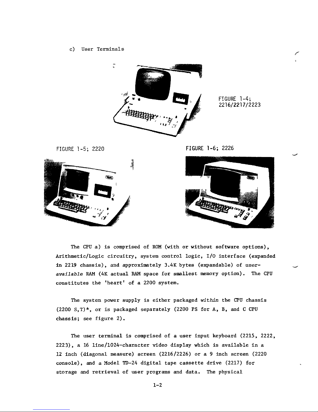
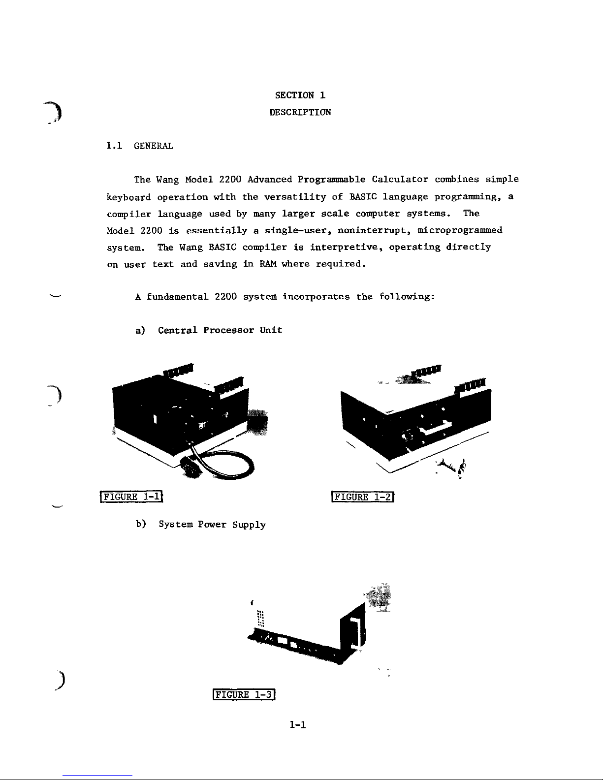
c)
User Terminals
FIGURE
1-4;
2216/2217/2223
FIGURE
1-5;
2220
FIGURE
1-6;
2226
The
CPU a) is
comprised
of ROM
(with
or
without software
options),
Arithmetic/Logic circuitry, system control logic,
I/O
interface (expanded
in
2219
chassis),
and
approximately 3.4K bytes
(expandable)
of
user-
available
RAM (4K
actual
RAM
space
for
smallest memory option)
. The CPU
constitutes
the
'heart'
of a
2200
system.
The
system power supply
is
either packaged within
the CPU
chassis
(2200
S,T)*,
or is
packaged separately
(2200
PS for A, B, and C CPU
chassis;
see
figure
2).
The
user terminal
is
comprised
of a
user input keyboard
(2215,
2222,
2223),
a 16
line/1024-character
video display which
is
available
in a
12
inch
(diagonal
measure) screen
(2216/2226)
or a 9
inch screen
(2220
console),
and a
Model
TD-24
digital
tape
cassette drive
(2217)
for
storage
and
retrieval
of
user programs
and
data.
The
physical
1-2
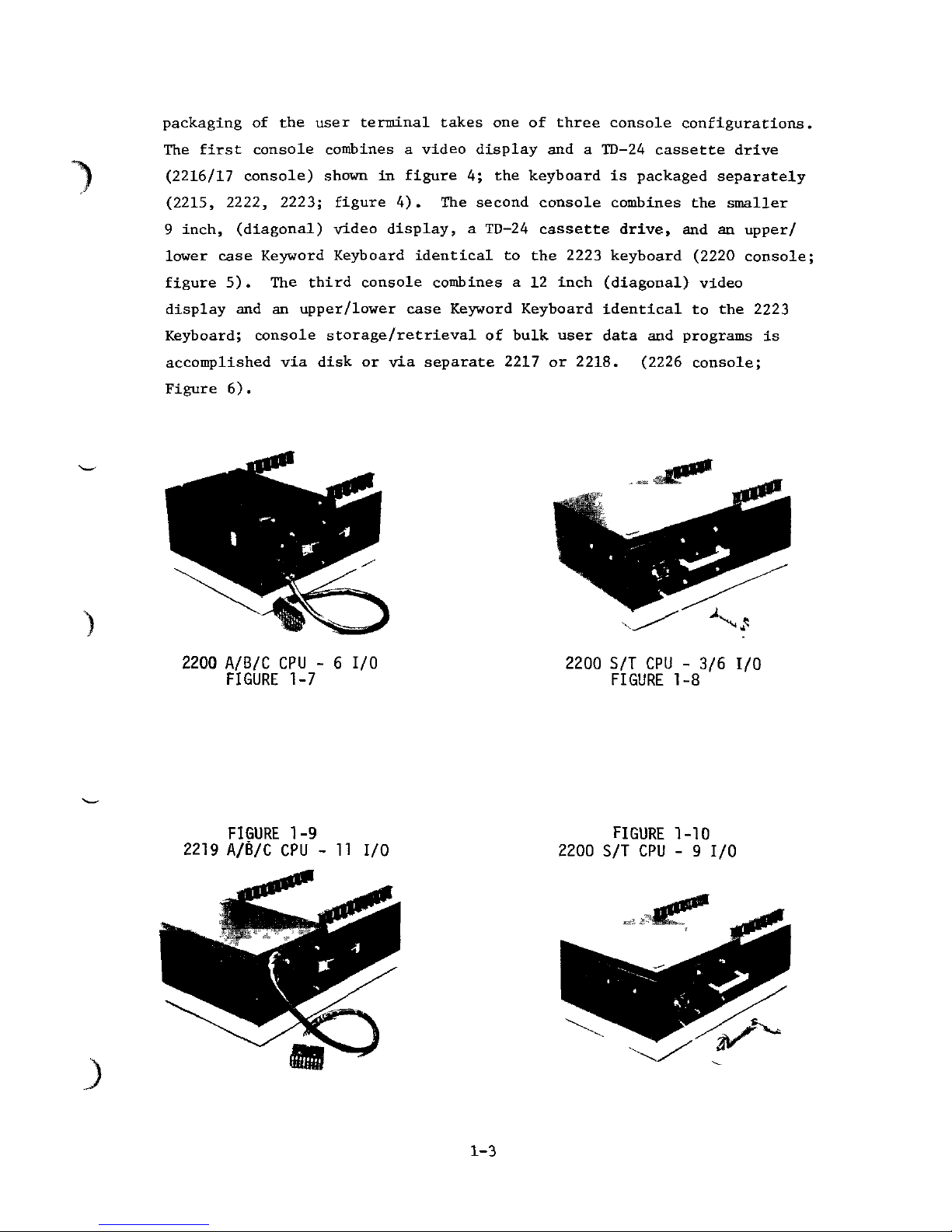
packaging
of the
user terminal takes
one of
three console configurations.
The
first console combines a video display
and a
TD-24
cassette drive
(2216/17
console)
shown
in
figure
4; the
keyboard
is
packaged separately
(2215,
2222, 2223; figure
4). The
second console combines
the
smaller
9
inch,
(diagonal)
video display, a TD-24
cassette drive,
and an
upper/
lower
case Keyword Keyboard identical
to the
2223 keyboard
(2220
console;
figure
5). The
third console combines
a 12
inch
(diagonal)
video
display
and an
upper/lower case Keyword Keyboard identical
to the
2223
Keyboard;
console storage/retrieval
of
bulk user data
and
programs
is
accomplished
via
disk
or via
separate 2217
or
2218.
(2226
console;
Figure
6).
2200 A/B/C
CPU - 6 I/O
FIGURE
1-7
2200
S/T CPU - 3/6 I/O
FIGURE
1-8
FIGURE
1-9
2219
A/B/C
CPU - 11 I/O
FIGURE
1-10
2200
S/T CPU - 9 I/O
1-3
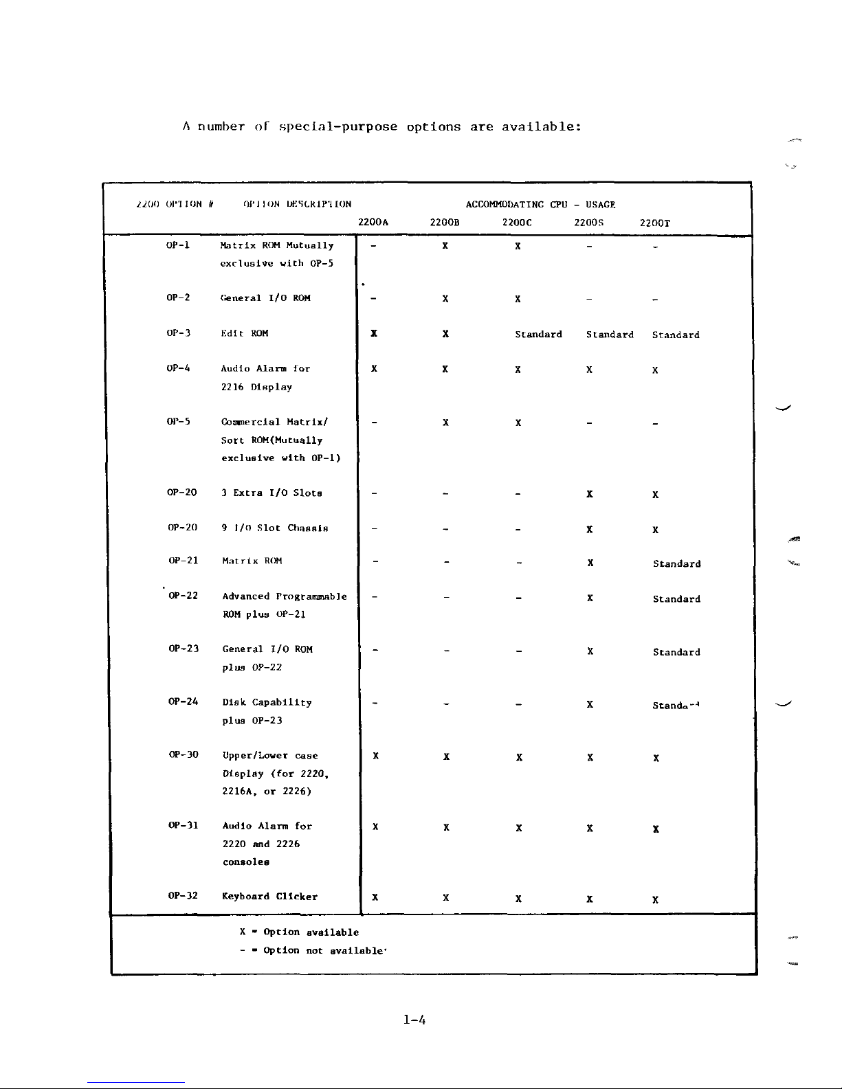
A
number
of
special-purpose options
are
available:
2200
OKI I ON It
01'J
I ON
DKSCKiniON
ACCOMMODATING
CPU -
USAGE
2200B
2200C
2200S 2200T
OP-l
OP-2
OP-
3
OP-4
OP- 5
OP-20
OP-
20
OP-
21
OP-22
OP-23
OP-24
OP-
30
OP-31
OP- 32
Matrix
ROM
Mutually
exclusive
with
OP-5
General
I/O
ROM
Kdlt
ROM
Audio
Alarm
for
2216
Dlnplay
Commercial
Matrix/
Sort
ROM(Mutually
exclusive
ulth
OP-l)
3
Extra
I/O
Slots
9 I/O
Slot
Ch.ieelB
Mntrlx
ROM
Advanced
Programmable
ROM
plus
OP-21
General
I/O
ROM
plus
OP-22
Disk
Capability
plus
OP-23
Upper/Lower
case
Display
(for 2220,
2216A,
or
2226)
Audio
Alarm
for
2220
and
2226
consoles
Keyboard
Clicker
- X X - -
- X X - -
X
X
Standard Standard Standard
X X X X X
- X X - -
X X
X X
- - X
Standard
- - - X
Standard
X
Standard
- - X
Stand.--
1
X
X X X X
X
X X X X
X
X X X X
X - Option
available
- -
Option
not
available'
1-4
Option
Descriptions
Options
1 or 21
(OP-I/
OP-21) provide matrix statements designed
\ to
reduce execution time
and use
less
RAM
than would
be
required using
standard
2200
statements
to
program matrix operations.
Options
2 or 23
(OP-2,
OP-23) allows
the
user
to
custom-tailor
input/output
operations
to
suit special peripheral devices. This option
also facilitates high-speed character code translation
and
data
packing/
unpacking.
Option 3 (OP-3)
allows individual alphanumeric characters
in a
line
of
program text, data values,
or
program
text
currently being
entered
from a Keyboard,
to be
altered, deleted,
or
inserted without
_,
inputting
the
entire program line
again.
Options
l* or 31
(OP-4,
OP31) cause
an
audible signal
to
alert
the
system user when (for example)
an
error occurs under program control.
The
alarm
may be
sounded
by
programming a predesignated
HEX
code wherever
desired.
Option 5 (OP-5)
provides
six
matrix statements
for
flexible
and
rapid
searching, moving,
and
ordering data
in
System
2200B
or C
CPU's.
Option
5 is
mutually exclusive with Option
1.
Options
20 and 20A
(OP-20,
OP-20A) provide 6-slot
and
9-slot
I/O
capabilities
(respectively) with
any
2200S
or
2200T
CPU.
Option
22
(OP-22)
provides eleven
bit and
byte
manipulation
statements
and
functions which greatly increase processing capability
by
reducing programming requirements
for
such applications. Option
22
includes Option
21.
Option
24
(OP-24)
provides
all
disk
I/O
capabilities,
and
includes
Options
22 and 21.
Option
32
(OP-52)
causes
an
audible
"click"
whenever
a key is
}
depressed; thus
an
experienced programmer
or
typist (for example) need
1-5
not
"bottom
out"
a key to
ensure entry, thereby increasing
input
speed.
The
"click" sound also lessens
the
need
to
verify entry
by
checking
the
video display.
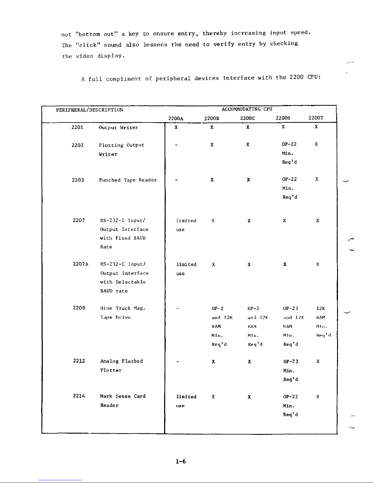
A
full
compliment
of
peripheral devices interface with
the
2200
CPU:
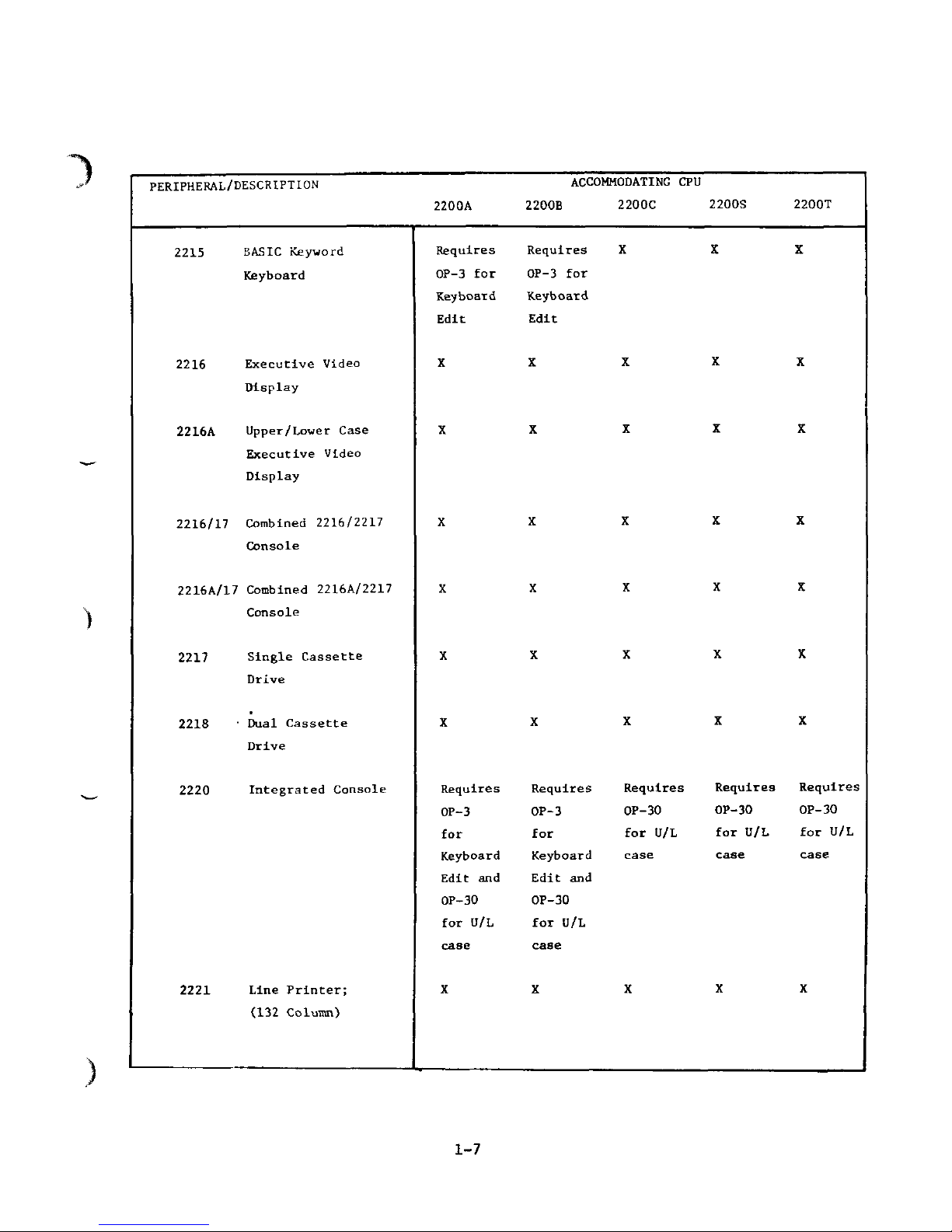
PERIPHERAL/DESCRIPTION
ACCOMMODATING
CPU
2200A
2200B
2200C
2200S
2200T
2201 Output Writer
2202
Plotting
Output
Writer
2203
Punched
Tape
Reader
2207
RS-232-C
Input/
Output
Interface
with
Fixed
BAUD
Rate
2207A
RS-232-C
Input/
Output
Interface
with
Selectable
BAUD
rate
2209
Nine
Track
Mag.
Trfpe
Drive
2212 Analog Flatbed
Plotter
2214
Mark
Sense
Card
Reader
X
X X X X
X
X
OP-22
X
Min.
Req'd
X
X
OP-22
X
Min.
Req'd
limited
X X X X
use
limited
X X X X
use
OP-2
OP-2
OP-23
12K
and 12K
dncl
1 ?K ,md WK KAM
HAM
KAM HAM
MI,,.
Mill.
Min. HIM.
KPI|"'
Req'd
Req'd
Req'd
- X X
OP-23
X
Min.
Req'd
limited
X X
OP-22
X
use
Min.
Req'd
1-6
PERIPHERAL/DESCRIPTION
2200A
2215
2216
2216A
2216/17
2216A/17
2217
2218
2220
2221
BASIC
Keyword
Keyboard
Executive
Video
Display
Upper/Lower
Case
Executive
Video
Display
Combined
2216/2217
Console
Combined
2216A/2217
Console
Single Cassette
Drive
Dual Cassette
Drive
Integrated
Console
Line Printer;
(132 Column)
Requires
OP-3
for
Keyboard
Edit
X
X
X
X
X
X
Requires
OP-3
for
Keyboard
Edit
and
OP-30
for
U/L
case
X
ACCOMMODATING
CPU
2200B
2200C 2200S 2200T
Requires
XXX
OP-3
for
Keyboard
Edit
X X X X
X
X X X
X X X X
X X X X
X X X X
X X X X
Requires
Requires Requires Requires
OP-3
OP-30 OP-30 OP-30
for
for U/L for U/L for U/L
Keyboard
case case case
Edit
and
OP-30
for U/L
case
X X X X
1-7
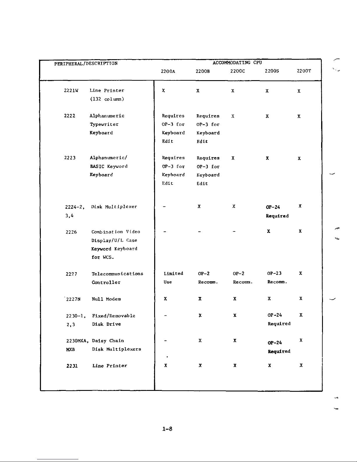
PERIPHERAL/DESCRIPTION
ACCOMMODATING
CPU
2200A
2200B 2200C 2200S 2200T
2221W
2222
2223
2224-2,
3,4
2226
2227
'2227N
2230-1,
2,3
2230MXA,
MXB
2231
Line
Printer
(132 column)
Typewriter
Keyboard
Alphanumeric/
BASIC
Keyword
Keyboard
Disk
Multiplexer
Combination
Vtdeo
Display/U/L
Case
Keyword Keyboard
for
WCS.
Telecommunications
Controller
Null
Modem
Fixed
/Re
movable
Disk
Drive
Daisy Chain
Disk
Multiplexers
Line
Printer
X X X X X
OP-3
for
OP-3
for
Keyboard
Keyboard
Edit
Edit
Requires
Requires
XXX
OP-3
for
OP-3
for
Keyboard Keyboard
Edit
Edit
X
X
QP-24
*
Required
- - - X X
Limited
OP-2 OP-2
OP-23
X
Use
Recomm. Recomm. Recotmn.
X X X X X
- X X
OP-24
X
Required
X X
OP-24
X
Required
X
X X X X
1-8
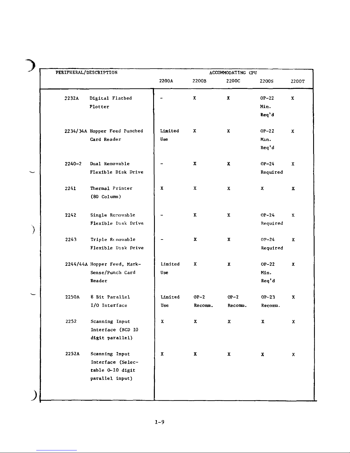
PERIPHERAL/DESCRIPTION
ACCOMMODATING
CPU
2200A
2200B
2200C
2200S
2232A
Digital
Flatbed
Plotter
2234/34A
Hopper Feed Punched
Card Reader
2240-2
Dual
Removable
Flexible Disk Drive
2241
Thermal
Printer
(80
Column)
2242
Single
Rcnovable
Flexible Disk Drive
2243
Triple
Removable
Flexible Disk Drive
2244/44A
Hopper Feed, Mark-
Sense/Punch
Card
Reader
2250A
8 Bit
Parallel
I/O
Interface
2252
Scanning
Input
Interface (BCD
10
digit
parallel)
2252A
Scanning
Input
Interface
(Selec-
table 0-10 digit
parallel
input)
- X X
OP-22
Min.
Req'd
Limited
X X
OP-22
Use
Min.
Req'd
- X X
OP-24
Required
X X X X
- X X
OP-24
Required
- X X
OP-24
Required
Limited
X X
OP-22
Use
Min.
Req'd
Limited
OP-2 OP-2
OP-23
Use
Recomm.
Recomm. Recomm.
X
X X X
X
X X X
2200T
X
X
X
X
X
X
X
X
X
X
1-9
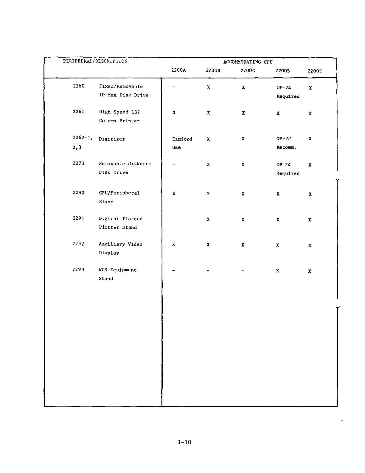
PERIPHERAL/DESCRIPTION
ACCOMMODATING
CPU
2200A
2200B
2200C
2200S
2200T
2260
Fixed/Removable
10 Meg
Disk
Drive
2261 High Speed
132
Column Printer
2262-1,
Digitizer
2,3
2270
Removible Diskette
Disk
Drive
2290
CPU/Peripheral
Stand
2291 Digital Flatoed
Plotter
Stand
2292
Auxiliary Video
Display
2293
WCS
Equipment
Stand
-XX
OP-24
X
Required
X X X X X
Limited
X X
OP-22
X
Use
Recomm.
- X X
OP-24
X
Required
X
X X X X
X X X X
X X X X X
X X
1-10
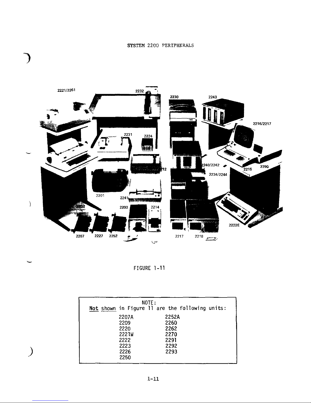
SYSTEM
2200
PERIPHERALS
*a^"P"~^^"
f^/rn
a
*^-=fgjk
2207
2227 2252
2217
221
FIGURE
1-11
Not
shown
NOTE
in
Figure
11
2207A
2209
2220
2221W
2222
2223
2226
2250
are the
following
2252A
2260
2262
2270
2291
2292
2293
units:
PERIPHERAL
DESCRIPTIONS
The
Model
2201
Output
Writer
types
numeric
and
upper
and
lower
case alphabetic output from
the
System
2200
with full format
control.
In the
Model
2202
Plotting
Output
Writer,
complete digital plotting
is
combined with
the
alphanumeric capability
of the
Model 2201. Thus,
plots
are
easily titled
and
labeled. (Both
the
Model 2201
and the
Model
2202
can be
used
as
standard electric typewriters
when
not
being used
with
the
System
2200.)
With
the
Model
2203
Punched
Tape
Reader,
paper tape
data
in
any
code
format
is
automatically
read
to the
system,
providing
an
efficient "data reduction" system.
The
reader supports,
5, 6, 7 or
8
track paper tape.
The
Model
2207
RS-232-C
I/O
Interface
Controller
is an
earlier
version
of the
2207A,
and
operates
at a
fixed baud rate.
The
Model
2207A
RS-232-C
I/O
Interface
Controller
allows attachment
TJ
of a Model
33
Teletype
as a
terminal
for the
system, generating hardcopy
and
inputting
programs
and
data stored
on
Teletype-punched
paper tape
or
issued from
the
keyboard.
It
also
supports interfacing
of
other Teletype-
compatible
instrumentation
or
terminals
at
110, 150, 300,
600 or
1,200 baud.
The
Model
2209
Nine-Track
Magnetic
Tape
Drive
provides
the
capability
to
store programs
and
data
on
half-inch
IBM
compatible
tapes.
A ten
inch diameter reel
can
accommodate
up to 20
megabytes
of
information.
The
Model
2212
Analog
Flatbed
Plotter
(10" x 15") provides
continuous line
or
point plotting
of
curves
and
data,
as
well
as
full alphanumeric labeling
of
plots with
the
System
2200.
With
the
Model 2214
Mark
sense
Card
Reader,
data
and
programs
can
be
entered directly into
the
system
via
optical mark sense cards.
With
this
low
cost reader cards
can be
prepared
"off-line"
without
tying
up the
keyboard (making
the
system more
efficient)
and are
manually
fed
into
the
Model 2214.
1-12
The
Model
2215
BASIC
Keyword
Keyboard
contains single keys
for
most BASIC language verbs
and
commands.
The
keyboard also contains
all
alphabetic characters
as
well
as all
program execution keys
needed
to
run
the
System
2200.
The
Model
2216
Executive
Video
Display
provides sixteen lines
of
64
characters each, displayed
on a 12"
(diag. meas.)
CRT
screen.
The
Model
2216A
Upper
and
Lower
Case
Video
Display
provides
16
lines
of 64
characters each,
in
either upper
or
lower case alphanumeric
characters.
The
Model
2217
Single
Tape
Cassette
Drive
provides a bulk
storage
system
for
both programs
and
data. A 150-foot
tape
has a
capacity
of
78,000
(8-bit)
bytes, with
an
input/output transfer rate
of 326
bytes
per
second.
The
Model
2216/2217
Combined
CRT
Executive
Display/Single
Tape
Cassette
Drive
Console
is a
video display
and
tape drive contained
in
the
same
chassis.
The
Model
2216A/2217
combined
Upper
and
Lower
Case
CRT/Single
Tape
Drive
contains a video display
and a
tape drive
in one
chassis.
The
display
I/O
controller provides upper/lower case character output
to
the
display
(2216A).
The
Model
2218
Dual
Tape
Cassette
Drive
consists
of two
tape
drives contained
in a
single unit.
The
tape drives
are
identical
in
operation
and
performance
to the
Model 2217.
One CPU I/O
Controller
operates both tape drives,
but
each
tape
drive operates independently,
with
separate
device
addresses.
The
Model
2219
Extended
I/O
Chassis
is a
2200
A, B, or C CPU
option which provides
an
additional five
I/O
slots (for a total
capacity
of 11
peripheral
devices).
1-13
The
Model
2220
Console
contains
a 9
inch video display, a cassette
drive,
and an
upper/lowercase Keyword Keyboard.
The
2220
is a
self
contained
user terminal
and can be
used
in
conjunction with a 2200A.
B, C, S, or T
CPU.
On the
Model
2221
Line
Printer
(132
column),
hardcopy output
is
printed
at 150
characters
per
second
or 60 to 200
lines
per
minute,
depending
upon
line
length.
The
2221W
Dot
Matrix
Impact
Printer
(132-column) , hardcopy output
is
200
characters
per
second
and
65-300
lines
per
minute, depending
on
line
length.
The
Model
2222
Alpha-Numeric
Typewriter
Keyboard
enables
the
user
to
input
upper
and
lower case alphanumeric characters
and
program control
and
execution keys
from a keyboard similar
to a
standard typewriter
Keyboard.
The
2223
Alphanumeric
BASIC
Keyword
Keyboard
enables
the
user
to
input either upper/lowercase characters
or
most BASIC Programming
words with a single keystroke;
an
edit
feature (std. with
C, S and T
CPU's)
allows efficient
program
editting.
The
Model
2224
Disk
Multiplexer
allows
the use of
four System
2200
Central Processing Units with a single disk unit remotely located
up
to
500' (152
m.)
from each CPU,
to
maximize
use of the
disk unit.
The
2226
combines
a 12"
video
display
and an
upper/lowercase
Keyword Keyboard into
one
console
chassis.
The
Model
2227
Telecommunications
Controller
allows
local
or
remote
asynchronous communication between System
2200's
or
remote
telecommunications with
"foreign"
CPUs (IBM, Univac,
Honeywell,
et
cetera).
Model
2200
software enables
the
system
to
become
an
"intelligent
terminal"
with
the
Model 2227.
The
Model
2228
Binary
Synchronous
Telecommunications
Controller,
when accompanied
by a
suitable modem (modulator/demodulator),
and the
terminal emulator program, a System
2200
or a
Wang Computer System
can
transmit
and
receive data over dial-up communications lines
linking
the
1-14
system
to
another comparably
equipped
Wang system
or to any
mainframe
computer
which
can
communicate with
a IBM
2780
terminal.
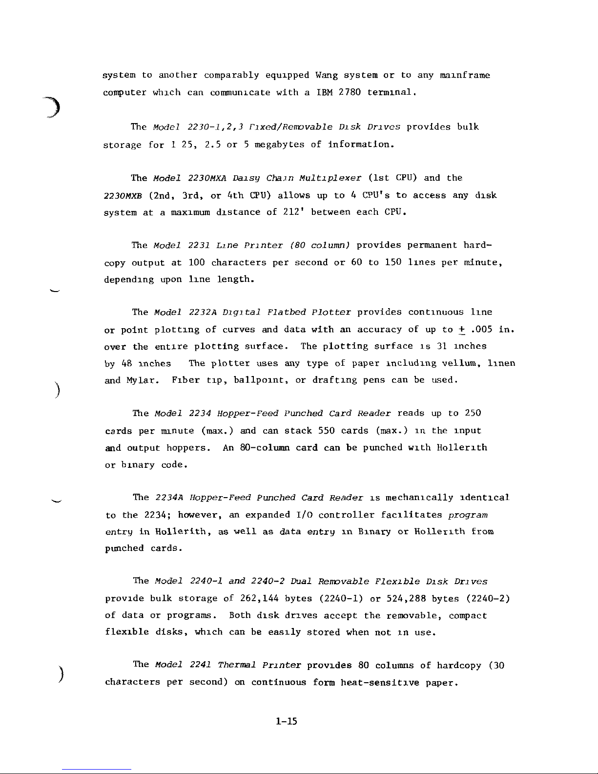
The
Model
2230-1,2,3
Fixed/Removable
Disk
Drives
provides bulk
storage
for 1 25, 2.5 or 5
megabytes
of
information.
The
Model
2230MXA
Daisy
Chain
Multiplexer (1st CPU)
and the
2230MXB
(2nd, 3rd,
or 4th
CPU)
allows
up to 4
CPU's
to
access
any
disk
system
at a
maximum distance
of
212* between each CPU.
The
Model
2231
Line
Printer
(80
column) provides permanent hard-
copy
output
at 100
characters
per
second
or 60 to 150
lines
per
minute,
depending
upon line length.
The
Model
2232A
Digital
Flatbed
Plotter
provides continuous line
or
point plotting
of
curves
and
data with
an
accuracy
of up to +
.005
in.
over
the
entire plotting surface.
The
plotting surface
is 31
inches
by
48
inches
The
plotter
uses
any
type
of
paper
including
vellum,
linen
and
Mylar. Fiber tip, ballpoint,
or
drafting pens
can be
used.
The
Model
2234
Hopper-Feed
Punched
Card
Reader
reads
up to 250
cards
per
minute
(max.)
and can
stack
550
cards
(max.)
in the
input
and
output hoppers.
An
80-column
card
can be
punched with Hollerith
or
binary code.
The
2234A
Hopper-Feed
Punched
Card
Reader
is
mechanically identical
to
the
2234; however,
an
expanded
I/O
controller facilitates program
entry
in
Hollerith,
as
well
as
data
entry
in
Binary
or
Hollerith
from
punched cards.
The
Model
2240-1
and
2240-2
Dual
Removable
Flexible
Disk
Drives
provide
bulk storage
of
262,144
bytes
(2240-1)
or
524,288
bytes
(2240-2)
of
data
or
programs. Both disk drives accept
the
removable, compact
flexible disks, which
can be
easily stored
when
not in
use.
The
Model
2241
Thermal
Printer
provides
80
columns
of
hardcopy
(30
characters
per
second)
on
continuous form
heat-sensitive
paper.
1-15
The
Model
2242
single
Removable
Flexible
Disk
Drive
is
similar
to
the
Model
2240,
but
contains
one
flexible disk drive
and
provides storage
for
262,144
bytes
of
information.
The
Model
2243
Triple
Removable
Flexible
Disk
Drive
contains
three
flexible disk drives,
and
provides storage
for a
total
of
786,432
bytes.
The
removable, compact platters (used
in the
Model
2240,
2242,
and
2243)
are
interchangeable between
the
three disk drives
of the
unit
and
any
other
2240
series disk system.
The
Model
2244
Hopper-Feed
Mark
Sense/Punched
Card
Reader
reads
up to 250
cards
per
minute
and can
stack
550
cards
in the
input
or
output hoppers.
The
Model 2244 reads standard 80-column punch cards
(the same card used with
the
Model
2234);
80-column optical mark
sense
cards
without
clock
marks
(either punched
or
marked
in
pencil);
and
optical mark
sense
cards
with
timing
marks
and 80
columns
or
less
of
data
(punched
or
marked).
Data entry
can be in
Hollerith
or
binary
code.
The
2244A
Hopper-Feed
Mark
Sense/Punched-Card
Reader
is
mechanically
identical
to the
2244; however,
an
expanded
I/O
controller facilitates
program
entry
in
Hollerith, Standard Educational Format
and
Wang Format,
as
well
as
data
entry
in
Binary
or
Hollerith.
The
Model
2250A
I/O
Interface
Controller
(8-Bit-Parallel)
enables
interfacing
of
8-bit parallel
I/O
devices. Parallel 8-bit data
can be
transmitted
or
received
by a
2250A/2200
system.
The
Model
2252
Input
Interface
Controller
(BCD
10-Digit-
Parallel),
an
input-only interface,
is
directly compatible
to
most
digital meters
for
on-line applications.
It
automatically converts
each
BCD
digit
to an
ASCII equivalent code. Optionally,
it
also
can
be
used
to
receive
up to 40
discrete bits
of
parallel binary data.
The
Model
2252A
is a
later version
of the
2252,
and
allows manual
selection
of 1 to 10
parallel
BCD
digits
to be
input
to the
2200
CPU.
Groups
of 4
discrete binary
bits
each
may be
entered
by the
same select
feature.
Generally speaking, selection
of
less than
10
digits input
allows faster input processing cycles.
1-16
3
The
Model
2260
Fixed/Removable
Disk
Drive
provides
ten
megabytes
(10,027,008
total
bytes)
of
on-line
storage.
The
unit's
total
storage
capacity
is
divided equally between
two
separate
hard-disk
platters,
one of
which
is
removable
and can be
conveniently
stored.
The
Model
2261
High-Speed Printer utilizes
two
bidirectional
printing heads
to
print
up to 330
characters
per
second,
or 125
lines
per
minute
(132
characters
per
line,
maximum).
The
Model
2262
XY
Digitizer
provides
the
capability
to
digitize
single
points
or
curves
on a
Cartesian
plane
at a
resolution
of +
.005
inches over
the
entire digitizing
surface.
The
Model
2270
Shugart
Floppy
Disk Chassis
is
available
in
three
models
(-1,
-2, and -3)
containing
one to
three
flexible
disk
drives.
This unit
is an
integral part
of
each
WCS
(Wang
Computer System; models
-20 and
-30).
The
Model 2290 CPU/Peripheral Stand stores
fhe
System
2200
CPU
(either
the
standard
CPU,
S/T
CPU's,
9-slot
S/T
CPU's
or the
Model
2219
Extended
I/O
Chassis)
and the
Power
Supply.
The
stand Includes
four
electrical outlets
and a
master ON/OFF switch located
on the
front.
The
table
top can
accommodate a user terminal,
or
other
peripheral
devLcc.
The
Model 2291
Flatbed
Plotter/Peripheral
Stand
provides a sturdy
surface
for the
Model 2232A Flatbed Plotter.
The
2292
Auxllliary
Video
Display
is a 12" CRT
display
unit
used
in
conjunction
with standard display capabilities
of the
2200
system.
The
2292
can
display
the
same
information
as is
presented
on a
2216
or
2220
console display.
Up to
twelve
2292's
may be
cascaded.
The
2293
WCS
Equipment
Stand
accommodates a 2200
S or T
CPU,
a
2270
Shugart
disk
drive
(up to 3
drives),
and a
user
Input/Output
console.
It
is
standard with Wang Computer Systems
(HCS)
-20 and
-30.
1-17
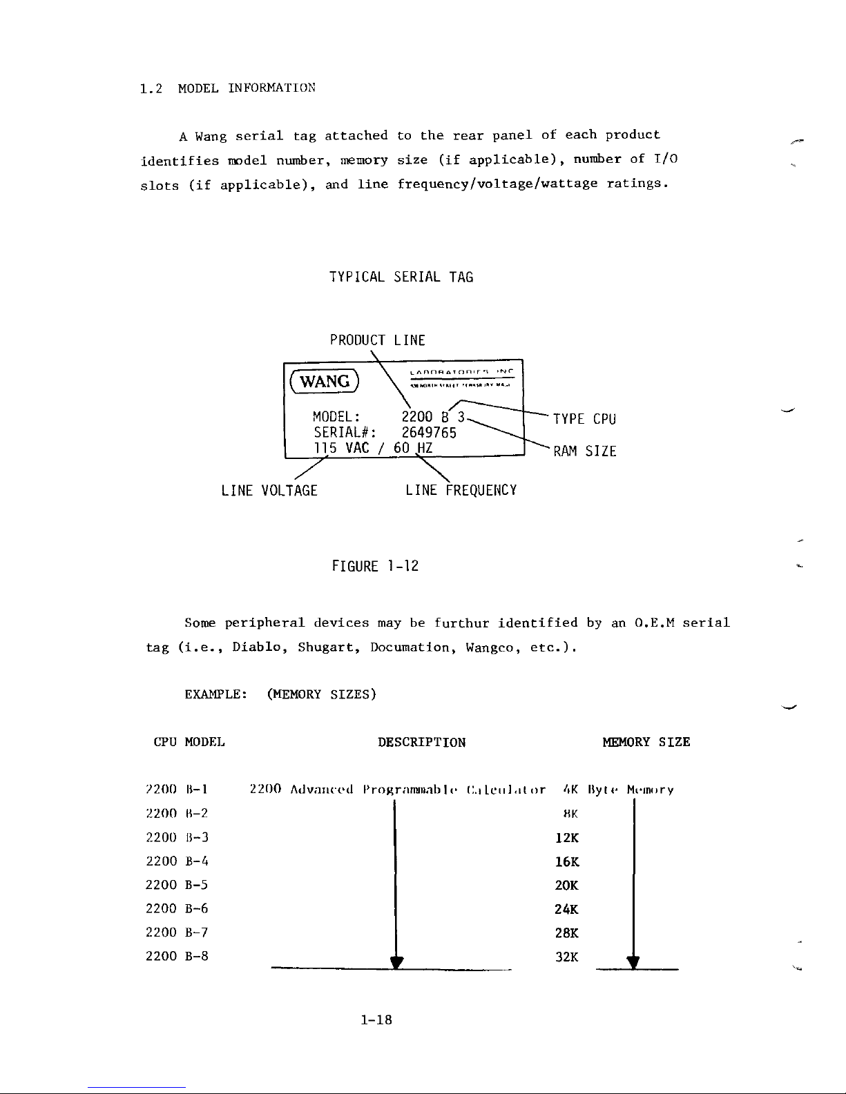
1.2
MODEL INFORMATION
A
Wang serial
tag
attached
to the
rear panel
of
each
product
identifies model number, memory size
(if
applicable), number
of I/O
slots
(if
applicable),
and
line frequency/voltage/wattage ratings.
TYPICAL SERIAL
TAG
PRODUCT
LINE
\
MODEL:
2200
B
SERIAL*:
2649765
115
VAC / 60 HZ
LINE
VOLTAGE
LINE
FREQUENCY
FIGURE
1-12
Some
peripheral devices
may be
furthur
identified
by an
O.E.M serial
tag
(i.e.,
Diablo, Shugart, Documation, Wangco, etc.).
EXAMPLE:
(MEMORY
SIZES)
CPU
MODEL
DESCRIPTION
MEMORY SIZE
2200
lt-1
2200
Advanced Programmable
C.i
leu]
,il
or 4K
Kyle
Memory
2200
11-2
UK
2200
B-3 12K
2200
B-4 16K
2200
B-5 20K
2200
B-6 24K
2200
B-7 28K
2200
B-8 . . 32K
1-18
 Loading...