

Page 1

Wandy 2R client Manual
The Wandy unit is an “Active WiFi outdoor antenna”. The unit consist of an antenna with high gain and a WiFiEthernet-client. The slim line enclosure is compact and made of all weather ABS for years of uninterruptible
operation. Long distance connections are easy with the Wandy 2R. Simple installation with Power Over Ethernet.
Build in router function provides extra security for internet connections. Wandy 2R for fast, stable and long range
WiFi connections.
Version 0.91
Page 2

Table of Contents
1 Preface ..................................................................................................................................................................4
2 Packing List ...........................................................................................................................................................5
3 Configuration Wandy 2R .......................................................................................................................................6
4 Concept of the Wandy radio hardware................................................................................................................12
4.1 Wireless Interface ..........................................................................................................................................12
4.2 Wireless to Wired connection........................................................................................................................12
5 Wireless...............................................................................................................................................................14
5.1 Basic settings.................................................................................................................................................14
5.2 Advanced settings .........................................................................................................................................15
5.3 Security..........................................................................................................................................................17
5.3.1 WEP Encryption Setting........................................................................................................................18
5.3.2 64-bit WEP Encryption..........................................................................................................................18
5.3.3 128-bit WEP Encryption........................................................................................................................19
5.3.4 WEP Encryption with 802.1x Setting ....................................................................................................19
5.3.5 WPA Encryption Setting........................................................................................................................19
5.3.6 WPA Authentication Mode....................................................................................................................19
5.4 Access Control...............................................................................................................................................19
5.5 Configuring WDS ...........................................................................................................................................20
5.6 WDS network topology..................................................................................................................................21
5.6.1 Bus topology .........................................................................................................................................21
5.6.2 Star topology.........................................................................................................................................22
5.6.3 Ring Topology.......................................................................................................................................22
5.6.4 Mesh topology.......................................................................................................................................23
5.7 WDS Application............................................................................................................................................23
5.7.1 Wireless Repeater.................................................................................................................................23
5.7.2 Wireless Bridge.....................................................................................................................................24
5.8 Site Survey.....................................................................................................................................................24
5.9 Antenna Aligment ..........................................................................................................................................24
6 TCP/IP.................................................................................................................................................................26
6.1 Configuring LAN Interface.............................................................................................................................26
6.1.1 DHCP disabled......................................................................................................................................26
6.1.2 DHCP Client..........................................................................................................................................26
6.1.3 DHCP Server ........................................................................................................................................26
6.2 Configuring WAN Interface............................................................................................................................27
6.2.1 Static IP.................................................................................................................................................27
6.2.2 DHCP Client (Dynamic IP)....................................................................................................................28
6.2.3 PPPoE...................................................................................................................................................29
6.2.4 PPTP.....................................................................................................................................................30
7 Firewall ................................................................................................................................................................32
7.1 Port Filtering...................................................................................................................................................32
7.2 IP Filtering......................................................................................................................................................32
7.3 MAC Filtering.................................................................................................................................................33
7.4 Port Forwarding (Virtual Server)....................................................................................................................33
7.5 DMZ ...............................................................................................................................................................34
8 Management........................................................................................................................................................35
8.1 Wizard............................................................................................................................................................35
8.2 Operation Mode.............................................................................................................................................35
8.2.1 Router ...................................................................................................................................................36
8.2.2 Bridge....................................................................................................................................................36
8.2.3 WISP (Wireless ISP).............................................................................................................................36
8.3 Bandwidth Control .........................................................................................................................................37
8.4 Statistics.........................................................................................................................................................37
8.5 Dynamic DNS Setting....................................................................................................................................37
8.6 Time Zone......................................................................................................................................................38
8.7 Log.................................................................................................................................................................38
8.8 Upgrade Firmware.........................................................................................................................................39
8.9 Save/Reload Settings ....................................................................................................................................39
8.10 Password...................................................................................................................................................40
8.11 Reboot.......................................................................................................................................................40
Page 3

9 SSH login.............................................................................................................................................................42
Page 4

1 Preface
Thank you very much for buying the Wandy 2R unit. With this unit you do have a powerful combination of
electronics and antenna technology. Long distance outdoor WiFi connections are easily made by the simple
installation. Optimal performance is possible by free line of signed between the Wandy2R and the access point.
The setup procedure is
Connect the power to the Wandy2R unit Connect the PC to the Wandy 2R unit
Configure the Wandy2R for wireless network Install Wandy2R outdoor
Enjoy years of uninterruptible use of the Wandy2R
Connect the power to the Wandy 2R unit
Connect the PC to the Wandy 2R unit
Configure Wandy 2R for wireless network
Install Wandy 2R outdoor
Enjoy the years of uninterruptible use of the Wandy 2R
Page 5

2 Packing List
Before you start to install the Wandy 2R, make sure the package contains the following items
This package contains Manual Quick start
Wandy2R unit Power adapter
Wall mount
plugs
Mounting bracket Power cable
Wall mount
screws
1M cross cable
Pole mount
hardware
Mounting
bracket bolts
POE inserter unit Inbus tool
If anything is missing contact your supplier of the Wandy 2R
Page 6

3 Configuration Wandy 2R
Before installing the Wandy 2R unit outside it is best to configure first the unit indoor.
Connect the power supply to
the POE inserter unit.
P+DATA
OUT
DATA
IN
POWER IN
+ -
A
Connect the Wandy 2R unit to
the POE inserter unit. Wait one
minute to let the unit boot.
P+DATA
OUT
DATA
IN
POWER IN
+ -
!
For the wandy unit use the
P+DATA OUT port!
B
Connect the PC to the POE
inserter unit.
P+DAT
A
OUT
DAT
A
I
N
POWER
I
N
+
-
!
Connect your computer to the
DATA IN port!
damage your hardware!
D
Configure the wandy unit by
the web interface
Hi Wandy,
How are you?
Fine, thanks!
192.168.1.2
192.168.1.1
Username: root
Password: wandy
Enter Wandy's
configuration
page.
F
3.1 Wandy 2R in WISP mode
In this setup we will configure the default Wandy 2R unit to connect to an AP with SSID gamma1 and use the build
in router function.
The default config of the Wandy 2R unit is WISP mode. The wireless interface is in WiFi client mode and
connected to the Ethernet interface trough a router.
The default IP number if the Ethernet interface is 192.168.1.1
Page 7

Open the web interface of the Wandy 2R unit at IP 192.168.1.1
Select in the menu Wireless the option site survey
Press refresh to let the Wandy 2R unit make site survey
Page 8

We connect to the wireless network with SSID gamma1 by selecting this network and pressing connect.
We now configure the Wandy 2R unit to get an IP address from the AP.
Open the menu TCP/IP and then WAN interface
Page 9

Change WAN access Type to DHCP client to get an IP address form the AP to the Wandy 2R. Set the Attain DNS
Automatically. This will set automatically the DNS servers from the AP.
Press Apply Changes to make the setting effective
Click on status to see the current status of the unit
Page 10

In the status screen we can see that the unit is connected to AP with SSID gamma1
The Wireless interface (WAN) does have IP number 192.168.16.105 with gateway 192.168.16.2
The LAN interface does have IP number 192.168.1.1 with a DHCP server enabled.
Signal strength is -76 dBm.
The Wandy 2R is connected to an access point and has a router between the wireless interface and the wired.
On the PC set the gateway to the wandy 2R unit 192.168.1.1 to complete the setup.
Page 11

3.2 Wandy 2R in Bridge mode
In this setup we will configure the default Wandy 2R unit to connect to an AP with SSID gamma1 and make a
transparent connection between the wireless interface and wired.
Open the web interface of the Wandy 2R unit at IP 192.168.1.1
First change the operation mode of the Wandy 2R into bridge mode
Select in management Operation Mode
Page 12

4 Concept of the Wandy 2R radio hardware
The Wandy 2R has two interfaces
Wireless interface
Wired interface
These two interfaces are connected together with or without a router between them.
In bridge mode the wireless and Ethernet are directly connected. No routing or translating is done. In this mode the
unit can be used as a transparent device. The Wandy 2R can be even in different IP range.
4.1 Wireless Interface
The wireless radio of the device can acts as the following roles.
AP (Access Point)
The wireless radio of device serves as communications “hub” for wireless clients and provides a connection to a
wired LAN.
AP Client
This mode provides the capability to connect with the other AP using infrastructure/Ad-hoc networking types. With
bridge operation mode, you can directly connect the wired Ethernet port to your PC and the device becomes a
wireless adapter. And with WISP operation mode, you can connect the wired Ethernet port to a hub/switch and all
the PCs connecting with hub/switch can share the same public IP address from your ISP.
WDS (Wireless Distribution System)
This mode serves as a wireless repeater, the device forwards the packets to another AP with WDS function. When
this mode is selected, all the wireless clients can’ survey and connect to the device. The device only allows the
WDS connection.
WDS+AP
This mode combines WDS plus AP modes, it not only allows WDS connections but also the wireless clients can
survey and connect to the device.
4.2 Wireless to Wired connection
The Wireless and Wired interface can be connected together with or without a router function.
Router
The wired Ethernet (WAN) port is used to connect with ADSL/Cable modem and the wireless NIC is used for your
private WLAN. The NAT is existed between the 2 NIC and all the wireless clients share the same public IP address
through the WAN port to ISP. The default IP configuration for WAN port is static IP. You can access the web server
of device through the default WAN IP address 172.1.1.1 and modify the setting base on your ISP requirement.
Bridge
The wired Ethernet and wireless NIC are bridged together. Once the mode is selected, all the WAN related
functions will be disabled.
WISP (Wireless ISP)
This mode can let you access the AP of your wireless ISP and share the same public IP address form your ISP to
the PCs connecting with the wired Ethernet port of the device. To use this mode, first you must set the wireless
radio to be client mode and connect to the AP of your ISP then you can configure the WAN IP configuration to meet
your ISP requirement.
The following table shows the supporting combination of operation and wireless radio modes.
Bridge Router WISP
AP Yes Yes No
Page 13

WDS Yes Yes No
Client Yes No Yes
AP+WDS Yes Yes No
Page 14
5 Wireless
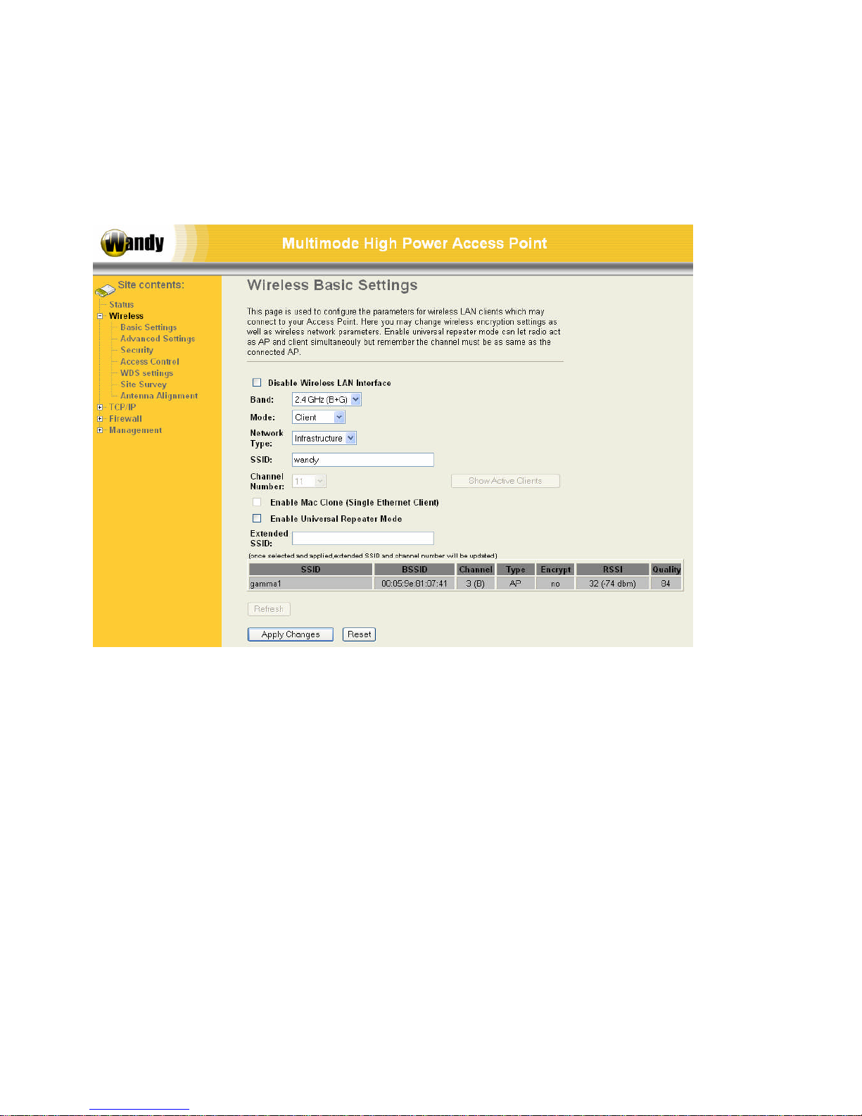
In this menu it will be possible to configure the device for all the wireless settings. To change to operation mode go
the menu Management.
5.1 Basic settings
Disable Wireless LAN Interface
Disable the wireless interface of device
Band
The device supports 2.4GHz(B), 2.4GHz(G) and 2.4GHz(B+G) mixed modes. Mode:
The radio of device supports different modes as following:
Mode:
AP
The radio of device acts as an Access Point to serves all wireless clients to join a wireless local network.
Client
Support Infrastructure and Ad-hoc network types to act as a wireless adapter.
WDS
Wireless Distribution System, this mode serves as a wireless repeater, only devices with WDS function
supported can connect to it, all the wireless clients can’t survey and connect the device when the mode is
selected.
AP+WDS
Support both AP and WDS functions, the wireless clients and devices with WDS function supported can
survey and connect to it.
Network type:
Page 15
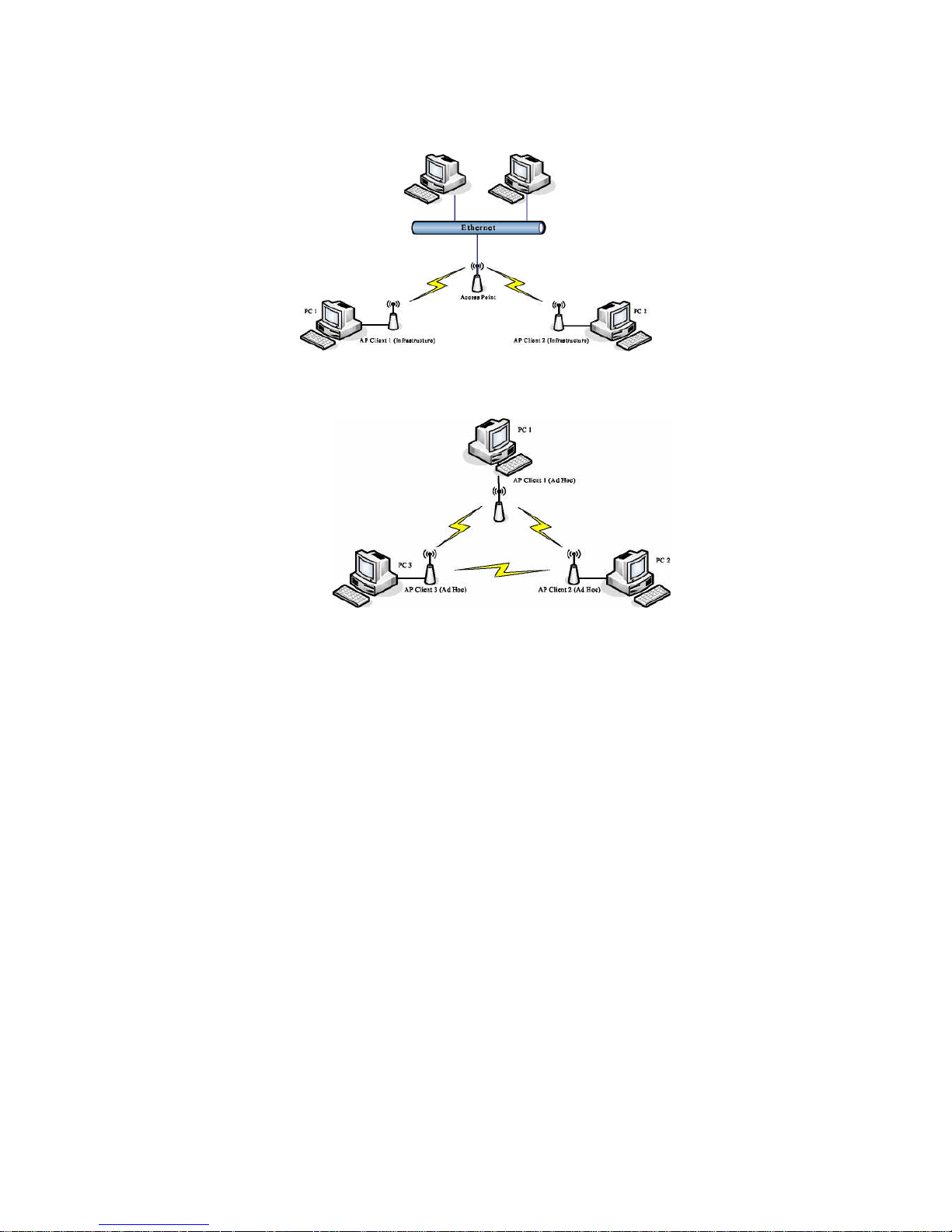
Infrastructure:
This type requires the presence of 802.11b/g Access Point. All communication is done via the Access
Point.
Ad Hoc:
This type provides a peer-to-peer communication between wireless stations. All the communication is done
from Client to Client without any Access Point involved. Ad Hoc networking must use the same SSID and
channel for establishing the wireless connection.
Channel Number
The channel the unit will operate on. When set to “Auto”, the device will find the least-congested channel for use.
Enable Mac Clone (Single Ethernet Client)
The MAC address of the unit will be the MAC address of the PC connected to the Wandy 2R unit. This canb only
be done in Client mode.
Enable Universal Repeater Mode
Universal repeater mode will make the Wandy 2R unit become client as well as AP on the same radio. In this mode
it can repeater any vendor AP.
Extended SSID:
The SSID of the Universal repeater mode can be different from the AP the client is connected to.
5.2 Advanced settings
These settings are only for more technically advanced users who have sufficient knowledge about wireless LAN.
These settings should not be changed unless you know what effect the changes will have on your device. The
default setting is optimized for the normal operation. For specific application, setting configuration will required
highly attention to reach optimistic condition.
Any unreasonable value change to default setting will reduce the throughput of the device.
Page 16
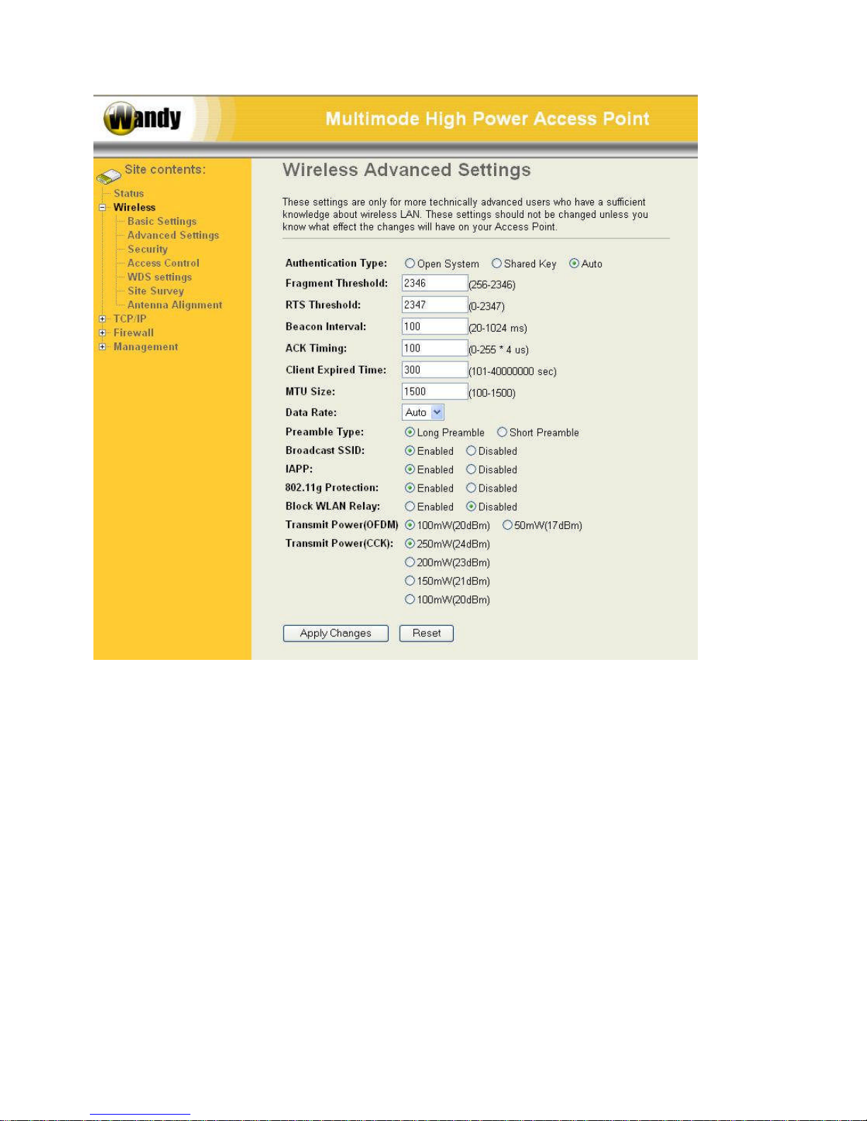
Authentication Type
The device supports two Authentication Types “Open system” and “Shared Key”. When you select “Share Key”,
you need to setup “WEP” key in “Security” page (See the next section). The default setting is “Auto”. The wireless
client can associate with the device by using one of the two types.
Fragment Threshold
The fragmentation threshold determines the size at which packets are fragmented (sent as several pieces instead
of as one block). Use a low setting in areas where communication is poor or where there is a great deal of radio
interference. This function will help you to improve the network performance.
RTS Threshold
The RTS threshold determines the packet size at which the radio issues request to send (RTS) before sending the
packet. A low RTS Threshold setting can be useful in areas where many client devices are associating with the
device, or in areas where the clients are far apart and can detect only the device and not each other. You can enter
a setting ranging from 0 to 2347 bytes.
ACK timing.
For long distance 802.11G it will be necessary to increase the ACK timing value. When operating at
802.11B the ACK timing value needs to be at least 100. For short distance 802.11G the value can be less.
Data Rate
The standard IEEE 802.11b/11g supports 1, 2, 5.5,11/6, 9, 12, 18, 24, 36, 48 and 56 Mbps data rates. You can
Page 17
choose the rate that the device uses for data transmission. The default value is “auto”. The device will use the
highest possible selected transmission rate.
Beacon Interval
The beacon interval is the amount of time between access point beacons in microseconds. The default beacon
interval is 100.
Broadcast SSID
Broadcasting the SSID will let your wireless clients find the device automatically. If you are building a public
Wireless Network, disable this function can provide better security. Every wireless stations located within the
coverage of the device must connect this device by manually configure the SSID in your client settings.
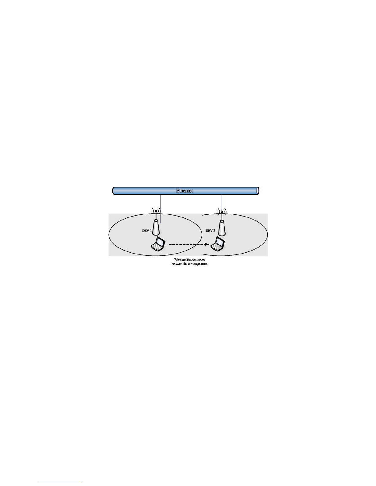
Int. Roaming
This function will let Wireless Stations roam among a network environment with multiple devices. Wireless Stations
are able to switch from one device to another as they move between the coverage areas. Users can have more
wireless working range. An example as the following figure
You should comply with the following instructions to roam among the wireless coverage areas.
For implementing the roaming function, the setting MUST comply the following two items.
1) All the devices must be in the same subnet network and the SSID must be the same.
2) If you use the 802.1 x authentication, you need to have the user profile in these devices for the roaming
station.
Block WLAN Relay (Isolate Client)
The device supports isolation function. If you are building a public Wireless Network, enable this function can
provide better security. The device will block packets between wireless clients (relay). All the wireless clients
connected to the device can’t see each other.
Transmit Power
The device supports four transmission output power levels 250, 200, 150 and 100mW for CCK (802.11b) mode and
two transmission output power levels 100 and 50mW for OFDM (802.11g) mode. User can adjust the power level
to change the coverage of the device. Every wireless stations located within the coverage of the device also needs
to have the high power radio. Otherwise the wireless stations only can survey the device, but can’t establish
connection with device.
5.3 Security
This device provides complete wireless security function include WEP, 802.1x, WPA-TKIP, WPA2-AES and WPA2Mixed in different mode (see the Security Support Table).
The default security setting of the encryption function is disabled. Choose your preferred security setting depending
on what security function you need.
Page 18
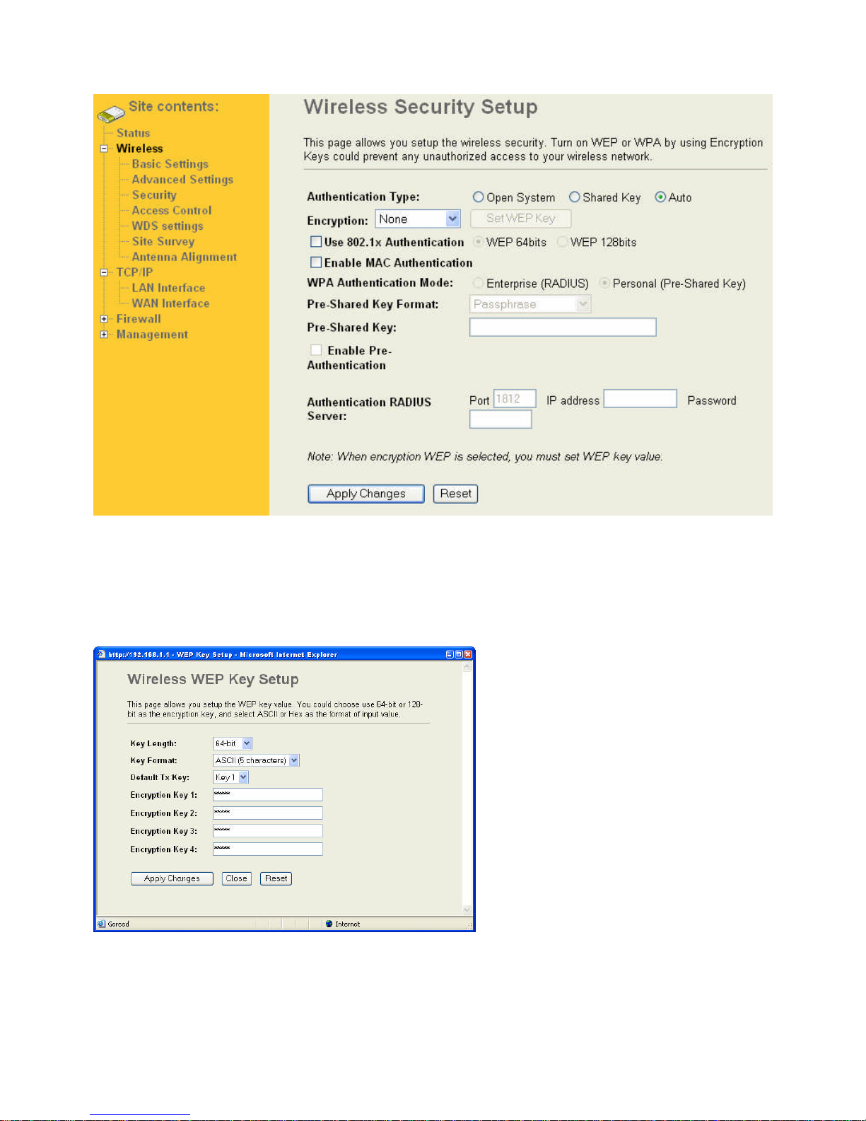
5.3.1 WEP Encryption Setting
Wired Equivalent Privacy (WEP) is implemented in this device to prevent
unauthorized access to your wireless network. The WEP setting must be as same as each client in your wireless
network. For more secure data transmission, you can change encryption type to “WEP” and click the “Set WEP
Key” button to open the “Wireless WEP Key setup” page.
When you decide to use the WEP encryption to secure your WLAN, please refer to the following setting of the WEP
encryption:
5.3.2 64-bit WEP Encryption
64-bit WEP keys are as same as the encryption method of 40-bit WEP. You can input 10 hexadecimal digits (0-9,
Page 19
a-f or A-F) or 5 ACSII chars.
The Default Tx Key field decides which of the four keys you want to use in your WLAN environment.
5.3.3 128-bit WEP Encryption
128-bit WEP Encryption 128-bit WEP keys are as same as the encryption method of 104-bit WEP. You can input
26 hexadecimal digits (0-9, a-f or A-F) or 10 ACSII chars.
The Default Tx Key field decides which of the four keys you want to use in your WLAN environment.
5.3.4 WEP Encryption with 802.1x Setting
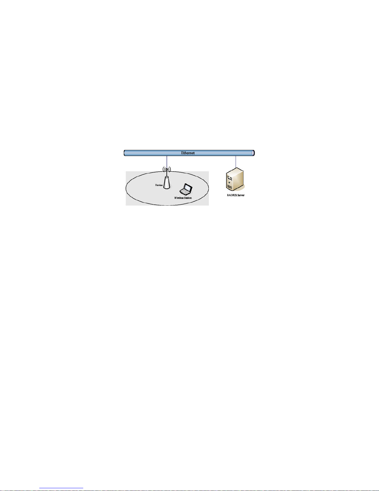
The device supports external RADIUS Server that can secure networks against unauthorized access. If you use
the WEP encryption, you can also use the RADIUS server to check the admission of the users. By this way every
user must use a valid account before accessing the Wireless LAN and requires a RADIUS or other authentication
server on the network. An example is shown as following.
You should choose WEP 64 or 128 bit encryption to fit with your network environment first. Then add user accounts
and the target device to the RADIUS server. In the device , you need to specify the IP address Password (Shared
Secret) and Port number of the target RADIUS server
5.3.5 WPA Encryption Setting
WPA feature provides a high level of assurance for end-users and administrators that their data will remain private
and access to their network restricted to authorized users. You can choose the WPA encryption and select the
Authentication Mode.
5.3.6 WPA Authentication Mode
This device supports two WPA modes. For personal user, you can use the Pre-shared Key to enhance your
security setting. This mode requires only an access point and client station that supports WPA-PSK. For
Enterprise, authentication is achieved via WPA RADIUS Server. You need a RADIUS or other authentication
server on the network.
Enterprise (RADIUS):
When WPA Authentication mode is Enterprise (RADIUS), you have to add user accounts and the target device to
the RADIUS Server. In the device , you need to specify the IP address~ Password (Shared Secret) and Port
number of the target RADIUS server.
Pre-Share Key:
This mode requires only an access point and client station that supports WPA-PSK. The WPA-PSK settings include
Key Format, Length and Value. They must be as same as each wireless client in your wireless network. When Key
format is Passphrase, the key value should have 8~63 ACSII chars. When Key format is Hex, the key value should
have 64 hexadecimal digits (0~9, a~f or A~F)
5.4 Access Control
Access Control provide the possibility to Allow or Deny connections to the Access point. The connections are
filtered based on the MAC address of the Wifi devices that are “trying” to connect to the AP.
Page 20
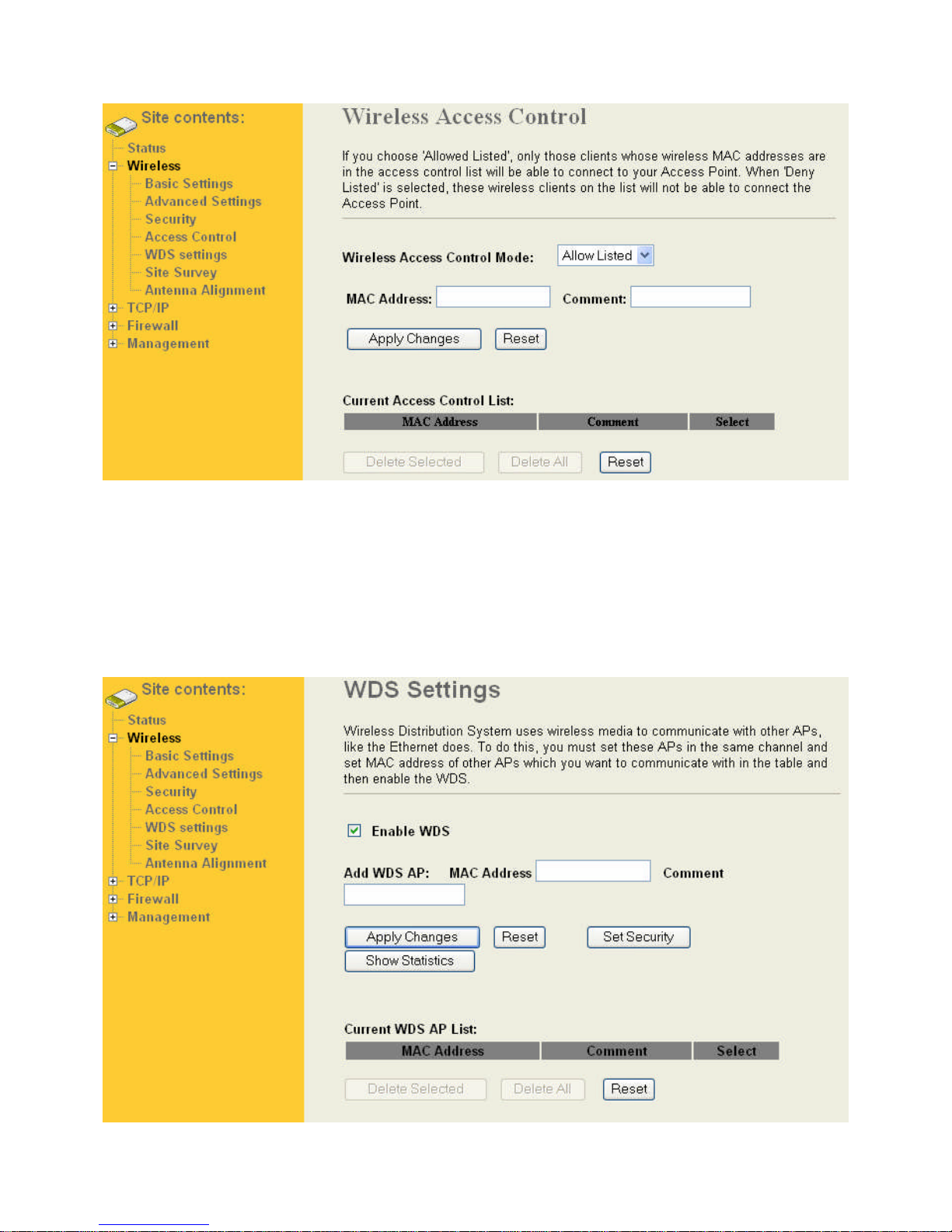
This mode is only available when the wireless radio is configured as an access point. Comment field provide the
option of adding readable text to a MAC address to make recognition easier.
5.5 Configuring WDS
Wireless Distribution System (WDS) uses wireless media to communicate with the other devices, like the Ethernet
does. This function allows one or more remote LANs connect with the local LAN. To do this, you must set these
devices in the same channel and set MAC address of other devices you want to communicate with in the WDS AP
List and then enable the WDS.
Page 21
When you decide to use the WDS to extend your WLAN, please refer the following instructions for configuration.
The bridging devices by WDS must use the same radio channel.
When the WDS function is enabled, all wireless stations can’t connect the device.
If your network topology has a loop, you need to enable the 802.1d Spanning Tree function.
You don’t need to add all MAC address of devices existed in your network to WDS AP List. WDS AP List
only needs to specify the MAC address of devices you need to directly connect to.
The bandwidth of device is limited, to add more bridging devices will split the more bandwidth to every
bridging device.
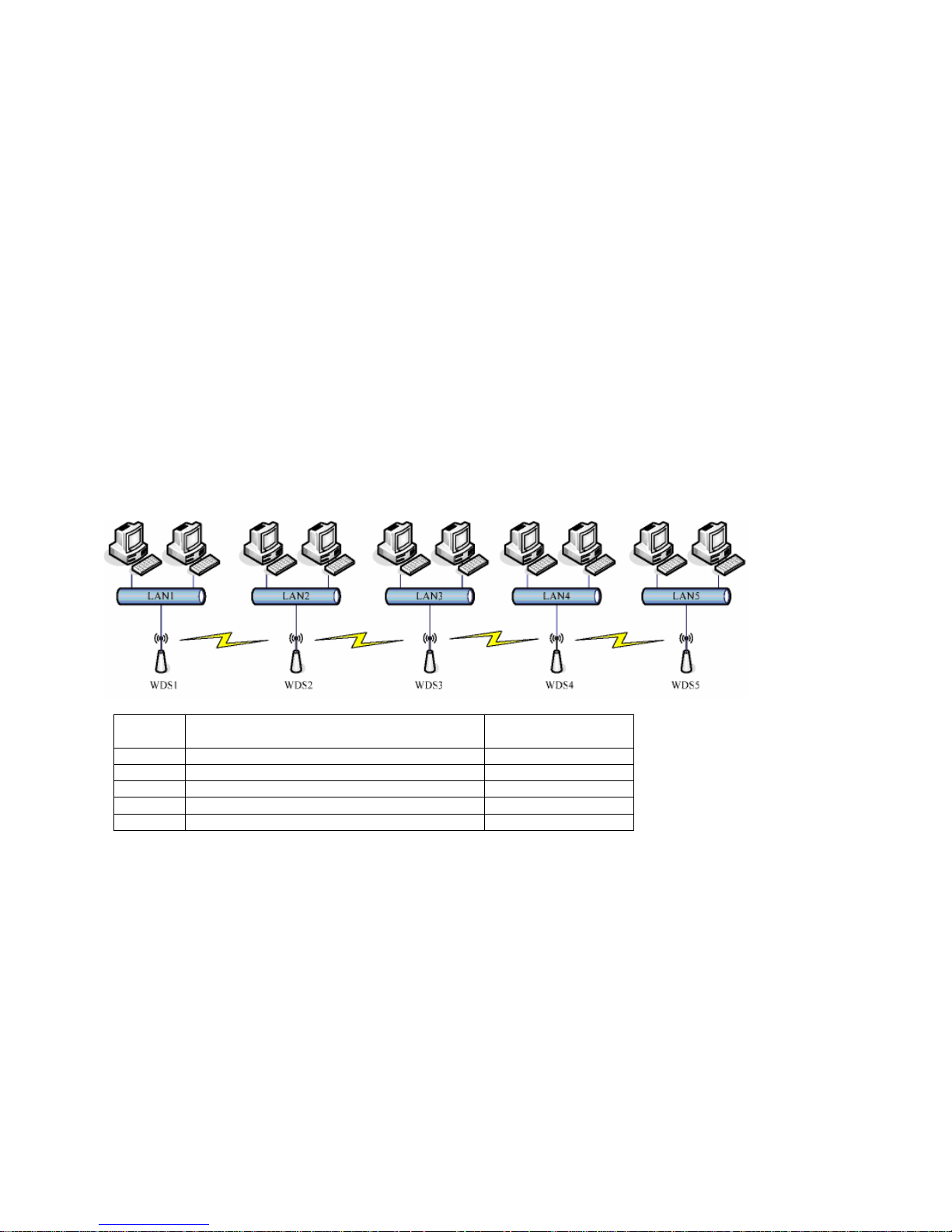
5.6 WDS network topology
In this section, we will demonstrate the WDS network topologies and WDS AP List configuration. You can setup the
four kinds of network topologies:
Bus
Star
Ring
Mesh
In this case, there are five devices with WDS enabled: WDS1, WDS2, WDS3, WDS4 and WDS5.
5.6.1 Bus topology
Device Entries of WDS AP List
Spanning Tree
The MAC Address of WDS2
The MAC Addresses of WDS1 and WDS3
The MAC Addresses of WDS2 and WDS4
The MAC Addresses of WDS3 and WDS5
The MAC
Address of WDS4
Page 22
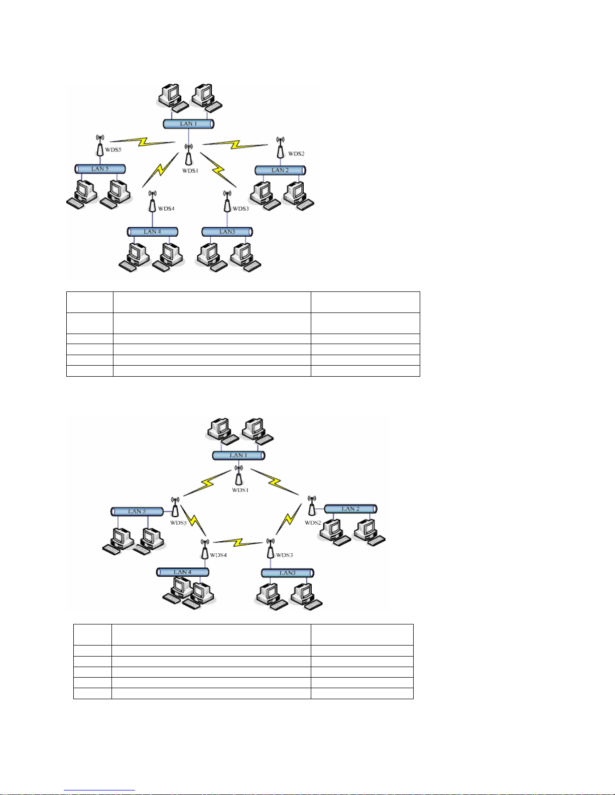
5.6.2 Star topology
Device Entries of WDS AP List
Spanning Tree
WDS1 The MAC Addresses of WDS2, WDS3, WDS4
No
WDS5 The MAC Address of WDS1 No
5.6.3 Ring Topology
Device Entries of WDS AP List
Spanning Tree
e MAC Addresses of WDS3 and WDS5
WDS5 The MAC Addresses of WDS4 and WDS1 Yes
Page 23
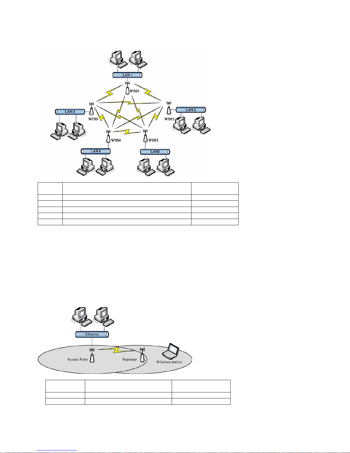
5.6.4 Mesh topology
Device Entries of WDS AP List Spanning Tree
Protocol Required
The MAC Addresses of WDS2, WDS3, WDS4 and
Yes
The MAC Addresses of WDS 1, WD
S3, WDS4 and
Yes
The MAC Addresses of WDS 1, WDS2, WDS4 and
Yes
The MAC Addresses of WDS 1, WDS2, WDS3 and
Yes
The MAC Addresses of WDS 1, WDS2, WDS3 and
Yes
5.7 WDS Application
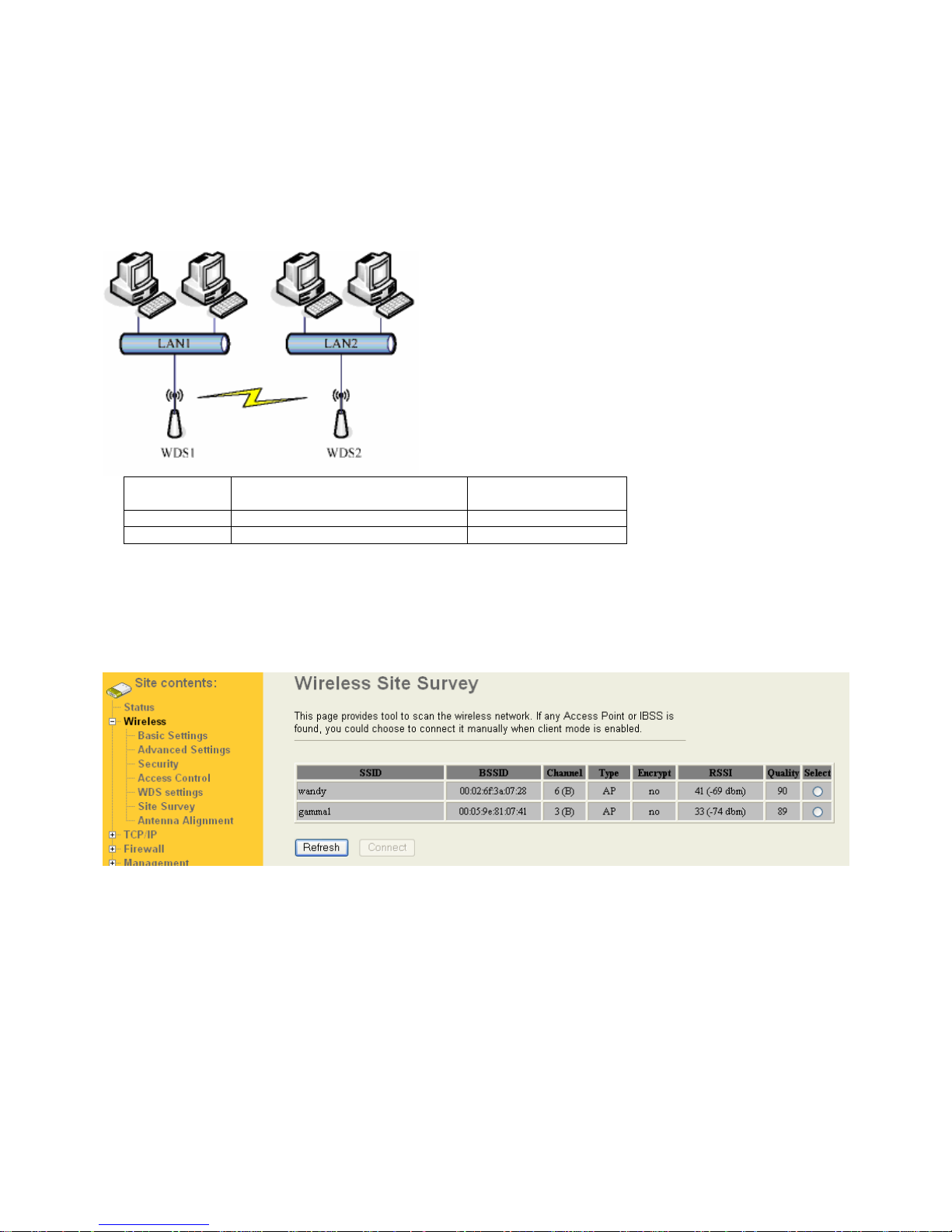
5.7.1 Wireless Repeater
Wireless Repeater can be used to increase the coverage area of another device (Parent AP). Between the Parent
AP and the Wireless Repeater, wireless stations can move among the coverage areas of both devices. When you
decide to use the WDS as a Repeater, please refer the following instructions for configuration.
In AP mode, enable the WDS function.
You must set these connected devices with the same radio channel and SSID.
Choose “WDS+AP” mode.
Using the bus or star network topology.
Description
Entries of WDS AP List
Spanning Tree
Protocol Required
Access Point
Yes
Repeater The MAC Address of Access Point Yes
Page 24
5.7.2 Wireless Bridge
Wireless Bridge can establish a wireless connection between two or more Wired LANs. When you decide to use
the WDS as a Wireless Bridge, please refer the following instructions for configuration.
In AP mode, enable the WDS function.
You must set these connected devices with the same radio channel, but you may use different SSID.
Choose “WDS” mode for only wireless backbone extension purpose.
You can use any network topology, please refer the WDS topology section.
Description
Entries of WDS AP List
Spanning Tree
Protocol Required
WDS1
No
WDS2 The MAC Address of WDS1 No
5.8 Site Survey
This page provides tool to scan the wireless network. If any Access Point or IBSS is found, you could choose to
connect it manually when client mode is enabled.
The RSSI provides the Received Signal Strength Indication . By selecting one AP and pressing connect the Wandy
2R unit will try to connect to the AP.
5.9 Antenna Aligment
This page provides tool to scan the wireless network continuously and provide signal strength.
Page 25
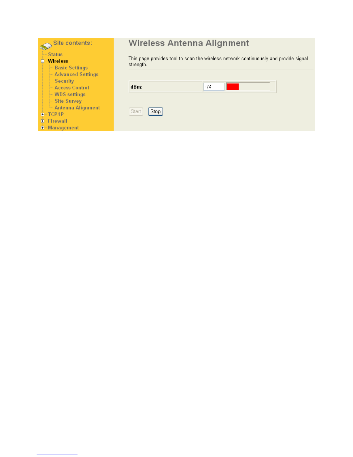
By pressing start the Wandy 2R will constant update the receive signal strength. In this mode it is easy to direct the
unit optimal to the central access point.
Page 26
6 TCP/IP
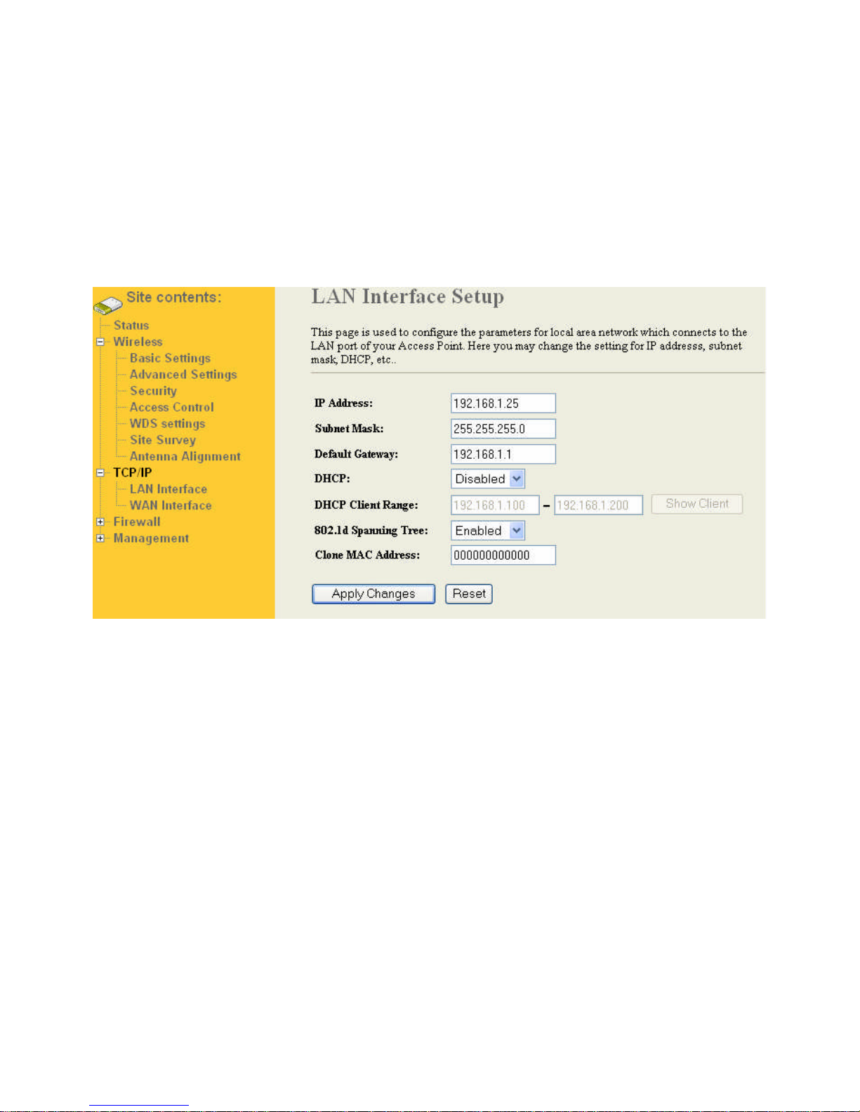
In the TCP/IP menu it is possible to set the IP configuration of the LAN and WAN interface.
6.1 Configuring LAN Interface
This page is used to configure the parameters for local area network which connects to the LAN port of your
Access Point. Here you may change the setting for IP addresss, subnet mask, DHCP, etc..
In the condigurationb there are 3 option
DHCP disabled
DHCP Client
DHCP Server
6.1.1 DHCP disabled
In this mode the IP address of the LAN side will be set to fixed adress
IP address:
The Internet Protocol (IP) address of WAN interface provided by your ISP or MIS. The address will be your network
identifier besides your local network.
Subnet Mask:
The number used to identify the IP subnet network, indicating whether the IP address can be recognized on the
LAN or if it must be reached through a gateway.
Default Gateway:
The IP address of Default Gateway provided by your ISP or MIS. Default Gateway is the intermediate network
device that has knowledge of the network IDs of the other networks in the Wide Area Network, so it can forward the
packets to other gateways until they are delivered to the one connected to the specified destination.
6.1.2 DHCP Client
In this mode the LAN side of the Wandy 2R will get its IP address from a DHCP server in the network. Itr will not be
possible to set the IP address of the device.
6.1.3 DHCP Server
In this mode the IP address of the LAN side will be set to fixed address The DHCP server will provide IP address to
other devices that are connected to the LAN interface of the Wandy 2R
Page 27
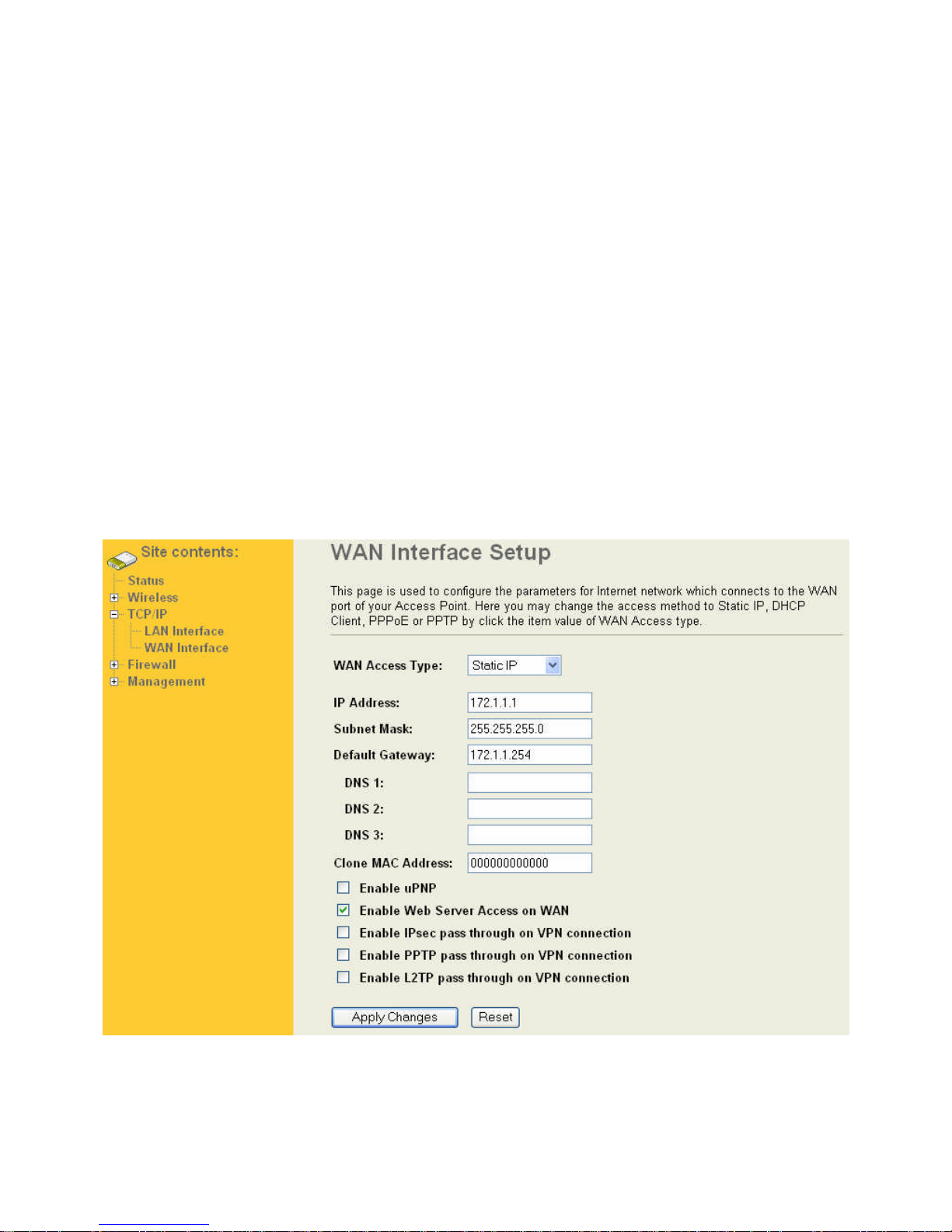
IP address:
The Internet Protocol (IP) address of WAN interface provided by your ISP or MIS. The address will be your network
identifier besides your local network.
Subnet Mask:
The number used to identify the IP subnet network, indicating whether the IP address can be recognized on the
LAN or if it must be reached through a gateway.
Default Gateway:
The IP address of Default Gateway provided by your ISP or MIS. Default Gateway is the intermediate network
device that has knowledge of the network IDs of the other networks in the Wide Area Network, so it can forward the
packets to other gateways until they are delivered to the one connected to the specified destination.
DHCP Client Range:
The IP range that the DHCP server will provide to the client that will are connected to the LAN interface.
Show Client:
This table shows the assigned IP address, MAC address and time expired for each DHCP leased client.
6.2 Configuring WAN Interface
The device supports four kinds of IP configuration for WAN interface,
Static IP,
DHCP Client,
PPPoE
PPTP.
You can select one of the WAN Access Types depend on your ISP required. The default WAN Access Type is
“Static IP”.
6.2.1 Static IP
You can get the IP configuration data of Static-IP from your ISP. And you will need to fill the fields of IP address,
Page 28
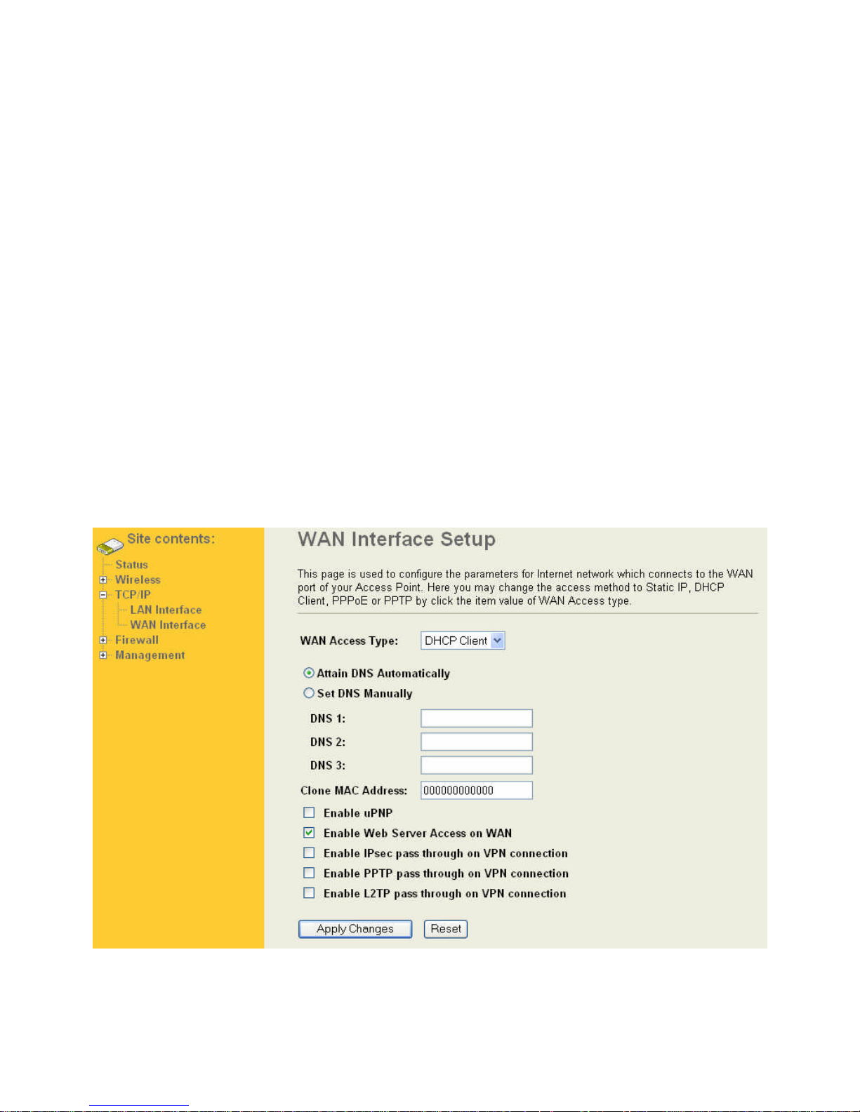
subnet mask, gateway address, and one of the DNS addresses.
IP address:
The Internet Protocol (IP) address of WAN interface provided by your ISP or MIS. The address will be your network
identifier besides your local network.
Subnet Mask:
The number used to identify the IP subnet network, indicating whether the IP address can be recognized on the
LAN or if it must be reached through a gateway.
Default Gateway:
The IP address of Default Gateway provided by your ISP or MIS. Default Gateway is the intermediate network
device that has knowledge of the network IDs of the other networks in the Wide Area Network, so it can forward the
packets to other gateways until they are delivered to the one connected to the specified destination.
DNS 1-3
The IP addresses of DNS provided by your ISP.
DNS (Domain Name Server) is used to map domain names to IP addresses. DNS maintain central lists of domain
name/IP addresses and map the domain names in your Internet requests to other servers on the Internet until the
specified web site is found.
Clone MAC adress
Clone device MAC address to the specify MAC address required by your ISP
Enable uPnP:
Enable uPnP, this function allows the device to be found and configured automatically by the system. (Ex. Window
XP)
6.2.2 DHCP Client (Dynamic IP)
All IP configuration data besides DNS will obtain from the DHCP server when DHCP-Client WAN Access Type is
selected. It is possible to receive the DNS from the DHCP server.
Page 29
6.2.3 PPPoE
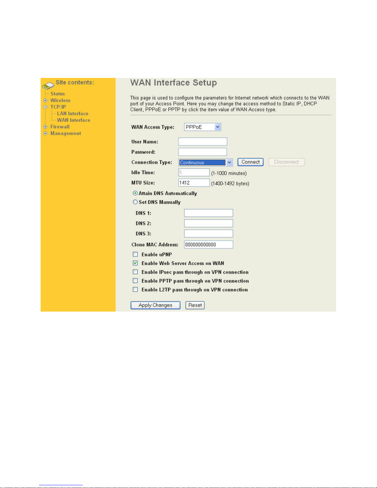
When the PPPoE((Point to Point Protocol over Ethernet) WAN Access Type is selected, you must fill the fields of
User Name, Password provided by your ISP. The IP configuration will be done when the device successfully
authenticates with your ISP
User Name
The account provided by your ISP
Password
The password for your account.
Connection Type
“Continuous “ : connect to ISP permanently
“Manual” : Manual connect/disconnect to ISP
“On-Demand” : Automatically connect to ISP when user need to access the Internet.
Idle Time
The number of inactivity minutes to disconnect from ISP. This setting is only available when “Connect on Demand”
connection type is selected.
MTU Size
Maximum Transmission Unit, 1412 is the default setting, you may need to change the MTU for optimal
performance with your specific ISP.
DNS1-3
The IP addresses of DNS provided by your ISP.
DNS (Domain Name Server) is used to map domain names to IP addresses. DNS maintain central lists of domain
name/IP addresses and map the domain names in your Internet requests to other servers on the Internet until the
specified web site is found.
Page 30
Clone device MAC
Clone device MAC address to the specify MAC address required by your ISP.
Enable UPnP, this function allows the device to be found and configured automatically by the system. (Ex. Window
XP)
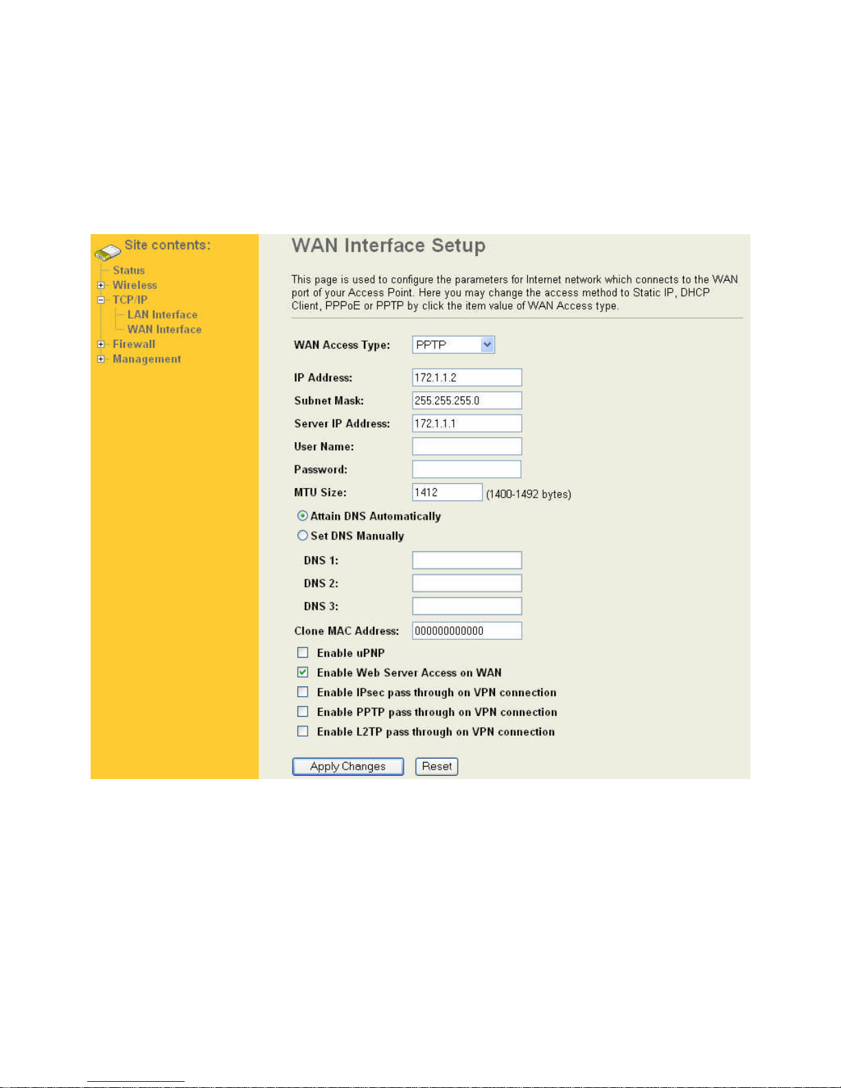
6.2.4 PPTP
Point to Point Tunneling Protocol (PPTP) is a service that applies to connections in Europe only
IP Address:
The Internet Protocol (IP) address of WAN interface provided by your ISP or MIS. The address will be your network
identifier besides your local network.
Subnet Mask:
The number used to identify the IP subnet network, indicating whether the IP address can be recognized on the
LAN or if it must be reached through a gateway.
Server IP Address:
The IP address of PPTP server (Default Gateway)
User Name:
The account provided by your ISP
Password:
The password of your account
MTU Size:
Page 31

Maximum Transmission Unit, 1412 is the default setting, you may need to change the MTU for optimal
performance with your specific ISP.
DNS1-:
The IP addresses of DNS provided by your ISP.
DNS (Domain Name Server) is used to map domain names to IP addresses. DNS maintain central lists of domain
name/IP addresses and map the domain names in your Internet requests to other servers on the Internet until the
specified web site is found.
Clone MAC Address:
Clone device MAC address to the specify MAC address required by your ISP.
Enable uPnP:
Enable uPnP, this function allows the device to be found and configured automatically by the system. (Ex. Window
XP)
Page 32
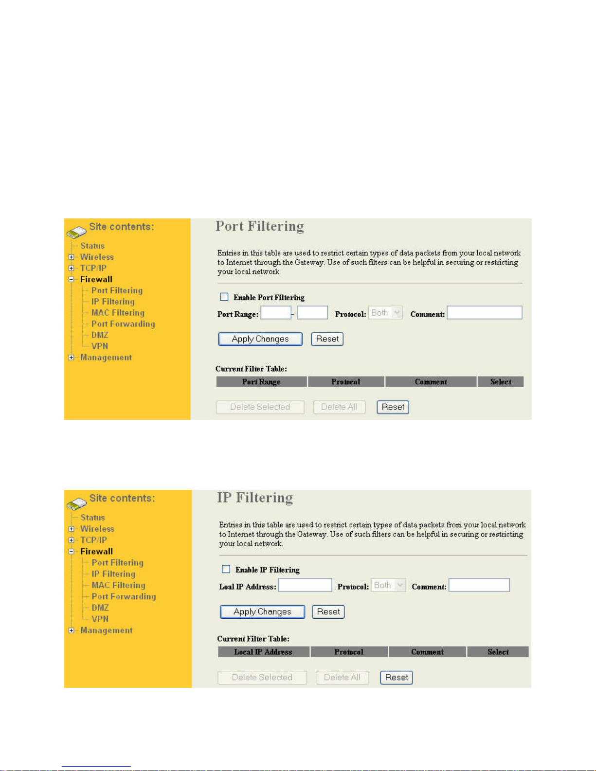
7 Firewall
Filtering function is used to block packets from LAN to WAN. The device supports three kinds of filter Port Filtering,
IP Filtering and MAC Filtering. All the entries in current filter table are used to restrict certain types of packets from
your local network to through the device. Use of such filters can be helpful in securing or restricting your local
network.
7.1 Port Filtering
When you enable the Port Filtering function, you can specify a single port or port ranges in current filter table. Once
the source port of outgoing packets match the port definition or within the port ranges in the table, the firewall will
block those packets from LAN to WAN.
7.2 IP Filtering
When you enable the IP Filtering function, you can specify local IP Addresses in current filter table. Once the
source IP address of outgoing packets match the IP Addresses in the table, the firewall will block this packet from
LAN to WAN.
Page 33
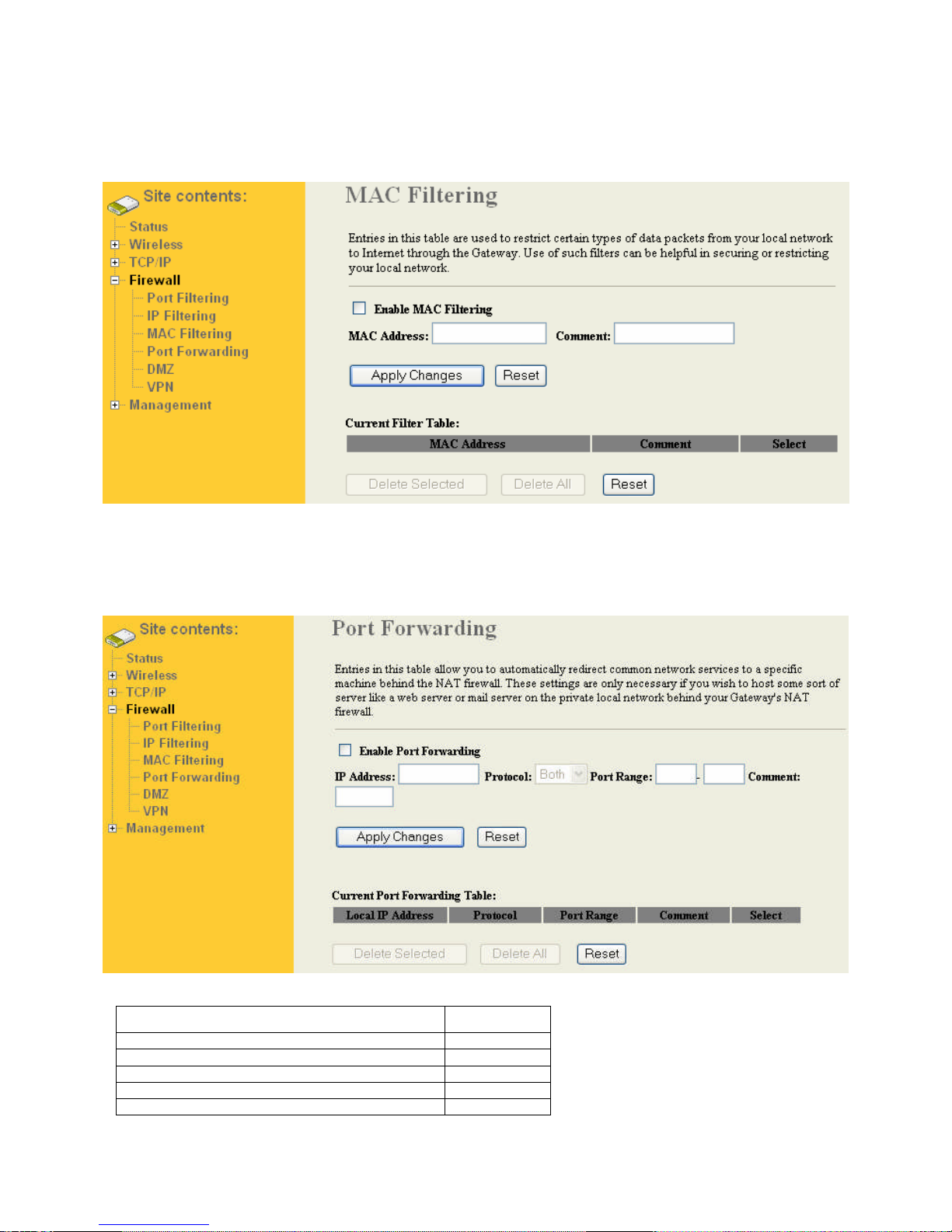
7.3 MAC Filtering
When you enable the MAC Filtering function, you can specify the MAC
Addresses in current filter table. Once the source MAC Address of outgoing packets match the MAC Addresses in
the table, the firewall will block this packet from LAN to WAN.
7.4 Port Forwarding (Virtual Server)
This function allows you to automatically redirect common network services to a specific machine behind the NAT
firewall. These settings are only necessary if you wish to host some sort of server like a web server or mail server
on the private local network behind the device's NAT firewall.
The most often used port numbers are shown in the following table.
Services Port Number
Page 34
Finger 79
to
723
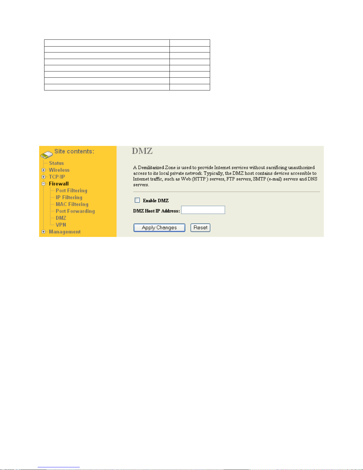
7.5 DMZ
A Demilitarized Zone is used to provide Internet services without sacrificing unauthorized access to its local private
network. Typically, the DMZ host contains devices accessible to Internet traffic, such as Web (HTTP ) servers, FTP
servers, SMTP (e-mail) servers and DNS servers. So that all inbound packets will be redirected to the computer
you set. It also is useful while you run some applications (ex. Internet game) that use uncertain incoming ports
Page 35
8 Management
In this menu it is possible to configure the operation mode of the Wandy 2R. Monitor functions as logging and
save/resore config with new firmware upload functions provide the tools to keep the unit up to date.
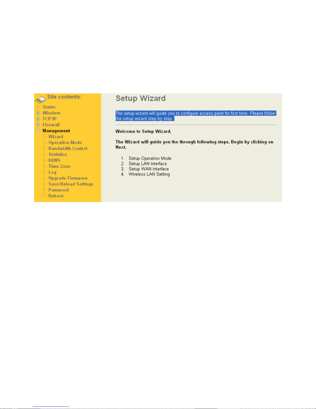
8.1 Wizard
The setup wizard will guide you to configure access point for first time. Please follow the setup wizard step by step.
8.2 Operation Mode
You can setup different modes to LAN and WLAN interface for NAT and bridging function.
Page 36
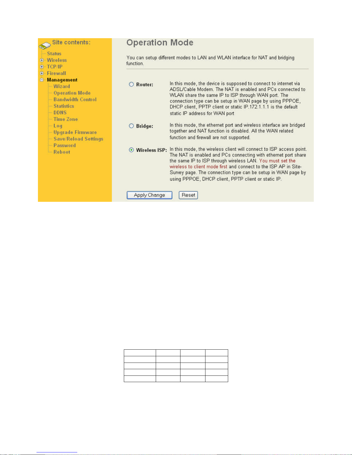
8.2.1 Router
The wired Ethernet (WAN) port is used to connect with ADSL/Cable modem and the wireless NIC is used for your
private WLAN. The NAT is existed between the 2 NIC and all the wireless clients share the same public IP address
through the WAN port to ISP. The default IP configuration for WAN port is static IP. You can access the web server
of device through the default WAN IP address 172.1.1.1 and modify the setting base on your ISP requirement.
8.2.2 Bridge
The wired Ethernet and wireless NIC are bridged together. Once the mode is selected, all the WAN related
functions will be disabled.
8.2.3 WISP (Wireless ISP)
This mode can let you access the AP of your wireless ISP and share the same public IP address form your ISP to
the PCs connecting with the wired Ethernet port of the device. To use this mode, first you must set the wireless
radio to be client mode and connect to the AP of your ISP then you can configure the WAN IP configuration to meet
your ISP requirement.
The following table shows the supporting combination of operation and wireless radio modes.
Bridge Router WISP
AP Yes Yes No
WDS Yes Yes No
Client Yes No Yes
AP+WDS Yes Yes No
Page 37
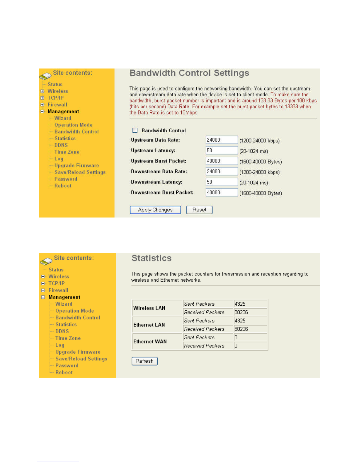
8.3 Bandwidth Control
This page is used to configure the networking bandwidth. You can set the upstream and downstream data rate
when the device is set to client mode.
8.4 Statistics
This page shows the packet counters for transmission and reception regarding to wireless and Ethernet networks.
8.5 Dynamic DNS Setting
Dynamic DNS is a service, that provides you with a valid, unchanging, internet domain name (an URL) to go with
that (possibly everchanging) IP-address.
Page 38
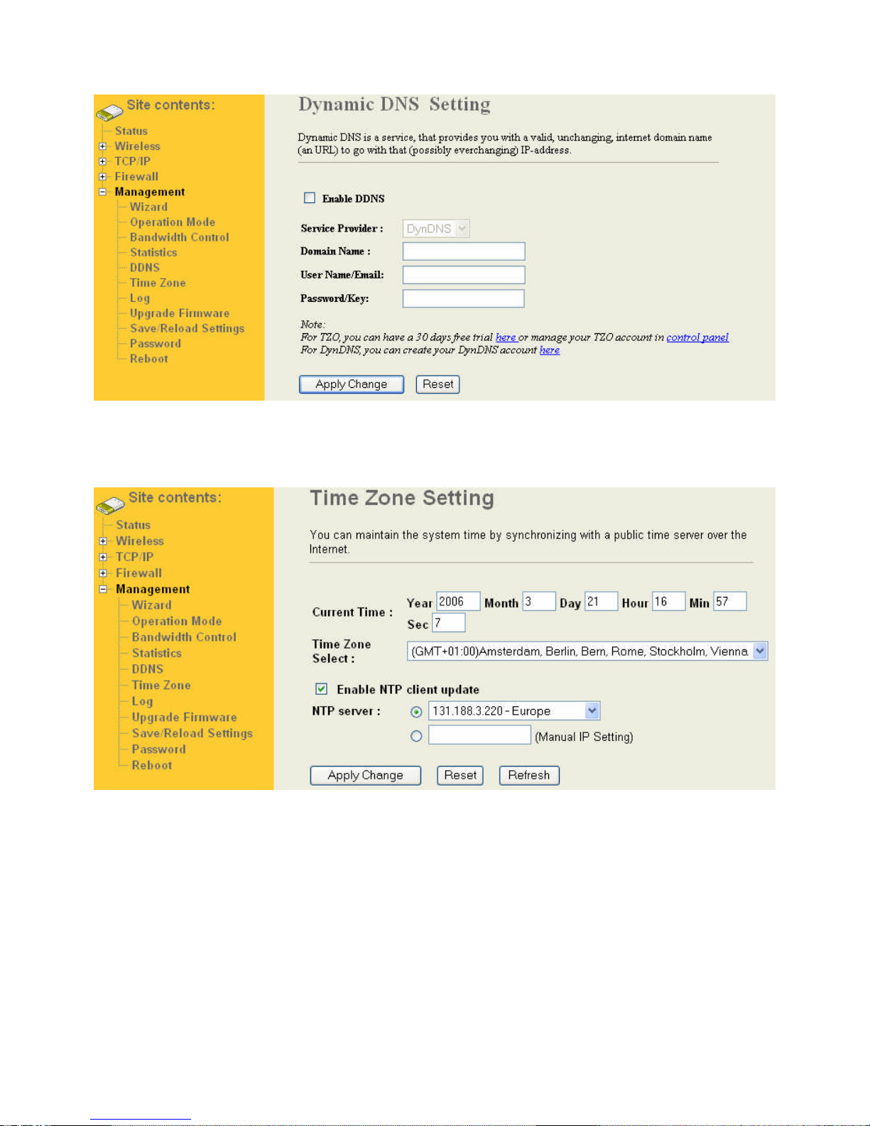
8.6 Time Zone
The Wandy 2R can maintain the system time by synchronizing with a public time server over the Internet.
8.7 Log
The Wandy 2R has a log funtion. On this page you can set what to log en where the unit must send its log to. A
remote log server is possible by setting the IP address of the log server.
Page 39
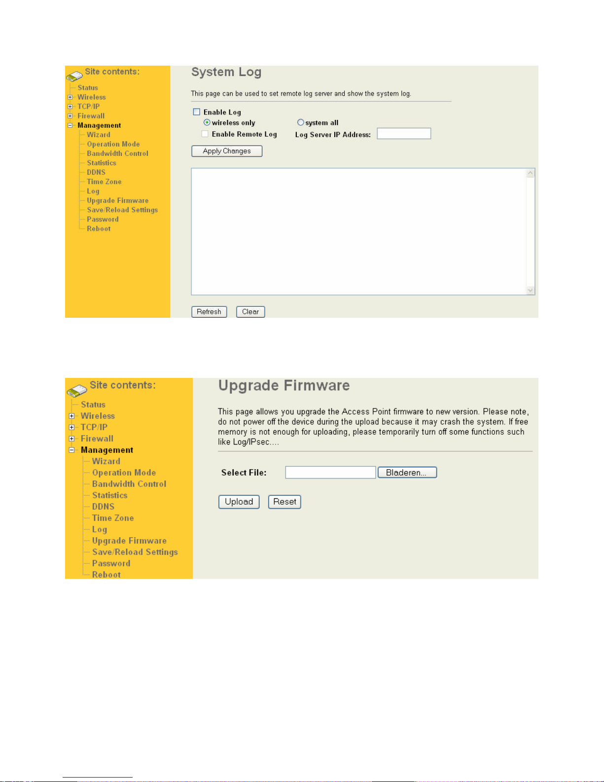
8.8 Upgrade Firmware
This page allows you upgrade the Access Point firmware to new version.
8.9 Save/Reload Settings
This page allows you save current settings to a file or reload the settings from the file which was saved previously.
Besides, you could reset the current configuration to factory default.
Page 40
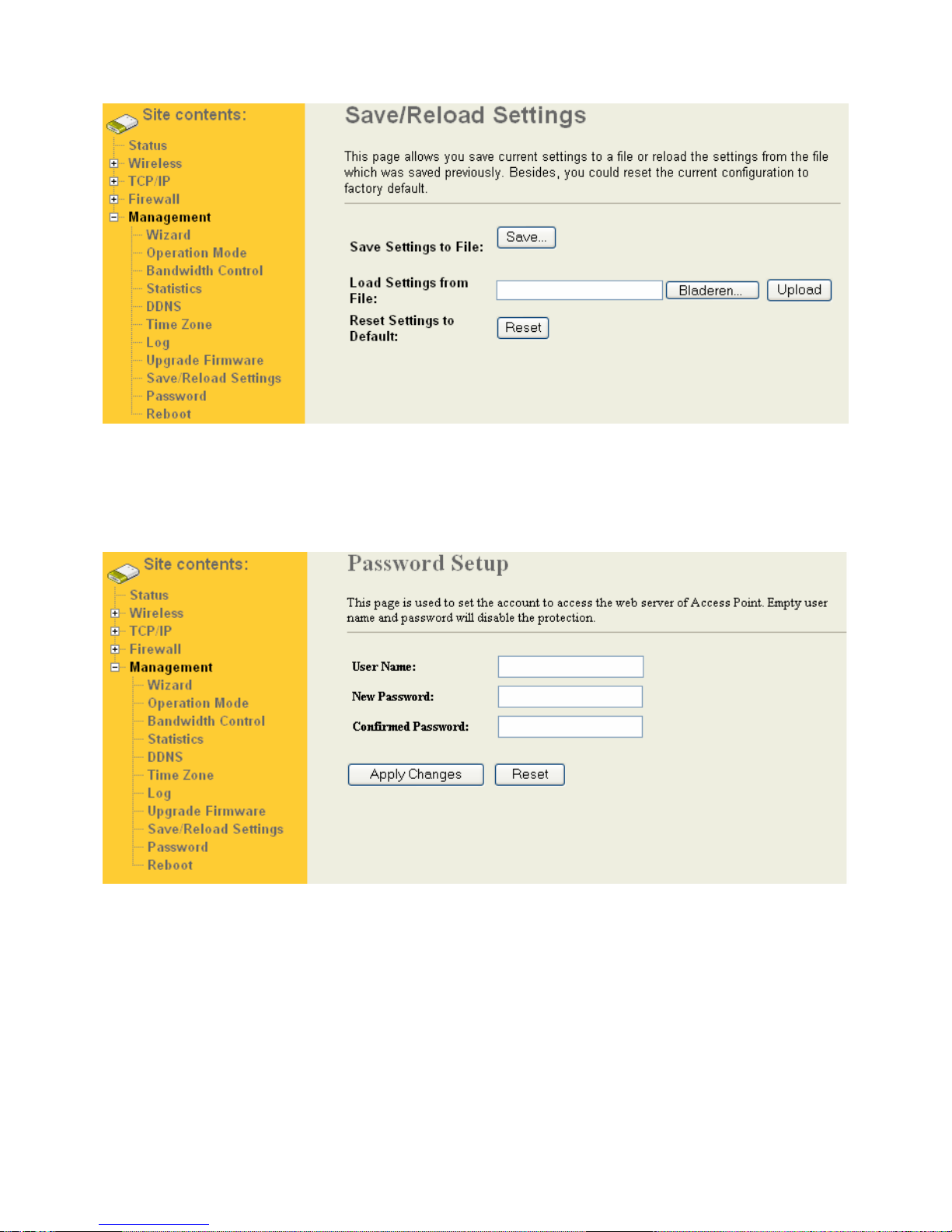
8.10 Password
This page is used to set the account to access the web server of Access Point. Empty user name and password
will disable the protection.
The username and password must be smaller then 20 characters. Best to use a combination of numbers and
characters.
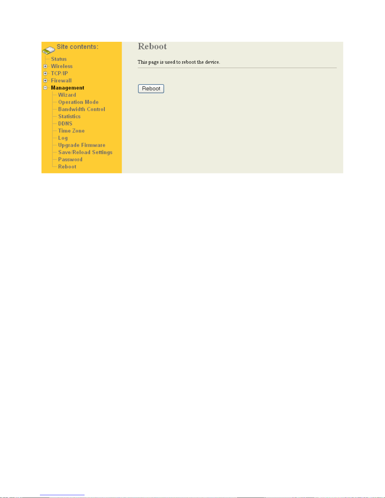
8.11 Reboot
This page is used to reboot the device. It will take up to 55 sec to fully reboot the device.
Page 41
Page 42

9 SSH login
Start a SSH(Secure Shell) client session to login the device
The SSH server daemon inside device uses well-known TCP port 22. User must use SSH client utility such like
Putty to login the device.
The default password for user “root” is “wandy”, once user login the device then can change the password by CLI
command.
Execute CLI program
This program won’t execute automatically when user login the device. User must manually execute it by typing the
case-sensitive command “cli”. Please note that any modified settings won’t save permanently until user “Apply
Changes to Flash” or reboot it. The new settings modified by CLI will take effect after rebooting the device.
Before Start to Configure
To configure the device there is a web-browser interface. To access the web interfaces, make sure you are using a
computer connected to the same network as the device. The default IP address of the device is 192.168.1.1, and
the subnet-mask is 255.255.255.0.
The default configuration of the device is WISP mode.
The WISP mode can let you access the AP of your wireless ISP and share the same public IP address form your
ISP to the PCs connecting with the wired Ethernet port of the device.
Please note that the DHCP server inside the device is default to up and running with the IP range 192.168.1.100-
192.168.1.200. Do not have multiple DHCP servers in your subnet, otherwise it will cause abnormal situation.
Inside the CD, we provide the device auto-discovery tool, the tool can detect the device even your PC is not in the
same subnet as the device in case the IP address of device is changed and forgot by user. The tool only can
discover the device in your local area network.
The Wandy 2R unit can operate in many more modes then WISP with routing function of Wifi Brigde.
More information about these modes in chapter.
 Loading...