

Page 1
Operati n g Instructions to Amplifier Electronics SD7
OPERATING INSTRUCTIONS
AMPLIFI ER MODULE SD 7
Wandfluh AG
Postfach
CH-3714 Frutigen
Tel: +41 33 672 72 72
Fax: +41 33 672 72 12
Email: sales@wandfluh.com
Internet: www.wandfluh.com
Page 1
Edition 17 33
SD7_OperatingInstructions_
Page 2

Operati n g Instructions to Amplifier Electronics SD7
Contents
1 General i n formation 4
2 Product description 5
... . ......................................... ................................................................................. ................................................... 52.1 General
... . ......................................... ................................................................................. ................................................... 52.2 Field of application
... . ......................................... ................................................................................. ................................................... 52.3 Conformity
... . ......................................... ................................................................................. ................................................... 52.4 Labeling of the product
... . ......................................... ................................................................................. ................................................... 62.5 Type code
... . ......................................... ................................................................................. ................................................... 72.6 Technical data
... . ......................................... ................................................................................. ................................................... 102.7 Block diagram
3 Sa fety rule s 18
... . ......................................... ................................................................................. ................................................... 183.1 Installation / Commissioning / Parameterisation
4 Construction and F unction 19
... . ......................................... ................................................................................. ................................................... 194.1 Introduction
... . ......................................... ................................................................................. ................................................... 194.2 Description of the Function
... . ......................................... ................................................................................. ................................................... 204.3 Characteristic optimisation
... . ......................................... ................................................................................. ................................................... 214.4 State machine
... . ......................................... ................................................................................. ................................................... 224.5 Operating mode
... . ......................................... ................................................................................. ................................................... 224.6 Analogue inputs
... . ......................................... ................................................................................. ................................................... 244.7 Cablebreak detection
... . ......................................... ................................................................................. ................................................... 254.8 Digital inputs
... . ......................................... ................................................................................. ................................................... 254.9 Outputs
... . ......................................... ................................................................................. ................................................... 254.10 Internal signals
... . ......................................... ................................................................................. ................................................... 264.11 M ode of operation
... . ......................................... ................................................................................. ................................................... 284.12 Power reduction
5 Operating and i n di cating elem ents 30
... . ......................................... ................................................................................. ................................................... 305.1 General
... . ......................................... ................................................................................. ................................................... 305.2 Screw terminator v iew
... . ......................................... ................................................................................. ................................................... 345.3 Control elements
6 Commissioning 40
... . ......................................... ................................................................................. ................................................... 406.1 Connection instructions
... . ......................................... ................................................................................. ................................................... 426.2 Connection ex amples
7 Settings 46
... . ......................................... ................................................................................. ................................................... 467.1 Introduction
... . ......................................... ................................................................................. ................................................... 467.2 Assignment of the inputs/outputs
... . ......................................... ................................................................................. ................................................... 477.3 Parameter inconsistency
... . ......................................... ................................................................................. ................................................... 487.4 Tips for the first commissioning
... . ......................................... ................................................................................. ................................................... 497.5 Inputs/outputs according to Wandfluh standard
... . ......................................... ................................................................................. ................................................... 497.6 Default setting of the parameters
... . ......................................... ................................................................................. ................................................... 527.7 Parameters setting
... . ......................................... ................................................................................. ................................................... 717.8 Menu File
... . ......................................... ................................................................................. ................................................... 757.9 Menu Communication
... . ......................................... ................................................................................. ................................................... 767.10 M enu Configuration
... . ......................................... ................................................................................. ................................................... 827.11 M enu Commands
... . ......................................... ................................................................................. ................................................... 877.12 Fieldbus-Menu
... . ......................................... ................................................................................. ................................................... 887.13 M enu Analysis
... . ......................................... ................................................................................. ................................................... 987.14 M enu Help
8 Syste m does not work 100
... . ......................................... ................................................................................. ................................................... 1008.1 Procedure
9 PASO Installation and Operation 101
... . ......................................... ................................................................................. ................................................... 1019.1 System presupposition
... . ......................................... ................................................................................. ................................................... 1019.2 Installation
... . ......................................... ................................................................................. ................................................... 1029.3 PASO Update
... . ......................................... ................................................................................. ................................................... 1039.4 Connection to the Wandfluh card
... . ......................................... ................................................................................. ................................................... 1039.5 Mode "Off Line" / "On Line"
... . ......................................... ................................................................................. ................................................... 1049.6 Communication start up
... . ......................................... ................................................................................. ................................................... 1069.7 Communication interruption
... . ......................................... ................................................................................. ................................................... 1079.8 Program description
... . ......................................... ................................................................................. ................................................... 1089.9 Starting of PASO
... . ......................................... ................................................................................. ................................................... 1109.10 St ore parameter
... . ......................................... ................................................................................. ................................................... 1109.11 Limiting v alue error
... . ......................................... ................................................................................. ................................................... 1119.12 Used analog input not compatible to the selected signal type
Wandfluh AG
Postfach
CH-3714 Frutigen
Tel: +41 33 672 72 72
Fax: +41 33 672 72 12
Email: sales@wandfluh.com
Internet: www.wandfluh.com
Page 2
Edition 17 33
SD7_OperatingInstructions_
Page 3

Operati n g Instructions to Amplifier Electronics SD7
... . ......................................... ................................................................................. ................................................... 1119.13 Description of Commands
10 Disposal 112
11 Accessories 113
12 Additiona l i nform ation 114
Wandfluh AG
Postfach
Tel: +41 33 672 72 72
Fax: +41 33 672 72 12
Email: sales@wandfluh.com
Internet: www.wandfluh.com
CH-3714 Frutigen
Page 3
Edition 17 33
SD7_OperatingInstructions_
Page 4

Operati n g Instructions to Amplifier Electronics SD7
1 General information
This operating instructions mak es i t possible to use the SD7-Electronics s afely and ac c ording t o specification. The
operating instructions includes instructions which Wandfluh as the manufacturer, or its resale organisations
(Wandfl uh sister companies or distributors), provide to users within their duty t o ins t ruct .
For this purpose, the operati ng inst ruct i ons m ainly inc l udes:
· information about use acc ording to specification, i ns t allat ion and commis sioning of t he SD7-Electronics
· information about safety in dealing with control.
Wandfluh AG
Postfach
CH-3714 Frutigen
Tel: +41 33 672 72 72
Fax: +41 33 672 72 12
Email: sales@wandfluh.com
Internet: www.wandfluh.com
Page 4
Edition 17 33
SD7_OperatingInstructions_
Page 5

Operati n g Instructions to Amplifier Electronics SD7
· Part number
· Serial number
· Software version
· Firmware versi on
· Card t ype
· Device configuration
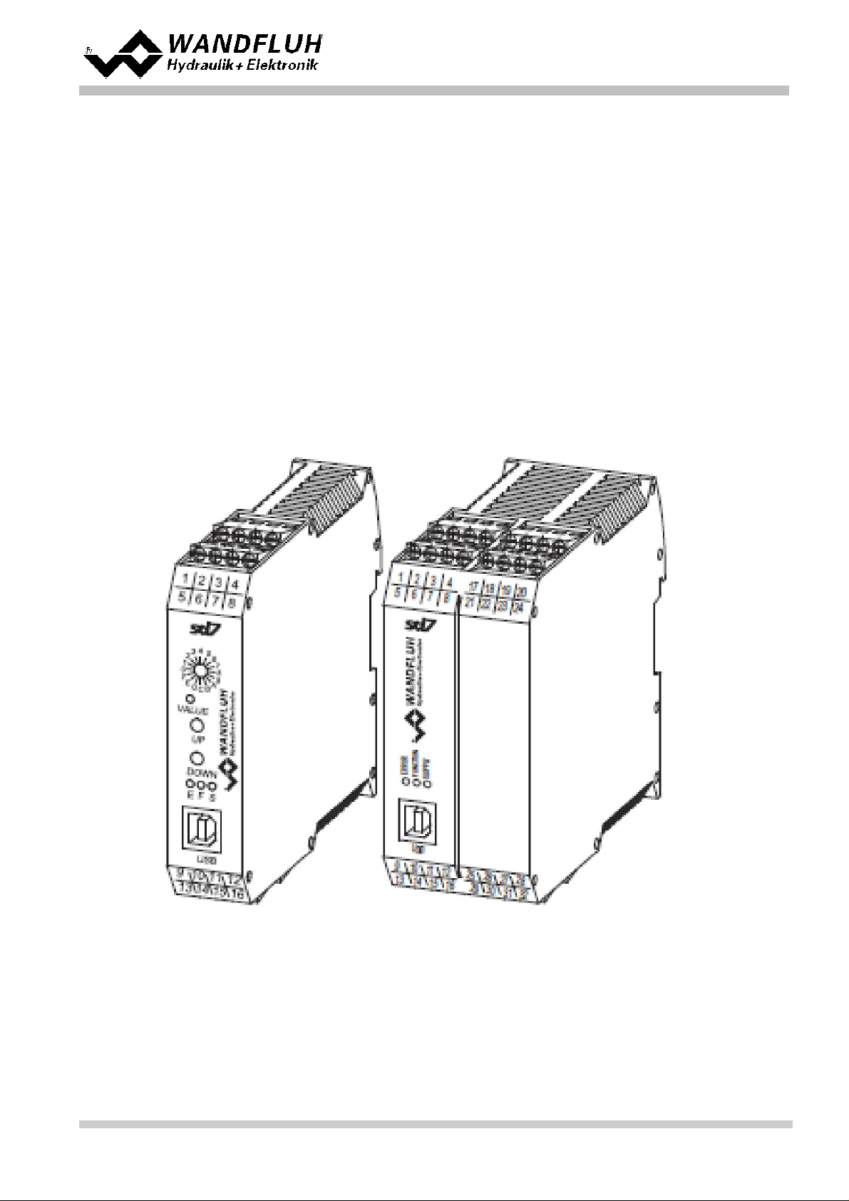
2 Product description
2.1 General
The SD7-Electronics is integrated in a case for top-hat rail fastening. The connections are provided by terminal
sc rew blocks .
2.2 Field of appli cation
The field of applicati on of the SD6-E lec t ronics is s it uated in the industrial field.
2.3 Conformity
The SD7-Electronics have been developed and tested in accordance wit h the lates t t echnic al s t andards . A pplied in
particular was the EU Guideline 2004/108/EG (EM C Guideline).
2.4 Labeling of the product
Wit h the PC parameterisation software PASO SD7, the following information can be directly read-off the SD7Elect ronics (= elec t ronic t ype code):
Wandfluh AG
Postfach
CH-3714 Frutigen
Tel: +41 33 672 72 72
Fax: +41 33 672 72 12
Email: sales@wandfluh.com
Internet: www.wandfluh.com
Page 5
Edition 17 33
SD7_OperatingInstructions_
Page 6

2.5 Type code
Operati n g Instructions to Amplifier Electronics SD7
Wandfluh AG
Postfach
CH-3714 Frutigen
Tel: +41 33 672 72 72
Fax: +41 33 672 72 12
Email: sales@wandfluh.com
Internet: www.wandfluh.com
Page 6
Edition 17 33
SD7_OperatingInstructions_
Page 7
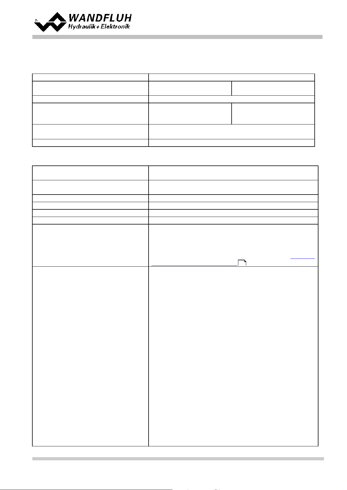
2.6 Technical data
Design
Integrated in electronic case for top-hat rail cl amping
Dimension
Basic amplifier
Enhanced amplifier
105 x 114 x 22.5
105 x 114 x 45mm
Installation
aufs chnappbar auf Hutschiene
Weight
Basic amplifier
Enhanced amplifier
amplifier with P rofibus
130g
130g
240g
Connection
Terminal screw blocks, m ax dimensi on 2.5mm
2
1 USB interface (connector type B)
Protection cl ass
IP30 acc. t o E N 60 529
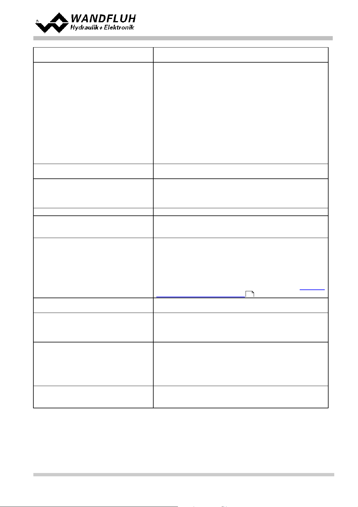
Supply vol ta g e
(dependin g on the type)
24 VDC
or 12 VDC
Voltage range
Supply voltage 24 VDC:
Supply voltage 12 VDC:
21 ... 30 VDC
10,5 ... 15 VDC
Ripple on supply voltage
< ±5 %
Fuse
Customer must int egrate a slow fuse into his elec t ric al system
Tempe rature d ri ft
< 1% with DT = 40°C
No loa d current
40 ... 50 mA
Ma x. solenoi d current
24VDC vers ion
12VDC vers ion
1.8 A
2.3 A
The tot al s olenoid current of s i mult aneously powered solenoids
depends on the ambient temperature (refer to section "Solenoid
outputs and ambient temperat ure" )
Analog ue i nputs
2 (Basic vers ion) resp. 4 (Enhanced version) different i al inputs
Inputs 1 and 2 = 10-Bit resolution
Inputs 3 and 4 = 16-Bit resolution
All inputs are not galvanically separat ed
SD7XXXDX0-AA
SD7XXXDX1-AX
SD7XXXDX2-AX
SD7XXXDX4-BX
SD7XXXDX5-BX
SD7XXXDX6-BX
Analogue i nputs 1:
Analogue i nputs 2:
Analogue i nputs 1:
Analogue i nputs 2:
Analogue i nputs 1:
Analogue i nputs 2:
Analogue i nputs 1:
Analogue i nputs 2:
Analogue i nputs 3:
Analogue i nputs 4:
Analogue i nputs 1:
Analogue i nputs 2:
Analogue i nputs 3:
Analogue i nputs 4:
Analogue i nputs 1:
Analogue i nputs 2:
0...±10VDC
0... 20mA, 4. . .20mA
0...±10VDC
0...±10VDC *
0... 20mA, 4. . .20mA
0... 20mA, 4. . .20mA
0...±10VDC
0... 20mA, 4. . .20mA
0...±10VDC
0... 20mA, 4. . .20mA
0...±10VDC
0...±10VDC *
0...±10VDC
0...±10VDC
0... 20mA, 4. . .20mA
0... 20mA, 4. . .20mA
2.6.1 General specifica tio ns
2.6.2 Electrical specifications
Operati n g Instructions to Amplifier Electronics SD7
9
Wandfluh AG
Postfach
CH-3714 Frutigen
Tel: +41 33 672 72 72
Fax: +41 33 672 72 12
Email: sales@wandfluh.com
Internet: www.wandfluh.com
Page 7
Edition 17 33
SD7_OperatingInstructions_
Page 8
Operati n g Instructions to Amplifier Electronics SD7
Supply vol ta g e
(dependin g on the type)
24 VDC
or 12 VDC
SD7XXXDX7-BX
SD7XXXDX8-BX
Analogue i nputs 3:
Analogue i nputs 4:
Analogue i nputs 1:
Analogue i nputs 2:
Analogue i nputs 3:
Analogue i nputs 4:
Analogue i nputs 1:
Analogue i nputs 2:
Analogue i nputs 3:
Analogue i nputs 4:
0... 20mA, 4. . .20mA
0... 20mA, 4. . .20mA
0...±10VDC
0...±10VDC *
0... 20mA, 4. . .20mA
0... 20mA, 4. . .20mA
0... 20mA, 4. . .20mA
0... 20mA, 4. . .20mA
0...±10VDC
0...±10VDC
*) 0...10VDC at SD7 with Profibus
Input re sistance
Voltage input against ground
Burden for current i nput
> 18 kOhm
= 250 Ohm
Digital inp uts
2 (Basic vers ion) resp. 8 (Enhanced
version) input s high-active
Switc hing threshold high
Switc hing threshold low
6 - 30VDC
0 - 1VDC
Se ri al interfa ce
1 USB interface (Connect or Type B)
Stabili sed output voltage
Supply voltage 24 VDC:
Supply voltage 12 VDC:
+ 10 VDC
+ 8 VDC
max. load 30 mA
Solenoi d curre n t
Minimum c urrent Imin einstellbar
Maxim um c urrent Imax einstellbar
Supply volt age 24 VDC:
Supply volt age 12 VDC:
0 ... 950 mA
Imin ... max. 1.8 A
Imin ... max. 2.3 A
The tot al s olenoid current of s i mult aneously powered solenoids
depends on the ambient temperature (refer to section "Solenoid
outputs and ambient temperat ure" )
Dither
Frequency adjustable
Level adjustable
20 ... 250 Hz
0 ... 200 mA
Digital outputs
2 (Basic vers ion) resp. 4 (Enhanced version)
outputs Lowside Switch
Umax
Imax
40 VDC
-0.7 A
Analog output
(only Enhanced versi on )
without HART:
Output voltage
max. load
with HART:
Output current
max. V olt age
+/– 10 VDC
+/– 3 mA
0 ... 20 mA
12 VDC
EMC
Immunity
Emission
EN 61000-6-2
EN 61000-6-4
Wandfluh AG
Postfach
CH-3714 Frutigen
Tel: +41 33 672 72 72
Fax: +41 33 672 72 12
Email: sales@wandfluh.com
Internet: www.wandfluh.com
9
SD7_OperatingInstructions_
Page 8
Edition 17 33
Page 9

Operati n g Instructions to Amplifier Electronics SD7
Storage
Packing:
The module must be s t ored in the original packing
Temperature range:
-25 ... + 85° C
Resistanc e t o alkali and acid:
The module must be protected against alkalis and
acids
In opera ti on
Temperature range:
-20 ... + 70° C
The tot al s olenoid current of s i mult aneously
powered solenoids depends on the ambient
temperature (refer to section "S olenoid outputs
and ambient t emperature" )
Resistanc e t o alkali and acid:
The module must be protected against alkalis and
acids
2.6.3 Environment
9
2.6.4 Solenoi d outputs and am bie nt te m p era ture
If only one solenoid output is powered at a t im e, t hen there are no restric t ions and the single solenoid current may
reach the maximum current according to the Elect ric al S pecificat ions over the whole temperature range.
7
But t he total solenoid current of simult aneously powered s olenoids depends on the ambient t emperature.
Exceeding this current limit will t rip the overcurrent protecti on ci rcuit , the SD7 falls into the failure state and blocks
all function.
Solenoids can be powered simultaneously, i. e. with t wo channels with one solenoid eac h or with inverted solenoid
outputs.
If s olenoids are powered with more vol t age than their nominal volt age and are so over-energized, then at fast
switc hing-on, the overcurrent protect ion may t rip and the SD7 may fall into fail ure stat e and block all function.
The following graphics s hows t he maxim um allowed total solenoid current over ambient t emperature when both
solenoids are powered at the same time.
Wandfluh AG
Postfach
CH-3714 Frutigen
Tel: +41 33 672 72 72
Fax: +41 33 672 72 12
Email: sales@wandfluh.com
Internet: www.wandfluh.com
Page 9
Edition 17 33
SD7_OperatingInstructions_
Page 10
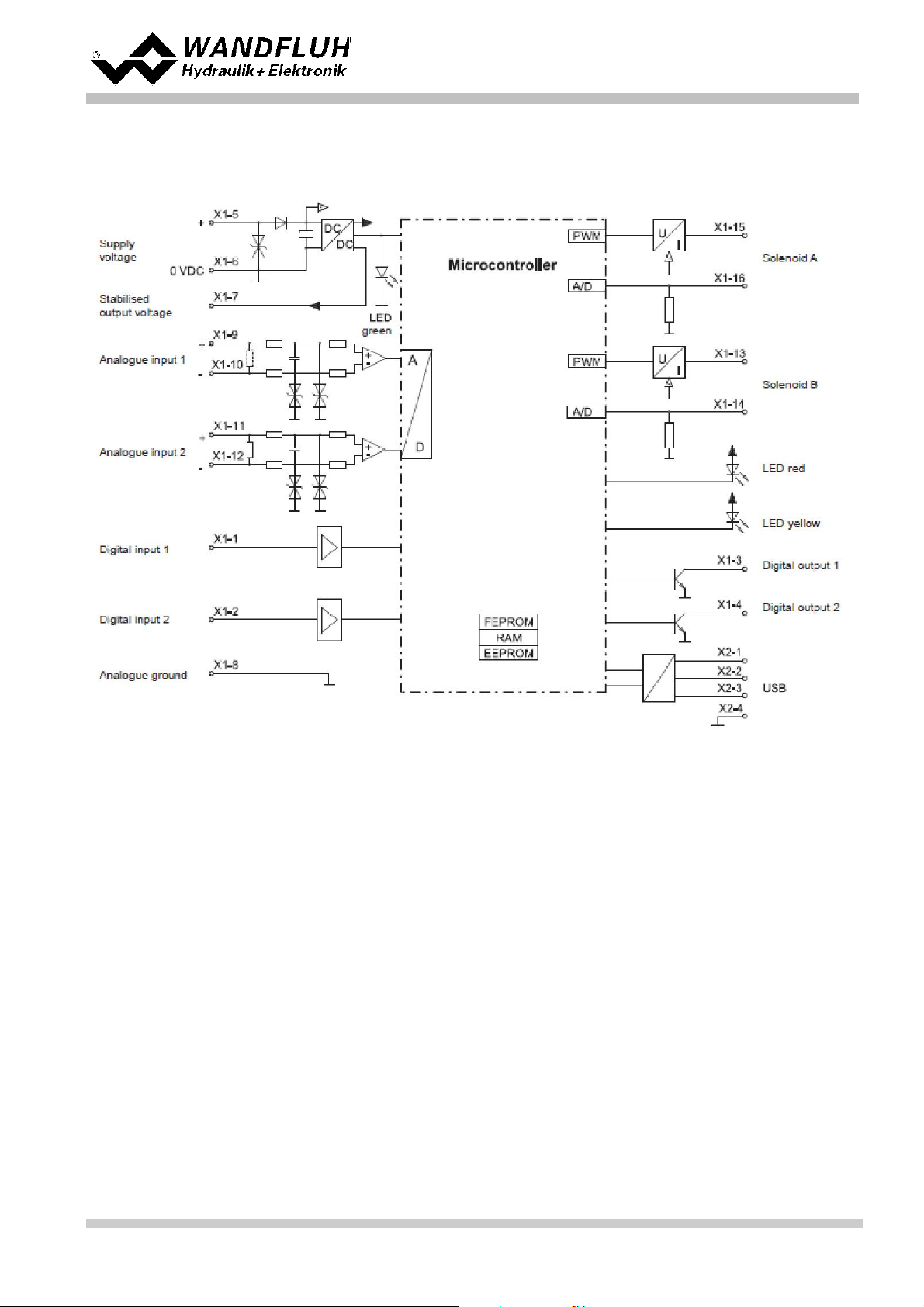
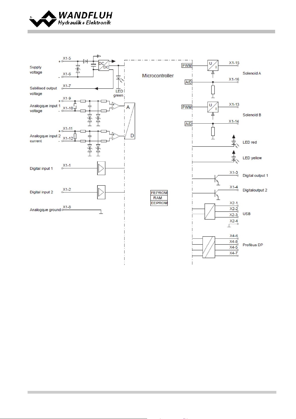
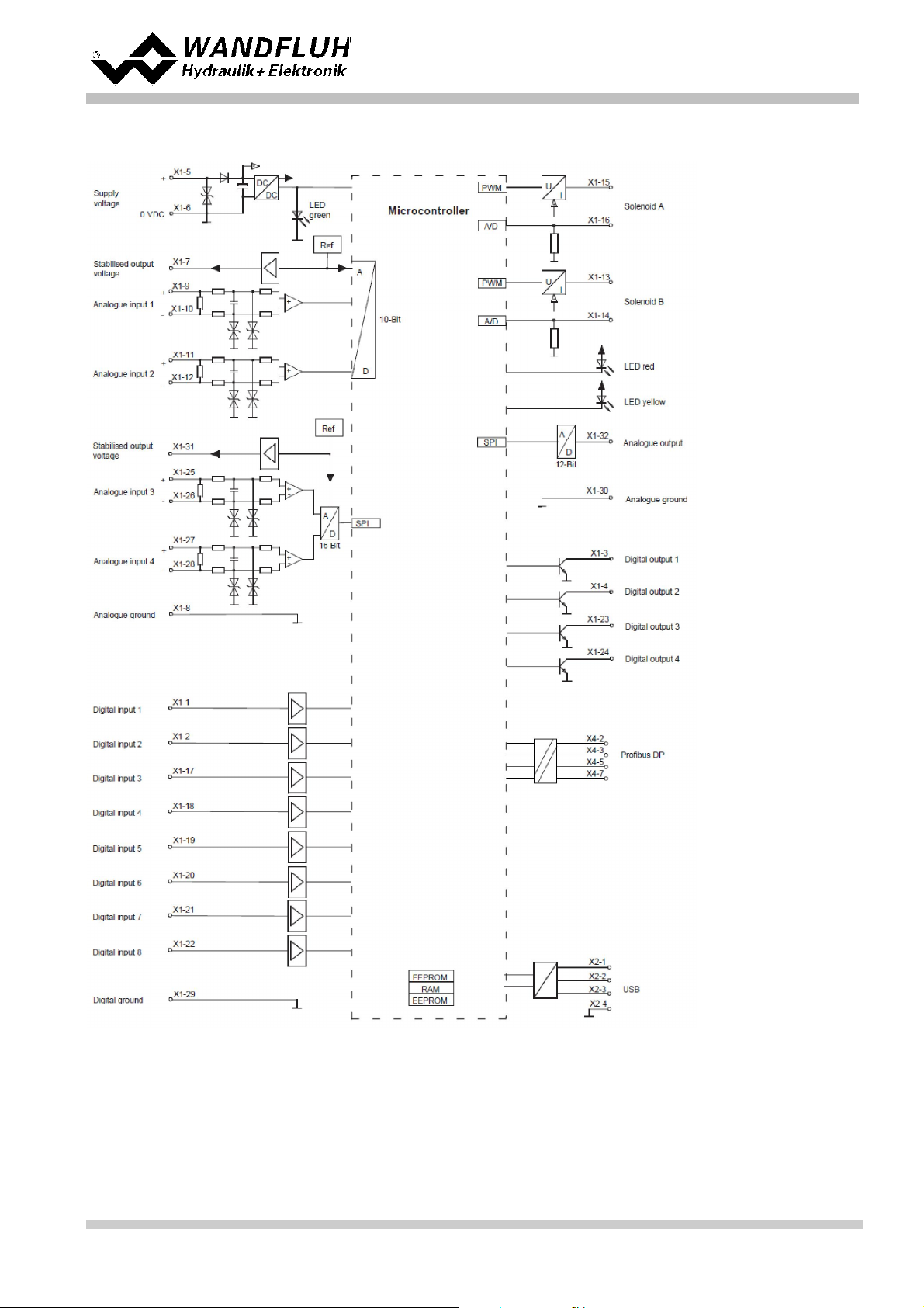
2.7 Block diagram
Basic version wi th ana log in te rfa ce
Operati n g Instructions to Amplifier Electronics SD7
Wandfluh AG
Postfach
CH-3714 Frutigen
Tel: +41 33 672 72 72
Fax: +41 33 672 72 12
Email: sales@wandfluh.com
Internet: www.wandfluh.com
Page 10
Edition 17 33
SD7_OperatingInstructions_
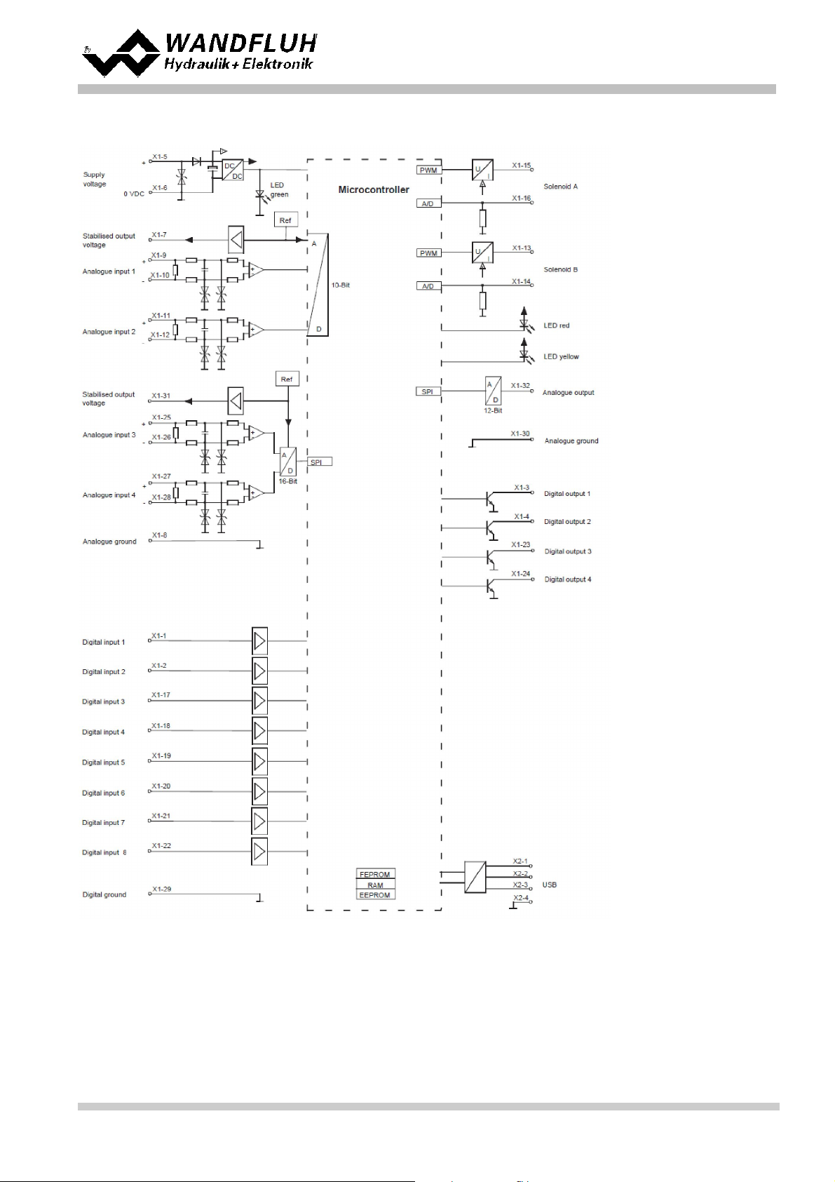
Page 11

Basic version wi th CANopen / J1939 interfa ce
Operati n g Instructions to Amplifier Electronics SD7
Wandfluh AG
Postfach
Tel: +41 33 672 72 72
Fax: +41 33 672 72 12
Email: sales@wandfluh.com
Internet: www.wandfluh.com
CH-3714 Frutigen
Page 11
Edition 17 33
SD7_OperatingInstructions_
Page 12
Basic version wi th Profi bus DP interfa ce
Operati n g Instructions to Amplifier Electronics SD7
Wandfluh AG
Postfach
Tel: +41 33 672 72 72
Fax: +41 33 672 72 12
Email: sales@wandfluh.com
Internet: www.wandfluh.com
CH-3714 Frutigen
Page 12
Edition 17 33
SD7_OperatingInstructions_
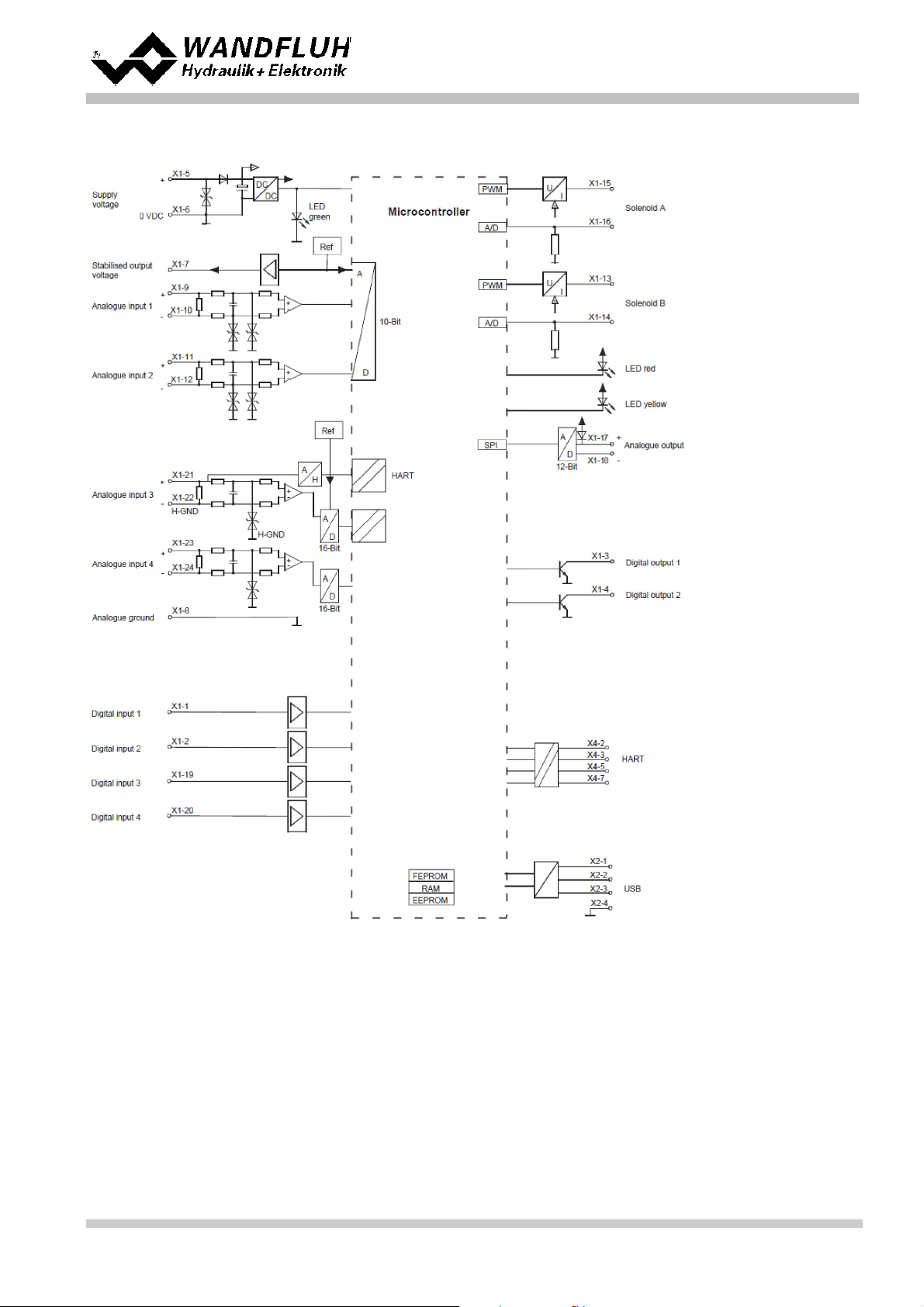
Page 13
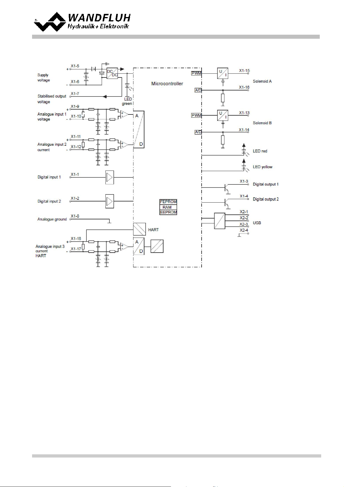
Basic version wi th HART interface
Operati n g Instructions to Amplifier Electronics SD7
Wandfluh AG
Postfach
Tel: +41 33 672 72 72
Fax: +41 33 672 72 12
Email: sales@wandfluh.com
Internet: www.wandfluh.com
CH-3714 Frutigen
Page 13
Edition 17 33
SD7_OperatingInstructions_
Page 14
Enhanced versi on wi th ana log in te rface
Operati n g Instructions to Amplifier Electronics SD7
Wandfluh AG
Postfach
Tel: +41 33 672 72 72
Fax: +41 33 672 72 12
Email: sales@wandfluh.com
Internet: www.wandfluh.com
CH-3714 Frutigen
Page 14
Edition 17 33
SD7_OperatingInstructions_
Page 15
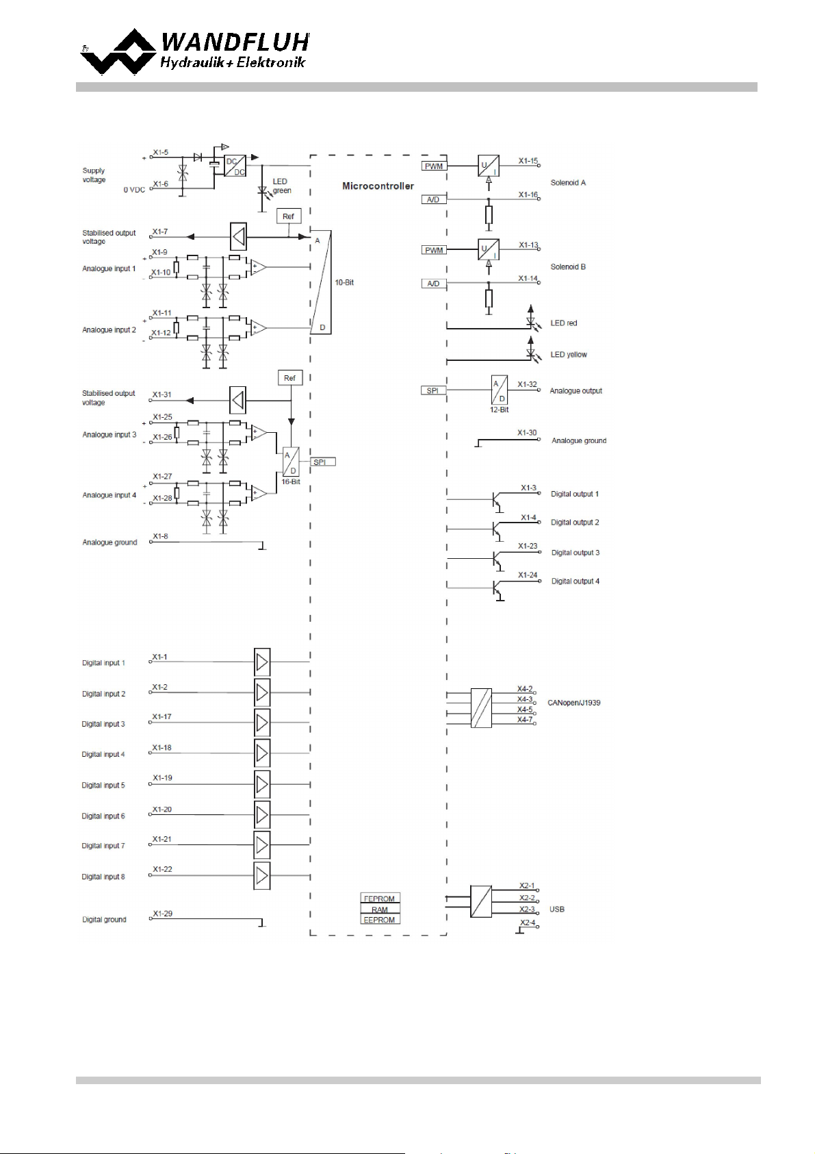
Enhanced versi on wi th CANopen / J1939 interfa ce
Operati n g Instructions to Amplifier Electronics SD7
Wandfluh AG
Postfach
Tel: +41 33 672 72 72
Fax: +41 33 672 72 12
Email: sales@wandfluh.com
Internet: www.wandfluh.com
CH-3714 Frutigen
Page 15
Edition 17 33
SD7_OperatingInstructions_
Page 16
Enhanced versi on wi th Profi bus DP interfa ce
Operati n g Instructions to Amplifier Electronics SD7
Wandfluh AG
Postfach
Tel: +41 33 672 72 72
Fax: +41 33 672 72 12
Email: sales@wandfluh.com
Internet: www.wandfluh.com
CH-3714 Frutigen
Page 16
Edition 17 33
SD7_OperatingInstructions_
Page 17
Enhanced versi on wi th HART interface
Operati n g Instructions to Amplifier Electronics SD7
Wandfluh AG
Postfach
Tel: +41 33 672 72 72
Fax: +41 33 672 72 12
Email: sales@wandfluh.com
Internet: www.wandfluh.com
CH-3714 Frutigen
Page 17
Edition 17 33
SD7_OperatingInstructions_
Page 18

Operati n g Instructions to Amplifier Electronics SD7
3 Safety rules
3.1 Installation / Commissi oning / Paramet eri sat i on
· These operating instructions have to be carefull y s tudied beforehand and the instructi ons are to be complied
with.
· Prior to the installati on, all power supply voltages and any other energy s ources have to be disc onnected.
· The inst allat ion/as sembly m ust only be carried out by specialist personnel with electrical k nowledge.
· Take into account precautionary measures concerning components on the module, which are subject to
damage as a result of electrost ati c dis charge.
· Wrong manipulat i ons by t he personnel cannot be prevented by the SD7-Electronics.
· Before the s witching on of the s upply voltage, the fuse protec tion, the c orrect wiring and t he c onform it y of the
power supply volt age with the permissible s upply voltage range have to be verified.
· The SD7-Electronics m onit ors t he working conditions within the el ectr onics and
within the i nstal l at i on. Uncontrolled movements or f orce changes caused by
unforeseen errors of the SD7-Electronics cannot be prevented in any case.
· Danger for persons has to be avoided by installi ng an emergency stop device which
cuts off the power to the system.
Wandfluh AG
Postfach
CH-3714 Frutigen
Tel: +41 33 672 72 72
Fax: +41 33 672 72 12
Email: sales@wandfluh.com
Internet: www.wandfluh.com
Page 18
Edition 17 33
SD7_OperatingInstructions_
Page 19
4 Construction and Function
- Enable channel
- Command s caling
- Command value fixed
- Ramp generator
- Monitoring
- Cont rol value
- Valve ty pe
- Solenoid driver
- Error evaluation
- Function
- Analog out put
(ref e r to section " E nable channel" )
(ref e r to section " Command sc aling" )
(ref e r to section " Command value fixed" )
(ref e r to section " Ramp generator" )
(ref e r to section "Monitoring" )
(ref e r to section " Control value" )
(ref e r to section " V alve type" )
(ref e r to section " S olenoid driver" )
(ref e r to section " E rror evaluation" )
(ref e r to section "Function" )
(ref e r to section " A nalog output" , only E nhanced version)
Operati n g Instructions to Amplifier Electronics SD7
Ref er to section "Bloc k diagram" .
10
4.1 Introduction
· All inputs and outputs have to be contacted through t he terminal screw block
· At the device front panel, there is a USB interfac e, t hrough which t he parameterisation and t he diagnostic s c an
be made by using the PC-Parameterisation software PA S O
· In the fac tory , the S D7-Elect ronics are adjusted with t he default values. The adjustment to the valves being
used, has to performed by t he user.
· Wandfluh c an c reate application specific parameters files in acc ordance to cust omer wish.
4.2 Description of the Function
T he SD7-Electronics has two channe ls.
Each channel has a command value input and one or two solenoid outputs. The adjustable parameters are
organiz ed in function blocks , which are displayed in PAS O as small boxes . The following settings can be made per
channel in these func t ion blocks:
52
52
58
59
60
61
63
64
68
69
70
Each channel is independent. Only the limits by the hardware are t o be c onsidered. For ex ample, if t he W andfluhElect ronic s has only two solenoid outputs . it's not possible to operat e two c hannels with each two s olenoids . In
this c as e the maximum is at t wo channels with one solenoid output per c hannel or one c hannels with t wo s olenoid
outputs per channel. The parameterisation software PASO automatically detects how many solenoids can be
select ed with the c urrent setti ngs.
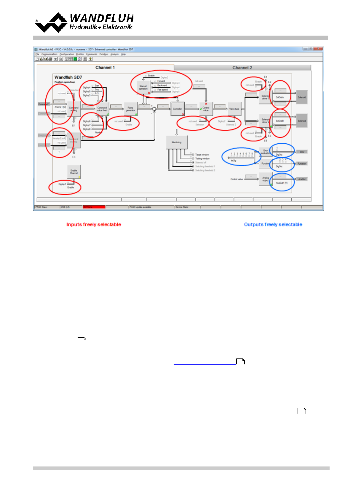
The ass i gnment of the analog and digital in- and outputs c an freel y be made by the user. Regarding inputs it is also
possible to adjust a multiple allocation. That means digital and analogue inputs can be allocated to multiple
channels (refe r to section " A s s ignment of t he inputs/ outputs " ). Digital in- and out puts which are set or reset by
softwar e (ref e r to section "Configuration - Digital E/A" ) will be displayed with blue text color in the main window.
Wandfluh AG
Postfach
CH-3714 Frutigen
Tel: +41 33 672 72 72
Fax: +41 33 672 72 12
76
46
Email: sales@wandfluh.com
Internet: www.wandfluh.com
Page 19
Edition 17 33
SD7_OperatingInstructions_
Page 20
Operati n g Instructions to Amplifier Electronics SD7
The comm and value can be a voltage-, a c urrent-, a frequency- or a PWM-s ignal. t he s ignals are individually
adjustable.
T he solenoid outputs includes a pulse-width-modulated current control with superimposed dither signal. These
outputs c an control either proportional or switching solenoids. The current measurement can be switc hed on or off.
The minimal and maximal solenoid currents or pulse widths can be adjusted separately. When using switching
solenoids a fully adjustable power reduction func tion is available.
Parameters are set by means of the parameterising s oftware P A S O. Changed parameters are stored in a nonvolatile memory in order to have t hem available after the Wandfluh-Electronics have been switched on again. The
paramet erising s oftware PAS O provides to s ave t he set t ings an values of the parameter in a file, which always
allows to do a download or an analysis.
Some function blocks are able to generate error messages. The function block "Error evaluation" (refer to sec tion
"Error evaluat ion" ) pick s up all error mes s ages. This function block manages the error handling of t he W andfluh-
68
Electronics.
The process data are displayed online (r efer to section " A naly sis_S how values" ). This helps in c as e of support
88
and diagnost ics.
4.3 Characteristic opti m i sat i on
The SD7 electronics are provided with a possibili ty to optimis e the c harac teristic “Preset value input – s olenoid
current out put”. The user is able to creat e a charac t eristi c (e.g. a l inearised characterist ic ) which matc hes his own
application. The characteristic optimis at ion c an be turned on or off (refer to “Parameters_Solenoid driver ”).
64
Wandfluh AG
Postfach
CH-3714 Frutigen
Tel: +41 33 672 72 72
Fax: +41 33 672 72 12
Email: sales@wandfluh.com
Internet: www.wandfluh.com
Page 20
Edition 17 33
SD7_OperatingInstructions_
Page 21
Operati n g Instructions to Amplifier Electronics SD7
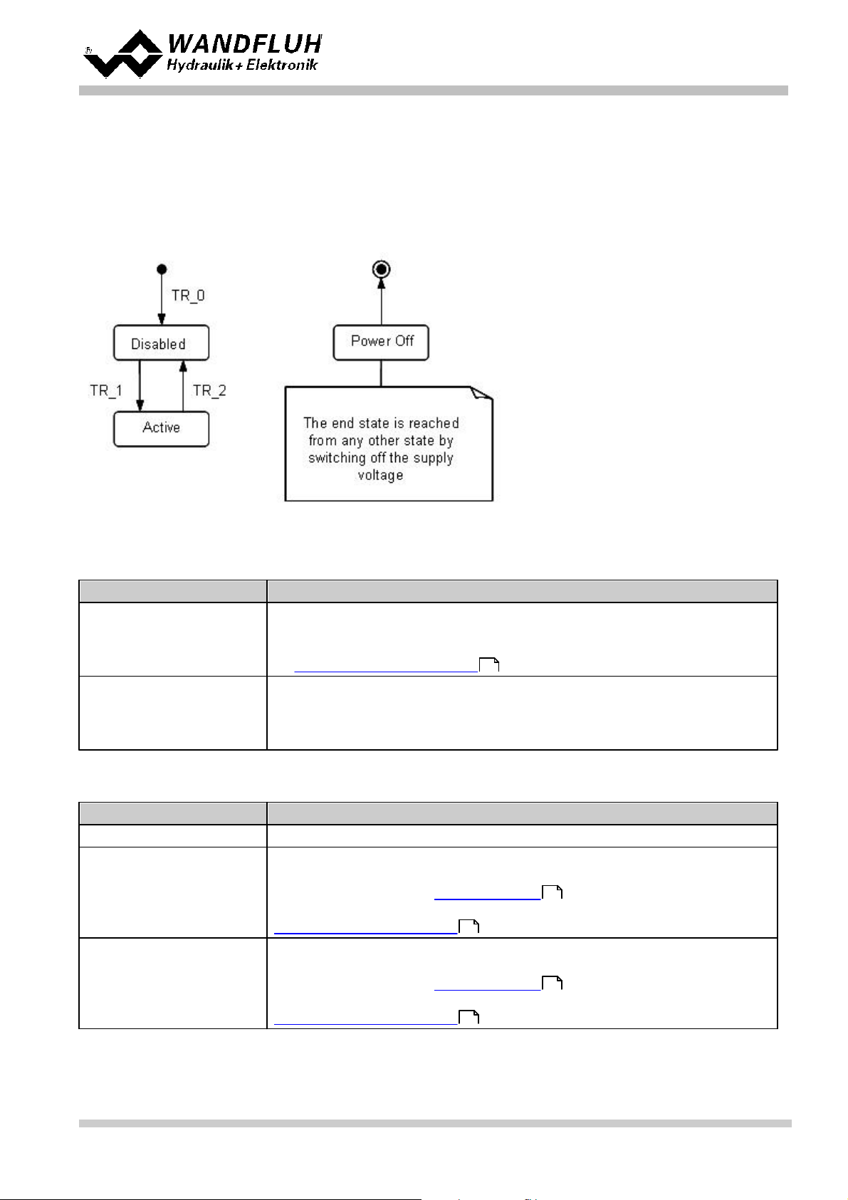
Status
Description
Disabled
· The assi gned channel of the W andfluh-El ec t ronics is disabled, no solenoid
current will be active
· In this status, with t he command "Operation mode" (refer to section
"Commands_Valve operati on" ) the operating mode can be set
Active
· The assi gned channel of the W andfluh-El ec t ronics is enabled
· The assi gned channel of the W andfluh-El ec t ronics c an be operat ed acc ording
to the selec t ed operating mode
· Changing the operating mode is not possible
Transition
Description
TR_0
Switc hing-on the supply voltage
TR_1
Enable
This is made in the operati ng mode "Local" t hrough the funct ion "E nable
Chan ne l" (refe r to section " E nable channel" ) and in the operating mode
"Remote PASO" through the parameter "Control mode" (refer to section
"Commands_Valve operati on" ).
TR_2
Disable
This is made in the operati ng mode "Local" t hrough the funct ion "E nable
Chan ne l" (refe r to section " E nable channel" ) and in the operating mode
"Remote PASO" through the parameter "Control mode" (refer to section
"Commands_Valve operati on" ).
4.4 State machine
In t he following, with the help of a status diagram it is described, how t he start-up of the W andfluh-Electronics
takes plac e and which status es are reached when and how.
Impo rta nt: Each chan nel has its ow n state m achine. Th e state s of each channel can be set se parately.
The following t able describes t he poss ible s t at us es and what is done in these st atus es :
82
The following t able describes t he transit ions from one status t o t he next one:
52
82
82
Wandfluh AG
Postfach
CH-3714 Frutigen
Tel: +41 33 672 72 72
Fax: +41 33 672 72 12
Email: sales@wandfluh.com
Internet: www.wandfluh.com
52
Page 21
Edition 17 33
SD7_OperatingInstructions_
Page 22
Operati n g Instructions to Amplifier Electronics SD7
Operating m o de
Acti vating wi th
Description
Local
Menu point " Commands_Local Operat ing"
Operat ing via analogue and digital inputs on
the Wandfluh-El ec t ronics
Remote PASO
Menu point " Commands_PAS O Operating
Operat ing direct with t he PA S O
SD7 type
Analog ue i nput 1
Analog ue i nput 2
Analog ue i nput 3
(only Enhanced
Version)
Analog ue i nput 4
(only Enhanced
Version)
SD7XXXD
X0-AX
Voltage
Current----
SD7XXXD
X1-AX
Voltage
Voltage----
SD7XXXD
X2-AX
Current
Current
SD7XXXD
X4-BX
Voltage
Current
Voltage
Current
SD7XXXD
X5-BX
Voltage
Voltage
Voltage
Voltage
SD7XXXD
X6-BX
Current
Current
Current
Current
4.5 Operati ng mode
The Wandfluh-El ect ronics have 2 operating modes. The following table describes, what c an be done in t he different
operati ng modes and how t hey c an be acti vat ed:
The current operating mode is displayed in the status line (refer t o section "Starting of P A S O" ).
108
4.6 Analogue inputs
· The applied analogue signal is digit ised on analogue inputs 1 and 2 in the 10-Bit A / D c onverter and on analogue
3 and 4 (only E nhanced version) in the 16-Bi t A /D converter.
Attention: By t he input range 4 . . . 20mA, t he resolution is < 10-Bit resp. 16-Bit!!
· Differen tial i np uts
All analogue inputs are different i al inputs . Differential inputs are used if the ground potential of t he ext ernal
command value generator does not agree with the ground on the W andfluh-El ec t ronics . The differenti al inputs are
not galvanically s eparated; they are made for ground potential differences up to 1.5V between the – (minus)
connection of the different ial input and the 0V-ground of the Wandfluh-Elect ronics . If the different ial input is
intended to use like an analogue input against ground, t he - (minus) connection of the differenti al input mus t be
connected to the ground of the Wandfluh-Elec tronics. In this c as e please att end that t he solenoid current can
cause a voltage drop between the Wandfluh-Elec t ronics and the power supply. It is recommended to connect the
- (minus) connection as near as possible to the power supply.
· Filtering
Each analog input can be individuall y filtered (refer to "Configuration_Filter for analog i nputs "). Thereby analog
noise (e.g. voltage peaks) are attenuat ed. The filtering is done wit h t he function "exponential smoothing", where
the speed / response time of the fil t er can be determined wit h t he parameter "smoothing factor". A high value at
the smoothing factor results in a high degree of filtering, but a long response t im e, which will delayed the reading
of the analog input. A small value at t he sm oothing factor results in a sm all degree of filtering, but a fast
response time. So t he "smoothing factor" must be selec t ed as compromise between high degree of filtering and
fast response time.
78
Wandfluh AG
Postfach
CH-3714 Frutigen
Tel: +41 33 672 72 72
Fax: +41 33 672 72 12
Email: sales@wandfluh.com
Internet: www.wandfluh.com
Page 22
Edition 17 33
SD7_OperatingInstructions_
Page 23

Operati n g Instructions to Amplifier Electronics SD7
SD7XXXD
X7-BX
Voltage
Voltage
Current
Current
SD7XXXD
X8-BX
Current
Current
Voltage
Voltage
The assignment of the analog i nputs to the corresponding channel is free to choose (refer to section "Assignment
of the inputs/outputs " ).
46
If a potentiometer is connected, a value of 1k Ohm is recommended.
Wandfluh AG
Postfach
CH-3714 Frutigen
Tel: +41 33 672 72 72
Fax: +41 33 672 72 12
Email: sales@wandfluh.com
Internet: www.wandfluh.com
Page 23
Edition 17 33
SD7_OperatingInstructions_
Page 24
Operati n g Instructions to Amplifier Electronics SD7
Attention:
Until a cablebreak will be detected, a time delay of about 100ms will pass. During this time, the
cy li nder can make unintentional movements or unintent i onal force changes
4.7 Cablebreak detecti on
The c ommand value input c an be det ected for a cablebreak (only if Signal ty pe = V oltage, Current, Frequency or
PWM). Therefore, a lower and an upper cablebreak limit c an be adjusted in the box Signal s c aling .A cablebreak
is detec t ed, if the input si gnal is smaller than the lower c ablebreak limit or higher than the upper c ablebreak limi t .
If an cablebreak is detected, the internal error "E-1" (for command value) resp. " E-6" (for feedback value) i s act ive
(refer to section "Error evaluat i on" ).
68
The following c onditions had to be performed:
· The parameter "Signal type" m ust be on "Voltage", "Current" , " F requency" or "PWM" (refer to section Signal
scaling )
· The parameter "Cablebreak" must be on "On" (refer to section S i gnal sc aling )
52
52
· The parameters " Lower cablebreak limt " and "Upper cablebreak limit" mus t be adjusted (refer t o section Signal
scaling )
· An acti on must be assigned to the error "E-1" (refer t o section "E rror evaluat ion" )
52
68
52
Wandfluh AG
Postfach
CH-3714 Frutigen
Tel: +41 33 672 72 72
Fax: +41 33 672 72 12
Email: sales@wandfluh.com
Internet: www.wandfluh.com
Page 24
Edition 17 33
SD7_OperatingInstructions_
Page 25
Operati n g Instructions to Amplifier Electronics SD7
4.8 Digital i nputs
The functin of the digital inputs and the assignment to the corresponding c hannel is free to choose (refer to secti on
"Assignment of the inputs/outputs " ).
46
4.9 Outputs
· Proportiona l solenoi d outputs A and B
T he solenoid outputs have a current output pulse-width-modulated at 1000Hz with s uperimposed dither. The
current measurem ent c an be switched on or off.
The assignment t o the corresponding channel is free to choose (refer to section "Assi gnment of the
inputs/outputs" ).
· Digital ou tputs
The SD7-Electronics has two (Basic version) resp. four (Enhanced version) digit al outputs . The function of the
digital outputs and the as signment to the correspondi ng channel is free to choose (refer to section "Assignment
of the inputs/outputs " ) or c an be s et fixed on 0 or 1 with the PASO (refer to sect i on "Configuration_Digital
76
I/O" ).
46
46
· Analog output (only Enhanced ve rsion)
The analog out put can be assigned to the following signals via the PASO SD7 (depending on the control mode,
different signals are available):
- command value for the solenoid driver
- scaled comm and value
- scaled feedback value (only Controll er version and with clos ed loop control modes)
- scaled control deviation (only Controll er version and with closed loop control modes)
The si gnal at the analog output c an be used for driving a valve with integrated electronics which has a volt age
interfac e. The out put l evel c an be adjusted (refer to section "Analog output" ).
70
4.10 Internal si gnals
Internal s ignals can be selected inst ead of digital inputs or outputs. They are not guided to the outside, t hey are
processed only internally.
This allows e.g. t o li nk a digital output t o a digital input without an external connection.
Wandfluh AG
Postfach
CH-3714 Frutigen
Tel: +41 33 672 72 72
Fax: +41 33 672 72 12
Email: sales@wandfluh.com
Internet: www.wandfluh.com
Page 25
Edition 17 33
SD7_OperatingInstructions_
Page 26
Operati n g Instructions to Amplifier Electronics SD7
Valve ty pe = S t andard 2-s olenoid
Valve ty pe = 4/3-W ege 1-solenoid
1
Valve ty pe = S t andard 2-s olenoid
Valve ty pe = 4/3-W ege 1-solenoid
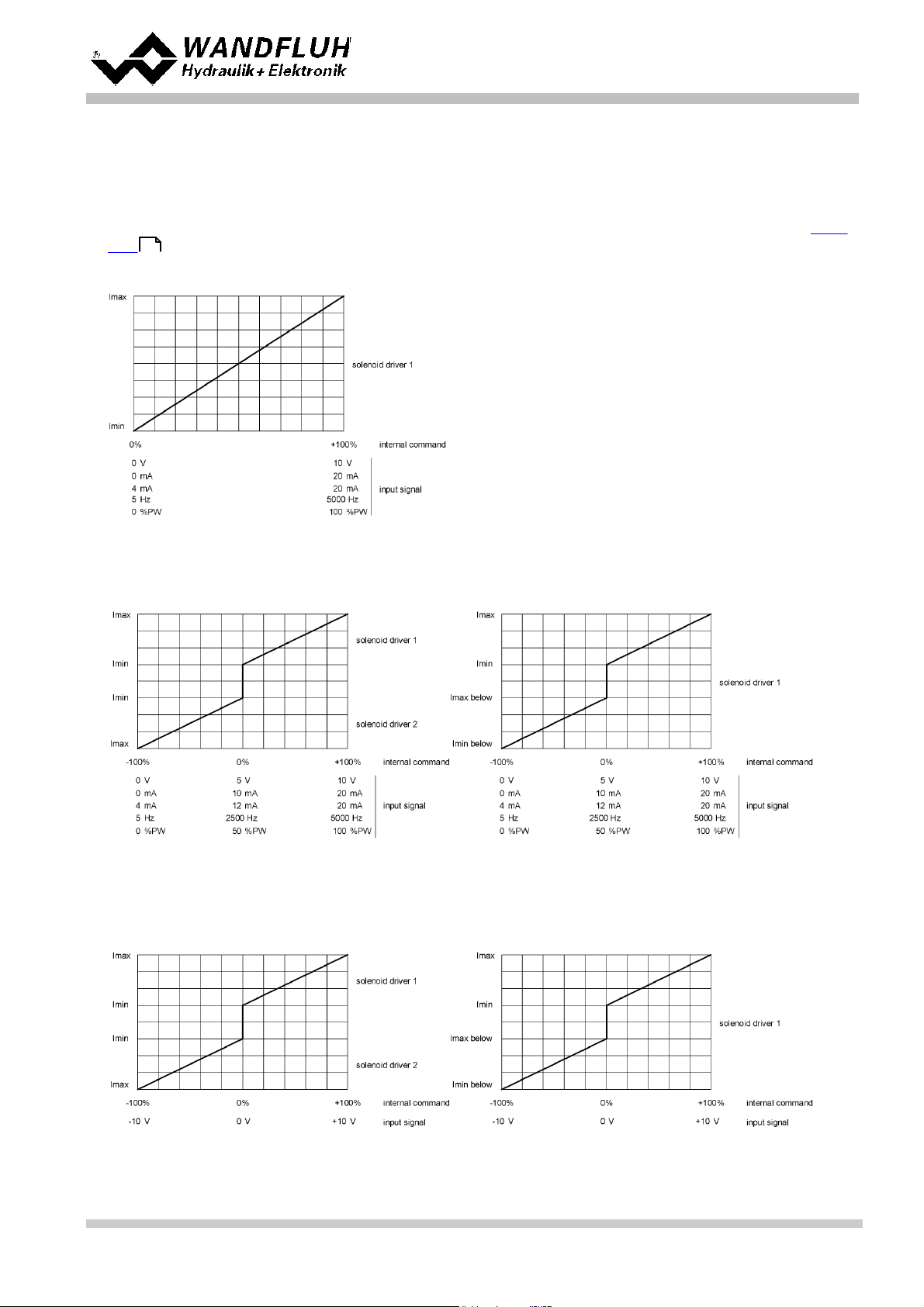
4.11 Mode of operation
The mode of operation can be set independently for each channel. The following 4 modes of operation are possible:
· Mode o f opera tion "Comm and un i pola r (1-sol)" (Mode of opera ti on 1)
This Mode of operation is only possible, if the valve type is s et t o " S tandard 2-solenoid" (refer to section "Valve
63
type ").
With an input signal 0 ... 100% an internal command from 0 .. . 100% is generated.
· Mode o f opera tion "Comm and un i pola r (2-sol)" (Mode of opera ti on 2)
With an input signal 0 ... 100% an internal command from -100 ... + 100% is generat ed.
· Mode o f opera tion "Comm and biipola r (2-sol)" (Mode of opera tio n 3)
With an input signal -100 . . . 100% an internal command from -100 ... +100% is generated.
Wandfluh AG
Postfach
CH-3714 Frutigen
Tel: +41 33 672 72 72
Fax: +41 33 672 72 12
Email: sales@wandfluh.com
Internet: www.wandfluh.com
Page 26
Edition 17 33
SD7_OperatingInstructions_
Page 27

Operati n g Instructions to Amplifier Electronics SD7
Wandfluh AG
Postfach
Tel: +41 33 672 72 72
Fax: +41 33 672 72 12
Email: sales@wandfluh.com
Internet: www.wandfluh.com
CH-3714 Frutigen
Page 27
Edition 17 33
SD7_OperatingInstructions_
Page 28
Operati n g Instructions to Amplifier Electronics SD7
Valve ty pe = S t andard 2-s olenoid
Valve ty pe = 4/3-W ege 1-solenoid
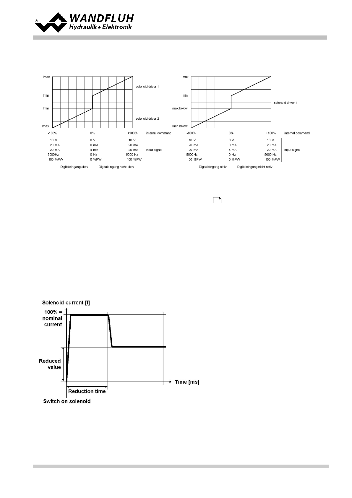
· Mode o f opera tion "Comm and un pol ar (2-sol mit DigI np)" (Mode o f opera tion 4)
With an input signal 0 ... + 100% an internal command from 0 ... + 100% (digital input not act i ve) resp. 0 ... 100% (digital input ac t ive) is generat ed.
The selection of the mode of operation is made in the box "V alve t ype"
63
4.12 Power reduction
The power reduction c an be switc hed on with solenoid type "Switching solenoid without current measuring".
Once the solenoid has switc h on, t he full solenoid current (= nominal current of the solenoid) pas ses t hrough during
the adjusted time (Parameter "Reduc tion time"). Thereafter, the current is limi t ed to t he reduced value (Parameter
"Reduced value" ). The reduced value refers to t he nominal current of t he solenoid (100% = nominal c urrent, 50% =
half nominal c urrent).
Wandfluh AG
Postfach
CH-3714 Frutigen
Tel: +41 33 672 72 72
Fax: +41 33 672 72 12
Email: sales@wandfluh.com
Internet: www.wandfluh.com
Page 28
Edition 17 33
SD7_OperatingInstructions_
Page 29

Operati n g Instructions to Amplifier Electronics SD7
Wandfluh AG
Postfach
Tel: +41 33 672 72 72
Fax: +41 33 672 72 12
Email: sales@wandfluh.com
Internet: www.wandfluh.com
CH-3714 Frutigen
Page 29
Edition 17 33
SD7_OperatingInstructions_
Page 30
Operati n g Instructions to Amplifier Electronics SD7
5 Operating and indicating elements
5.1 General
· All inputs and outputs have to be contacted through t he terminal screw blocks
· On the front panel of the electronic housing, there is a USB int erface, through which t he parameterisation and t he
diagnos tic s c an be made by using the PC-Parameterisation software PASO SD7
· Additionally t he front panel from t he Bas ic amplfier provides an optionally s im ple manual operation t erminal
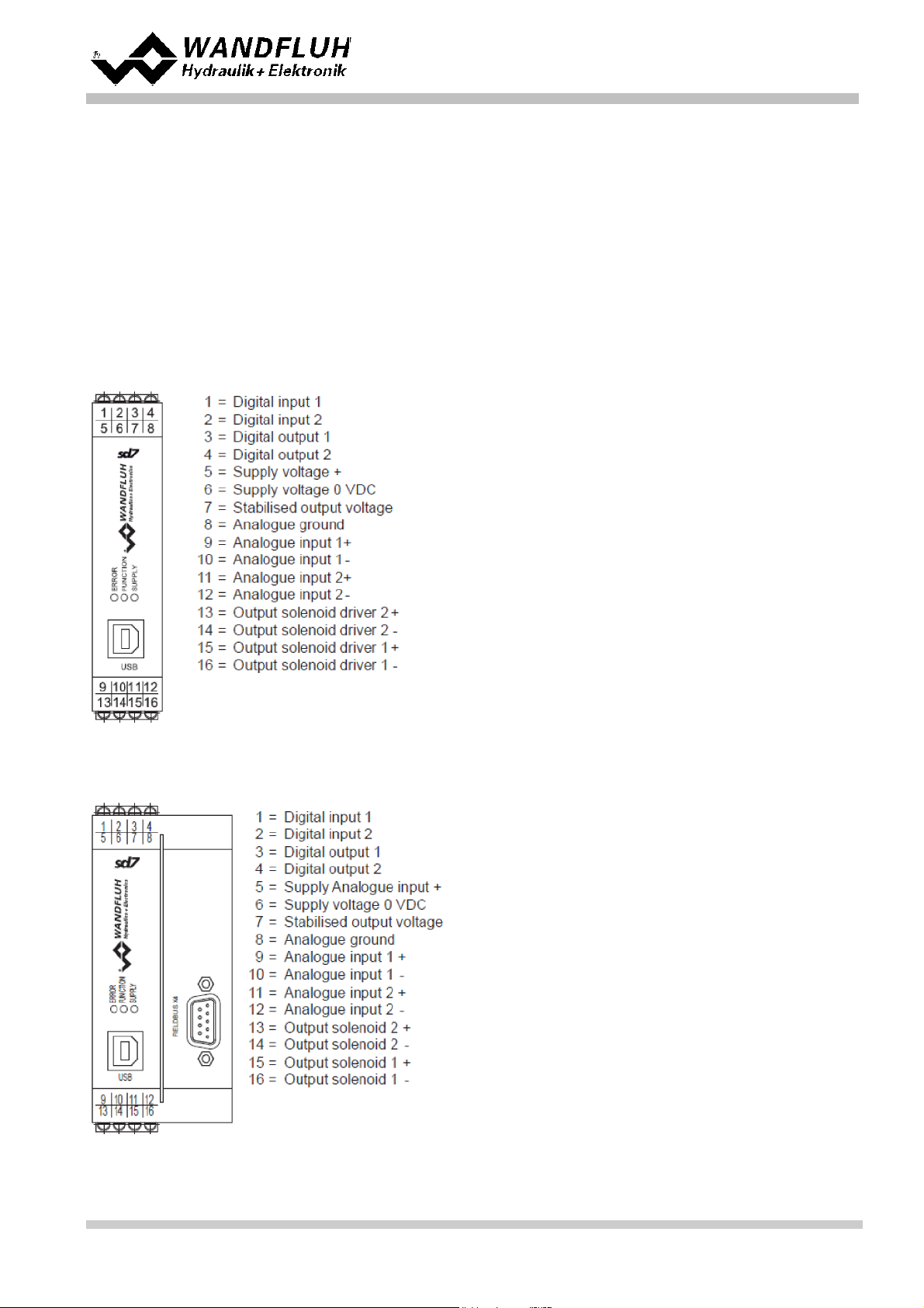
5.2 Screw terminator view
Basic ampl i fi er with analog interface
Basic ampl i fi er with CANopen/J1939 or Profibus DP i nterface
Wandfluh AG
Postfach
CH-3714 Frutigen
Tel: +41 33 672 72 72
Fax: +41 33 672 72 12
Email: sales@wandfluh.com
Internet: www.wandfluh.com
Page 30
Edition 17 33
SD7_OperatingInstructions_
Page 31

Basic ampl i fi er with HART interface
Operati n g Instructions to Amplifier Electronics SD7
Enhanced am pl i fi er with analog i nterface
Wandfluh AG
Postfach
Tel: +41 33 672 72 72
Fax: +41 33 672 72 12
Email: sales@wandfluh.com
Internet: www.wandfluh.com
CH-3714 Frutigen
Page 31
Edition 17 33
SD7_OperatingInstructions_
Page 32

Operati n g Instructions to Amplifier Electronics SD7
Enhanced am pl i fi er with CANopen/J1939 or Profibus DP i nterface
Wandfluh AG
Postfach
Tel: +41 33 672 72 72
Fax: +41 33 672 72 12
Email: sales@wandfluh.com
Internet: www.wandfluh.com
CH-3714 Frutigen
Page 32
Edition 17 33
SD7_OperatingInstructions_
Page 33

Enhanced am pl i fi er with HART interfa ce
Operati n g Instructions to Amplifier Electronics SD7
Wandfluh AG
Postfach
Tel: +41 33 672 72 72
Fax: +41 33 672 72 12
Email: sales@wandfluh.com
Internet: www.wandfluh.com
CH-3714 Frutigen
Page 33
Edition 17 33
SD7_OperatingInstructions_
Page 34
Operati n g Instructions to Amplifier Electronics SD7
front view
1: ERROR-LED red
2: FUNCTION-LED yellow
3: SUPPLY -LED green
4: USB int erface
front view
1: ERROR-LED red
2: FUNCTION-LED yellow
3: SUPPLY -LED green
4: USB int erface
7: Rotary switch
8: VA LUE-LED yellow
9: UP key
10: DOWN key
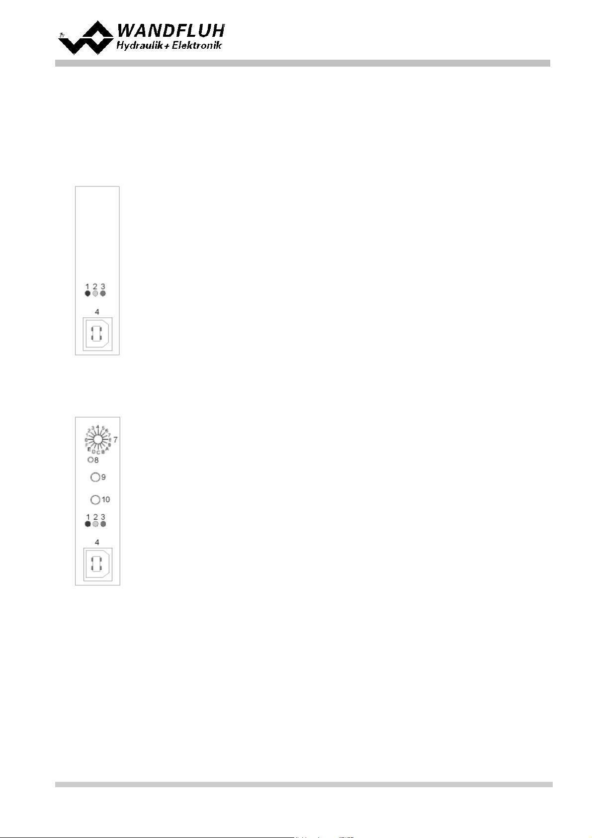
5.3 Control el ements
5.3.1 General
The front panel of the SD7-electronics include in addition to t he USB i nterfac e t hree LED's, which provide the us er
with information on the operat ion of the electronics.
Front panel B as ic-amplifier with analognterface:
Front panel B as ic-amplifier with analoginterface and manual operation terminal:
Front panel B as ic-amplifier with CANopen/J1939 or Profibus DP i nterface:
Wandfluh AG
Postfach
CH-3714 Frutigen
Tel: +41 33 672 72 72
Fax: +41 33 672 72 12
Email: sales@wandfluh.com
Internet: www.wandfluh.com
Page 34
Edition 17 33
SD7_OperatingInstructions_
Page 35

front view
1: ERROR-LED red
2: FUNCTION-LED yellow
3: SUPPLY -LED green
4: USB int erface
6: Fieldbus interface (9-pol D-Sub)
Front panel B as ic-amplifier with HART interface:
front view
1: ERROR-LED red
2: FUNCTION-LED yellow
3: SUPPLY -LED green
4: USB int erface
front view
1: ERROR-LED red
2: FUNCTION-LED yellow
3: SUPPLY -LED green
4: USB int erface
Operati n g Instructions to Amplifier Electronics SD7
Front panel E nhanced-amplifier with analog interface:
Front panel E nhanced-amplifier with CANopen/ J1939 or P rofibus DP interface:
Wandfluh AG
Postfach
CH-3714 Frutigen
Tel: +41 33 672 72 72
Fax: +41 33 672 72 12
Email: sales@wandfluh.com
Internet: www.wandfluh.com
Page 35
Edition 17 33
SD7_OperatingInstructions_
Page 36

front view
1: ERROR-LED red
2: FUNCTION-LED yellow
3: SUPPLY -LED green
4: USB int erface
6: Fieldbus interface (9-pol D-Sub)
Front panel E nhanced-amplifier with HART int erface:
front view
1: ERROR-LED red
2: FUNCTION-LED yellow
3: SUPPLY -LED green
4: USB int erface
Operati n g Instructions to Amplifier Electronics SD7
Wandfluh AG
Postfach
CH-3714 Frutigen
Tel: +41 33 672 72 72
Fax: +41 33 672 72 12
Email: sales@wandfluh.com
Internet: www.wandfluh.com
Page 36
Edition 17 33
SD7_OperatingInstructions_
Page 37

Operati n g Instructions to Amplifier Electronics SD7
Rotary se le ctor
Position
1-Solenoid
2-Solenoid
0
No parameter select ed
No parameter select ed
1
Imin A
Imin A
2
Imax A
Imax A3-
Imin B4-
Imax B
5
Dither frequency
Dither frequency
6
Dither level
Dither level
7
Ramp A up
Ramp A up
8
Ramp A down
Ramp A down
9
-
Ramp B upA-
Ramp B down
B
Max Interface
Max Interface
C
Min Interface
Min Interface
D
Signal type
Signal type
E
Dead band
Dead bandF-
Mode of operation
5.3.2 Rotary se le ctor
By means of the rotary s elec tor the parameter is s elected, which has t o be adjusted. The parameters "Sc al ing
command value", "Offset", "Signal type" and "Mode of operation" are adjusable i n the SD7-state "Disabled" only
(ref e r to section " S tate machine" ).
21
It is possible to add other param et ers to t he respective rotary s elec tor positions. Pleas e refer to section
Configuration_Manual operat i on parameters for more details .
78
Wandfluh AG
Postfach
CH-3714 Frutigen
Tel: +41 33 672 72 72
Fax: +41 33 672 72 12
Email: sales@wandfluh.com
Internet: www.wandfluh.com
Page 37
Edition 17 33
SD7_OperatingInstructions_
Page 38

Operati n g Instructions to Amplifier Electronics SD7
5.3.3 VALUE-LED (yell ow)
The VA LUE-LED displays the current value of the parameter which is selected by flashing code.
Example:
Follow this s t eps to adjust dither level to 140 mA.
Wandfluh AG
Postfach
CH-3714 Frutigen
Tel: +41 33 672 72 72
Fax: +41 33 672 72 12
Email: sales@wandfluh.com
Internet: www.wandfluh.com
Page 38
Edition 17 33
SD7_OperatingInstructions_
Page 39

Operati n g Instructions to Amplifier Electronics SD7
1. Select rotary s elec t or positi on 6 for " diht er level"
1. Find the passage from 3x flashing to 4x flashing by pressing the UP / DOWN Key s
1. The first value of the range 4x flashing is 121mA
1. The interval per keypress is 3.8 mA (24V-version). Thus t he UP-Key has t o be pressed 5 times t o reach 140
mA s tarting from 121 mA.
® 121 mA + 5 x 3.8 mA = 140 mA
View of the USB-interfac e:
1
2
3 4
X2-1 = VBUS
X2-2 = DX2-3 = D+
X2-4 = GND
5.3.4 UP- / DOWN-Key
By t he UP- / DOWN Key t he selec t ed parameter can be adjust ed. A t each key stroke t he parameter is changed by
one step. If a key is pressed during a period longer as 1 s, the paramet er will be c hanged in fast c y c le, as l ong as
the key is pressed.
5.3.5 ERROR-LED (red)
The ERROR-LED displays, when an error is detected (refer to section "The system does not work" ).
100
5.3.6 FUNCTI ON-LED (ye l l ow)
The F UNCTION-LED is lighting as soon as a selected Func tion (refer to s ection "Function ") is ac tive. Only
69
func tions which are assigned to a DigOut or a IntSig will be displayed.
5.3.7 SUPPLY-LED (green)
The SUPP LY-LED is li ghting, when the SD7-elec t ronics are supplied.
5.3.8 USB-interface
The USB-interface is placed under the transparent plastic screw cap. It allows the parameterisation and the
analysis of the SD7-el ectronics by PASO s oftware. The c onnection t o t he PC is realised by st andard USB-cables
(USB Type A connector PC-side, USB Type B connector SD7-side).
Connector USB Type B
Hint: The USB -c able is not i nc luded.
Wandfluh AG
Postfach
CH-3714 Frutigen
Tel: +41 33 672 72 72
Fax: +41 33 672 72 12
Email: sales@wandfluh.com
Internet: www.wandfluh.com
SD7_OperatingInstructions_
Page 39
Edition 17 33
Page 40

6 Commissioning
Operati n g Instructions to Amplifier Electronics SD7
Pleas e refer to section "Sa fety rule s" .
18
6.1 Connection instructi ons
The contact assignment of the following description refers to section "Operating and Indicating elements" and to
section "Connection examples" .
42
For an installation / conne ction appropri ate for EMC, the following points abs olutely have to be observed:
· The top-hat rail has to be connected with the earthing wi t h an as s hort as pos s i ble c onductor with a strand
cross sect ion >= 1.5 mm2.
· Solenoid- and signal cables mus t not be laid parallel t o high voltage cables.
6.1.1 Supply vol ta g e
· For the di mensi oning of the power supply, t he maxi mum current demand of t he s olenoids has to be increased
by the no load current from the SD7-Electronics (refer to section "Elec t ric al specifications" ).
7
· The limit values of the supply volt age and its residual ripple indispensably have to be complied with (refer to
section "E lec t ric al specifications" ).
7
· The SD7-Electronics have to be protected with a slow acting fuse
6.1.2 Digital inp uts and outputs
· The digital inputs are active-high and not galvanically separated
· For activat i on, t hey have to be connected to a voltage between 6 . .. 30VDC (e.g. power s upply)
30
· The digital outputs are "Lowside Switch" outputs (open collector)
Wandfluh AG
Postfach
CH-3714 Frutigen
Tel: +41 33 672 72 72
Fax: +41 33 672 72 12
Email: sales@wandfluh.com
Internet: www.wandfluh.com
Page 40
Edition 17 33
SD7_OperatingInstructions_
Page 41

Operati n g Instructions to Amplifier Electronics SD7
6.1.3 Analog ue i nputs
· The basic amplifier has two analog inputs with 10 Bit resolution (Basic version) resp. four analog input s with 16Bit resp. 16-Bit resolution (Enhanced version).
· All inputs are differential inputs
· If a potentiometer is c onnected, a value of 1kOhm is recommended
6.1.4 Solenoi d outputs
· The solenoid outputs are able t o meas ure the solenoid current. This is neces sary for controlling the solenoid
current if the parameter "Solenoid type" is set to "Proportional solenoid wit h c urrent measurement " (refer to
section "V alve t ype" ). In this case, t he negative pole of the s olenoid has to be connected to the appropriate
negative pole of the solenoid output (for example "Output solenoid A -" , refer to section "Connector view" ).
63
30
· If the parameter "Solenoid type" is s et to "Proportional solenoid wit hout c urrent measurement " or "Switching
solenoid without current measurement" a current measurement is not neces sary (refer to section "Valve
63
type" ). The negative pole of the solenoid can be connected directly to t he 0VDC of t he Supply V olt age
(Solenoid Out puts ).
Wandfluh AG
Postfach
CH-3714 Frutigen
Tel: +41 33 672 72 72
Fax: +41 33 672 72 12
Email: sales@wandfluh.com
Internet: www.wandfluh.com
Page 41
Edition 17 33
SD7_OperatingInstructions_
Page 42

6.2 Connection examples
Operati n g Instructions to Amplifier Electronics SD7
The contact assignment of the following description refers to section "Operating and Indicating elements" .
30
6.2.1 Basic Am p l i fier
Mode of ope ration "Com mand uni polar (2-sol)" or "Comma nd unipola r (2-sol wi th DigInp)" - 1 cha nnel
active
Mode o f opera tion "Comm and u ni pola r (1-sol)" - 2 channel s active
Wandfluh AG
Postfach
CH-3714 Frutigen
Tel: +41 33 672 72 72
Fax: +41 33 672 72 12
Email: sales@wandfluh.com
Internet: www.wandfluh.com
Page 42
Edition 17 33
SD7_OperatingInstructions_
Page 43

Operati n g Instructions to Amplifier Electronics SD7
6.2.2 Enhanced Amplifier
Mode of ope ration "Com mand uni polar (2-sol)" or "Comma nd unipola r (2-sol wi th DigInp)" - 1 cha nnel
active
6.2.3 Alternative connections
Command va lue 0 . .. 10 VDC or -10 ... + 10VDC via external P L C without ga l vani c separation
Wandfluh AG
Postfach
CH-3714 Frutigen
Tel: +41 33 672 72 72
Fax: +41 33 672 72 12
Email: sales@wandfluh.com
Internet: www.wandfluh.com
Page 43
Edition 17 33
SD7_OperatingInstructions_
Page 44

Operati n g Instructions to Amplifier Electronics SD7
Command va lue 0 . .. 10 VDC or -10 ... + 10VDC via external P L C with galvanic sepa ration
Command va lue 0 . .. 20 mA resp. 4 .. . 20 m A via ex te rnal PLC
Command va lue -10 .. . +10 VDC via potentiomete r wi th external supply
Wandfluh AG
Postfach
Tel: +41 33 672 72 72
Fax: +41 33 672 72 12
Email: sales@wandfluh.com
Internet: www.wandfluh.com
CH-3714 Frutigen
Page 44
Edition 17 33
SD7_OperatingInstructions_
Page 45

Control of digita l i npu ts vi a external P LC
Eval uation of di gital outputs vi a ex terna l P LC
Operati n g Instructions to Amplifier Electronics SD7
Wandfluh AG
Postfach
Tel: +41 33 672 72 72
Fax: +41 33 672 72 12
Email: sales@wandfluh.com
Internet: www.wandfluh.com
CH-3714 Frutigen
Page 45
Edition 17 33
SD7_OperatingInstructions_
Page 46

7 Settings
Digital inputs
DigInp1
DigInp2
DigInp3
DigInp4
DigInp5
DigInp6
DigInp7
DigInp8
IntSig1
IntSig2
IntSig3
IntSig4
IntSig5
IntSig6
IntSig7
IntSig8
not used
Digital outputs
DigOut1
DigOut2
DigOut3
DigOut4
IntSig1
IntSig2
IntSig3
IntSig4
IntSig5
IntSig6
IntSig7
IntSig8
not used
Analog input s
AnaInp1
AnaInp2
AnaInp3
AnaInp4
not used
Solenoid out puts
SolOutA
SolOutB
not used
Operati n g Instructions to Amplifier Electronics SD7
Pleas e refer to section "Sa fety rule s" .
18
7.1 Introduction
· The sy stem- and parameter set t i ngs can be made via the PC-P arameterisation software PASO. The grafic view
in PAS O eases t he handling.
· For information about the operation via the PC-Paramet erisation software PASO please refer to section "PASO
Installation" .
101
· Depending on the connec t ed Wandfluh-Elect ronics , certain s ettings may be block ed.
7.2 Assignment of the i nputs/outputs
The allocation of inputs and outputs is not fixed. The user can choose itselfs which input and output is ass i gned to
which func t i on. The following selection is available:
Values in italic lett ers are only valid for the Enhanced vers i on
Wandfluh AG
Postfach
CH-3714 Frutigen
Tel: +41 33 672 72 72
Fax: +41 33 672 72 12
Email: sales@wandfluh.com
Internet: www.wandfluh.com
Page 46
Edition 17 33
SD7_OperatingInstructions_
Page 47

Operati n g Instructions to Amplifier Electronics SD7
Sensor inputs
(only E nhanced controller)
DigSens [X3]
not used
Analog output s
Anaaus1
not used
The selec t i on "not us ed" m eans t hat no input or output will be assigned.
The selection "IntSig1 .. . IntSig8" means internal s ignals. This allows e.g. t o link a digital output to a digital input
without an external connection.
Wit h the digital inputs, digital outputs, internal s ignals and analog inputs, a double allocation is allowed. For
example, DigInp1 can be used for enable c hannel 1 and channel 2 at the same t ime. Inputs and outputs with a
double alloc at ion will be displayed with a yellow background.
Wit h the s olenoid outputs and analog outputs, a double allocation is not allowed. If the s elect ed output is already
occupied, an error message appears.
Digital in- and outputs and int ernal signals, which are set or reset by s oft ware (refer to sect ion "Configuration -
Digital E/A " ) will be displayed with blue text color in the main window.
76
7.3 Parameter inconsistency
The parameter s ettings can be made via the PC-Parameterisation software PASO or via the fieldbus (only i f the
Wandfluh-Elec tronics has t he fieldbus option). In any case, t he current parameter values will be dis played in the
PASO
If a parameter value will be changed through the fieldbus, t his new value does not c orres pond with the displayed
value in the PASO. In this c as e, t he following m essage appears:
If the answer is ”Yes ”, then the parameters will be read-in from t he W andfluh-El ect ronics . P oss ible open parameter
windows in the PASO will be closed automatically. If a parameter value will be changed through the manual
operati on terminal after the read-in of t he new parameters, t his mes sage will appear again.
If the answer is ”No”, then the displayed parameter values in the PASO do not c orrespond to t he c urrent parameter
value on the Wandfluh-Electronics. This will be displayed in the status line in the field "Parameter
inconsistency" (refer to sec tion "S tarting of PASO" ). If a parameter value will be changed through t he manual
108
operati on termi nal again, no further message will be appear i n the P AS O. B ut it's always possible to c hange also
paramet er values through the PASO.
Wandfluh AG
Postfach
CH-3714 Frutigen
Tel: +41 33 672 72 72
Fax: +41 33 672 72 12
Email: sales@wandfluh.com
Internet: www.wandfluh.com
Page 47
Edition 17 33
SD7_OperatingInstructions_
Page 48

7.4 Tips for the first commissi oning
· Connect t he power supply, l eave the W andfluh-El ectronics still switc hed-off
· Switch-off the hydraulic drive (hydrauli cs switc hed-off)
· Carefully check the c onnections
· Switch-on the power supply
· Est ablis h c ommunic ati on with PA S O (connect P C and axis controller with a st andard USB cable and start
PASO)
1. Select the mode of operation and the solenoid type in the box "Valve t ype"
2. Make the correspon d in g settings in the box "Command Scaling"
3. Make the correspon d in g settings in the box "Fi xed Command values"
4. Make the correspon d in g settings in the box "Ramp generator"
5. Make the correspon d in g settings in the box "S olenoid driver"
· Switch-on the hydrauli c drive (hydraulics s witched-on)
Operati n g Instructions to Amplifier Electronics SD7
63
52
58
59
64
Wandfluh AG
Postfach
CH-3714 Frutigen
Tel: +41 33 672 72 72
Fax: +41 33 672 72 12
Email: sales@wandfluh.com
Internet: www.wandfluh.com
SD7_OperatingInstructions_
Page 48
Edition 17 33
Page 49

Operati n g Instructions to Amplifier Electronics SD7
Input/Output
Basic Am p l i fier
Enhanced Amplifier
Digital input 1
Enable channel - Dig. input
Enable channel - Dig. input
Digital input 2
Valve ty pe - Solenoid B
Valve ty pe - Solenoid B
Digital input 3
Solenoid driver 1 - Dig. input
Digital input 4
Solenoid driver 2 - Dig. input
Digital input 5
Command generator - Dig. input
Digital input 6
Command val ue fixes - Selection 1
Digital input 7
Command val ue fixes - Selection 2
Digital input 8
Command val ue fixes - Selection 4
Analog input 1
Command scaling - Used analog i nput
Command scaling - Used analog i nput
Digital output 1
Error evaluation - Dig. output
Error evaluation - Dig. output
Digital output 2
Function - "Solenoid 2 active"
Function - "Solenoid 2 active"
Digital output 3
Function - "Solenoid 1 active"
Solenoid out put A
Solenoid driver 1 - Solenoid output
Solenoid driver 1 - Solenoid output
Solenoid out put B
Solenoid driver 2 - Solenoid output
Solenoid driver 2 - Solenoid output
Analog output 1
Analog output - Used output
Parameter
Basic Am p l i fier
Enhanced Amplifier
Digital input 1 - 2XX
Digital input 3 - 8
X
Digital output 1 - 2XX
Digital output 3 - 4
X
Internal s ignals 1 - 8
X
X
Auto Resetnono
Filter ty pe AnaInp1 - A naInp2
not filter
not filter
Smoothing factor AnaInp1 - AnaInp2
8
8
Filter ty pe AnaInp3 - A naInp4
not filter
Smoothing factor AnaInp3 - AnaInp4
8
7.5 Inputs/outputs according to Wandfluh standard
The allocation of inputs and outputs is not fixed. The user can choose itselfs which input and output is ass i gned to
which function (refe r to section "A ssi gnment of the input s/outputs " ).
However, Wandfluh has defined a default mapping, with which all t he basic functions of the card can be s elect ed.
The following t able shows the c orresponding s et t i ngs:
52 52
63 63
46
64
64
59
58
58
58
52 52
68 68
69 69
64 64
64 64
This setting can be rechanged at any time (refer to section "A s signment of the input s/outputs " ).
46
7.6 Default setting of the parameters
The SD7-Electronic will be delivered with the following default s ettings:
69
70
Wandfluh AG
Postfach
CH-3714 Frutigen
Tel: +41 33 672 72 72
Fax: +41 33 672 72 12
Email: sales@wandfluh.com
Internet: www.wandfluh.com
Page 49
Edition 17 33
SD7_OperatingInstructions_
Page 50

Operati n g Instructions to Amplifier Electronics SD7
Channel 1 - 2
Channel 1 - 2
Enable channel
external
external
Dig. input enable c hannel
DigInp1
DigInp1
Channel name
Channel 1 - 2
Channel 1 - 4
Signal type c ommand
voltage
voltage
Used Analog input command
AnaInp1 [V ]
AnaInp1 [V ]
Used Digital input command
not used
not used
Cablebreak detect ion comm and
no
no
Lower cablebreak limit c omm and
0.5 V
0.5 V
Upper cablebreak command
9.5 V
9.5 V
Deadband func t ion c ommand
off
off
Deadband threshold command
0.0 %
0.0 %
Min Interface comm and
0.000 V
0.000 V
Max Interface command
10.000 V
10.000 V
Min Reference command
0.0 %
0.0 %
Max Reference comm and
100.0 %
100.0 %
Function command 2
not used
not used
Dig. input command 2
not used
not used
Enable fixed command values
off
on
Selecti on 1 fixed command values
not used
DigInp6
Selecti on 2 fixed command values
not used
DigInp7
Selecti on 4 fixed command values
DigInp8
Fixed comm and value 1 - 3
0.0 %
0.0 %
Fixed comm and value 4 - 7
0.0 %
Enable ram ponon
Dig. input enable ramp
not used
DigInp2
Ramp up posi t ive / negative
0.0 s
0.0 s
Ramp down positive / negative
0.0 s
0.0 s
Type Monitoring switching threshold 1
off
off
Selecti on Monitoring switching threshold 1
Command val ue
Command val ue
Function Monitoring switching threshold 1
< (less than)
< (less than)
Threshold Monitoring switching threshold 1
100.0 %
100.0 %
Delay time Monitoring switc hing threshold 1
50 ms
50 ms
Type Monitoring switching threshold 2
off
off
Selecti on Monitoring switching threshold 2
Command val ue
Command val ue
Function Monitoring switching threshold 2
< (less than)
< (less than)
Threshold Monitoring switching threshold 2
100.0 %
100.0 %
Delay time Monitoring switc hing threshold 2
50 ms
50 ms
Function Control value
primary
primary
Source Cont rol value
not used
not used
Dig. input Cont rol value
not used
not used
Mode of operation
Command unipolar (2-s ol)
Command unipolar (2-s ol)
Digital input solenoid B
DigInp2
DigInp2
Wandfluh AG
Postfach
CH-3714 Frutigen
Tel: +41 33 672 72 72
Fax: +41 33 672 72 12
Email: sales@wandfluh.com
Internet: www.wandfluh.com
Page 50
Edition 17 33
SD7_OperatingInstructions_
Page 51

Operati n g Instructions to Amplifier Electronics SD7
Solenoid type
Proport ional s olenoid
with current measuring
Proport ional s olenoid
with current measuring
Valve ty pe
Standard 2-s olenoid
Standard 2-s olenoid
Error evaluation
1111111
1111111
Digital output error
DigOut1
DigOut1
Error ac tion
Solenoid 1+2 off
Solenoid 1+2 off
Function "S olenoid 1 active"
not used
DigOut3
Function "S olenoid 2 active"
DigOut2
DigOut2
Function "Ready signale"
not used
not used
Function "Command 2 active"
not used
not used
Solenoid out put 1
SolOutA
SolOutA
Solenoid out put 2
SolOutB
SolOutB
Min Reference analog output
0.0 %
Max Reference analog out put
100.0 %
Min Interface analog out put
0.0 V
Max Interface analog output
10.0 V
Signale analog output
Command val ue
Used analog output
AnaOut1
Solenoid A - B
Solenoid A - B
Enable solenoid out put
on
on
Dig. input enable s olenoid output
not used
DigInp3 / DigInp4
Error solenoid output
no
no
Inversion
no
no
Charact eris t ic optimisation
off
off
Solenoid alway s act ive
no
no
Imin
150 mA
150 mA
Imax
700 mA
700 mA
Dither funct iononon
Dither frequency
80 Hz
80 Hz
Dither level
100 mA
100 mA
Switc hing on threshold
60.0 %
60.0 %
Switc hing off t hrehold
40.0 %
40.0 %
Reduc tion time
0 ms
0 ms
Reduc ed value
100.0 %
100.0 %
In the section "P arameter - Setting" and "Configuration - Menu" there is a description of all the parameters.
Wit h the menu "Configuration - Default set ting ", these values will be loaded on the connected S D7-E lect ronics
52 76
79
and read to the PC
Wandfluh AG
Postfach
CH-3714 Frutigen
Tel: +41 33 672 72 72
Fax: +41 33 672 72 12
Email: sales@wandfluh.com
Internet: www.wandfluh.com
Page 51
Edition 17 33
SD7_OperatingInstructions_
Page 52

Operati n g Instructions to Amplifier Electronics SD7
Field
Pa ram ete r descri p tion
Range / Step
Operat ing mode
(Device local)
Select t he desired command value source (only valid for
SD7 with Fieldbus Int erface).
bus
local
Enable
Enable channel.
With the selection "off" , t he corresponding channel is
disabled and no s olenoid current will be act ive (refer t o
section "S t at e mac hine" ).
With the selection "on", t he c orresponding c hannel is
enabled and the solenoid current will be operated
according to the select ed operating mode (refer to
section "S t at e mac hine" ).
With the selection "ext ernal", t he enable of the c hannel is
made through a high-signal on a digital input (input acti ve
= enable).
With the selection "ext ernal inverted", the enable of the
channel is made through a low-signal on a digit al i nput
(input not ac t i ve = enable).
The digital input for "external" resp. "external invert ed"
can be selected with the parameter "Dig. input".
off
on
external
external inverted
Dig. input
Active digital input for the enable if the parameter
"Enable" is set t o " ex t ernal" or "ext ernal inverted".
Otherw ise, this setting has no effect.
In choosing "not used", no digital input will be ass igned to
the enable function.
ref er to section "Assi gnment of
the inputs/outputs "
7.7 Parameters setti ng
By click ing with the left mouse button on the corres ponding box in t he channel window, the paramet er values of
SD7-Elektronik c an be set.
7.7.1 Enable cha nn el
In this window, all setti ngs specific t o t he channel releas e will be made.
21
21
7.7.2 Signal scali ng
In this window, t he adjustments and scaling values of the command value signal will be adj usted.
Wandfluh AG
Postfach
CH-3714 Frutigen
Tel: +41 33 672 72 72
Fax: +41 33 672 72 12
Email: sales@wandfluh.com
Internet: www.wandfluh.com
46
Page 52
Edition 17 33
SD7_OperatingInstructions_
Page 53

Operati n g Instructions to Amplifier Electronics SD7
Field
Pa ram ete r descri p tion
Range / Step
Command val ue
mode
(Device Local)
Select t he desired command value source (only valid for
SD7 with Fieldbus Int erface).
local
bus
Signal type
Select t he desired command value signal type.
If t he parameter "Mode of operation" is set t o
"Command value bipolar (2-sol)", only the selec t i on
"Voltage" is possible (ref e r to section "V alve t ype" ).
Voltage
Current
Digital
Frequency
PWM
Used analog input
Select t he desired used analog input.
This c ontrol is only ac tive, i f the param eter "S i ganl
type" is set to "Volt age" or "Current".
In choosing "not used", no analog input will be
assigned.
ref er to section "Assi gnment of the
inputs/outputs"
Used digital input
Select t he desired used digital input.
This c ontrol is only ac tive, i f the param eter "S i ganl
type" is set to "Digital", " Frequency" or "P WM" .
In choosing "not used", no digital input will be ass igned.
ref er to section "Assi gnment of the
inputs/outputs"
There are two c ommand value inputs available. Each input c an be sc aled indepent endly. How the s econd input is
merged with the firs t input can be s elect ed with the parameter "Function". If necess ary, a deadband c an be s et on
the resulting command value.
Command 1 and Comm and 2
The tab Command 2 is only act ive if t he parameter " F unct i on" is s et to "add", " m ult iply ", " alt ernatively " or "speed".
63
46
46
Wandfluh AG
Postfach
CH-3714 Frutigen
Tel: +41 33 672 72 72
Fax: +41 33 672 72 12
Email: sales@wandfluh.com
Internet: www.wandfluh.com
Page 53
Edition 17 33
SD7_OperatingInstructions_
Page 54

Operati n g Instructions to Amplifier Electronics SD7
Field
Pa ram ete r descri p tion
Range / Step
Function
(only adjustable on
command 1)
The function of t he comm and 2 can be selected:
Command 2 is not act i ve. Only command 1 is available
The value from command 2 is added to the value from
command 1. A negative value on command 2 leads to a
subtraction..
The value from command 1 is mult iply with t he value
from command 2. A value < 1. 0 on command 2 leads to
a division. A negative value on command 2 leads to a
negat i ve command value.
It will either work wit h c ommand 1 or command 2.
Switc hing between the two command value is done with
the digital input from parameter "Dig. input".
With the value from c omm and 2 the control value can
be limited. The adjustment range is always 0 .. . ac t ive
control value
not used
add
multiply
alternatively
Control value
Dig. input
(only adjustable on
command 1)
The desired digital inputs for switching between
command 1 / comm and 2 can be select.
This c ontrol is only ac tive, i f the param eter "Function" is
set t o " alt ernatively".
ref er to section "Assi gnment of the
inputs/outputs"
Field
Pa ram ete r descri p tion
Range / Step
Cablebreak detect ion
Switc h on/off t he c ablebreak detection of the input s i gnal
(ref e r to section " Cablebreak detec t i on" ).
no
yes
Lower cablebreak
limit
Command val ue < Lower cablebreak lim it = c ablebreak
active
Signal type = V olt age
Signal type = Current
Signal type = Frequency
Signal type = P WM
The adjusted value must be less than the value of the Upper
cablebreak lim it.
By c hanging the parameter "S ignal type", t his value will be
set t o t he default value (see table below).
0 ... 10V
0.2V
0 ... 20mA
0.3mA
5 ... 5000Hz
0.2Hz
0 ... 100%P W
0.2%PW
The following adjust ments can only be made if the parameter "Si gnal ty pe" i s s et to "Volt age", " Current ",
Frequency" or "P WM" .
46
24
Wandfluh AG
Postfach
CH-3714 Frutigen
Tel: +41 33 672 72 72
Fax: +41 33 672 72 12
Email: sales@wandfluh.com
Internet: www.wandfluh.com
Page 54
Edition 17 33
SD7_OperatingInstructions_
Page 55

Operati n g Instructions to Amplifier Electronics SD7
Field
Pa ram ete r descri p tion
Range / Step
Upper cablebreak
limit
Command val ue > Upper cablebreak lim it = c ablebreak
active
Signal type = V olt age
Signal type = Current
Signal type = Frequency
Signal type = P WM
The adjusted value must be greater than the value of t he
Lower cablebreak limit.
By c hanging the parameter "S ignal type", t his value will be
set t o t he default value (see table below).
0 ... 10V
0.2V
0 ... 20mA
0.3mA
5 ... 5000Hz
0.2Hz
0 ... 100%P W
0.2%PW
min interface
Indicates t he input s ignal value for " Mi n Reference".
Signal type = Voltage (with M ode of operation = 3)
Signal type = Voltage ( M ode of operation = 1, 2 or 4)
Signal type = Current
Signal type = Frequency
Signal type = P WM
By c hanging the parameter "S ignal type", t his value will be
set t o t he default value (see table below).
-10 ... 10V
0.2V
0 ... 10V
0.2V
0 ... 20mA
0.3mA
5 ... 5000Hz
0.2Hz
0 ... 100%P W
0.2%PW
max interface
Indicates t he input s ignal value for for "Max Reference".
Signal type = Voltage (with M ode of operation = 3)
Signal type = Voltage ( M ode of operation = 1, 2 or 4)
Signal type = Current
Signal type = Frequency
Signal type = P WM
By c hanging the parameter "S ignal type", t his value will be
set t o t he default value (see table below).
-10 ... 10V
0.2V
0 ... 10V
0.2V
0 ... 20mA
0.3mA
5 ... 5000Hz
0.2Hz
0 ... 100%P W
0.2%PW
Min Reference
Indicates t he absolute c ommand value at "Min Interfac e" .
Mode of operation = 1
Mode of operation = 2, 3 or 4
The min reference c ommand value has to be smaller than
the max reference c ommand value.
0.0 ... 100.0%
0.1%
-100. 0 . . . +100.0%
0.1%
26
26
26
26
Wandfluh AG
Postfach
CH-3714 Frutigen
Tel: +41 33 672 72 72
Fax: +41 33 672 72 12
26
Email: sales@wandfluh.com
Internet: www.wandfluh.com
26
Page 55
Edition 17 33
SD7_OperatingInstructions_
Page 56

Operati n g Instructions to Amplifier Electronics SD7
Field
Pa ram ete r descri p tion
Range / Step
Max Reference
Indicates t he absolute c ommand value at "Max Interfac e" .
Mode of operation = 1
Mode of operation = 2, 3 or 4
The max reference c omm and value has to be larger than the
min reference command value.
0.0 ... 100.0%
0.1%
-100. 0 . . . +100.0%
0.1%
26
26
Wandfluh AG
Postfach
CH-3714 Frutigen
Tel: +41 33 672 72 72
Fax: +41 33 672 72 12
Email: sales@wandfluh.com
Internet: www.wandfluh.com
Page 56
Edition 17 33
SD7_OperatingInstructions_
Page 57

Operati n g Instructions to Amplifier Electronics SD7
Deadband func t ion
Swtic h on/off t he deadband function
off
on
Deadband
Command val ue < Deadband = 0 mA solenoid current
Command val ue >= Deadband = Imin..Imax s olenoid current
0 ... 50%
0.1%
1-solenoid vers ion
2-solenoid vers ion
Signal type
Voltage
Current
Frequency
PWM
Lower cablebreak limit
0.5 V
3.5 mA
10 Hz
10 %PW
Upper cablebreak limit
10 V
20 mA
5000 Hz
100 %PW
min interface
0 V
0 mA
5 Hz
5 %PW
max interface
10 V
20 mA
5000 Hz
95 %PW
General
These adjust emt s apply to t he comm and value aft er merging command 1 and c ommand 2.
Default val ues for scali ng paramete rs
Wandfluh AG
Postfach
CH-3714 Frutigen
Tel: +41 33 672 72 72
Fax: +41 33 672 72 12
Email: sales@wandfluh.com
Internet: www.wandfluh.com
Page 57
Edition 17 33
SD7_OperatingInstructions_
Page 58

Operati n g Instructions to Amplifier Electronics SD7
Field
Pa ram ete r descri p tion
Range / Step
Enable
Enalbe command values fixed.
With the selection "off" , t he comm and value fixed
func tion ist switc hed off, t hat means t he input
command value is 1:1 redirected to the output.
With the selection "on", t he c ommand value fixed
func tion ist switc hed on, that means t he output value is
depent end on the digital inputs.
off
on
Selecti on 1
Active digital input for command value fixed 1, if the
paramet er "enable = 1". Ot herwise, t his sett ing has no
effect. In choosing "not used", no digital input will be
assigned to the comm and value fixed 1.
ref er to section "Assi gnment of
the inputs/outputs "
Selecti on 2
Active digital input for command value fixed 2, if the
paramet er "enable = 1". Ot herwise, t his sett ing has no
effect. In choosing "not used", no digital input will be
assigned to the comm and value fixed 2 - 3.
If " S election 1 = not used", the control "Selection 2" is
disabled.
ref er to section "Assi gnment of
the inputs/outputs "
Selecti on 3
Active digital input for command value fi xed 4, if t he
paramet er "enable = 1". Ot herwise, t his set t i ng has no
effect. In choosing "not used", no digital input wil l be
assigned to the comm and value fixed 4 - 7.
If "Select i on 1 = not us ed" and "Selec t i on 2 = not
used", t he c ontrol "S election 2" is dis abled.
ref er to section "Assi gnment of
the inputs/outputs "
Fixed comm and value 1
Value for the fixed command value 1. The adjusted % value correspond to the adjusted solenoid current range
(0% = 0mA, 0.1% = Imin, 100% = Imax). A posi t ive
value will activate solenoid driver 1, a negative value will
activat e solenoid driver 2
Can only be adjusted if "Select i on 1" is not s et to "not
used".
0 ... 100%
for 1 s olenoid
-100 . .. + 100%
for 2 s olenoid
0.1%
Fixed comm and value 2
Fixed comm and value 3
Value for the fixed command value 2 - 3. The adjusted
%-value correspond t o t he adjusted solenoid current
range (0% = 0mA , 0.1% = Imin, 100% = Imax). A
positive value will act i vat e s olenoid driver 1, a negative
value will activate solenoid driver 2
Can only be adjusted if "Select i on 1" and "Select i on 2"
are not set t o "not used".
0 ... 100%
for 1 s olenoid
-100 . .. + 100%
for 2 s olenoid
0.1%
Fixed command value 4
Fixed command value 5
Fixed command value 6
Fixed command value 7
Value for the fixed command value 4 - 7. The adjusted
%-value correspond t o t he adjusted solenoid current
range (0% = 0mA , 0.1% = Imin, 100% = Imax). A
positive value will act i vat e s olenoid driver 1, a negative
value will activate solenoid driver 2
Can only be adjusted if "Select i on 1", "Select i on 2" and
"Selection 3" are not set to " not us ed".
0 ... 100%
for 1 solenoid
-100 . .. + 100%
for 2 solenoid
0.1%
7.7.3 Command va lue fi xed
In t his window, all sett ings s pecific t o the command values fixed will be made. Command values fixed c an be us ed
in place of the external command value. They serve to pretend of predefined, fixed set command values.
Values in italic lett ers are only valid for the enhanced amplifier.
46
46
46
Wandfluh AG
Postfach
CH-3714 Frutigen
Tel: +41 33 672 72 72
Fax: +41 33 672 72 12
Email: sales@wandfluh.com
Internet: www.wandfluh.com
Page 58
Edition 17 33
SD7_OperatingInstructions_
Page 59

Operati n g Instructions to Amplifier Electronics SD7
Field
Pa ram ete r descri p tion
Range / Step
Enable
Enalbe ram p function.
With the selection "off" , t he ramp func t ion is t swit c hed
off, t hat m eans t he input comm and value is redirected
to the output without a delay.
With the selection "on", t he ramp func tion ist switc hed
on, that means t he input command value is redirected
to the output with a delay.
With the selection "ext ernal", t he enable of the c hannel
is made through a high-signal on a digital input (input
active = enable).
With the selection "ext ernal inverted", the enable of the
channel is made through a low-signal on a digit al i nput
(input not ac t i ve = enable).
The digital input for "external" resp. "external invert ed"
can be selected with the parameter "Dig. input".
off
on
external
external inverted
Dig. input
Active digital input for the enable if the parameter
"Enable" is set t o " ex t ernal" or "ext ernal inverted".
Otherwi s e, t his s ett i ng has no effect . In choosing "not
used", no digital input will be assi gned to the enable
function.
ref er to section "Assi gnment of the
inputs/outputs"
Rampe up posit i ve
The set ramp tim e refer t o a c ommand value jump from
0% to 100% for the solenoid from the solenoid driver 1.
0 ... 500s
0.05s
Rampe down
positive
The set ramp tim e refer t o a c ommand value jump from
0% to 100% for the solenoid from the solenoid driver 1.
0 ... 500s
0.05s
Rampe up negative
The set ramp tim e refer t o a c ommand value jump from
0% to 100% for the solenoid from the solenoid driver 2.
0 ... 500s
0.05s
Rampe down
negative
The set ramp tim e refer t o a c ommand value jump from
0% to 100% for the solenoid from the solenoid driver 2.
0 ... 500s
0.05s
7.7.4 Command genera tor
In this window, all adjust m ents according to the ram p function will be made.
46
Wandfluh AG
Postfach
CH-3714 Frutigen
Tel: +41 33 672 72 72
Fax: +41 33 672 72 12
Email: sales@wandfluh.com
Internet: www.wandfluh.com
Page 59
Edition 17 33
SD7_OperatingInstructions_
Page 60

Operati n g Instructions to Amplifier Electronics SD7
Type
Switc h on/off t he s witching threshold monitoring
No monitoring of the switc hing threshold
If t he selec t ed s ignal is s m aller or higher (refer to
"Functi on") than the adjusted threshold, the error E-12
will be set. This si gnal can be routed to a digital
output (refe r to section "E rror evaluat ion" ).
If t he selec t ed s ignal is s m aller or higher (refer to
"Functi on") than the adjusted threshold, the st at e
"Switching threshold x" will be set. The state can be
routed to a digital output (refer to section
"Function" ).
off
on with error
on without error
Selection
Selecti on of the the monitored s i gnal
Input signal from command value 1
Input signal from command value 2
Output signal after command scaling
Input signal from feedback value 1
Input signal from feedback value 2
Output signal after feedback scaling
Input command value 1
Input command value 2
Scaled comm and value
Input feedback value 1
Input feedback value 2
Scaled feedback value
Function
Selecti on of condition that leads to the act ivation
Signal < adjusted threshold value = act ive
Signal > adjusted threshold value = act ive
< ( less t han )
> ( more than )
Threshold
Defines the value by which the selected signal is
compared. This value is set to default if the signal i s
changed (parameter "Selection").
Adapted to unit
Delay time
Delay time when ex ceeding or falli ng of the switc hing
threshold
0 ... 10000ms
1ms
7.7.5 Monitoring
Signals
Two independent s witching thresholds can be monitored. In both, the same s et t i ngs are possible:
68
69
Wandfluh AG
Postfach
CH-3714 Frutigen
Tel: +41 33 672 72 72
Fax: +41 33 672 72 12
Email: sales@wandfluh.com
Internet: www.wandfluh.com
Page 60
Edition 17 33
SD7_OperatingInstructions_
Page 61

7.7.6 Control value
Field
Pa ram ete r descri p tion
Range / Step
Function
The control value from t he c urrent channel is used
The control value from t he c hannel selected with the
paramet er "S ource" is used
With the digital input selected with the paramet er "Dig.
input" the selec t i on can be made, if the control value
from t he c urrent channel (digit al input not active) or the
control value from t he channel select ed with the
paramet er "S ource" (digital input act ive) is used. The
changeover t ak es place independent of the device
status (Disabled or Active , ref er to section "State
machine ").
With the digital input selected with the paramet er "Dig.
input" the selec t i on can be made, if the control value
from t he c urrent channel (digit al input active) or the
control value from t he channel select ed with the
parameter "Source" (digital input not active) is used.
The changeover takes place independent of the device
status (Disabled or Active , ref er to section "State
machine ").
With the digital input selected with the paramet er "Dig.
input" the selec t i on can be made, if the control value
from t he c urrent channel (digit al input not active) or the
control value from t he channel select ed with the
paramet er "S ource" (digital input act ive) is used. The
changeover t ak es place only in t he s t atus
"Disabled" (refer to section "S t at e mac hine ").
With the digital input selected with the paramet er "Dig.
input" the selec t i on can be made, if the control value
from t he c urrent channel (digit al input active) or the
control value from t he channel select ed with the
parameter "Source" (digital input not active) is used.
The changeover takes place only in t he st at us
"Disabled" (refer to section "S t at e mac hine ").
The control value from t he c urrent channel and the
control value from t he channel select ed with the
paramet er "S ource" are compared. The lower value is
used. W t i h t his , it is poss ible t o build e.g. a pQControll er or an Alternating control. For more details
please refer to the document "Applic at ions ex amples for
Wandfluh Elect ronics cards".
The control value from t he c urrent channel and the
control value from t he channel select ed with the
paramet er "S ource" are compared. The hihger value is
used.
primary
secondary
alternatively
alternatively inverted
alternatively (only Disabled)
alternatively inverted (only Disabled)
minimum bildner
maximum bildner
offset
offset bidirecti onal
In this window, t he s elect i on can be made which control value will be reus ed
Operati n g Instructions to Amplifier Electronics SD7
21
21
21
21
Wandfluh AG
Postfach
CH-3714 Frutigen
Tel: +41 33 672 72 72
Fax: +41 33 672 72 12
Email: sales@wandfluh.com
Internet: www.wandfluh.com
Page 61
Edition 17 33
SD7_OperatingInstructions_
Page 62

The control value from t he c hannel selected with the
paramet er "S ource" is added to the control value from
the current channel (refer to t able below).
The control value from t he c hannel selected with the
paramet er "S ource" is added as an abs oulte value to t he
control value from t he current channel (refer to table
below).
Source
Selecti on of the channel, from which the control value is
used. Is only active if the paramet er "S ource" is not s et
to "primary". In choosing "not us ed", no channel will be
assigend.
Channel x
not used
Dig. input
Active digital input for the selection of the control value
source, unless t he parameter "Function" is set t o
"alternatively" or "alternatively inverted". Ot herwise this
sett ing has no effect . In choosing "not used", no digital
input will be assigend.
ref er to section "Assi gnment of the
inputs/outputs"
Function "offset"
Control value 1
Control value 2
Resulting control valu e
+50%
+10%
60%
+50%
-10%
40%
-50%
+10%
-40%
-50%
-10%
-60%
Control value 1
Control value 2
Resulting control valu e
+50%
+10%
60%
+50%
-10%
40%
-50%
+10%
-60%
-50%
-10%
-40%
Operati n g Instructions to Amplifier Electronics SD7
46
Function "offset bidirectional"
Wandfluh AG
Postfach
CH-3714 Frutigen
Tel: +41 33 672 72 72
Fax: +41 33 672 72 12
Email: sales@wandfluh.com
Internet: www.wandfluh.com
Page 62
Edition 17 33
SD7_OperatingInstructions_
Page 63

7.7.7 Va lve type
Field
Pa ram ete r descri p tion
Range / Step
Mode of operation
Select t he desired mode of operation (refer
to section "Mode of operation" ). The
signal ty pe can be changed aut omati c ally it
depends on the selec t ed mode of operation.
Command unipolar (1-s ol)
Command unipolar (2-s ol)
Command bipolar (2-sol)
Command unipolar (2-s ol with DigInp)
Solenoid B
Active digital input for the solenoid B
select ion if the paramet er "M ode of
operati on = Command unipolar (2-sol with
DigInp)". Ot herwise, this s et t i ng has no
effect. In choosing "not used", no digital
input will be assigned to the solenoid B
selection.
ref er to section "Assi gnment of the
inputs/outputs"
Solenoid type
Select t he desired solenoid type
Proport ional s olenoid without current
measurement
Proport ional s olenoid with current
measurement
Switc hing solenoid without current
measurement
Valve ty pe
Valve ty pe of the connected valve
Standard valve with one or two solenoids
4/3-way valve (2-solenoid funct i on) with only
one solenoid
Standard 2-s olenoid
4/3-way 1-solenoid
Controll er mode
(Device control
mode)
Select t he desired Cont roller mode (only
valid for S D7 with Fieldbus Interface).
Spool valve open l oop
Pressure/flow valve open loop
Standard 2solenoid
4/3-way 1-solenoid
In this window, all setti ngs specific t o t he valves will be made
26
Operati n g Instructions to Amplifier Electronics SD7
46
Wandfluh AG
Postfach
CH-3714 Frutigen
Tel: +41 33 672 72 72
Fax: +41 33 672 72 12
Email: sales@wandfluh.com
Internet: www.wandfluh.com
Page 63
Edition 17 33
SD7_OperatingInstructions_
Page 64

Operati n g Instructions to Amplifier Electronics SD7
Field
Pa ram ete r descri p tion
Range / Step
Solenoid out put
Select t he desired solenoid output for the current
channel. In choosing "not used", no s olenoid output will
be assigned to the current channel.
ref er to section "Assi gnment of the
inputs/outputs"
Enable
Solenoid enable
With the selection "off" , t he selec t ed s olenoid output is
disabled and no s olenoid current will be act ive.
With the selection "on", t he s elected solenoid output is
enabled and the solenoid current will be operated
according to the select ed operating mode.
With the selection "ext ernal", t he enable of the c hannel
is made through a high-signal on a digital input (input
active = enable).
With the selection "ext ernal inverted", the enable of the
channel is made through a low-signal on a digit al i nput
(input not ac t i ve = enable).
The digital input for "external" resp. "external invert ed"
can be selected with the parameter "Dig. input".
off
on
external
external inverted
Dig. input
Active digital input for the enable if the parameter
"enable = external".
Otherwi s e, t his s ett i ng has no effect . In choosing "not
used", no digital input will be assi gned to the enable
function..
ref er to section "Assi gnment of the
inputs/outputs"
Inversion
Invers ion of the solenoid out put
0% comm and = Imin, 100% comm and = Imax
0% comm and = Imax, 100% command = Imin
no
yes
Solenoid alway s
active
The behavior of the non-active solenoid can be set.
With the selection "no", t he c urrent of the non-aci t ve
solenoid is s et to 0.
With the selection "yes ", t he c urrent of t he non-active
solenoid is s et to Imin (wit h parameter "Invers ion" = no)
resp. to Imax (with paramet er "Inversion" = y es ).
no
yes
Characteristic
optimisation
Switc h on/off t he c haracterist ic optimisation (refer to
sect i on "Characteristic optimisation ")
off
on
7.7.8 Solenoi d dri ver
In this window, all setti ngs specific t o t he solenoids will be made
46
46
20
Wandfluh AG
Postfach
CH-3714 Frutigen
Tel: +41 33 672 72 72
Fax: +41 33 672 72 12
Email: sales@wandfluh.com
Internet: www.wandfluh.com
Page 64
Edition 17 33
SD7_OperatingInstructions_
Page 65

Operati n g Instructions to Amplifier Electronics SD7
Field
Pa ram ete r descri p tion
Range / Step
Cablebreak
detection
Switc h on/off t he c ablebreak detection on the solenoid
output.
This parameter can only be set with a solenoid type
"Proportional solenoi d with c urrent measurement " (refer
to section "V alve t ype" )
no
yes
Imin
Set minimum solenoid curre n t A.
(= solenoid current by 0% command value)
With a solenoid type ". . . without c urrent measurement "
(ref e r to section " V alve type" ), this parameter can
be set from
0 ... 100% duty c ycl e
Using the menu Commands - Valve operat ion the
Imin can be adjus t ed very easily.
With a valve type "4/3-way 1-solenoid" (refer to section
"Valve t ype" ), this parameter corresponds to the
solenoid current by 0% command value.
0 ... 950mA
3mA
Imax below < Imin < Imax
Imax
Set maximum solenoid curren t A.
(= solenoid current by 100% c ommand value)
For the max. curren t refer to section "Electrical
specifications" .
With a solenoid type ". . . without c urrent measurement "
(ref e r to section " V alve type" ), this parameter can
be set from 0 ... 100% duty cycle
Using the menu Commands - Valve operat ion the
Imax can be adjusted very easily.
With a valve type "4/3-way 1-solenoid" (refer to section
"Valve t ype" ), this parameter corresponds to the
solenoid current by 100% c omm and value.
Imin ... m ax . current
3mA
Imin < Imax
Imin below
Is only act ive with a valve t ype "4/3-way 1solenoid" (refe r to section "Valve type" ). This
paramet er corresponds to the solenoid current by -
0.1% c ommand value.
0 ... 950mA
3mA
Imin below < Imax below
Imax below
Is only act ive with a valve t ype "4/3-way 1solenoid" (refe r to section "Valve type" ). This
paramet er corresponds to the solenoid current by 100% command value.
Imin below .. . max. current
3mA
Imin below < Imax below < Imin
Dither funct ion
Switc h on/off t he dither function
off
on
Dither frequency
The dither frequency c an be set in s teps..
2, 4, 6, 8, 10, 12, 14, 16, 18, 20,
25, 30, 35, 40, 45, 50, 55, 60, 70,
80, 100, 125, 165, 250, 500Hz
Dither level
Level of t he superimposed dither signal
With a solenoid type ". . . without c urrent measurement "
(ref e r to section " V alve type" ), this parameter can
be set from
0 ... 100% duty c ycl e
0 ... 399mA
2mA
The following adjust ments can only be made if the parameter "Solenoid ty pe" is s et to "Proportional solenoid":
63
63
82
63
7
63
82
63
63
63
63
Wandfluh AG
Postfach
CH-3714 Frutigen
Tel: +41 33 672 72 72
Fax: +41 33 672 72 12
Email: sales@wandfluh.com
Internet: www.wandfluh.com
Page 65
Edition 17 33
SD7_OperatingInstructions_
Page 66

Operati n g Instructions to Amplifier Electronics SD7
Field
Pa ram ete r descri p tion
Range / Step
Switc hing on
threshold
Command val ue > S wit c hing on threshold = solenoid output
active
0 ... 100%
Switc hing off
threshold
Command val ue > S wit c hing off t hreshold = s olenoid output
not active
0 ... 100%
Reduc tion time
After this t im e the PWM output will be reduced to the value
which is set by parameter "reduction value" (refer to section
"Power reduction" ).
0...2000ms
Reduc ed value
The PWM output will be reduced to this value after the time
which is set by parameter "reduction time" (refer to section
"Power reduction" ).
0...100%
The following adjust ments can only be made if the parameter "Solenoid ty pe" is s et to "Swit ching solenoid":
28
28
Wandfluh AG
Postfach
CH-3714 Frutigen
Tel: +41 33 672 72 72
Fax: +41 33 672 72 12
Email: sales@wandfluh.com
Internet: www.wandfluh.com
Page 66
Edition 17 33
SD7_OperatingInstructions_
Page 67

Operati n g Instructions to Amplifier Electronics SD7
Index
X-Axis value
Y-Ax i s value
00010100
100
Chara cte ri stic optimisation:
This menu enables the optimisat ion of the s ol enoid current adjus tment of DSV -E lectronics. A graphic is shown
which represents t he characterist ic “Preset value (X-axis) – Solenoid current (Y-axis )”. The graphic c onsist s of 11
points, the first and the last point (100%) are preset.
The other graphic points can be adjus ted either by tracking with the mous e or by entering the value at t he numeric
inputs. The res oluti on of the X-values is in %, those of the Y-values in 0.1 %. The X-values cannot be falling.
At shipping ex work (default s ett ings) t he preset value is transmit ted proport ionally t o t he solenoid c urrent (default
characteristi c ). In this case the characterist ic “Preset value (X-ax is – Solenoid current (Y-axis )” i s li near. The same
behaviour oc curs at any time when the characteristi c optimisati on is turned off.
By m odify ing the default linear charac teristic “Preset value (X-axi s) – S olenoid current (Y-axis )” e.g. a progress iv
valve characteristic “Current - Flow/Press ure” can be compensated in such a way that a linear relation between
preset value and Flow / P ressure is realised. The characteristic “Preset value (X-axis ) – Solenoid current (Y-axis )”
in this case s hould be adjusted in the “opposite progress i ve” direction (refer to the example characterist i c below).
Additionally t he characterist ic optim isation must be turned on. This will be shown in t he PAS O-St atus li ne (refer to
section "S t arting of PASO" ).
108
The solenoid current values are in the range Imin (0%) up t o Imax (100%). Imin and Imax are adjusted in t he m enu
“Solenoid current ”. A t an input value whic h is between two graphic points, t he solenoid current is interpolated. If t wo
or more preset values overlap, at t he c orrespondi ng Preset value the highest current value is c alculated.
In the case of an error i n t he characterist i c values, t he c haracterist ic optimisation is automat ically turned off.
Wandfluh AG
Postfach
CH-3714 Frutigen
Tel: +41 33 672 72 72
Fax: +41 33 672 72 12
Email: sales@wandfluh.com
Internet: www.wandfluh.com
Page 67
Edition 17 33
SD7_OperatingInstructions_
Page 68

Operati n g Instructions to Amplifier Electronics SD7
Field
Pa ram ete r descri p tion
Range / Step
Selection
The errors c an be select ed, which lead to act ivat e
the select ed digital output in the active state
E-1 = Cab lebr ea k from Si gnal scaling
E-2 = Short circuit fro m Solenoid driver 1
E-3 = Short circuit fro m Solenoid driver 2
E-4 = Cablebr eak S olenoid driver 1
E-5 = Cablebr eak S olenoid driver 2
E-11 = Device error *
E-12 = Switc hing threshold
E-1
E-2
E-3
E-4
E-5
E-11
E-12
Dig. output
If a s elect ed error i s act ive, t his digital output will
be activated. In choosing "not used", no digital
output will be assigned to the error.
ref er to section "Assi gnment of the
inputs/outputs"
Error handling
The desired error handling wit h a c ablebreak error
can be set.
With the error "Short circuit from Solenoid driver 1"
and "Short circuit from Solenoid driver 2", t he error
handli ng is fixed s et to "Solenoid 1+2 off"
Solenoid 1+2 off
Solenoid 1 on **
Solenoid 2 on **
Solenoid 1+2 on **
7.7.9 Error eval uation
In this window, all setti ngs specific t o t he error evaluation will be made.
Solenoid 1 = selected s olenoid output from the solenoid driver 1 (refere t o section "S olenoid driver" )
Solenoid 2 = selected s olenoid output from the solenoid driver 2 (refere t o section "S olenoid driver"
52
64
64
64
64
64
64
* Device error:
In this select i on, all errors are brought together who are not dependent on the channel (= devic e error). These are:
- Power supply fault
- Fieldbus error
46
** on
The solenoid is ac t i vat ed with 2/3 from the range Imin .. Imax (Imin + 2/3 x (Imax - Imin))
Example:
Imin = 100mA, Imax = 700mA = > 100 + 2/3 x (700 - 100) = 500mA
On the right side of eac h selection, the current status of the corresponding error is dis play ed (only in On-Line
mode).
An acti ve error is indicated as follows:
- the button "Diagnos tics" is red
- the corresponding current stat e of the error is red
- in the status line per channel the text " E rror" is dis play ed (instead of "Ready")
- the box "Error evaluat ion" has a red frame
- in the main window a red point appears for the c orresponding errorW ith the button "Diagnost ics", a complete
description of all present errors will be displayed (only in On-Line mode, refer to sec tion "Analysis_Diagnostics"
).
Wandfluh AG
Postfach
CH-3714 Frutigen
Tel: +41 33 672 72 72
Fax: +41 33 672 72 12
Email: sales@wandfluh.com
Internet: www.wandfluh.com
96
Page 68
Edition 17 33
SD7_OperatingInstructions_
Page 69

Operati n g Instructions to Amplifier Electronics SD7
Field
Pa ram ete r descri p tion
Range / Step
Selection
The functions c an be select ed, which lead to act ivating
the select ed digital output. E ac h function can be
assigned to a separate digital output.
Solenoid 1 active
The solenoid output 1 is active (the analysis value 8 is
not 0, refer to secti on "A naly s i s _S how values ")
Solenoid 2 active
The solenoid output 1 is active (the analysis value 8 is
not 0, refer to secti on "A naly s i s _S how values ")
Ready s i gnal
No error is present
Command val ue 2 active
In the functi on with two command values, t he act i vat ion
of the second command value i s displayed here (refer
to sec t i on "Command scaling ")
Switc hing threshold 1 active
The selec t ed s ignal is ex ceeding or falling of t he
adusted threshold (refe r to section "Windows" )
Switc hing threshold 2 active
The selec t ed s ignal is ex ceeding or falling of t he
adusted threshold (refe r to section "Windows" )
Control value 2 act i ve
Insted of t he control value from t he current channel, the
control value from t he channel select ed with the
paramet er "S ource" is used
ref er to section "Assi gnment of the
inputs/outputs"
7.7.10 Function
Digital outputs can be activated, when a c ertain func t ion is running. Several functions c an be s et at t he s ame t ime.
If a function should not be evaluat ed, t he c orresponding digital output c an be set to "not used".
Solenoid 1 = selected s olenoid output from the solenoid driver 1 (refer to section " S olenoid driver" )
Solenoid 2 = selected s olenoid output from the solenoid driver 2 (refer to section " S olenoid driver" )
64
64
88
88
52
46
On the right si de of each selection, the c urrent status of the selected output is dis played (only in On-Line m ode).
60
60
Wandfluh AG
Postfach
CH-3714 Frutigen
Tel: +41 33 672 72 72
Fax: +41 33 672 72 12
Email: sales@wandfluh.com
Internet: www.wandfluh.com
Page 69
Edition 17 33
SD7_OperatingInstructions_
Page 70

Operati n g Instructions to Amplifier Electronics SD7
Field
Pa ram ete r descri p tion
Range / Step
Signal
This determines which si gnal is to be performed on
the analog output.
Control value
Corresponds to t he comm and value for the s olenoid
driver (ref er to "Analy s i s_Show values" point 5).
The comm and value for s olenoid driver 1 c orresponds
to a positive i nput value, t he comm and value for
solenoid driver 2 t o a negative input value.
Command val ue
Corresponds to t he scaled command value (refer to
"Analysis _Show values" point 2).
Solenoid current
Cor responds to the output solenoid current (refer to
"Analysis _Show values" point 6). The output
solenoid current from solenoid driver 1 corresponds to
a positive input value, t he solenoid current from
solenoid driver 2 t o a negative input value.
Control value
Command val ue
Solenoid current
Used output
Select t he desired used analog output.
In choosing "not used", no analog input will be
assigned.
ref er to section "Assi gnment of the
inputs/outputs"
Min. Reference
With this signal, the value from M in. int erface is
issued
depe nding on the
paramet er "S ignal"
Max. Reference
With this signal, the value from M ax . i nterface is
issued
depe nding on the
paramet er "S ignal"
Min.Interface
This parameter sets t he minimal output voltage.
-10...+10V
0.01V
Max.Interface
This parameter sets t he max im al output volt age.
-10...+10V
0.01V
7.7.11 Analog output
In this window t he adjustment and scaling of the analog output c an be set.
The s ignal at the analog output can be us ed for driving a valve with integrated elect ronics which has a +/-10V
interface.
88
88
88
46
Wandfluh AG
Postfach
CH-3714 Frutigen
Tel: +41 33 672 72 72
Fax: +41 33 672 72 12
Email: sales@wandfluh.com
Internet: www.wandfluh.com
Page 70
Edition 17 33
SD7_OperatingInstructions_
Page 71

Operati n g Instructions to Amplifier Electronics SD7
Function
· Basic Amplifier (with/without manual operation)
· Enahnced Amplifier
· Basic Controller
· Enhanced Controller
Analogoutputs
· Input 1 volt age or current
· Input 2 volt age or current
· Input 2 c urrent
only if Function = E nhanced Amplifier or E nhanced Cont roller
· Input 3 volt age or current (with Fieldbus = HART alway s c urrent)
· Input 4 volt age or current
Number of solenoids
· 1-Solenoid
· 2-Solenoid
Fieldbus
· without Fieldbus
· with CANopen
· with Profibus DP
· with J1939
· with HART
Supply voltage
· 12 VDC
· 24 VDC
7.8 Menu File
Contained in the File menu are t he menu point s , which c oncern the fil e handling and the printing of t he parameters.
In the "On Line" -mode, some of these menu points are blocked.
7.8.1 New
This menu point is ac tive only in t he "Off Line" -mode.
Wit h this comm and, a new file can be opened. Near it , all parameters are set t o default values. A question will be
displayed, if the current configuration will be retain or not.
If " Y es " will be selec t ed, t he c urrent configuration will not be changed.
If "No" will be selected, a s election window will be displayed. In t his window, t he fol lowing configuration c an be
selected.
The modified configuration only affects the "Off Line"-mode. By switching to "On Line"-mode the
configuration of the connected Wandfluh-Electronics wil l be read in .
In both cases, the following question will be displayed:
"Should the inputs / outputs set according to the Wandfluh s t andard or t o " not us ed"?"
If " not us ed" will be selec t ed, the inputs / outputs are assigned itself to the corresponding functions (refer t o s ec t i on
"Assignment of the inputs/outputs " ).
46
If "W andfluh s t andard" will be selected, the ass ignment of all inputs / outputs will be adjusted c orresponding t o t he
Wandfluh specificat ion (refer to sec tion "Inputs/outputs according to W andfluh standard "). This sett ing can be
rechang ed at any time (refer to section "Assignment of the input s /outputs" ). W i t h the func t ion "B asi c Am plifier",
the ques tion appears if the mode of operation 4 (s olenoid single) should be enabled. If "Y es" will be s elected, the
assignment of the inputs / outputs will be adapted accordingly.
Wandfluh AG
Postfach
CH-3714 Frutigen
Tel: +41 33 672 72 72
Fax: +41 33 672 72 12
Email: sales@wandfluh.com
Internet: www.wandfluh.com
49
46
Page 71
Edition 17 33
SD7_OperatingInstructions_
Page 72

Operati n g Instructions to Amplifier Electronics SD7
7.8.2 Open
This menu point is only ac tive in the "Off Line" -mode.
Wit h this c ommand, an exis ting file from a storage medium is opened. First the file selec tion window appears. In
this window the required file can now be select ed and opened with ”OK”.
If the s elected fi le was stored with the PASO SD6, t he m essage " The selected file was created with the PASO
SD7 vers ion. To open it must first be converted. W ould y ou l ike to c ontinue?". W it h " No" t he operation is aborted.
Wit h "Yes" t he parameters will be import ed (s ame procedure as read param eters, see t he next sec tion) and all
inputs / outputs will be placed according to the S D6-Electronics . After s ucc ess fully importing t he parameters c an
be stored newly.
Attention: A file stored wit h t he PA S O can not be opend with the older PASO SD6!
More detailed informati on for t he mi gration from SD6 to SD7 are located in in t he document " Differences SD6 SD7" (refer to http://www.wandfluh.com/en/downloads/ac c ompanying-documents-for-electronics .html).
If the selected file W A S st ored wit h a current PAS O , the read procedure will be st arted. If the c onfiguration of the
select ed file does not corres pond t o t he current configurat ion of the PA SO SD7, a mes sage will be displayed and
the current configuration from the PASO SD7 will change automatically over to the new configuration of the
select ed file. The read parameter values will be checked i n the cas e of a limiti ng value excess . If one or more
paramet er values are outsi de the toleranc e, a message will be dis played and the paramet er value will be s et t o the
default value (refer to s ec t i on "Limi ting value error" ). The parameter values can now be edited and changed as
110
required under t he corresponding m enu points.
Wandfluh can create application specific parameters files in accordance to cus t omer wish.
7.8.3 Save
With this c ommand, t he parameters are saved on a data s t orage medium. All parameter values of all input windows
are s aved under the current fil e name. If no file name has been defined yet, then first the file selec tion window
appe ar s (refe r to section " F ile_Save as... " ).
72
7.8.4 Sa ve as. ..
With this c ommand, t he parameters are saved on a data s t orage medium. All parameter values of all input windows
are saved under the file name entered.
First t he fi le select ion window appears. In this window the desired file name can now be entered. If the file name i s
entered wit hout an extension, t hen the extension ”.par” is automatic ally ass igned to it. After actuating the button
”Save”, the file information window appears (refer t o s ect i on "File-Info" ). In this window the required entries can
73
now be m ade. Wit h the button ”Save”, the file is t hen finally saved under the selected file name. Wit h the button
”Canc el”, one changes back t o t he file window.
7.8.5 Print
Wit h this command, t he current parameters are print ed in ASCII t ext format . The File_Print window is opened. In
this window one can now select , whether the print i ng process i s to be to a printer or to a file.
If t he output is t o be to a printer, then the Windows printer selection window is opened.
If the output is to be t o a file, then the file select ion window appears. In t his window the desi red file name c an now
be entered. If the fil e name is entered without an extension, then automatically t he ext ensi on ”.txt” is as signed to it.
Wandfluh AG
Postfach
CH-3714 Frutigen
Tel: +41 33 672 72 72
Fax: +41 33 672 72 12
Email: sales@wandfluh.com
Internet: www.wandfluh.com
Page 72
Edition 17 33
SD7_OperatingInstructions_
Page 73

Operati n g Instructions to Amplifier Electronics SD7
Date, time
Date, time of saving.
File name:
The file name, under which the file has been saved.
Card t ype:
The card type of the connected Wandfluh-Electronics at the moment of saving. If no WandfluhElect ronics are connected, t hen t his indication remains empty. In case of saving during ”On Line
Operat ion”, this indicati on is updated.
Operator:
The name of the originating person.
Remarks:
Poss i bilit y to enter remarks conc erning the fil e.
Field
Pa ram ete r descri p tion
Range / Step
Language
Field, from whic h t he desired language can be select ed.
deutsch
english
français
7.8.6 File-Info
Wit h this comm and, the file information of an ex is t ing file is displayed. The file information consis t s of t he following
parts:
When the File_Info window appears during the execution of the command "File_Save as..." , then the
72
corresponding entries can be made in t he various fields (with the exception of ”Date”, ”Time”, ”File name” and ”Card
type”, which cannot be edited). When the File_Info window appears during the execution of the command
"File_File-Info" , then the various fields cannot be edi t ed.
73
7.8.7 Settings
7.8.7.1 Language
In t his window, the language c an be selected, with whic h the P AS O will be insc ribed. Thi s s ett ing i s automatic ally
saved and accepted with a new s tart.
Wandfluh AG
Postfach
CH-3714 Frutigen
Tel: +41 33 672 72 72
Fax: +41 33 672 72 12
Email: sales@wandfluh.com
Internet: www.wandfluh.com
Page 73
Edition 17 33
SD7_OperatingInstructions_
Page 74

Operati n g Instructions to Amplifier Electronics SD7
Field
Pa ram ete r descri p tion
Range / Step
Info mess ages
Info mess ages are normally displayed in a separate window.
They contain informati on on a part i c ular topic. If e. g. t he
paramet er "Mode of operaton" is changed, the info mes sage
"The scaling parameters will be adapted!" appears. A ll t hes e
info m es sages must be c los ed with the "OK " button. If "Hide
info m es sages" is s elec t ed, these info messages do not
appear. In the background, however, the corresponding
action is stil l exec ut ed
Info mess ages are not displayed
Info mess ages are displayed
hide
show
Warnings
Warnings are normally displayed in a separate window. They
contain a warning on a part i c ular topic. If e. g. in t he s ignal
recording t he si gnal selection is changed, t he warning " Your
recording data will be disc arded!" appears. All these
warnings m us t be c los ed with the "OK " butt on. If "Hide
warnings" i s selec t ed, these warnigns do not appear. In the
background, however, the corresponding acti on is still
executed
Warnings are not dis play ed
Warnings are displayed
hide
show
7.8.7.2 Messages
In this window, t he s elect i on can be made if the Info messages resp. the Warnings should be displaey or not
7.8.8 Exit
Wit h this command, the PASO is terminated. If paramet er data have been changed and have not yet been saved,
then the question appears, as to whether these data should be s aved. This is referring only to the s ave in file. On
the Wandfluh-Electronics, the parameter will be saved automatically by clicking on the button "OK" in the
correspond ing windo w s (ref e r to section "S tore parameter" ).
Wandfluh AG
Postfach
CH-3714 Frutigen
Tel: +41 33 672 72 72
Fax: +41 33 672 72 12
110
Email: sales@wandfluh.com
Internet: www.wandfluh.com
Page 74
Edition 17 33
SD7_OperatingInstructions_
Page 75

Operati n g Instructions to Amplifier Electronics SD7
Card t ype:
The valve t y pe of the connected Wandfluh-Elec t ronics at t he moment of saving
Date:
Date of las t change. (Format DD.MM. Y Y YY)
Time:
Tim e of last change (Format HH:MM.S S)
Filename:
The file name under which the parameters were saved at the last change.
If t he file name is longer t han 27 characters, t he c haracters' "»" will be inserted at the end.
7.9 Menu Communication
Im Konfigurations Menu werden alle Einst ellungen vorgenommen, welche die Funktion der SD7-El ek t ronik betreffen.
7.9.1 Device overvie w
An overview of all c onnected W A NDFLUH devic es is display ed (refer to sec t i on "Communication s t art up "),
104
7.9.2 Datarecord-Info
This menu point is only ac tive in the "On Line"-mode.
Under this menu the current data set information of the connected Wandfluh-Electronics appears. The data
correspond t o t he last change to the Wandfluh-El ec t ronics data c arried out .
7.9.3 Acti vate Off Line / Actuvate On Line
Off Line
With this command, the connection with the W andfluh-E lec t ronics is interrupted. All menu points, which c all for a
communicat ion with the W andfluh-El ec t ronics , are blocked. The P A S O software now runs in t he ”Off Line mode”.
The loading, saving and the editing of parameter files i s possi ble in this mode.
On Line
With this command, the connection with the W andfluh-E lec t ronics is est ablis hed. If several Wandfluh-Electronic
devices are connected via the USB-Interface, the select ion of all available devices appears (refer to sect ion
"Communication st art up ").
104
The comm unicat ion with the Wandfluh-Elect ronics is briefly t ested. If the connection works, t hen the user has the
option of read in the parameters from the Wandfluh-Elec t ronics (UPLOAD PARAME TERS) or of transfering t he
paramet ers t o t he Wandfluh-Elect ronics (DOWNLOAD PARAMETERS). During the transfer of the parameters , the
user has the possibility of aborting the operation.
During UPLOAD PARAM E TERS the PAS O software automatic ally adapts t o the s elec t ed device t y pe. If the
paramet ers have been accepted, they are check ed for a limit value violation. If one or several parameters are
outside the corresponding t olerance, they are replaced with st andard values and a mess age is issued (refer so
section "Limit i ng value error" ). PA SO runs in the "Off Line"-mode. To enter in this case the "On LIne" mode,
110
the paramet ers m us t be s ent t o t he W ANDFLUH-Elect ronics (DOWNLAOD PARAME TERS). If the transfer is
success ful and the check is c orrect, t he PA S O software now runs in t he ”On Line mode”. The loading of parameter
files is not possible in this m ode.
During DOWNLAOD PARAME TERS, t he c onnected device type must c orrespond to the current configuration of
the PAS O software. If this is not t he c as e, no c ommunic ati on is possible. During the transmis sion of the
paramet ers t o t he c onnected W A NDFLUH elec t ronics , all s olenoid outputs on the WA NDFLUH elec t ronics are
disabled for safety reasons. If the transer i s suc cess ful, t he PA S O software now runs i n t he ”On Line mode”. The
loading of param eter files is not possible in this m ode.
The current mode will be displayed in the st at us li ne.
Wandfluh AG
Postfach
CH-3714 Frutigen
Tel: +41 33 672 72 72
Fax: +41 33 672 72 12
Email: sales@wandfluh.com
Internet: www.wandfluh.com
Page 75
Edition 17 33
SD7_OperatingInstructions_
Page 76

Operati n g Instructions to Amplifier Electronics SD7
Feld
Pa ram ete r descri p tion
Range / Step
Digital inputs
Set digital input by software
Reset digital input by s oftware
Activate external digital input
1
0
X
Digital outputs
Set digital output with s oftware
Reset digital output with software
The digital output is s et i n c as e of the selected function
The digital output is set inverted in case of the selected
function
1
0
X
!X
Internal s ignals
Set internal signal by s oftware
Resetinternal signal by software
Internal s ignal is set in c as e of the selected function
1
0
X
Field
Pa ram ete r descri p tion
Range / Step
Output
Inv
Output, to which t he result of the logical operat ion is
outputted. In choosing "not used", t he function is
switc hed off
By s elec t i ng "Inv", the select ed output can be inverted
ref er to section "Assi gnment of
the inputs/outputs "
Input 1
Inv
First operand of the logically operation. In choosing "not
used", no input will be assigend to the first operand.
By s elec t i ng "Inv", the select ed input can be inverted
ref er to section "Assi gnment of
the inputs/outputs "
Input 2
Inv
Second operand of the logically operation. In choosing
"not used", no input will be assi gend to the second
operand.
By s elec t i ng "Inv", the select ed input can be inverted
ref er to section "Assi gnment of
the inputs/outputs "
Function
Desired logical operation (refer to truth t ables ):
Link two signals with A ND
Link two signals with OR
Link two signals with E XCLUSIV OR
INV E RT one s i gnal
In choosing "not used", the func t i on is switched off
AND
OR
XOR
NOT
7.10 Menu Configurati on
In this window, t he s ett i ngs of the function of the SD7-E l ectronics will be made.
7.10.1 Digital I/O
With this command the digital inputs and outputs of the connected Wandfluh-Electronics are activated, not
activat ed or enabl ed.
Digital in- and outputs which are set or reset by s oftware will be display ed with blue text c olor in the main window
7.10.2 Binary ope rations
In t his window, digi tal s ignals c an be logically linked (a digital out put or internal s ignal is s et in dependenc e on one
or two digital inputs or internal signals).
46
46
46
76
The following t ruth tables shoes all possi ble operation the state of the output in dependenc e of the operands
AND
Wandfluh AG
Postfach
CH-3714 Frutigen
Tel: +41 33 672 72 72
Fax: +41 33 672 72 12
Email: sales@wandfluh.com
Internet: www.wandfluh.com
Page 76
Edition 17 33
SD7_OperatingInstructions_
Page 77

Output
Operand 1
Operand 2
not active
not active
not active
not active
active
not active
not active
not active
active
active
active
active
Output Inv
Operand 1
Operand 2
active
not active
not active
active
active
not active
active
not active
active
not active
active
active
OR
Output
Operand 1
Operand 2
not active
not active
not active
active
active
not active
active
not active
active
active
active
active
Output Inv
Operand 1
Operand 2
active
not active
not active
not active
active
not active
not active
not active
active
not active
active
active
Output
Operand 1
Operand 2
not active
not active
not active
active
active
not active
active
not active
active
not active
active
active
Output Inv
Operand 1
Operand 2
active
not active
not active
not active
active
not active
not active
not active
active
active
active
active
Output
Operand 1
active
not active
nihct ac t ive
active
Operati n g Instructions to Amplifier Electronics SD7
XOR
NOT
Wandfluh AG
Postfach
CH-3714 Frutigen
Tel: +41 33 672 72 72
Fax: +41 33 672 72 12
Email: sales@wandfluh.com
Internet: www.wandfluh.com
Page 77
Edition 17 33
SD7_OperatingInstructions_
Page 78

Operati n g Instructions to Amplifier Electronics SD7
Field
Pa ram ete r descri p tion
Range / Step
Filter ty pe
The filtering of t he corresponds analog input c an be switc h on or
off (refer to sec t i on "A nalog inputs "):
No filt ering on the analog input is ac tive
The analog input is filterd with the func t ion "ex ponential
smoothing"
no fil t er
Exponential smoothing
Smoothing factor
Determines the speed / response time of the filter
- high value = high degree of fi lt ering, but long response time
(the reading of the analog input is delayed)
- small value = low degree of filtering, but fast response ti me
8
16
32
64
Feld
Pa ram ete r Be schreibung
Bere ich / S chrittw ei te
Auto reset
If t he supply voltage rises above the min. voltage after a
supply error appeared, the Wandfluh elec t ronics has t o be
disabled and re-enabled to ac k nowledge the supply error.
If t he supply voltage rises above the min. voltage after a
supply error appeared, the Wandfluh elec t ronics
acknowledges the supply error automatically.
no
yes
7.10.3 Filter for analog inputs
In this window t he adjustments for the filt er of the analog inputs can be set.
22
The two parameters can be set separately for each exi s ting analog i nput.
7.10.4 Ge neral errors
In this menu the handling of general errors c an be set.
7.10.5 Manual op era ti on p ara me ters
The following adjust ments can only be made with a SD7-Electronic with manual operation (type SD72...).
Wandfluh AG
Postfach
CH-3714 Frutigen
Tel: +41 33 672 72 72
Fax: +41 33 672 72 12
Email: sales@wandfluh.com
Internet: www.wandfluh.com
Page 78
Edition 17 33
SD7_OperatingInstructions_
Page 79

Operati n g Instructions to Amplifier Electronics SD7
Field
Pa ram ete r descri p tion
Range / step si ze
Posit i on 0 .. . F
The link between the position of the rotary switc h
and the corres ponding parameter can be set.
For a description of the fl ashing c ode for each
para meter please refe r to section VALUE-
LED .
The parameters marked wi t h * c an be select ed
only with a 2-solenoid SD7-Elec t ronics
no parameter selected
Imin solenoid driver 1
Imax solenoid driver 1
Imin solenoid driver 2 *
Imax solenoid driver 2 *
Dither frequency
Dither level
Ramp pos i t i ve up
Ramp pos i t i ve down
Ramp negative up *
Ramp negative down *
Max interface command value
Min interface command value
Deadband threshold command value
Mode of operation *
Signal type c ommand value
Enable channel
Cablebreak analog command value
Digital input 1
Digital input 2
Digital output 1
Digitaloutput 2
38
7.10.6 Default setting
This menu point is only active in the "On Line"-mode and in the state "Disabled" (refer to section "State
machine" ).
21
Wit h this c ommand, the default s ett ings made in the fact ory will be loaded on t he c onnected W andfluh-Elec tronics
and read to the PC. After successfully read in, the question appears, if the values should be stored on the
Wandfluh-Elec tronics or not. If "Yes" will be selec ted, the values will be stored in the way t hat they are available
after the Wandfl uh-Electronics will be switc hed on again (non-volatile m emory). If "No" will be selec ted, the values
are running at the moment, but after t he W andfluh-Elect ronics will be s witched on again, the before c urrent values
will be active again.
Wandfluh AG
Postfach
CH-3714 Frutigen
Tel: +41 33 672 72 72
Fax: +41 33 672 72 12
Email: sales@wandfluh.com
Internet: www.wandfluh.com
Page 79
Edition 17 33
SD7_OperatingInstructions_
Page 80

Operati n g Instructions to Amplifier Electronics SD7
Field
Pa ram ete r descri p tion
Range / Step
Channel
Here t he channel for s caling can be selected. Only channels
which are as signed to a func t ion c an be sc aled
Depending on the Wandfluh-Elect ronics t ype not all
channels are avai lable.
Solenoid out put A
Solenoid out put B
Analog input 1
Analog input 2
Analog input 3
Analog input 4
Analog output 1
Internal measured
value (device)
This is the value which is meas ured internally on WandfluhElect ronics . This corresponds to the value which is
displayed in the menu "Analysis _Show values" .
External measured
value P1
(Multimeter)
Here mus t be entered the value witch is ex t ernal measured
with a multimeter. For bipolar signals, only t he posit ive side
is considered.
Depending on channel
Accept
The value from the field "Internal m easured value (devic e)"
and "Ext ernal measured value P 1 (Multim eter)" is as sumed
for t he calculation.
External measured
value P2
(Multimeter)
Here mus t be entered the value witch is ex t ernal measured
with a multimeter. For bipolar signals, only t he posit ive side
is considered.
Depending on channel
Accept
The value from the field "Internal m easured value (devvcie)"
and "Ext ernal measured value P 2 (Multim eter)" is as sumed
for t he calculation.
Calculate
Using the assumed values "Internal measured value
Wandfluh" and "External measured value P 1 resp. P 2
(Multimeter)" the new value for the offset and the
amplification of A DC sc aling is automatically c alculated and
sent t o the Wandfluh-Elect ronics .
The new calculated values are displayed in the field "Offs et "
and "Amplification".
This butt on is only ac t i ve if values were previously ass umed.
Default
The default values " Offset = 0. 0" and "Am plificati on = 1. 0"
are sent to teh Wandfluh-E lec t ronics and will be active.
The values " E xternal measured val ue P1 resp. P 2
(Multimeter)" are set to 0
Solenoid current
With the selection "Solenoid current A " resp. " Solenoid
current B", the direct operat ion of the solenoids can be
made in this range.
ATTENTION: With the di rect sol enoi d o peration, the
syste m ca n move i n an uncontroll ed way!
The settings correspond to the functions in the section
"Commands_Valve operati on" .
7.10.7 ADC Scali ng
In this window t he analog/digital converter (A DC) can be scaled.
The ADC scal i ng was done a t the fa ctory. Disrupti ve cha nge of this setting can lead to m alfunction!
88
82
Wandfluh AG
Postfach
CH-3714 Frutigen
Tel: +41 33 672 72 72
Fax: +41 33 672 72 12
Email: sales@wandfluh.com
Internet: www.wandfluh.com
Page 80
Edition 17 33
SD7_OperatingInstructions_
Page 81

Operati n g Instructions to Amplifier Electronics SD7
1.
Selecti on of the channel (Field "Channell")
2.
Approach the point P1 (should be approx. 10% from the maximum value)
3.
Enter the value witch is ex t ernal measured wit h a mult im et er in the field "Ext ernal measured value P 1
(Multimeter)"
4.
Press button "Ac cept"
5.
Approach the point P2 (should be approx. 80% from the maximum value)
6.
Enter the value witch is ex t ernal measured wit h a mult im et er in the field "Ext ernal measured value P 2
(Multimeter)"
7.
Press button "Ac cept"
8.
Press button "Calculate". Thus, the new value for the offset and the amplification of ADC scaling is
automatically c alculated and sent to the W andfluh-Elec t ronics. If the calculation results an incorrect value, an
error message is display ed and the values will not be changed.
For the ADC scaling, following s equence must be maintained for each c hannel:
Closing the window without pressing "Calculate" does not change the ADC s caling values.
Wandfluh AG
Postfach
CH-3714 Frutigen
Tel: +41 33 672 72 72
Fax: +41 33 672 72 12
Email: sales@wandfluh.com
Internet: www.wandfluh.com
SD7_OperatingInstructions_
Page 81
Edition 17 33
Page 82

Operati n g Instructions to Amplifier Electronics SD7
7.11 Menu Commands
In the Commands menu, direct control commands c an be transmitted to the SD7-Electronics .
7.11.1 Val ve opera tion
This menu point is only ac tive in the "On Line"-mode.
In this window, t he valve c an be directly ac t uated via the elements available in the window.
It is poss i ble to hold open also the window "Analy sis - Signal recording" at the same tim e. These can be made with
the select i on of the menu i t em " Analysi s - Signal recording" in t he menu bar. Thus, t he impact of the direc t valve
operati on can be directly analyz ed. If two windows are open, the window "A naly s i s - Signal recording" must be
closed first before even the window " V alve operation" can be closed.
The following window appears:
· The number of the shown channels is equal to the number of channels that can be operat ed (refer to sec tion
"Description of the Function" )
19
· The number of solenoids per channel corresponds t o the s elected m ode of operati on (refer t o sect ion "Valve
63
type" )
· The solenoid name (for example " solenoid A" ) corresponds t o the selected solenoid output (refer to s ection
"Solenoid driver" )
64
· In the field "Operation mode" the current operation mode of the channel will be displayed
· In the field "Control mode" the current control mode of t he channel will be displayed
Wandfluh AG
Postfach
CH-3714 Frutigen
Tel: +41 33 672 72 72
Fax: +41 33 672 72 12
Email: sales@wandfluh.com
Internet: www.wandfluh.com
Page 82
Edition 17 33
SD7_OperatingInstructions_
Page 83

Operati n g Instructions to Amplifier Electronics SD7
Field
Pa ram ete r descri p tion
Range / Step size
Operat ion mode
Select the desired operating mode (ref er to section
"Operating mode" )
This adjustme nt ca n onl y be m ade i f the fiel d "Control
mode" is set to "Disabl ed".
Local
Remote PASO
Control m ode
Select the desired control mode (refer to section "State
machine" )
This adjustme nt ca n onl y be m ade i f the fiel d
"Operation m ode" i s set to "Rem ote PASO".
Disabled
Active
Operation
With this butt on, t he adjusted c urrent can be sent to the
solenoid or the solenoid c an be set to 0 current.
This button can onl y be opera ted if the field "Opera tion
mode" is set to "Rem ote PASO" and the fiel d "Control
mode" is set to "Active".
Start / S top
Solenoid x
The desired solenoid current can be adjusted either with the
slider or in the numeric field.
With a proportional solenoid, the adjustment from 0...100%
refers t o a solenoid current from Imin... Imax.
With a switc hing solenoid, the s olenoid can be switched off
or on wit h 0 / 1.
The adj usted current wil l be sent to the solenoi d on l y i f
the button "Operation - S ta rt" is activated (labe l of the
button is "Stop")
0...100%
(Imin...Imax)
0 / 1
Imin / Imax
The value of the parameter Imin / Imax from t he
corresponding s olenoid driver can be changed (refer to
section "S olenoid driver" ).
If the window is clos ed wit h the button " OK ", t he changed
values from Imin / Imax will be tak e over.
If the window is closed with the button "Cancel", the
changed values from Imin / Imax will be reset to t he original
values.
22
21
64
Wandfluh AG
Postfach
CH-3714 Frutigen
Tel: +41 33 672 72 72
Fax: +41 33 672 72 12
Email: sales@wandfluh.com
Internet: www.wandfluh.com
Page 83
Edition 17 33
SD7_OperatingInstructions_
Page 84

Operati n g Instructions to Amplifier Electronics SD7
7.11.2 Analog output ope ration
This menu point is only ac tive in the "On Line"-mode.
In this window, t he valve c an be directly ac t uated via the elements available in the window.
It is poss i ble to hold open also the window "Analy sis - Signal recording" at the same tim e. These can be made with
the select i on of the menu i t em " Analysi s - Signal recording" in t he menu bar. Thus, t he impact of the analog output
operati on can be directly analyz ed. If two windows are open, the window "A naly s i s - Signal recording" must be
closed first before even the window " A nalog output operat ion" can be closed.
The following window appears:
· The number of the shown channels is equal to the number of channels that can be operat ed (refer to sec tion
"Description of the Function" )
19
· The number of analog out puts per channel c orresponds to the number of total available analog outputs
· In the field "Operation mode" the current operation mode of the channel will be displayed
· In the field "Control mode" the current control mode of t he channel will be displayed
Wandfluh AG
Postfach
CH-3714 Frutigen
Tel: +41 33 672 72 72
Fax: +41 33 672 72 12
Email: sales@wandfluh.com
Internet: www.wandfluh.com
Page 84
Edition 17 33
SD7_OperatingInstructions_
Page 85

Operati n g Instructions to Amplifier Electronics SD7
Field
Pa ram ete r descri p tion
Range / Step size
Operat ion mode
Select the desired operating mode (ref er to section
"Operating mode" )
This adjustme nt ca n onl y be m ade i f the fiel d "Control
mode" is set to "Disabl ed".
Local
Remote PASO
Control m ode
Select the desired control mode (refer to section "State
machine" )
This adjustme nt ca n onl y be m ade i f the fiel d
"Operation m ode" i s set to "Rem ote PASO".
Disabled
Active
Operation
With this butt on, t he adjusted volt age can be sent to t he
analog output or the analog out put can be set to 0 voltage.
This button can onl y be opera ted if the field "Opera tion
mode" is set to "Rem ote PASO" and the fiel d "Control
mode" is set to "Active".
Start / S top
AnaOutX
The desired analog output volt age can be adjusted either
with the slider or in the numeric field.
The adjustment from 0...100% refers t o a analog output
voltage from mi n Interface . .. max Interfac e.
The adj usted voltage wi l l be sent to the ana log output
only if the bu tton "Operation - Start" is activa te d (label
of the button is "Stop")
0...100%
(min Int erface...m ax
Interface)
min Interface
max Interface
The value of the parameter min Interface / m ax Interfac e from
the corresponding analog out put can be changed (refer to
section "A nalog output" ).
If the window is clos ed wit h the button " OK ", t he changed
values from mi n Interfac e / max Interfac e will be tak e over.
If the window is closed with the button "Cancel", the
changed values from min Interface / max Interface will be
reset to the original values.
22
21
70
Wandfluh AG
Postfach
CH-3714 Frutigen
Tel: +41 33 672 72 72
Fax: +41 33 672 72 12
Email: sales@wandfluh.com
Internet: www.wandfluh.com
Page 85
Edition 17 33
SD7_OperatingInstructions_
Page 86

Operati n g Instructions to Amplifier Electronics SD7
7.11.3 Comm and simulation
This menu point is only ac tive in the "On Line"-mode.
In this window a c ommand value can be set directly for eac h active axis.
It is poss i ble to hold open also the window "Analy sis - Signal recording" at the same tim e. These can be made with
the select i on of the menu i t em " Analysi s - Signal recording" in t he menu bar. Thus, t he impact of the command
simulati on can be directly analyz ed. If two windows are open, the window "A naly s i s - Signal recording" must be
closed first before even the window " Command simulation" can be closed.
The following window appears:
· The number of the shown channel s is equal to the number of active channels (refer to s ection "Description of the
Function" )
19
· In the field "Operation mode" the current operation mode of the channel will be displayed
· In the field "Control mode" the current control mode of t he channel will be displayed
Wandfluh AG
Postfach
CH-3714 Frutigen
Tel: +41 33 672 72 72
Fax: +41 33 672 72 12
Email: sales@wandfluh.com
Internet: www.wandfluh.com
Page 86
Edition 17 33
SD7_OperatingInstructions_
Page 87

Operati n g Instructions to Amplifier Electronics SD7
Field
Pa ram ete r descri p tion
Range / Step size
Operat ion mode
Select the desired operating mode (ref er to section
"Operating mode" )
This adjustme nt ca n onl y be m ade i f the fiel d "Control
mode" is set to "Disabl ed".
Local
Remote PASO
Control m ode
Select the desired control mode (refer to section "State
machine" )
This adjustme nt ca n onl y be m ade i f the fiel d
"Operation m ode" i s set to "Rem ote PASO".
Disabled
Active
Command val ue
Desired value of the command value.
The adjusted %-value refer to the adjusted s olenoid current
range (0 ... 100% = Imin ... Imax).
A posit ive %-value will activate t he s olenoid A, a negative %value will activate t he s olenoid B (0% = Imin A).
-100% . . . 100%
0.1%
Speed
This parameter is only act i ve on a controller card.
Ramp
After a command value jump, t he new command value is
approached via a linear ramp. The adjus t ed ramp time refer
to a command value jump from 0% to 100% resp. from 100%
to 0%.
0 ... 500s
0.05s
Step
With this value the c ommand value will be added by c l icki ng
on the button "Step up" resp. will be subtract ed by clic king
on the button "Step down".
Adaped to
command value
Step up
The comm and value will be added with the value from " S tep"
Step down
The comm and value will be subtracted with the value from
"Step"
22
21
7.12 Fieldbus-Menu
If the SD7-Elect ronic s have a fieldbus, with this menu point the neces sary bus node adjus tments c an be made.
Als o bus s tates will be dis played here.
Wandfluh AG
Postfach
CH-3714 Frutigen
Tel: +41 33 672 72 72
Fax: +41 33 672 72 12
Email: sales@wandfluh.com
Internet: www.wandfluh.com
Page 87
Edition 17 33
SD7_OperatingInstructions_
Page 88

Operati n g Instructions to Amplifier Electronics SD7
1
Input comm and value resp. command va l ue 2
Act ual command value Is s hown in V, mA, % or Hz, depending on the selec ted signal t ype (refer to s ection
"Signal scaling" ).
2
Output value comm and scali ng
Command val ue scaled to 0... 100% or -100. ..100%. Includes deadband.
3
Output value comm and values fixe s
Command value sc aled to 0.. .100% or -100. . . 100%. If fix ed command values are selected this value c an differ t o
field 2.
4
Output value ra mp gene rator
Command val ue scaled to 0... 100% or -100. ..100%. If a ramp is running this value can differ to field 3.
5
Control value 2
Control value from the channel selected with the paramter "Source"
6
Output value control va l ue
Depending on the selected function, the value from field 4 from or from field 5 is s hown
7
Input value solenoi d dri ver 1 re sp. sol enoi d dri ver 2
Command val ue scaled to 0... 100%.
If the value in field 6 is -100...0% a comm and value is given to solenoid driver 2. The c omm and val ue for s olenoid
driver 1 i s 0.
If the value in field 6 is 0...100% a command value of is given to solenoid driver 1. The command value for
solenoid driver 2 is 0.
8
Command solenoi d curre nt solenoi d dri ver 1 re sp. sol enoi d driver 2
Output solenoid current. It is s hown in mA if solenoid type is " Proportional solenoid with c urrent measurement".
7.13 Menu Analysis
In the Analysis menu, measured values and possible errors on the SD7-Elect ronics can be displayed on-li ne.
7.13.1 Show va lue s
The process data on the entire signal path are dis play ed online. This is helpful in maintenanc e and diagnos tic s .
Values in italic lett ers are only valid for the enhanced version
52
Wandfluh AG
Postfach
CH-3714 Frutigen
Tel: +41 33 672 72 72
Fax: +41 33 672 72 12
Email: sales@wandfluh.com
Internet: www.wandfluh.com
SD7_OperatingInstructions_
Page 88
Edition 17 33
Page 89
Operati n g Instructions to Amplifier Electronics SD7
If s olenoid t ype is "P roportional solenoid without current m easurement" or "Switc hing s olenoid without current
measurement" the value is shown in % (refer to section " V alve t ype") .
9
Actual soleno i d current sol enoi d dri ver 1 re sp. sol enoi d dri ver 2
Measured solenoid c urrent. It is only s hown if s olenoid type is " P roportional solenoid wit h c urrent m easurement"
(ref e r to section " V alve type") .
10
Command analog output
Preset value for the analog output. The unit depends on the selec ted signal (refer to sec tion "Analog output" )
11
Analog output
Value of the analog output. I t is s hown in V.
Field
Description
Unit
Supply voltage
Supply voltage of the Wandfluh-Elect ronics .
V
Digital inputs
Logical stat us of the digital input:
· If the input is s et
· If the input is not s et
1
0
Digital outputs
Logical stat us of the digital output:
· If the output is s et
· If the output is not set
1
0
Internal s ignals
Logical stat us of the internal signals:
· If the si gnal is set
· If the si gnal is not set
1
0
63
63
70
7.13.2 Val ues window
This menu point is only ac tive in the "On Line" - mode.
Wit h this c ommand, all relevant data of the c onnected W andfluh-Elect ronics are read-in and displayed. The values
are continuous l y updated (on-line).
Wandfluh AG
Postfach
CH-3714 Frutigen
Tel: +41 33 672 72 72
Fax: +41 33 672 72 12
Email: sales@wandfluh.com
Internet: www.wandfluh.com
SD7_OperatingInstructions_
Page 89
Edition 17 33
Page 90

Operati n g Instructions to Amplifier Electronics SD7
7.13.3 Si g nal Re cordi ng
In this menu, various signals of the connected SD7-Electronics c an be recorded and analysed.
The selection of the data t o be recorded takes place i n the menu " Signal ass ignment", which is selec ted through
the but ton "Signal assignment". In the "Offline - mode" it is not possi ble to record signals, it is poss ible, however,
to process the recordin g parame ters (menu "Signal assignment").
Wit h the select ion "Start - s ingle" , it is possible to record up to 250 measuring values per measuring channel
(maximum 4 channels). The m ax im um recording duration of the recording can be derived from the sc anning rate set
multiplied with the number of the measuring values. The s canning rate is a mi nimum of 4ms. Because the first
measured value is recorded at the point in time z ero (start), the las t measurement is sit uated one scanning s tep
before the end of the measuring durati on.
With the selection "Scroll - continuos", it is possible to record up to 20000 measuring values per measuring
channel (m aximum 4 channels ). Displayed will be always t he last 250 measuring values . A ll previous measured
values can be displayed using a s croll bar. The sc anning rate is a minimum of 12ms. W it h a s mall sc anning rate,
may the PC can not read in t he measured values fast enough. In this c ase, a mes s age appears and t he recording
is finished.
The recording parameters (signal type, sc anning rat e, et c .) together with the parameters are saved on t he c ard and
when saving to a file they are saved on the hard-disk .
T he record ed measuring values are not s aved with the parameters. However, t here is t he possi bilit y of exporting the
recorded measuring values (button "Ex port").
With the help of t he tim e c ursor, t he measuring values are displayed for every point in time.
When changing t he mode "On-Line / Off-Line" and when terminating the P AS O, t he recorded measuring values are
lost.
Wandfluh AG
Postfach
CH-3714 Frutigen
Tel: +41 33 672 72 72
Fax: +41 33 672 72 12
Email: sales@wandfluh.com
Internet: www.wandfluh.com
Page 90
Edition 17 33
SD7_OperatingInstructions_
Page 91

Operati n g Instructions to Amplifier Electronics SD7
Field
Pa ram ete r descri p tion
Signal display
Switc hing-on the fields m ak es the recorded curve of the respective channel visible.
Tim e c ursor
Posit i oning the time c ursor over the input field t im e [ s ] or with the help of the s lider
control underneath the graphics.
Signal assignment
Opens the menu Si gnal As signment
New
Any recorder dat a are deleted and the c ard is ready for a new recording.
Start / S top
(single)
Start
A new recording is started. As s oon as the trigger is act uated (or with "Trigger
condition - start directl y" im mediately ), t he recording runs (apparent by t he blinking of
the field "Recording") and the measuring data are t ransmit ted.
If t here are already measuring data in the memory , then the recording continues as
from t his point.
Once the maximum number of m easuring values (= 250) has been read-in, t he
possible remaining rec ording data are t ransmit t ed (the curves c onti nue to be updat ed).
During the t ransmis sion, it i s already possible t o analys e t he curves ("S i gnal display" ,
"Auto-scaling").
Stop
Stops the transmission and the rec ording. As from this point it is possible to record
once again by a renewed act uati on of Start.
Once the maximum number of m easuring values has been read-in or if " S croll" was
pressed, the St art butt on is dimm ed.
Scroll / S top
(continuos)
Scroll
A new recording is started. As s oon as the trigger is act uated (or with "Trigger
condition - start directl y" im mediately ), t he recording runs (apparent by t he blinking of
the field "Recording") and the measuring data are t ransmit ted.
If t here are already measuring data in the memory , then the recording continues as
from t his point.
As long as t he buttons " S top" or "New" are not press ed, t he measuring values are
read in. If the data memory on the SD7-Electronics is full or the maximum number of
measuring value (= 20000) has been read-in, a mes sage appears and the recording is
stopped. During t he transmissi on, it is already possi ble to analys e t he curves (" S ignal
display" , "Auto-scaling").
Stop
Stops the transmission and the rec ording. As from this point it is possible to record
once again by a renewed act uati on of Start.
If " S t artl" was pressed, the Scroll button is dim med.
Export
By t he act uation of this button t he recorded data are saved on the hard-disk.
The format used is a text format with tabulators as separators, so t hat i t i s easily
possible to im port the values into a different program (e.g. Excel).
The decimal marker of the numbers can be selected: Decim al point or comma.
Auto-scaling
With this butt on, t he c urves are displayed in the graphics in an optimum manner. The
optimisat ion is only carried out for the inserted curves. The values “Sc aling/Div” and
“Offset” of the corresponding channels ("Signal assignment "), are adapt ed for this
purpos e. The aut o-sc aling is also operat ive during a recording.
Close
With this butt on, one leaves the s ignal recording m enu. Any recording data are kept
and these are dis play ed once more by a renewed select ion of the menu.
92
Wandfluh AG
Postfach
CH-3714 Frutigen
Tel: +41 33 672 72 72
Fax: +41 33 672 72 12
Email: sales@wandfluh.com
Internet: www.wandfluh.com
92
Page 91
Edition 17 33
SD7_OperatingInstructions_
Page 92

Operati n g Instructions to Amplifier Electronics SD7
Field
Pa ram ete r descri p tion
Range "Signal select ion"
In this menu, the select i on which signals should be rec orded can be made
Signal
The desired signals c an be activat ed / not ac t ivated
Recordi ng signal
The desired signal for recording can be selected (refer to ""S how values " and
"Values window ")
Supplementary
For the following recording s ignals, the supplementary selecti on is ac t i ve:
- all channel depending signals
desired channel
- digital input
desired digital input
- digital output
desired digital output
- internal s i gnal
desired internal s i gnal
Scale / Div
Vertical value for one s t ep in the s ignal recording window
Offset
Offset value for the signal display in the signal recording window. If offset value = 0 the
0 - line from the si gnal value is in t he middle of the signal rec ording window
Range "Trigger"
In this range t he c ondition for t he Trigger signal are made
Condition
Start c ondition for starting the recording:
- negat ive slope:
Signal level must c hange from higher than
level value to smaller than level value
- positive s lope:
Signal level must c hange from s m aller than
level value to higher t han level value
- pos/neg slope:
Signal level must c hange from higher than
level value to smaller than level value or
from smaller than level value to higher than
level value
- start directl y :
by operating the "Start" butt on, t he
recording is started directly
Signal
Signal, on which triggering tak es place
Level
Value for the s t art condition
Range "Sample time"
In this Range t he recording time can be set
Sample time
Scanning rate for the recording (0.004 ... 60s, a multiple of 4ms). After this time
interval, a new measurement is made.
The value from the recordi ng tim e will be adapted accordingly
Recordi ng tim e
Desired rec ording period (1 ... 15000s).
The value from the sample time will be adapted accordingly
OK
If c hanges have been made, t hen any possi ble recording dat a (together with the
graphic s) are deleted
Cancel
Any possible changes are cancelled again
Me nu Signal Assignment
This menu is opened by the actuation of the but t on "S i gnal As signment" in t he Signal Recording window.
88
89
The display parameters "Scaling/Div" and "Offset" are saved on the card together wit h t he parameters.
Wandfluh AG
Postfach
CH-3714 Frutigen
Tel: +41 33 672 72 72
Fax: +41 33 672 72 12
Email: sales@wandfluh.com
Internet: www.wandfluh.com
Page 92
Edition 17 33
SD7_OperatingInstructions_
Page 93

Operati n g Instructions to Amplifier Electronics SD7
7.13.4 Ind i vi dual values
Wit h t his command, different On-li ne signals c an be displayed in a separate wi ndow. W hich s ignals should be
displayed can be select ed by yourself. It is possi ble to dis play On-line signals from different c hannels.
The window can remain open regardless of other input windows. If a different window is open, the values in t he
individual data window are updated, but no input is poss i ble.
Adding a further signal is done either via the but ton "Add" (si ehe Absc hnit t "Add signals usi ng the button " A dd""
94
") or Or by right-clic king on the desired On-line s ignal in the main window (siehe A bs c hnitt " A dd signals by c l ic k ing
with the right mouse button ").
94
Existing signals can be removed from the signal list either by pressing the button "Delete" (deletes only the
select ed s ignal in the lis t ) or the button "Delete all" (deletes all s ignals i n the list).
T he buttons and can be used to move the select ed si gnal up or down in the list
The select ed signals are not st ored on the connected W andfluh-El ect ronics. By m eans of thebuttons " Ex port" and
"Import", created On-line signal lists can be created for different measurement or display procedures. When
importing, it is c heck ed whet her the signals are present with the selected card ty pe or not. No exis t ing s ignals are
deleted from the list . When PAS O is terminated, the currently available signal list is automati cally saved and is
available again when PASO is started again
Wandfluh AG
Postfach
CH-3714 Frutigen
Tel: +41 33 672 72 72
Fax: +41 33 672 72 12
Email: sales@wandfluh.com
Internet: www.wandfluh.com
Page 93
Edition 17 33
SD7_OperatingInstructions_
Page 94

Operati n g Instructions to Amplifier Electronics SD7
Signal
Desired On-line signal. The following signal types are disti nguished:
General s ignals:
Signals, which are present only once on the connected Wandfluh-Elec t ronics (in the pict ure above index
1)
Channel dependent signals:
Signals, which are separately available for each exis ting c hannel. Numerical signals are displayed wit h
their effective value with unit (in the pic ture above index 2 - 5). Digital s ignals are displayed in binary
format (in the pict ure above index 6). A det ailed desc ription of the signals is located in the section
"Repres entat ion of the signals ".
Digital inputs:
Digital inputs are only available once on the connected Wandfluh.Electronics. However, it can be
chosen, whether all digital inputs (in t he picture above index 7) or only a single digital input (in the
picture above index 8) is to be dis played. A detailed descripti on of the s ignals i s loc ated in the s ect ion
"Repres entat ion of the signals ".
Digital outputs:
Digital outputs are only available once on the connected Wandfluh.Electronics. However, it can be
chosen, whether all digital outputs (in the picture above index 9) or only a single digit al output (in the
picture above index 10) is to be. A detailed description of the signals is located in the section
"Repres entat ion of the signals ".
Internal s ignals:
Internal signals are only available once on the connected Wandfluh.Electronics. However, it can be
chosen, whether all int ernal signals (in the picture above index 11) or only a single internal signal (in the
picture above index 12) is to be. A detailed description of the signals is located in the section
"Repres entat ion of the signals ".
Channe
l
With channel dependent signals t he c orrespondi ng channel is dis played here
Value
The c urrent value of the selected si gnal. This value is c onstantly updated. If PA SO runs in " Off Line"mode, no values are displayed here-
Unit
The unit c orresponding t o t he si gnal is dis played here
96
96
96
96
Add signal s using the button "Add""
A selection window appears in which the desired signal can be selected. Depending on the signal type, a
corresponding supplementary selection appears (e.g. des ired channel). The s elected signal i s added at t he end of
the list .
Add signal s by clicking w i th the right m ouse button
Wandfluh AG
Postfach
CH-3714 Frutigen
Tel: +41 33 672 72 72
Fax: +41 33 672 72 12
Email: sales@wandfluh.com
Internet: www.wandfluh.com
SD7_OperatingInstructions_
Page 94
Edition 17 33
Page 95

Operati n g Instructions to Amplifier Electronics SD7
All on-line signals display ed in the main window c an be inserted directly int o the s ignal lis t by right-clicki ng with the
mouse. For channel dependent si gnals, a s elect ion can be made whether the s ignal is t o be ins erted only from the
current channel or from all channels.
Wandfluh AG
Postfach
Tel: +41 33 672 72 72
Fax: +41 33 672 72 12
Email: sales@wandfluh.com
Internet: www.wandfluh.com
CH-3714 Frutigen
Page 95
Edition 17 33
SD7_OperatingInstructions_
Page 96

Operati n g Instructions to Amplifier Electronics SD7
Signal
Format
Description
Digital
inputs
x8 x7 x6 x5
x4 x3 x 2 x 1
x1 = stat e of digital input 1
x2 = stat e of digital input 2
x3 = stat e of digit al input 3
x4 = stat e of digit al input 4
x5 = stat e of digit al input 5
x6 = stat e of digit al input 6
x7 = stat e of digit al input 7
x8 = stat e of digit al input 8
Digital
output
x4 x3 x2 x1
x1 = stat e of digital output 1
x2 = stat e of digital output 2
x3 = stat e of digit al output 3
x4 = stat e of digit al output 4
Internal
signals
x8 x7 x6 x5
x4 x3 x2 x1
Error
x12 x11 x10
x9 x 8 x7 x 6
x5 x 4 x3 x 2
x1
x1 = E-1 cablebreak command value signal
x2 = E-2 Kurzsc hlus s s olenoid driver 1
x3 = E-3 Kurzsc hlus s s olenoid driver 2
x4 = E-4 cablebreak solenoid driver 1
x5 = E-5 cablebreak solenoid driver 2
x6 = E-6 cablebreak feddbac k value signal (only with Controller-Version)
x7 = E-7 trailing error (only with Cont roller-Version)
x8 = E-8 J1939 error (only with devices wit h J1939 bus node)
x10 = E -10 short circ uit solenoid digital output
x11 = E -11 device error
x12 = E -12 swtic hing threshold
A detailed description of the errors is l ocat ed in the s ection "Error evaluat i on ".
Window
x3 x2 x1
x1 = stat e of target window (only with Controller-Version)
x2 = stat e of trailing window (only with Cont roller-Version)
x3 = stat e of solenoid-off window (only with Controller-Version)
Switchi
ng
threshol
d
x2 x1
x1 = stat e of switc hing threshold 1
x2 = stat e of switc hing threshold 2
A detailed description of the errors is l ocat ed in the s ection "Monitoring ".
Control
value
x1
x1 = stat e of control value 2
A detailed description of the errors is l ocat ed in the s ection "Control value ".
Repre senta tion of the signal s
Numerical si gnals are displayed with their effecti ve value with unit.
Digital signals are displayed in binary format. Instead of x there will be a "0" if the s ignal is not active and a " 1" if
the signal is ac tive. The assignment of the signals is from right to left.
Values in italic lett ers are only valid for the enhanced version.
7.13.5 Diagnostics
With this command, possibly present errors on the connected W andfluh-El ec t ronics are indicated. The error is read
in once. A complete description of the error will be displayed.
Wandfluh AG
Postfach
CH-3714 Frutigen
Tel: +41 33 672 72 72
Fax: +41 33 672 72 12
Email: sales@wandfluh.com
Internet: www.wandfluh.com
68
60
61
Page 96
Edition 17 33
SD7_OperatingInstructions_
Page 97

Operati n g Instructions to Amplifier Electronics SD7
Diagnostics:
Error
Error remedy
Blink code
Power supply fault
If the supplied voltage < 18VDC
resp. < 8VDC.
In t he general s tatus l ine it will be
displayed if this error is present
(State: E rror) or not (St at e: Ready).
Disable and reenable the control.
If t he parameter "Auto reset" is set
to "y es ", t he error will be
automatically reset i f the supply
voltage is > 18VDC resp. > 8VDC
(refer to sect i on "General errors
")
1 x
Cable break c ommand
value input
This error is only detected, if the
parameter "cablebreak" is set to
"yes" and the command value is
smaller than the lower cable break
limit or higher than the upper cable
break li mi t .
In the status line of the
corresponding channel it will be
displayed if this error is present
(State: E rror) or not (St at e: Ready).
Disable and reenable the
corresponding c hannel.
2 x
Short circuit s olenoid
output
There is a short circuit on the
solenoid output
In the status line of the
corresponding channel it will be
displayed if this error is present
(State: E rror) or not (St at e: Ready).
Disable and reenable the
corresponding c hannel.
3 x
Cable break s olenoid
output
There is a cable break on the
solenoid output
In the status line of the
corresponding channel it will be
displayed if this error is present
(State: E rror) or not (St at e: Ready).
Disable and reenable the
corresponding c hannel.
6 x
Memory error
There is an internal memory error
on the Wandfl uh-Elect ronics
Switc h off and switch on again the
control
4 x
Fieldbus error
(only on Wandfluh with
Fieldbus-Interface)
A detailed description of the error
can be read via t he fieldbus
Reset or restart of the fieldbus
connection
5 x
An acti ve error is indicated as follows:
- on the Wandfluh-Elect ronics , t he red LED flas hes (refer t o "Blink code")
- in the status line per channel the text " E rror" is dis play ed (instead of "Ready")
- in the main window a red point appears for the c orresponding error
- the box "Error evaluat ion " has a red frame
- the button "Diagnos tics" in t he box "E rror evaluation " is red
- in the box "Error evaluat ion " the c orrespondi ng current stat e of the error is red
68
68
68
The reaction to an existing error can be set in the box "Error evaluation" (refer to section "Error
evaluation" )
68
78
If s everal errors are present, it can be switched between t he various error mes sages with the button "Next " resp.
"Back".
7.13.6 Ope rating h ours
With this command the operating hours of the Wandfluh-Electronics is display ed.
This value is s aved once per hour in the W andfluh non-volati le memory. If the Wandfluh is operated for l ess than
one hour, t he value of the last operat ion period is not saved.
Wandfluh AG
Postfach
CH-3714 Frutigen
Tel: +41 33 672 72 72
Fax: +41 33 672 72 12
Email: sales@wandfluh.com
Internet: www.wandfluh.com
Page 97
Edition 17 33
SD7_OperatingInstructions_
Page 98

Operati n g Instructions to Amplifier Electronics SD7
Field
Description
Unit
Operat ing hours
Every hour the operating hours counter is increased with one
step and subsequently s aved in memory.
If t he counter reached the highest value of 65535, the counter
will not be updated furthermore.
At the opening of the window, the current value are read from the memory and dis played. W hile the window is
open, t he display ed value is not continuously updated.
7.13.7 Allocation l ist
With this command, the current allocation list of all inputs and outputs can be displayed.
The display of the allocation list c an be divided in digital inputs , digital outputs , i nternal signals, s ensor i nputs (only
Enhanced controller version), analog inputs, analog outputs (only Enhanced version)and solenoid outputs. The
display c an be individuall y s orted (mouse clic k on the tit le bar of the desired column). Inputs and outputs which are
doub le occupied have a yellow background (refer to section " A s signment of the input s/outputs " ).
7.14 Menu Help
7.14.1 Description of the function
A general i nformation about t he function of the Wandfluh-Elec t ronics will be displayed.
Wandfluh AG
Postfach
CH-3714 Frutigen
Tel: +41 33 672 72 72
Fax: +41 33 672 72 12
Email: sales@wandfluh.com
Internet: www.wandfluh.com
46
Page 98
Edition 17 33
SD7_OperatingInstructions_
Page 99

Operati n g Instructions to Amplifier Electronics SD7
Part number:
Corresponds to t he W andfluh part number
Serial number:
T he serial umber has the following structure: YYDDDXXXXX
JJ: Production year
TTT: Production day (different for each device t ype)
XXXX: Continuous number (different for each device type)
Software version:
Corresponds to t he installed s oftware version on t he connected W andfluh-E lectronics. This
information s hould be alway s applied when a reques t to Wandfluh is made.
Firmware version:
Corresponds to t he installed firmware vers ion on the c onnect ed Wandfluh-Elect ronic s. This
information s hould be alway s applied when a reques t to Wandfluh is made.
Device ty pe:
Corresponds to t he W andfluh type code
Device configuration:
This includes all relevant information about the exis ting hardware and s oft ware c omponents .
This information should be always applied when a request to W andfluh is made.
7.14.2 Contents
The lis t of contents of the PASO Help will be displayed. By c lic k ing on the desired s ubject , t he c orresponding help
text will be displayed.
7.14.3 Step by Ste p Gui de
The step by step guide will be opened automatically.
7.14.4 Devi ce Identification
Here t he current version of the hardware and t he software from the connected W andfluh-Elec t ronics will be read and
displayed. They can not be changed.
Using the "Save" button, these values can be stored in a file. By s ome questions t o t he Wandfluh AG, this file c an
be sent v ia eMail to sales@wandfluh.com for an analy s i s .
7.14.5 W ANDFLUH o n the W eb
A link to the W ANDFLUH home page.
7.14.6 Check for Updates
It is c hecked whether a newer P A SO version is available (refer to sec t i on "P A S O Update ").
102
7.14.7 Info
Information about P A S O and its version.
Wandfluh AG
Postfach
CH-3714 Frutigen
Tel: +41 33 672 72 72
Fax: +41 33 672 72 12
Email: sales@wandfluh.com
Internet: www.wandfluh.com
Page 99
Edition 17 33
SD7_OperatingInstructions_
Page 100

Operati n g Instructions to Amplifier Electronics SD7
Question:
Action:
Possible e rrors and ca uses
Blink code
State: E rror
Analysis_Diagnostic
s
Power supply error
· The s upplied voltage is < 18VDC resp. < 8VDC. The error is
also displayed if a supplied voltage interruption occ urred (t >
250ms).
· Is the supplied power sufficient?
· Is the AC voltage too high (refer to section "Electrical
specifications" )?
· When the error is cleared, dis able the controller for a s hort
period and re-enable.
· With the parameter " A ut o reset" , the error can be
automatically reset i f the supply volt age is > 18VDC resp. >
8VDC (refer to sec t ion "General errors ")
1 x
Analysis_Diagnostic
s
Cable break
command value
input
· The c ommand value is either smaller than the lower cable
break li mi t or higher than the upper c able break limit.
· Check the comm and value signal connections between the
command value encoder and SD7-Electronics.
· If t he cablebreak detection is not desired, s witch off t he
cablebrea k detection (ref e r to section "S i gnal sc aling" ).
· When the error is cleared, dis able the corresponding chanel
for a s hort period and re-enable.
2 x
Analysis_Diagnostic
s
Short circuit
solenoid output
· There is a s hort ci rcuit on the solenoid output.
· When the error is cleared, dis able the corresponding chanel
for a s hort period and re-enable.
3 x
Analysis_Diagnostic
s
Cable break
solenoid output
· There is a c able break on the solenoid output.
· When the error is cleared, dis able the corresponding chanel
for a s hort period and re-enable.
6 x
Analysis_Diagnostic
s
Memory error
· There is an internal memory error on the SD7-Electronics
· Switc h off and switc h on again the control
4 x
Analysis_Diagnostic
s
Fieldbus error
· A detailed description of the error can be read via t he
fieldbus
· Reset or restart of the fieldbus connection
5 x
8 System does not work
In this sec t ion, the generally possible errors and the procedures for eliminating them are listed and explained.
8.1 Procedure
The following c heck list can be used in case of an error.
An acti ve error is indicated as follows:
- on the Wandfluh-Elect ronics , t he red LED flas hes (refer t o "Blink code")
- in the status line per channel the text " E rror" is dis play ed (instead of "Ready")
- in the main window a red point appears for the c orresponding error
- the box "Error evaluat ion " has a red frame
- the button "Diagnos tics" in t he box "E rror evaluation " is red
- in the box "Error evaluat ion " the c orrespondi ng current stat e of the error is red
68
68
68
7
78
52
Wandfluh AG
Postfach
CH-3714 Frutigen
Tel: +41 33 672 72 72
Fax: +41 33 672 72 12
Email: sales@wandfluh.com
Internet: www.wandfluh.com
Page 100
Edition 17 33
SD7_OperatingInstructions_
 Loading...