

Page 1

Operating instructions to Enhanced Controller module SD6
OPERATING INSTRUCTIONS
ENHANCED CONTROLLER MODULE
SD6
Wandfluh AG
Postfach
CH-3714 Frutigen
Tel: +41 33 672 72 72
Fax: +41 33 672 72 12
Email: sales@wandfluh.com
Internet: www.wandfluh.com
Page 1
Edition 12 14
SD636bae.pdf
Page 2

Operating instructions to Enhanced Controller module SD6
Contents
1 General information
2 Product description 3
................................................................................................................................................................................. 32.1 General
................................................................................................................................................................................. 32.2 Field of application
................................................................................................................................................................................. 32.3 Conformity
................................................................................................................................................................................. 32.4 Labelling of the product
................................................................................................................................................................................. 42.5 Type code
................................................................................................................................................................................. 52.6 Technical Data
................................................................................................................................................................................. 82.7 Block diagram
3 Safety rules 9
................................................................................................................................................................................. 93.1 Installation / Commissioning / Parameterisation
4 Construction and Function 10
................................................................................................................................................................................. 104.1 Introduction
................................................................................................................................................................................. 104.2 Description of the Function
................................................................................................................................................................................. 104.3 Characteristic optimisation
................................................................................................................................................................................. 114.4 SD6 State machine
................................................................................................................................................................................. 124.5 Operating mode
................................................................................................................................................................................. 124.6 Analogue inputs
................................................................................................................................................................................. 134.7 Cablebreak detection
................................................................................................................................................................................. 134.8 Digital inputs
................................................................................................................................................................................. 144.9 Input for digital sensor
................................................................................................................................................................................. 154.10 Outputs
................................................................................................................................................................................. 154.11 Controller Modes
................................................................................................................................................................................. 214.12 Mode of operation
5 Operating and Indicating elements
................................................................................................................................................................................. 235.1 General
................................................................................................................................................................................. 235.2 Screw terminator view
................................................................................................................................................................................. 245.3 Control elements
6 Commissioning
................................................................................................................................................................................. 266.1 Connection instructions
................................................................................................................................................................................. 286.2 Connection examples
7 Settings 29
................................................................................................................................................................................. 297.1 Introduction
................................................................................................................................................................................. 297.2 Tips for the first commissioning
................................................................................................................................................................................. 307.3 Start up help
................................................................................................................................................................................. 327.4 Default settings
................................................................................................................................................................................. 347.5 File-Menu
................................................................................................................................................................................. 377.6 Profile-Menu
................................................................................................................................................................................. 437.7 Parameters-Menu
................................................................................................................................................................................. 527.8 Configuration-Menu
................................................................................................................................................................................. 717.9 Commands-Menu
................................................................................................................................................................................. 737.10 Fieldbus-Menu
................................................................................................................................................................................. 737.11 Setup mode
................................................................................................................................................................................. 747.12 Analysis-Menu
................................................................................................................................................................................. 797.13 Help-Menu
8 System does not work 80
................................................................................................................................................................................. 808.1 Procedure
9 PASO DSV/SD6 Installation and Operation 81
................................................................................................................................................................................. 819.1 System presupposition
................................................................................................................................................................................. 819.2 Installation
................................................................................................................................................................................. 819.3 Connection to the Wandfluh card
................................................................................................................................................................................. 829.4 Mode "Off Line" and "On Line"
................................................................................................................................................................................. 829.5 Communication start up
................................................................................................................................................................................. 839.6 Communication interruption
................................................................................................................................................................................. 849.7 Program description
................................................................................................................................................................................. 869.8 Starting of PASO DSV/SD6
................................................................................................................................................................................. 879.9 Store parameter
................................................................................................................................................................................. 879.10 Limiting value error
................................................................................................................................................................................. 889.11 Description of Commands
10 Disposal 89
11 Additional information
23
26
89
3
Wandfluh AG
Postfach
CH-3714 Frutigen
Tel: +41 33 672 72 72
Fax: +41 33 672 72 12
Email: sales@wandfluh.com
Internet: www.wandfluh.com
Page 2
Edition 12 14
SD636bae.pdf
Page 3

Operating instructions to Enhanced Controller module SD6
· Part number
· Serial number
· Software version
· Firmware version
· Card type
· Hardware configuration
1 General information
This operating instructions makes it possible to use the SD6-Electronics safely and according to specification.
The operating instructions includes instructions which Wandfluh as the manufacturer, or its resale organisations
(Wandfluh sister companies or distributors), provide to users within their duty to instruct.
For this purpose, the operating instructions mainly includes:
· information about use according to specification, installation and commissioning of the SD6-Electronics
· information about safety in dealing with control.
2 Product description
2.1 General
The SD6-Electronics is integrated in a case for top-hat rail fastening. The connections are provided by terminal
screw blocks.
2.2 Field of application
The field of application of the SD6-Electronics is situated in the industrial field.
2.3 Conformity
The SD6-Electronics have been developed and tested in accordance with the latest technical standards. Applied
in particular was the EU Guideline 2004/108/EG (EMC Guideline).
2.4 Labelling of the product
With the PC parameterisation software PASO DSV/SD6, the following information can be directly read-off the
SD6-Electronics (=electronic type code):
Wandfluh AG
Postfach
CH-3714 Frutigen
Tel: +41 33 672 72 72
Fax: +41 33 672 72 12
Email: sales@wandfluh.com
Internet: www.wandfluh.com
Page 3
Edition 12 14
SD636bae.pdf
Page 4
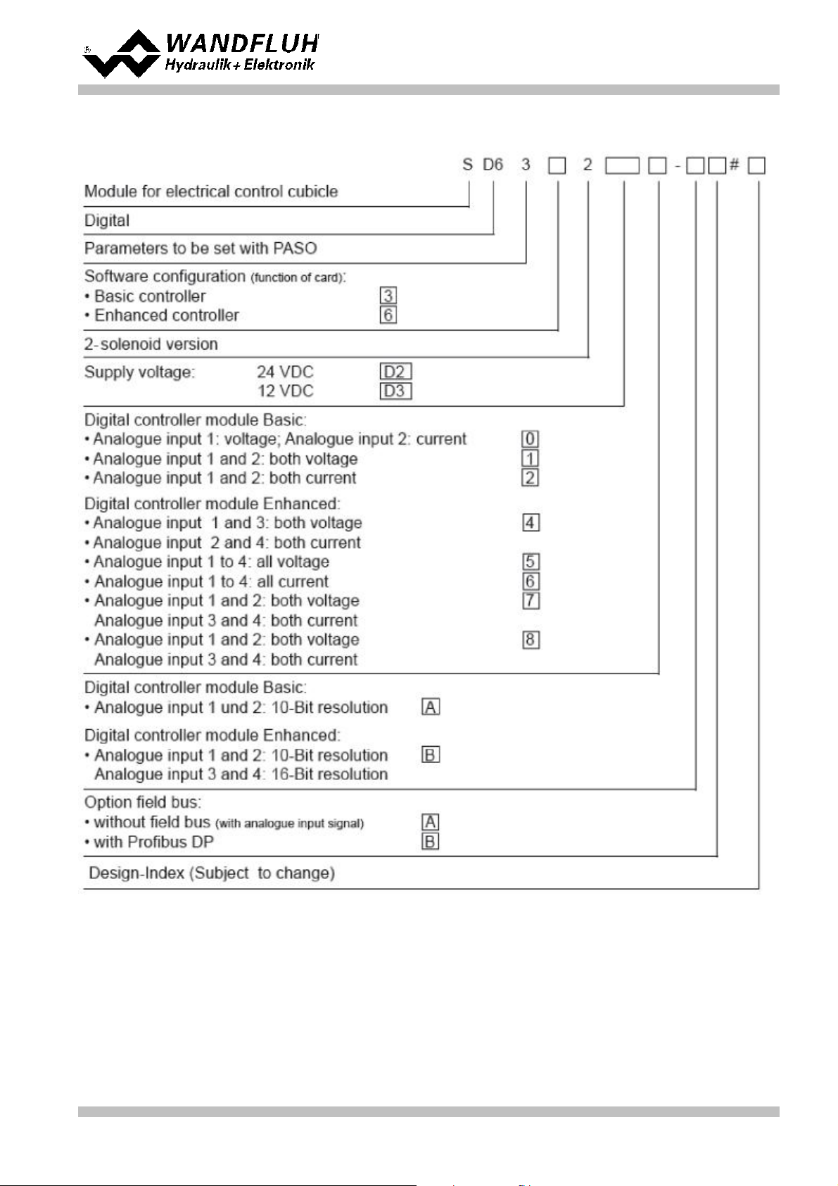
2.5 Type code
Operating instructions to Enhanced Controller module SD6
Wandfluh AG
Postfach
CH-3714 Frutigen
Tel: +41 33 672 72 72
Fax: +41 33 672 72 12
Email: sales@wandfluh.com
Internet: www.wandfluh.com
Page 4
Edition 12 14
SD636bae.pdf
Page 5
2.6 Technical Data
Design
Integrated in electronic case for top-hat rail clamping
Dimension
Amplifier and Basic Controller: 105 x 114 x 22.5mm
Enhanced Controller: 105 x 114 x 45mm
Amplifier and Controller with Profibus: 105 x 114 x 45mm
Mounting
For top-hat rail clamping
Weight
Amplifier and Basic Controller: 130g
Enhanced Controller: 220g
Amplifier and Controller with Profibus: 240g
Connection
Terminal screw blocks, max dimension 2.5mm
2
1 USB interface (connector type B)
Protection class
IP30 acc. to EN 60 529
Supply voltage
(depending on the type)
24 VDC
or 12 VDC
Voltage range
Supply voltage 24 VDC: 21 ... 30 VDC
Supply voltage 12 VDC: 10.5 ... 15 VDC
Ripple on supply voltage
< ±5 %
Fuse
Customer must integrate a slow fuse into his electrical system
Temperature drift
< 1% with DT = 40°C
No load current
40 ... 50 mA
Max. solenoid current
24VDC version 1.8 A
12VDC version 2.3 A
Analogue inputs
2 differential inputs 10-Bit (analogue input 1 + 2)
2 differential inputs 16-Bit (analogue input 3 + 4)
All inputs are not galvanically separated
SD6362DX4-BX
Analogue input 1:
Analogue input 2:
Analogue input 3:
Analogue input 4:
0...±10VDC
0...20mA, 4...20mA
0...±10VDC
0...20mA, 4...20mA
SD6362DX5-BX
Analogue input 1:
Analogue input 2:
Analogue input 3:
Analogue input 4:
0...±10VDC
0...±10VDC **
0...±10VDC
0...±10VDC
SD6362DX6-BX
Analogue input 1:
Analogue input 2:
Analogue input 3:
Analogue input 4:
0...20mA, 4...20mA
0...20mA, 4...20mA
0...20mA, 4...20mA
0...20mA, 4...20mA
SD6362DX8-BX
Analogue input 1:
Analogue input 2:
Analogue input 3:
Analogue input 4:
0...±10VDC
0...±10VDC
0...20mA, 4...20mA
0...20mA, 4...20mA
SD6362DX8-BX
Analogue input 1:
Analogue input 2:
Analogue input 3:
Analogue input 4:
0...20mA, 4...20mA
0...20mA, 4...20mA
0...±10VDC
0...±10VDC
**) 0...10VDC on SD6 with Profibus
2.6.1 General specifications
2.6.2 Electrical specifications
Operating instructions to Enhanced Controller module SD6
Wandfluh AG
Postfach
CH-3714 Frutigen
Tel: +41 33 672 72 72
Fax: +41 33 672 72 12
Email: sales@wandfluh.com
Internet: www.wandfluh.com
Page 5
Edition 12 14
SD636bae.pdf
Page 6
Operating instructions to Enhanced Controller module SD6
Input resistance
Voltage input against ground > 18 kOhm
Burden for current input = 250 Ohm
Input for digital sensors
9-pin D-SUB connector with RS-422 interface for SSI and
Start/Stop sensors
Digital inputs
8 inputs active-high
Switching threshold high 6 - 30VDC
Switching threshold low 0 - 1VDC
Serial interface
1 USB interface (Connector Type B)
Stabilised output voltage
Supply voltage 24 VDC: + 10 VDC
Supply voltage 12 VDC: + 8 VDC
max. load 30 mA
Solenoid current
Minimum current Imin adjustable 0 ... 950 mA
Maximum current Imax adjustable
- Supply voltage 24 VDC: Imin ... max. 1.8 A
- Supply voltage 12 VDC: Imin ... max. 2.3 A
Dither
Frequency adjustable 20 ... 250 Hz
Level adjustable 0 ... 200 mA
Analogue output
Output voltage range
max. load
+/– 10 VDC
+/– 3 mA
Digital outputs
4 outputs Lowside Switch.
Umax 40 VDC
Imax -0.7 A
EMC
Immunity
Emission
EN 61000-6-2
EN 61000-6-4
Storage
packing:
The module must be stored in the original packing
Temperature range:
-25 ... +85° C
Resistance to alkali and acid:
The module must be protected against alkalis and
acids
In operation
Temperature range
-20 ... +70° C
The total solenoid current of simultaneously
powered solenoids depends on the ambient
temperature.
Further information can be found in chapter
Solenoid outputs and ambient temperature .
Resistance to alkali and acid:
The module must be protected against alkalis and
acids
2.6.3 Environment
7
Wandfluh AG
Postfach
CH-3714 Frutigen
Tel: +41 33 672 72 72
Fax: +41 33 672 72 12
Email: sales@wandfluh.com
Internet: www.wandfluh.com
Page 6
Edition 12 14
SD636bae.pdf
Page 7
Operating instructions to Enhanced Controller module SD6
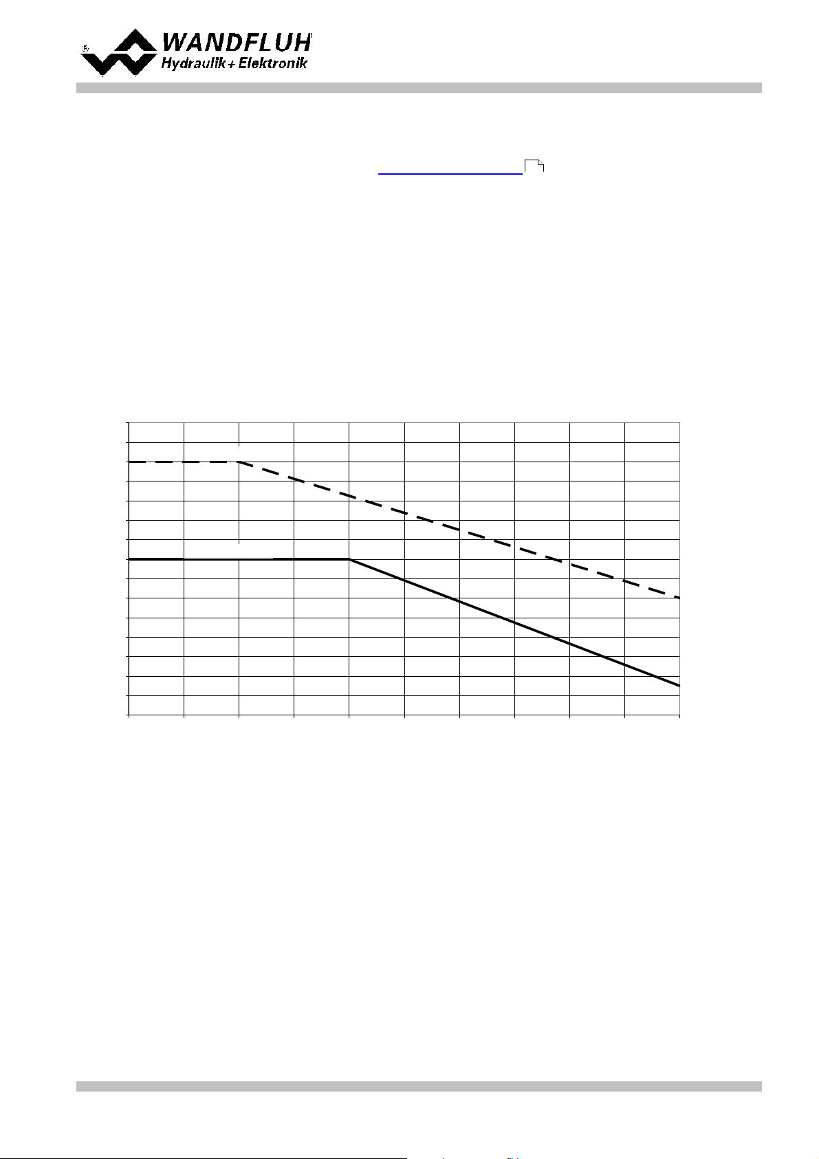
SD6: Derating of Total Solenoid Current when both Solenoid Outputs activated simultaneously
2000
2200
2400
2600
2800
3000
3200
3400
3600
3800
4000
4200
4400
4600
4800
5000
20 25 30 35 40 45 50 55 60 65 70
Ambient Temperature [°C]
Total Solenoid Current [mA]
Derating for 12V SD6
Derating for 24V SD6
2.6.4 Solenoid Outputs and Ambient Temperature
If only one solenoid output is powered at a time, then there are no restrictions and the single solenoid current
may reach the maximum current according to the Electrical Specifications over the whole temperature range.
5
But the total solenoid current of simultaneously powered solenoids depends on the ambient temperature.
Exceeding this current limit will trip the overcurrent protection circuit, the SD6 falls into the failure state and
blocks all function.
Solenoids can be powered simultaneously, i.e.on the amplifier in operating mode 4, or with inverted solenoid
outputs.
If solenoids are powered with more voltage than their nominal voltage and are so over-energized, then at fast
switching-on, the overcurrent protection may trip and the SD6 may fall into failure state and block all function.
The following graphics shows the maximum allowed total solenoid current over ambient temperature when both
solenoids are powered at the same time.
Wandfluh AG
Postfach
CH-3714 Frutigen
Tel: +41 33 672 72 72
Fax: +41 33 672 72 12
Email: sales@wandfluh.com
Internet: www.wandfluh.com
Page 7
Edition 12 14
SD636bae.pdf
Page 8
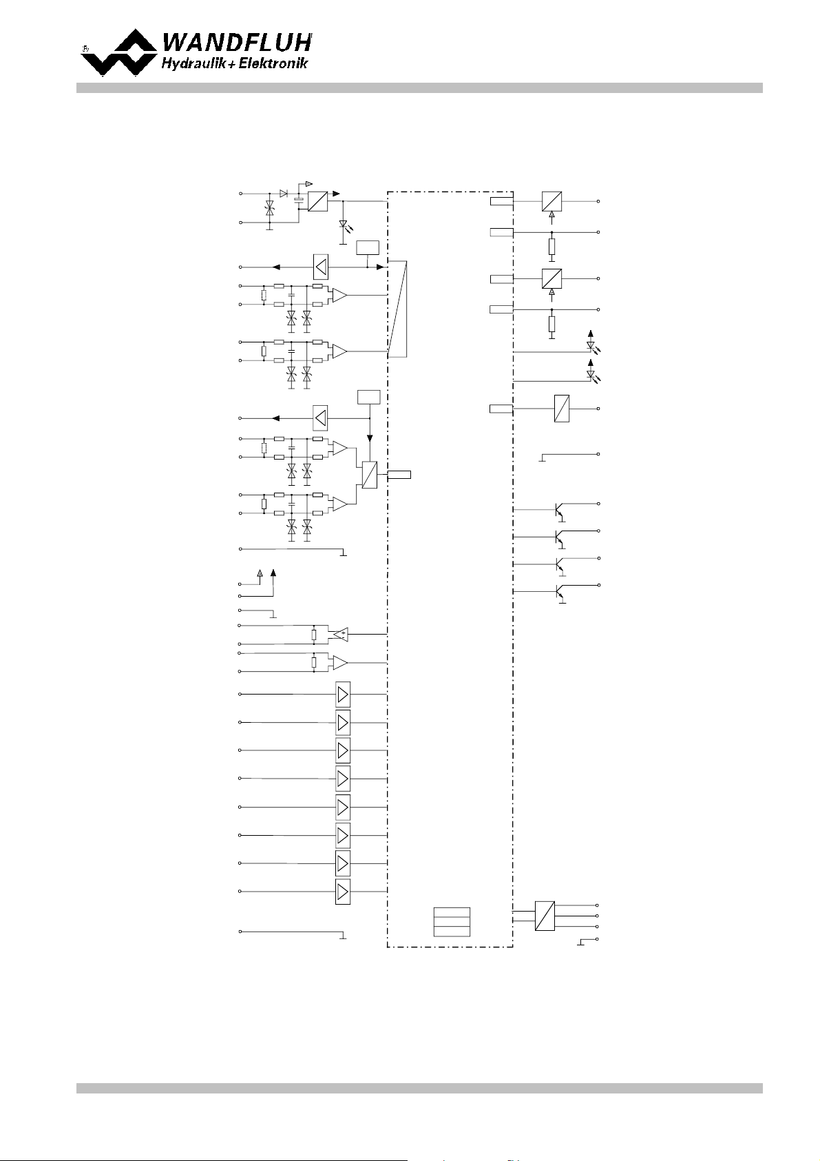
LED red
LED yellow
DC
DC
X1-5
X1-6
X1-7
Supply voltage
Stailized
output voltage
+
0 VDC
LED
green
X1-9
X1-10
-
+
Analogue input 1
X1-11
X1-12
-
+
Analogue input 2
X1-1
Digital input 1
X1-2
Digital input 2
Digital ground
Solenoid A
U
I
X1-15
X1-16
Solenoid B
U
I
X1-13
X1-14
Digital output 1
X1-3
Digital output 2
X1-4
Microcontroller
FEPROM
RAM
EEPROM
PWM
A/D
PWM
A/D
+
-
+
-
A
D
Digital output 3
Digital output 4
-
Analogue input 3
-
+
Analogue input 4
+
-
+
-
A
D
10-Bit
16-Bit
Stailized
output voltage
Ref
SPI
Digital input 3
Digital input 4
Digital input 5
Digital input 6
Digital input 7
Digital input 8
SPI
D
A
12-Bit
Analogue output
X2-1
X2-2
X2-4
USBX2-3
+
-
Ref
Output +24VDC
Output +5VDC
Clock output +
Clock output Data input +
Data input -
Sensor-ground
Analogue ground
X1-8
Analog ground
X1-17
X1-18
X1-19
X1-20
X1-21
X1-22
X1-29
X1-31
X1-25
X1-26
X1-27
X1-28
+
X1-32
X1-30
X1-23
X1-24
X3-2
X3-1
X3-6
X3-5
X3-8
X3-9
X3-7
2.7 Block diagram
Driving through the analogue interface
Operating instructions to Enhanced Controller module SD6
Wandfluh AG
Postfach
CH-3714 Frutigen
Tel: +41 33 672 72 72
Fax: +41 33 672 72 12
Email: sales@wandfluh.com
Internet: www.wandfluh.com
Page 8
Edition 12 14
SD636bae.pdf
Page 9
Operating instructions to Enhanced Controller module SD6
3 Safety rules
3.1 Installation / Commissioning / Parameterisation
· These operating instructions have to be carefully studied beforehand and the instructions are to be complied
with.
· Prior to the installation, all power supply voltages and any other energy sources have to be disconnected.
· The installation/assembly must only be carried out by specialist personnel with electrical knowledge.
· Take into account precautionary measures concerning components on the module, which are subject to
damage as a result of electrostatic discharge.
· Wrong manipulations by the personnel cannot be prevented by the SD6-Electronics.
· Before the switching on of the supply voltage, the fuse protection, the correct wiring and the conformity of the
power supply voltage with the permissible supply voltage range have to be verified.
· The SD6-Electronics monitors the working conditions within the electronics and
within the installation. Uncontrolled movements or force changes caused by
unforeseen errors of the SD6-Electronics cannot be prevented in any case.
· Danger for persons has to be avoided by installing an emergency stop device which
cuts off the power to the system.
Wandfluh AG
Postfach
CH-3714 Frutigen
Tel: +41 33 672 72 72
Fax: +41 33 672 72 12
Email: sales@wandfluh.com
Internet: www.wandfluh.com
Page 9
Edition 12 14
SD636bae.pdf
Page 10

4 Construction and Function
Operating instructions to Enhanced Controller module SD6
Refer to section "Block diagram" .
8
4.1 Introduction
· All inputs and outputs have to be contacted through the terminal screw block
· At the device front panel, there is a USB interface, through which the parameterisation and the diagnostics
can be made by using the PC-Parameterisation software PASO DSV/SD6
· In the factory, the SD6-Electronics are adjusted with the default values. The adjustment to the valves being
used, has to performed by the user.
4.2 Description of the Function
With the SD6-Electronics, it is possible to build different closed circuit controls. Apart from controls for pressure,
volume flow or position, also pQ- and alternating controls can be implemented. They can optionally be adjusted
in the form of a controller mode. In addition, an amplifier part is integrated, with which the connected valve resp.
its solenoid is directly driven.
The command value is conducted to the controller as an electric signal, a sensor records the feedback value,
this signal is also conducted to the controller. In correspondence with the control difference (command value feedback value), a control signal (solenoid current) is output to the valve.
By means of the scaling of the command value and feedback value, all further inputs can be made in the
required, resp., selectable physical unit (e.g., bar or mm, etc.). When the command value has been reached,
then the SD6 is capable of outputting a digital signal (optionally an „Error“- or „Target window reached “ - signal).
The SD6 - controller has a command value generator, with which the up - and down ramp of the internal
command value can be predefined. The controller is designed as a PID - controller. The control characteristics
as a result of this can be equalised and adapted to the control circuit. Furthermore, it is also possible to
switch-off the control system completely for testing - and adjusting purposes. The SD6 in this case operates in
correspondence with normal amplifier electronics.
Furthermore the controller module “SD6” comprises digital inputs for the enabling, for controlling the manual
operation and for the profile generator as well as digital outputs, which output the conditions „Error“ or „Target
window reached “.
Changed parameters can be saved in a non-volatile memory, so that following a renewed switching-on of the
control system they are still available once again.
The SD6 - electronics in addition have a signal recording function. By means of PASO, this makes possible a
recording of different system signals, such as, e.g., command value / feedback value, control difference,
solenoid currents, etc., which are able to be graphically displayed on a common time axis.
The manual operating mode makes available commands such as Forwards, Backwards, Rapid Speed and
Creep Speed. With this it is possible to put the connected hydraulics into operation without a super-ordinate
control system.
4.3 Characteristic optimisation
The SD6 electronics are provided with a possibility to optimise the characteristic “Preset value input – solenoid
current output”. The user is able to create a characteristic (e.g. a linearised characteristic) which matches his
own application. The characteristic optimisation can be turned on or off (refer to “Parameters_Valves” on page
21). This setting is available only with a SD6-electronics with software version higher than 1.1.1.6 and PASO with
software version higher than 1.5.0.9!
Wandfluh AG
Postfach
CH-3714 Frutigen
Tel: +41 33 672 72 72
Fax: +41 33 672 72 12
Email: sales@wandfluh.com
Internet: www.wandfluh.com
Page 10
Edition 12 14
SD636bae.pdf
Page 11
Operating instructions to Enhanced Controller module SD6
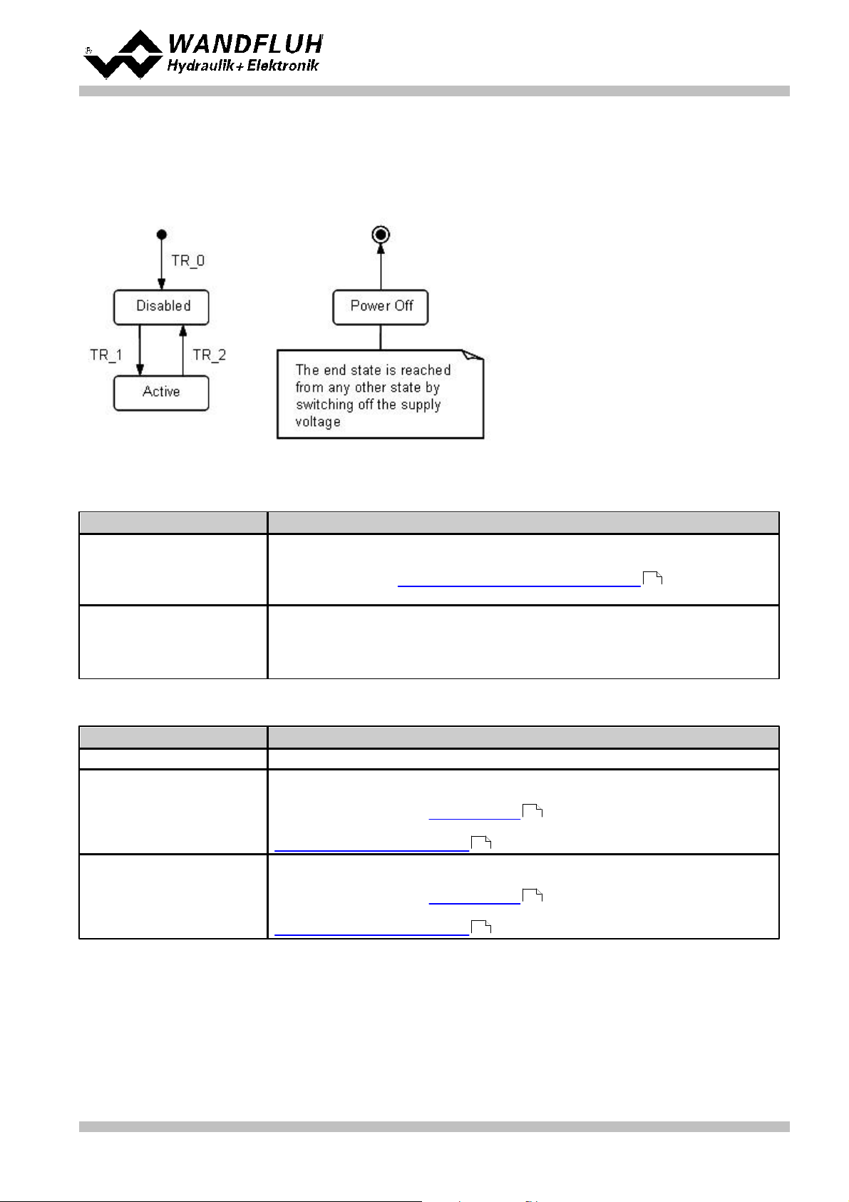
Status
Description
Disabled
· The SD6-Electronics are disabled, no solenoid current will be active
· In this state, with the command "Local operation" resp. "PASO operation"
(refer to section "Commands_Local Operating / PASO" ) the operating
mode can be set.
Active
· The SD6-Electronics are enabled
· The SD6-Electronics can be operated according to the selected operating
mode
· Changing the operating mode is not possible
Transition
Description
TR_0
Switching-on the supply voltage
TR_1
Enable
This is made in the operating mode "Local" through the digital input "Enable
control" (refer to section "Digital inputs" ) and in the operating mode
"Remote PASO" through the command "Enable" (refer to section
"Commands_Disable / Enable" ).
TR_2
Disable
This is made in the operating mode "Local" through the digital input "Enable
control" (refer to section "Digital inputs" ) and in the operating mode
"Remote PASO" through the command "Enable" (refer to section
"Commands_Disable / Enable" ).
4.4 SD6 State machine
In the following, with the help of a status diagram it is described, how the start-up of the SD6-Electronics takes
place and which statuses are reached when and how.
The following table describes the possible statuses and what is done in these statuses:
The following table describes the transitions from one status to the next one:
13
72
13
72
Wandfluh AG
Postfach
CH-3714 Frutigen
Tel: +41 33 672 72 72
Fax: +41 33 672 72 12
Email: sales@wandfluh.com
Internet: www.wandfluh.com
72
Page 11
Edition 12 14
SD636bae.pdf
Page 12
Operating instructions to Enhanced Controller module SD6
Operating mode
Activating with
Description
Local
Menu point "Commands_Local Operating"
Operating via analogue and digital inputs
on the SD6-Electronics
Remote PASO
Menu point "Commands_PASO Operating
Operating direct with the PASO
SD6-Type
Analogue input 1
(10-bit resolution)
Analogue input 2
(10-bit resolution)
Analogue input 3
(16-bit resolution)
Analogue input 4
(16-bit resolution)
SD6362DX4-BX
0...10VDC
0...±10VDC
(only with 2-sol
control modes)
0...20mA, 4...20mA
0...10VDC
0...±10VDC
(only with 2-sol
control modes)
0...20mA, 4...20mA
SD6362DX5-BX
0...10VDC
0...±10VDC
(only with 2-sol
control modes)
0...10VDC
0...±10VDC **
(only with 2-sol
control modes)
0...10VDC
0...±10VDC
(only with 2-sol
control modes)
0...10VDC
0...±10VDC
(only with 2-sol
control modes)
SD6362DX6-BX
0...20mA, 4...20mA
0...20mA, 4...20mA
0...20mA, 4...20mA
0...20mA, 4...20mA
SD6362DX7-BX
0...10VDC
0...±10VDC
(only with 2-sol
control modes)
0...10VDC
0...±10VDC **
(only with 2-sol
control modes)
0...20mA, 4...20mA
0...20mA, 4...20mA
SD6362DX8-BX
0...20mA, 4...20mA
0...20mA, 4...20mA
0...10VDC
0...±10VDC
(only with 2-sol
control modes)
0...10VDC
0...±10VDC
(only with 2-sol
control modes)
4.5 Operating mode
The SD6-Electronics have 2 operating modes. The following table describes, what can be done in the different
operating modes and how they can be activated:
The current operating mode is displayed in the status line (refer to section "Starting of PASO DSV/SD6" ).
86
For more information about the operating mode "Local" and "Remote", please refer to section
"Commands_Local Operating / PASO" .
72
4.6 Analogue inputs
· The applied analogue signal is digitised in the 10Bit A/D converter at analogue inputs 1 and 2 resp. in the 16Bit
A/D converter at analogue inputs 3 or 4.
Attention: By the input range 4 ... 20mA, the resolution is < 10Bit resp. < 16Bit!
· Differential inputs
All analogue inputs are differential inputs. Differential inputs are used if the ground potential of the external
command value generator does not agree with the ground on the SD6-Electronics.
If the differential input is intended to use like an analogue input against ground, the - (minus) connection of the
differential input must be connected to the ground of the SD6-Electronics. In this case please attend that the
solenoid current can cause a voltage drop between the SD6-Electronics and the power supply. It is
recommended to connect the - (minus) connection as near as possible to the power supply.
**) 0...+10VDC on SD6 with Profibus
Wandfluh AG
Postfach
CH-3714 Frutigen
Tel: +41 33 672 72 72
Fax: +41 33 672 72 12
Email: sales@wandfluh.com
Internet: www.wandfluh.com
Page 12
Edition 12 14
SD636bae.pdf
Page 13
Operating instructions to Enhanced Controller module SD6
4.7 Cablebreak detection
The analogue inputs with input signal range of 4...20mA can be detected for a cablebreak. If a cablebreak is
present (input signal less than 3mA), the corresponding solenoid outputs will be blocked and the output "Error"
will be active. The following conditions had to be performed:
· The input signal must be a current value 4 ... 20mA
· The parameter "Cablebreak" must be on "On"
Attention: Until a cablebreak will be detected, a time delay of about 100ms will pass. During this time, the
cylinder can make unintentional movements or unintentional force changes.
4.8 Digital inputs
· Digital input 1 " Enable control"
The digital input is active-high (refer to section "Electrical specifications" ).
If this input is set, the SD6-Electronics are enabled. Without this enable, no solenoid current will be output.
This digital input can be set also through the parameterisation software PASO DSV/SD6 (refer to section
"Configuration_Digital I/O" ).
65
· Digital input 2 "Automatic / Manual operation"
At manual operation (digital input low) the command value is being generated by digital inputs 3...5. For this
two velocities are available in both directions.
At automatic operation (digital input high) the command value is being generated by the profile generator or
read from an analog input, depending on the state of the digital inputs 3...8.
To switch between manual and automatic operation, the SD6 has to be disabled by deactivating digital input
1.
· Digital input 3 "Manual forward" or "Profile / Sequence"
Manual operation: When the digital input is activated the command value will be incremented. The velocity
depends on digital input 5 "Rapid speed / Creep speed".
Automatic operation: Choice between running through a complete profile (digital input high) or an individual
sequence (digital input low).
· Digital input 4 "Manual reverse" or "Start"
Manual operation: When the digital input is activated the command value will be decremented. The velocity
depends on digital input 5 "Rapid speed / Creep speed".
Automatic operation: Depending on digital input 3 "Profile / Sequence" the running through of the complete
profile or of the next sequence only is started.
· Digital input 5 "Rapid speed / Creep speed" or "Stop"
Manual operation: Changeover between rapid speed (digital input high) and creep speed (digital input low).
Automatic operation: As long as the digital input is high the axis can move. As soon as the digital input
becomes low the movement is stopped (set-point value = feedback value).
· Digital input 6...8 "Profile selection"
These digital inputs only take effect in automatic operation. Profiles can only be used in closed loop control
modes (an exception is the pQ-control mode, where no profiles can be used). How to select the profiles is
shown in the table below. If profile 0 is selected the command value will be read from one of the analogue
input. A detailed description of the profiles is located in the section "Profile-Menu"
5
37
Wandfluh AG
Postfach
CH-3714 Frutigen
Tel: +41 33 672 72 72
Fax: +41 33 672 72 12
Email: sales@wandfluh.com
Internet: www.wandfluh.com
Page 13
Edition 12 14
SD636bae.pdf
Page 14
Operating instructions to Enhanced Controller module SD6
Digital input 6
Digital input 7
Digital input 8
Profile
000
* 0 (analogue command value)
100101021103001410150116111
7
* with control mode "Alternating control (2-sol)" the analogue command value will not read if profile selection
is 0. In this case, the command value will be set to the actual value (= axis remains controlled at the actual
position). Should be used an analogue command value, the corresponding signal type must be selected
(refer to section "Configuration_Signal Scaling ").
53
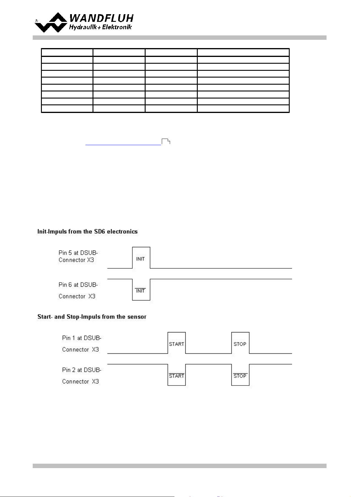
4.9 Input for digital sensor
This input makes it possible to connect digital sensors with SSI- or Start/Stop-Interface.
SSI-Interface
SSI-Interface according RS-422 standard with a baudrate of 300kHz.
Start/Stop-Interface
This Interface supports sensors with a Start/Stop-Interface as they are available e.g. from Balluff or MTS.
Wandfluh AG
Postfach
CH-3714 Frutigen
Tel: +41 33 672 72 72
Fax: +41 33 672 72 12
Email: sales@wandfluh.com
Internet: www.wandfluh.com
Page 14
Edition 12 14
SD636bae.pdf
Page 15

4.10 Outputs
· Proportional solenoid outputs A and B
The max. 2 solenoid outputs have a current output with 1000 Hz Pulse-Width-Modulation with superimposed
dither.
· Analog output
The analog output can be assigned to the following signals via the PASO DSV/SD6 (depending on the control
mode, different signals are available):
- command value for the solenoid driver
- scaled command value
- scaled feedback value (only with closed loop control modes)
- scaled control deviation (only with closed loop control modes)
The signal at the analog output can be used for driving a valve with integrated electronics which has a voltage
interface. The output level can be adjusted (refer to section "Configuration_Analog output" ).
· Digital outputs
The following digital outputs are available:
- Digital outut 1 "Error"
- Digital outut 2 "Solenoid B active", "Inside target window / End of Seq"
- Digital outut 3 "Trailing error"
- Digital outut 4 "Profile End reached"
The digital output can be configured by the PASO DSV/SD6 Software (refer to section "Configuration_Digital
I/O" ).
Operating instructions to Enhanced Controller module SD6
65
65
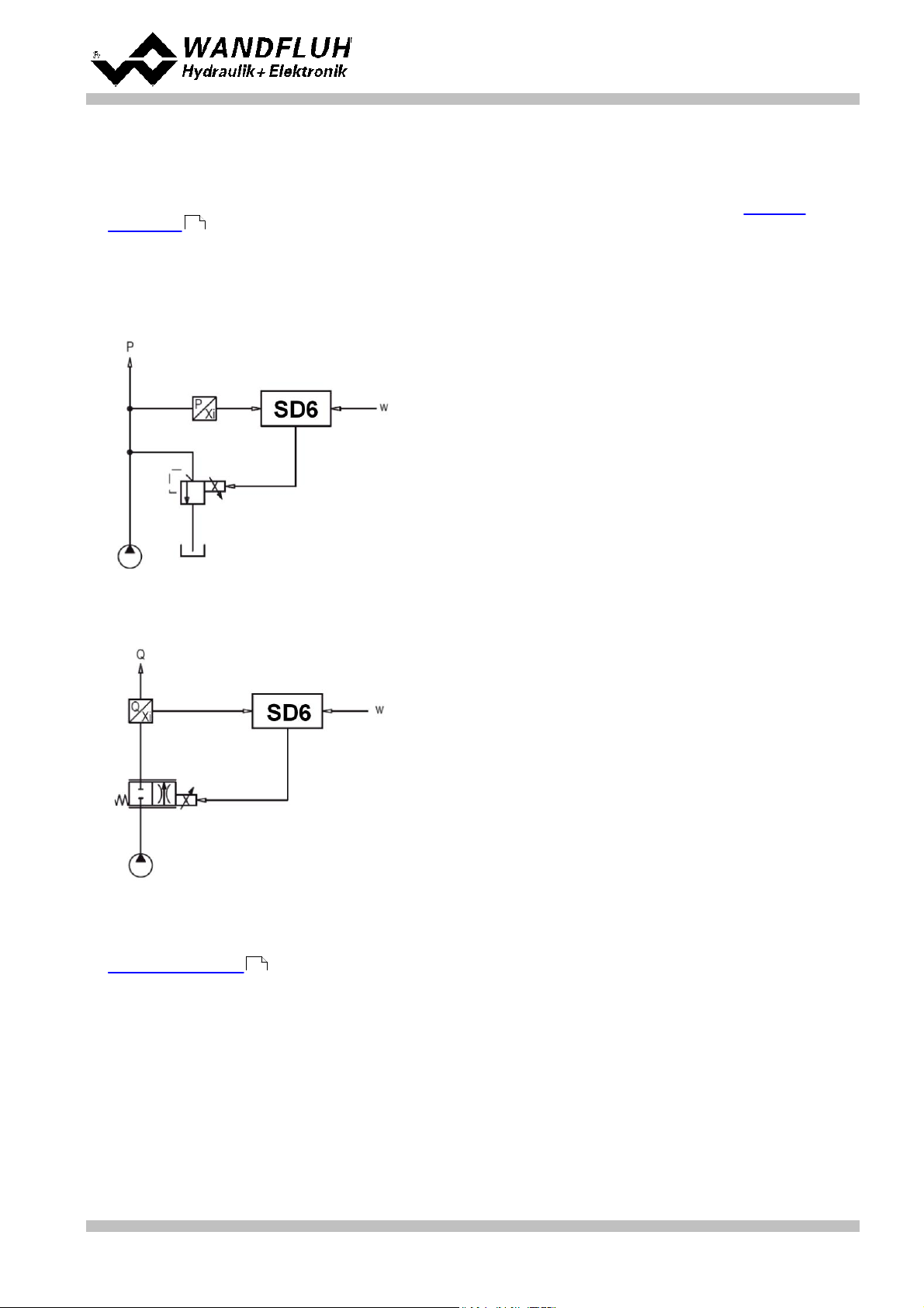
4.11 Controller Modes
The SD6-Electronics provide the following controller modes:
· Controller mode 3 "Pressure/flow valve open loop"
Control of a pressure relief-, pressure reducing- or flow control valve in open loop (without feedback signal).
The number of solenoids, which are activated, depends on the selected mode of operation (refer to section
"Mode of operation" ).
This mode of operation corresponds to the "Device Control Mode = 3" of the fieldbus device profile Fluid
Power Technology.
52
Wandfluh AG
Postfach
CH-3714 Frutigen
Tel: +41 33 672 72 72
Fax: +41 33 672 72 12
Email: sales@wandfluh.com
Internet: www.wandfluh.com
Page 15
Edition 12 14
SD636bae.pdf
Page 16
Operating instructions to Enhanced Controller module SD6
· Controller mode 4 "Pressure/flow valve closed loop (1-sol)"
Control of a 1-solenoid pressure relief-, pressure reducing- or flow control valve in closed loop (with feedback
signal). It can only be activated one solenoid (correspond to solenoid driver 1).
In this controller mode, the parameter "Mode of operation" has no meaning (refer to section "Mode of
Operation" ).
52
This mode of operation corresponds to the "Device Control Mode = 4" of the fieldbus device profile Fluid
Power Technology.
Example Application:
Pressure Control: with one proportional pressure relief valve, the pressure p is held constant to the command
pressure value w.
Example Application: Flow Control: with one proportional throttle valve, the flow Q is held constant to the flow
command value w.
· Controller mode 6 "Position open loop"
Control of a spool valve in open loop (without feedback signal).
The number of solenoids, which are activated, depends on the selected mode of operation (refer to section
"Mode of operation" ).
52
This mode of operation corresponds to the "Device Control Mode = 6" of the fieldbus device profile Fluid
Power Technology.
Wandfluh AG
Postfach
CH-3714 Frutigen
Tel: +41 33 672 72 72
Fax: +41 33 672 72 12
Email: sales@wandfluh.com
Internet: www.wandfluh.com
Page 16
Edition 12 14
SD636bae.pdf
Page 17
Operating instructions to Enhanced Controller module SD6
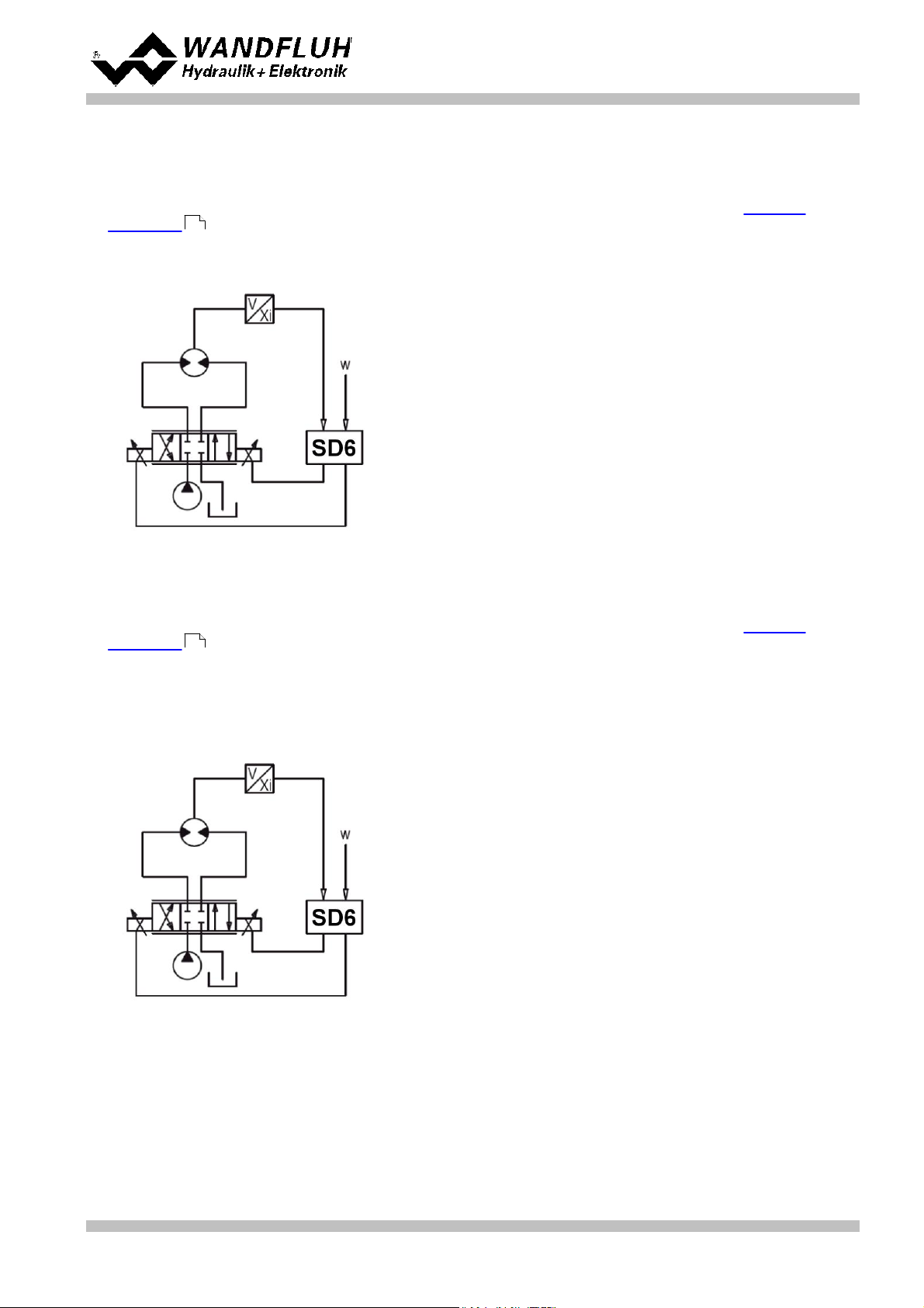
· Controller mode 7 "Speed control closed loop (2-sol)"
Control of a 2-solenoid pressure relief-, pressure reducing- or flow control valve in closed loop (with feedback
signal). It can be activated two solenoids.
In this controller mode, the parameter "Mode of operation" has no meaning (refer to section "Mode of
Operation" ).
52
This mode of operation corresponds to the "Device Control Mode = 7" of the fieldbus device profile Fluid
Power Technology.
· Controller mode 9 "Position closed loop"
Control of a 2-solenoid spool valve in closed loop (with feedback signal). It can be activated two solenoids.
In this controller mode, the parameter "Mode of operation" has no meaning (refer to section "Mode of
Operation" ).
52
This mode of operation corresponds to the "Device Control Mode = 9" of the fieldbus device profile Fluid
Power Technology.
Example application: with a 4/3-proportional-spool valve, the axis position is held constant to the command
position value w..
· Controller mode –5 "Pressure control closed loop (2-sol)"
Wandfluh AG
Postfach
CH-3714 Frutigen
Tel: +41 33 672 72 72
Fax: +41 33 672 72 12
Email: sales@wandfluh.com
Internet: www.wandfluh.com
Page 17
Edition 12 14
SD636bae.pdf
Page 18
Operating instructions to Enhanced Controller module SD6
Control of two 1-solenoid throttle valves in closed loop (with feedback signal) as a pressure reducing system.
One throttel valve is the loading valve, the other throttel valve is the unloading valve. The loading valve
corresponds to solenoid driver 1, the unloading valve to the solenoid driver 2.
In this controller mode, the parameter "Mode of operation" has no meaning (refer to section "Mode of
Operation" ).
52
This controller mode is a WANDFLUH specific controller mode and does not correspond to the fieldbus
device profile Fluid Power Technology.
This setting is available only with a SD6-electronics with software version > 1.1.1.6 and PASO with software
version > 1.5.0.9!
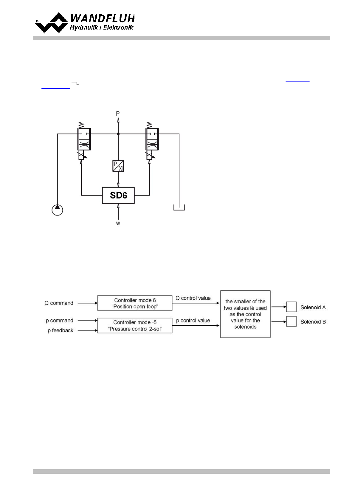
· Controller mode –9 "pQ control (2-sol)"
Driving of a direction control valve in open loop control circuit (without feedback signal) with monitoring of a
predefined pressure (with feedback signal).
There is a Q and a p command value. With the Q command value, the cylinder can move in open loop in both
directions. The p command value defines the maximum allowed pressure. If this pressure is exceeded, the
controller reduces the output signal to the valve. In this case the preset pressure is not exceeded. A rear
dodge (cylinder moves backward) is possible. The p feedback value can be either an absolute signal (V or
mA) from a pressure or force sensor or can be built as a differential signal from two pressure or force sensors
(V or mA).
With this controller mode, the choice of the proportional valve has a high influence on the system behavior.
More details about it are available from factory.
Example application: with a 4/3-proportional-spool valve, the axis will move in open loop (without feedback
signal). Simultaneously the pressure is monitored (measured with the pressure sensor).
Wandfluh AG
Postfach
CH-3714 Frutigen
Tel: +41 33 672 72 72
Fax: +41 33 672 72 12
Email: sales@wandfluh.com
Internet: www.wandfluh.com
Page 18
Edition 12 14
SD636bae.pdf
Page 19
Operating instructions to Enhanced Controller module SD6
This setting is available only with a SD6-electronics with software version higher than 1.1.3.0 and PASO with
software version higher than 1.5.1.2!
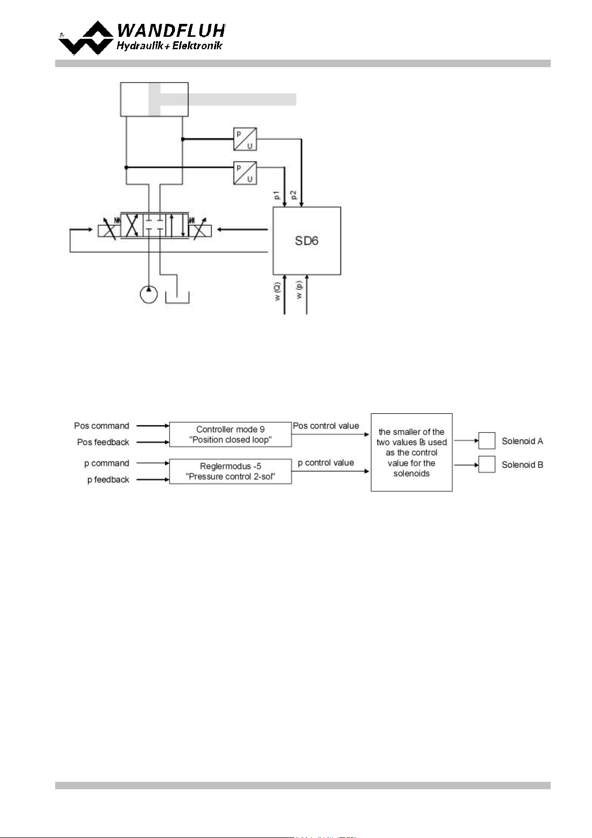
· Controller mode –10 "Alternating control (2-sol)"
Driving of a direction control valve in closed loop control circuit (with feedback value return) with monitoring of
a predefined pressure (with feedback value return).
There is a pos and a p command value. With the pos command value, the cylinder can move in closed loop
in both directions. The p command value defines the maximum allowed pressure. If this pressure is
exceeded, the position controller is swichted off and the controller reduces the output signal to the valve. In
this case the preset pressure is not exceeded. If the actual pressure is smaller than the p command value,
the position controller is switched on. A rear dodge (cylinder moves backward) is possible. The p feedback
value can be either an absolute signal (V or mA) from a pressure or force sensor or can be built as a
differential signal from two pressure or force sensors (V or mA).
With this controller mode, the choice of the proportional valve has a high influence on the system behavior.
More details about it are available from factory.
Example application: with a 4/3-proportional-spool valve, the axis position is held constant to the command
position value w. Simultaneously the pressure is monitored (measured with the pressure sensor).
Wandfluh AG
Postfach
CH-3714 Frutigen
Tel: +41 33 672 72 72
Fax: +41 33 672 72 12
Email: sales@wandfluh.com
Internet: www.wandfluh.com
Page 19
Edition 12 14
SD636bae.pdf
Page 20
Operating instructions to Enhanced Controller module SD6
This setting is available only with a SD6-electronics with software version higher than 1.1.3.0 and PASO with
software version higher than 1.5.1.2!
Wandfluh AG
Postfach
CH-3714 Frutigen
Tel: +41 33 672 72 72
Fax: +41 33 672 72 12
Email: sales@wandfluh.com
Internet: www.wandfluh.com
Page 20
Edition 12 14
SD636bae.pdf
Page 21
Operating instructions to Enhanced Controller module SD6
0%
...
100% command value
= Imin ... Imax solenoid A
0%
...
50% command value
= Imax ... Imin solenoid B
50%
...
100% command
value
= Imin ... Imax solenoid A
-100%
...
0% command value
= Imax ... Imin solenoid B
0%
...
100% command
value
= Imin ... Imax solenoid A
4.12 Mode of operation
The mode of operation is only of significance in controller mode "Pressure/flow valve open loop", "Position open
loop" and "pQ control (2-sol)". In all other controller modes the mode of operation is not taken into consideration.
The following 4 modes of operation are possible:
· Mode of operation 1 "Command value unipolar (1-solenoid)"
This mode of operation is only selectable with the 1-solenoid version.
With an analogue input (voltage or current) with a 1-solenoid valve the solenoid A is driven.
· Mode of operation 2 "Command value unipolar (2-solenoid)"
This mode of operation is only selectable with the 2-solenoid version.
With an analogue input (voltage or current) with a directional control valve, solenoid A and solenoid B are
driven.
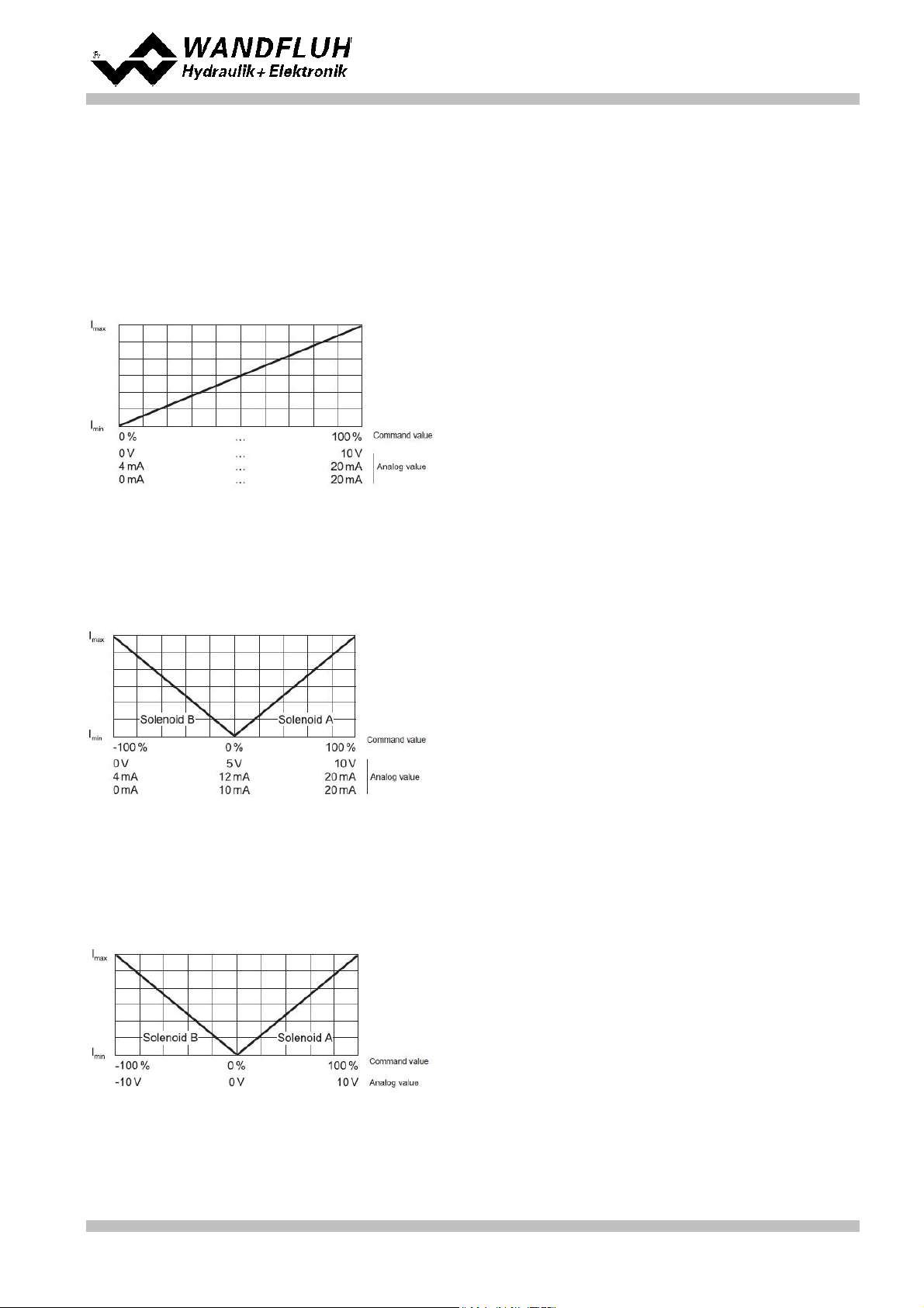
· Mode of operation 3 "Command value bipolar (2-solenoid)"
This mode of operation is only selectable with the 2-solenoid version.
With an analogue input (voltage) of 0 ... ±10V with a directional control valve, solenoid A (positive voltage)
and solenoid B (negative voltage) are driven.
Wandfluh AG
Postfach
CH-3714 Frutigen
Tel: +41 33 672 72 72
Fax: +41 33 672 72 12
Email: sales@wandfluh.com
Internet: www.wandfluh.com
Page 21
Edition 12 14
SD636bae.pdf
Page 22

Operating instructions to Enhanced Controller module SD6
0%
...
100% command
value,
= Imin ... Imax solenoid A
Digital input 2 "high":
0%
...
100% command
value,
= Imin ... Imax solenoid B
· Mode of operation 5 "Command value unipolar (2-solenoid)"
This mode of operation is only selectable with the 2-solenoid version.
With an analogue input (voltage or current) with a directional control valve, depending on the digital input 2,
solenoid A or solenoid B is driven.
Digital input 2 "low":
Wandfluh AG
Postfach
CH-3714 Frutigen
Tel: +41 33 672 72 72
Fax: +41 33 672 72 12
Email: sales@wandfluh.com
Internet: www.wandfluh.com
Page 22
Edition 12 14
SD636bae.pdf
Page 23
Operating instructions to Enhanced Controller module SD6
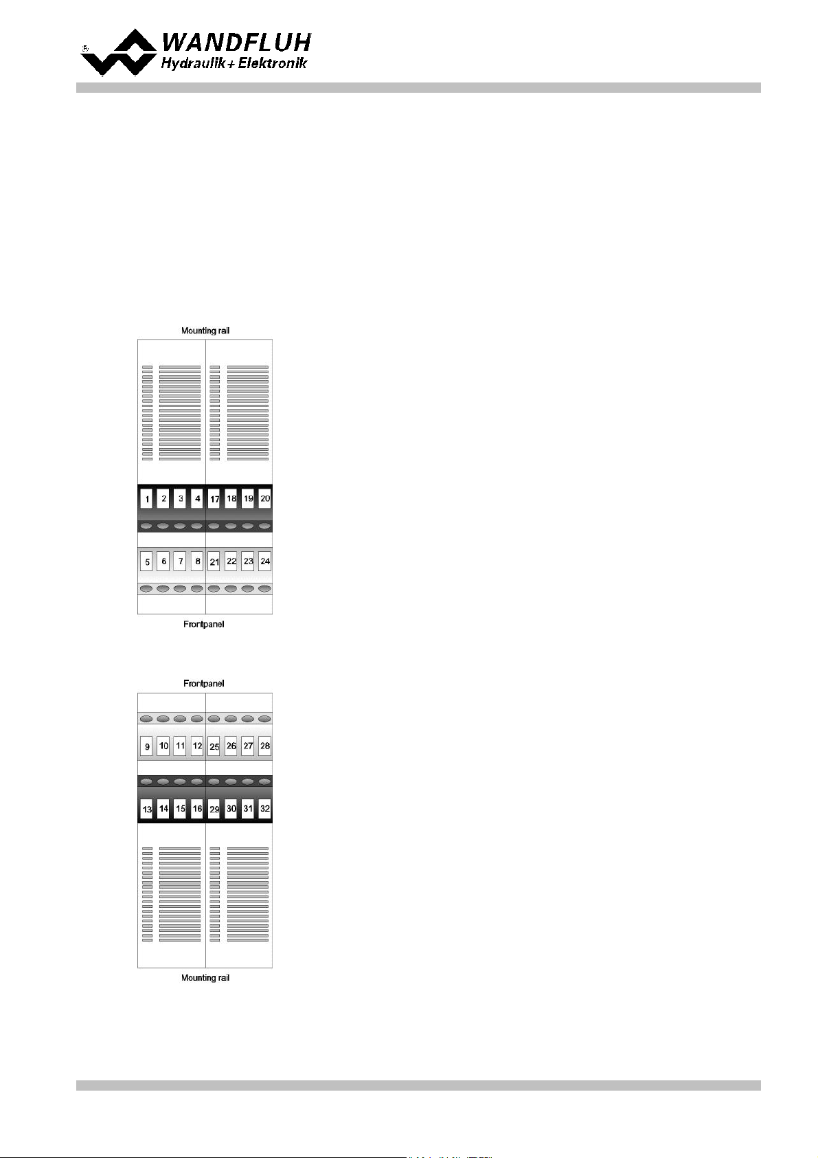
Top view of box
X1-1 = Digital input1
X1-2 = Digital input 2
X1-3 = Digital output 1
X1-4 = Digital output 2
X1-5 = Supply voltage +
X1-6 = Supply voltage 0 VDC
X1-7 = Stabilised output voltage
X1-8 = Analogue ground
X1-17 = Digital input 3
X1-18 = Digital input 4
X1-19 = Digital input 5
X1-20 = Digital input 6
X1-21 = Digital input 7
X1-22 = Digital input 8
X1-23 = Digital output 3
X1-24 = Digital output 4
Bottom view of box
X1-9 = Analogue input 1 +
X1-10 = Analogue input 1 X1-11 = Analogue input 2 +
X1-12 = Analogue input 2 X1-13 = Output Solenoid B +
X1-14 = Output Solenoid B X1-15 = Output Solenoid A +
X1-16 = Output Solenoid A X1-25 = Analogue input 3 +
X1-26 = Analogue input 3 X1-27 = Analogue input 4 +
X1-28 = Analogue input 4 X1-29 = Digital ground
X1-30 = Analogue ground
X1-31 = Stabilized output voltage
X1-32 = Analogue output
5 Operating and Indicating elements
5.1 General
All inputs and outputs have to be contacted through the terminal screw blocks. On the front panel of the
electronic housing, there is a USB interface, through which the parameterisation and the diagnostics can be
made by using the PC-Parameterisation software PASO DSV/SD6.
5.2 Screw terminator view
Wandfluh AG
Postfach
CH-3714 Frutigen
Tel: +41 33 672 72 72
Fax: +41 33 672 72 12
Email: sales@wandfluh.com
Internet: www.wandfluh.com
Page 23
Edition 12 14
SD636bae.pdf
Page 24

Operating instructions to Enhanced Controller module SD6
5.3 Control elements
5.3.1 General
The front panel of the SD6-Electronics contains the connector to the USB-Interface. Additionally the front panel
is provided with three LED's, which inform the user about the device functioning.
5.3.2 ERROR-LED (red)
The ERROR-LED displays, when an error is detected (refer to section "The system does not work" ).
80
5.3.3 FUNCTION-LED (yellow)
In the controller modes "Pressure/flow valve open loop" and "Position open loop" the FUNCTION-LED is lighting
as soon as a solenoid current is forced (solenoid A and/or solenoid B).
In the controller modes "Pressure/flow valve closed loop", "Speed control closed loop", "Position closed loop"
and "Pressure control closed loop" the FUNCTION-LED is lighting when the target window is reached.
In the controller modes "pQ-control" and "Alternating control" the FUNCTION-LED is lighting depending on the
state of the digital output 2 (refer to section "Configuration_Digital I/O" )
65
5.3.4 SUPPLY-LED (green)
The SUPPLY-LED is lighting, when the SD6-electronics are supplied.
Wandfluh AG
Postfach
CH-3714 Frutigen
Tel: +41 33 672 72 72
Fax: +41 33 672 72 12
Email: sales@wandfluh.com
Internet: www.wandfluh.com
Page 24
Edition 12 14
SD636bae.pdf
Page 25

Operating instructions to Enhanced Controller module SD6
View of the USB-interface:
1
2
3 4
X2-1 = VBUS
X2-2 = DX2-3 = D+
X2-4 = GND
5.3.5 USB-interface
The USB-interface allows the parameterisation and the analysis of the SD6-electronics by PASO software. The
connection to the PC is realised by standard USB-cables (USB Type A connector PC-side, USB Type B
connector SD6-side).
Connector USB Type B
Hint: The USB-cable is not included.
Wandfluh AG
Postfach
CH-3714 Frutigen
Tel: +41 33 672 72 72
Fax: +41 33 672 72 12
Email: sales@wandfluh.com
Internet: www.wandfluh.com
Page 25
Edition 12 14
SD636bae.pdf
Page 26
6 Commissioning
control extern control intern
6 ... 30V
control intern
max 40V / 0.7A
control extern
Operating instructions to Enhanced Controller module SD6
Please refer to section "Safety rules" .
9
6.1 Connection instructions
The contact assignment of the following description refers to section "Operating and Indicating elements" and
to section "Connection examples" .
28
For an installation / connection appropriate for EMC, the following points absolutely have to be observed:
· Cable length longer than 10m requires shielded cables. The shield of the cable must only be connected with
the earthing on the switchboard side using a large surface area and low Ohm connection.
· The top-hat rail has to be connected with the earthing with an as short as possible conductor with a strand
cross section >= 1.5 mm2.
· Solenoid- and signal cables must not be laid parallel to high voltage cables.
6.1.1 Supply voltage
· For the dimensioning of the power supply, the maximum current demand of the solenoids (in case of
directional control valves only the maximum current demand of 1 solenoid) has to be increased by the no load
current from the SD6-Electronics (refer to section "Electrical specifications" ).
5
· The limit values of the supply voltage and its residual ripple indispensably have to be complied with (refer to
section "Electrical specifications" ).
5
· The SD6-Electronics have to be protected with a slow acting fuse
23
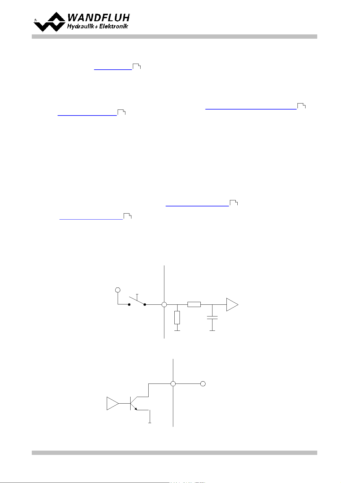
6.1.2 Digital inputs and outputs
· The digital inputs are active-high and not galvanically separated
· For activation, they have to be connected to a voltage between 6 ... 30VDC (e.g. power supply)
· The digital outputs are "Lowside Switch" outputs (open collector)
Wandfluh AG
Postfach
CH-3714 Frutigen
Tel: +41 33 672 72 72
Fax: +41 33 672 72 12
Email: sales@wandfluh.com
Internet: www.wandfluh.com
Page 26
Edition 12 14
SD636bae.pdf
Page 27
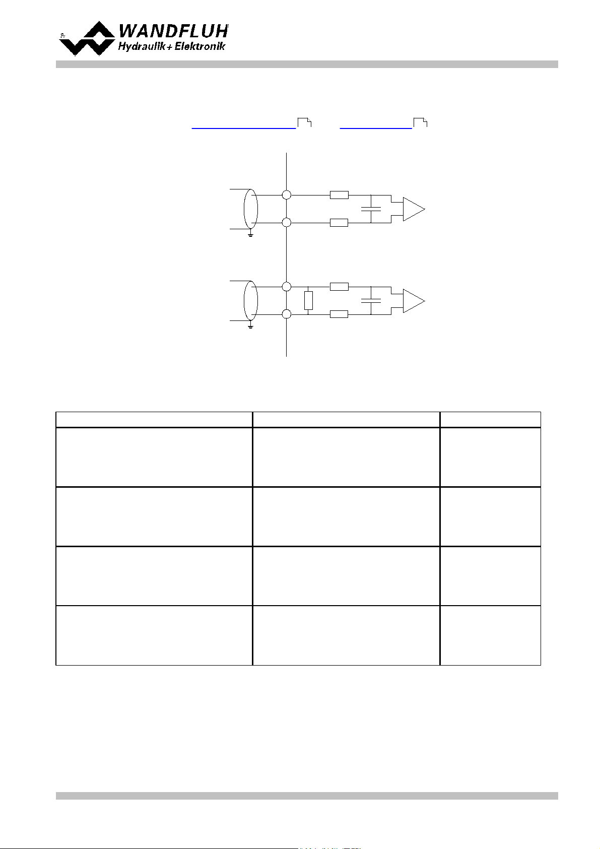
6.1.3 Analogue inputs 10-Bit and 16-Bit
· Depending on the card type current and / or voltage inputs with 10-bit ore possibly with 16-bit resolution are
available (rrefer to section "Electrical specifications " and "Analogue inputs ")
· All inputs are differential inputs.
control extern control intern
+
-
voltage
input
large surface
connection
+
-
current
input
large surface
connection
Input signal
Pin configuration screw terminators
Input range
Voltage against ground
10-Bit (example with AnaInp1):
+ at Pin X1-9 / Pin X1-10 at ground
16-Bit (example with AnaInp3):
+ at Pin X1-25 / Pin X1-26 at ground
0 ... +10V
0 ... ±10V
Differential voltage
10-Bit (example with AnaInp1):
+ at Pin X1-9 / - at Pin X1-10
16-Bit (example with AnaInp3):
+ at Pin X1-25 / - at Pin X1-26
0 ... +10V
0 ... ±10V
Current against ground
10-Bit (example with AnaInp2):
+ at Pin X1-11 / Pin X1-12 at ground
16-Bit (example with AnaInp4):
+ at Pin X1-27 / Pin X1-28 at ground
0 ... 20mA
4 ... 20mA
Differential current
10-Bit (example with AnaInp2):
+ at Pin X1-11 / - at Pin X1-12
16-Bit (example with AnaInp4):
+ at Pin X1-27 / - at Pin X1-28
0 ... 20mA
4 ... 20mA
Operating instructions to Enhanced Controller module SD6
5 12
6.1.4 Configuration of the analogue inputs 10-Bit and 16-Bit
The analogue inputs can be configured as follows:
Wandfluh AG
Postfach
CH-3714 Frutigen
Tel: +41 33 672 72 72
Fax: +41 33 672 72 12
Email: sales@wandfluh.com
Internet: www.wandfluh.com
Page 27
Edition 12 14
SD636bae.pdf
Page 28

6.1.5 Digital Sensor
X3-1 = Digital input + / Data +
X3-2 = Digital input – / Data X3-3 = Reserved
X3-4 = Reserved
X3-5 = Clock output + / Clock +
X3-6 = Clock output – / Clock X3-7 = Output +5VDC
X3-8 = Sensor-ground
X3-9 = Output +24VDC
Operating instructions to Enhanced Controller module SD6
This interface for digital sensors works as RS-422 standard (refer to section "Input for digital sensor" )
28
Pin assignment:
6.2 Connection examples
The contact assignment of the following description refers to section "Operating and Indicating elements" .
6.2.1 Position Control
23
Wandfluh AG
Postfach
CH-3714 Frutigen
Tel: +41 33 672 72 72
Fax: +41 33 672 72 12
Email: sales@wandfluh.com
Internet: www.wandfluh.com
Page 28
Edition 12 14
SD636bae.pdf
Page 29

7 Settings
Operating instructions to Enhanced Controller module SD6
Please refer to section "Safety Rules" .
9
7.1 Introduction
· The system- and parameter settings can be made via the RS232 interface with the PC-Parameterisation
software PASO DSV/SD6.
· For information about the operation via the PC-Parameterisation software PASO DSV/SD6 please refer to
section "PASO DSV/SD6 Installation and Operation".
· Depending on the connected SD6-Electronics, certain settings may be blocked.
7.2 Tips for the first commissioning
· Connect the power supply, leave the SD6-Electronics still switched-off.
· Switch-off the hydraulic drive (hydraulics switched-off).
· Carefully check the connections.
· Switch-on the power supply.
· Establish communication with PASO (connect PC and axis controller with a standard USB cable and start
PASO).
· Configure the SD6-Electronics specific to the installation. In doing so, the following sequence should be
observed:
1. Make the corresponding settings in the menu "Configuration_Controller mode "
2. Select the corresponding mode of operation In the menu "Configuration_Mode of operation " (only witht
open loop controller modes)
3. make the corresponding settings in the menu "Configuration_Signal scaling "
· Switch-on the hydraulics.
· For the card to be enabled, the digital input "Enable Control" has to be set (refer to section "Digital Input
").
· Corresponding to the set-point value command, the axis should now run up to the required position.
If the axis only runs up to the mechanical stop in one direction, then the system control sense is probably
wrong (change it in the menu point "Configuration_Controller mode ").
52
· The command value direction (e.g., potentiometer left/right) should correspond to the axis direction. If not,
either change the set-point value direction or the feedback value direction (change in the menu point "
Configuration_Signal scaling "). If the feedback value direction is reversed, then simultaneously the
53
connection of the solenoids 1 and 2 have to be switched.
· Set the drive currents of the valves in the menu "Parameter_Valves ".
· Set the control parameters in the menu "Parameter_Controller ".
· Make the settings in the menu "Parameter_Window ”.
50
43
48
52
52
53
65
Wandfluh AG
Postfach
CH-3714 Frutigen
Tel: +41 33 672 72 72
Fax: +41 33 672 72 12
Email: sales@wandfluh.com
Internet: www.wandfluh.com
Page 29
Edition 12 14
SD636bae.pdf
Page 30

Operating instructions to Enhanced Controller module SD6
· The parameter 'Imin A' resp. 'Imin B' should be set in the way that the axis just slightly move
· The parameter 'Imax A' resp. 'Imax B' should be set in the way that the max. desired speed is reached at the
axis
· Adjust the desired value for the target window (control deviation < target window threshold = target
window reached)
· Adjust the desired value for the trailing error window (control deviation > trailing error window threshold =
trailing error)
· Adjust the desired value for the solenoid-off window (control deviation < solenoid off window threshold =
solenoids are switched off)
Please note therfore the following:
· The solenoid off function is only active, if the parameter 'Solenoid In position' in the menu 'Configuration -
Control mode' is set to 'off'. If it sets to 'on', the solenoid are never switched off
· If the value for the parameter 'Solenoid off threshold' is higher than the value for the parameter 'Target
window threshold', then the target window will never be reached (the solenoids are switched off before the
target position is reached)
· Using the parameters of the PID controller , the control behavior can be adjusted
· Because a position control is a dynamic control system, it can be waived to the I-term in many cases
· First, the P-term should be set
· Therefore increase gradually the parameter 'P-Ampl' until the desired response time is reached, without the
system oscillates
· If necessary, the running in the final position can be changed with the I-term
· With the parameter 'Velocity feed forward', the riding of the cylinder can be accelerated. The change of the
command value (the increase speed of the command value) is multiplied with this factor and added to the
correcting variable of the controller. If this factor is 0, no command value addition is added to the correcting
variable
· The parameter 'Command feed forward' should be set to 0 in this control mode
· Set all controller parameters (P-Ampl, I-Window, I-Time, D-Ampl and D-Time, at a time positive and
negative) to 0
· Set parameter 'Command feed forward' to 1.0
· Change the preset value from min to max. The actual value should follow with a difference
· Change the value from the parameter 'Command feed forward' in the case that the difference between preset
and actual value is as small as possible. The difference is not the same over the whole range. Select the
smalles difference in the range, where the system will work mostly
· Increase the value from the parameter 'P-Ampl'. As long as the system does not start to swing, this
parameter can be increased
· Find out the highest control deviation (with the Menu 'Analysis - Signal recording' )
· The highest control deviation plus 10 bar will be the value for the parameter 'I-Window outside'
· Set parameter 'I-Window Inside' to 1 bar
· Set parameter 'I-Time' to 1 s. If the system is not fast enough, decrease the value from 'I-time'
7.3 Start up help
The following description is intended as a guide for the setting of a control system. It is important that the default
order is maintained. The value of each parameter is always system dependent. Larger deviations in the setting
can occur quiteof different systems.
Start up Position controller
50
50
50
52
Start up Pressure controller
48
48
76
Wandfluh AG
Postfach
CH-3714 Frutigen
Tel: +41 33 672 72 72
Fax: +41 33 672 72 12
Email: sales@wandfluh.com
Internet: www.wandfluh.com
Page 30
Edition 12 14
SD636bae.pdf
Page 31

Operating instructions to Enhanced Controller module SD6
· First, set the parameter for the position controller analog to the start up position controller (set Setup mode
to 'Position')
· Afterwards, set the parameter for the pressure controller analog to the start up pressure controller (set Setup
mode to 'Pressure')
· Please note therfore the following:
· The Dithersignal must be active resp. set high enough (lower frequency / higher level)
Therefore the adjusted values for Imin A resp. Imin B are also corrrect for the pressure controller
· The smaller of the two control values is active. A "stronger" controller loses out to a "weaker" controller.
With a corresponding adjustment it is possible to prioritized the position or pressure controller (e.g.
performs a fast integral to a higher control value and loses against the 'weak regulator')
· Set parameter "I-term, if control deviation > I-Window outside" to "leave value"
· Set parameter "I-term, if controller is not active" to "leave value"
· Set parameter 'Command feed forward' to 0
· The feedback pressure signal should be read as a differential pressure with two sensors (there can be a
problem with starting the movement with one sensor)
· With a double acting cylinder, the pressure feedback value should read in as a differential pressure with two
pressure sensor
· With a single acting cylinder, the pressure feedback value can read in also with only one pressure sensor.
This should be installed on the working side (active side).
· Instead of a pressure sensor also a force sensor can be used
· A 4/3-way spool valve with central position A-B-T connected (valve type ...-ADB-...) is not suitable
Start up pQ-controller and Alternating controller
73
73
43
48
48
48
Wandfluh AG
Postfach
CH-3714 Frutigen
Tel: +41 33 672 72 72
Fax: +41 33 672 72 12
Email: sales@wandfluh.com
Internet: www.wandfluh.com
Page 31
Edition 12 14
SD636bae.pdf
Page 32

Operating instructions to Enhanced Controller module SD6
Parameter
Werkseinstellung
Reglermodus
Achsposition gesteuert
Ausgang Magnet A
Strom nicht invertiert
Ausgang Magnet B
Strom nicht invertiert
Imin immer aktiv
nein
Systemregelsinn
nicht invertiert
Magnet 'In Position'
ein
Betriebsart
Sollwert unipolar (2-Mag)
Signaltyp Sollwert
0...10V
Benutzter Eingang Sollwert
Analogeingang 1
Invertierung Sollwert
nein
Kabelbruch-Überwachung Sollwert
nein
Skalierung Sollwert
20.000 %/V
Offset Sollwert
0.00 V
Min. Interface Sollwert
0.000 V
Max. Interface Sollwert
10.000 V
Min. Reference Sollwert
0.0 mm
Max. Reference Sollwert
100.0 mm
Signaltyp Istwert
0...10 V
Benutzter Eingang Istwert
Analogeingang 3
Kabelbruch-Überwachung Istwert
nein
Min. Interface Istwert
0.000 V
Max. Interface Istwert
10.000 V
Min. Reference Istwert
0.0 mm
Max. Reference Istwert
100.0 mm
Offset Istwert
0.00 mm
Auflösung Istwert
0.005 mm/Inc
Max. Reference digitales Messsystem
100.00 mm
Bit Anzahl SSI
24
v-Ausbreitung Istwert
2850880 mm/s
Anzeige Einheit
mm
Totband
0.0 %
IminA
150 mA
ImaxA
700 mA
IminB
150 mA
ImaxB
700 mA
Min. Interface Analogausgang
-10.00V
Max. Interface Analogausgang
10.00V
Rampe A auf
0.00 s
Rampe A ab
0.00 s
Rampe B auf
0.00 s
Rampe B ab
0.00 s
Geschwindigkeit +
1000 mm/s
7.4 Default settings
In the factory, the SD6-Electronics will be set to the following default values:
Wandfluh AG
Postfach
CH-3714 Frutigen
Tel: +41 33 672 72 72
Fax: +41 33 672 72 12
Email: sales@wandfluh.com
Internet: www.wandfluh.com
Page 32
Edition 12 14
SD636bae.pdf
Page 33

Operating instructions to Enhanced Controller module SD6
Parameter
Werkseinstellung
Geschwindigkeit -
1000 mm/s
Eilgang
500 mm/s
Schleichgang
100 mm/s
Ditherfrequenz
100 Hz
Ditherpegel
100 mA
Sollwertaufschaltung
0.00
Geschwindigkeitsaufschaltung
0.000
Regeldifferenz, wenn I-Anteil > I-Fenster Aussen
auf 0 setzen
P-Vestärkung positiv
5.0
I-Zeit positiv
0.100
I-Fenster Aussen positiv
5.00
I-Fenster Innen positiv
0.00
D-Zeit positiv
0.000
D-Verstärkung positiv
0.0
P-Vestärkung negativ
5.0
I-Zeit negativ
0.100
I-Fenster Aussen negativ
5.00
I-Fenster Innen negativ
0.00
D-Zeit negativ
0.000
D-Vestärkung negativ
0.0
Ziel Fenster Schwelle
10.00 mm
Ziel Fenster Verzögerungszeit
50 ms
Schleppfehler Fenster
10.00 mm
Schleppfehler Verzögerungszeit
50 ms
Magnet-Aus Fenster Schwelle
10.00 mm
Magnet-Aus Fenster Verzögerungszeit
50 ms
In the sections "Parameters - Menu" and "Configurations - Menu" you will find detailed descriptions of
43 52
each of these parameters.
Wandfluh AG
Postfach
CH-3714 Frutigen
Tel: +41 33 672 72 72
Fax: +41 33 672 72 12
Email: sales@wandfluh.com
Internet: www.wandfluh.com
Page 33
Edition 12 14
SD636bae.pdf
Page 34

Operating instructions to Enhanced Controller module SD6
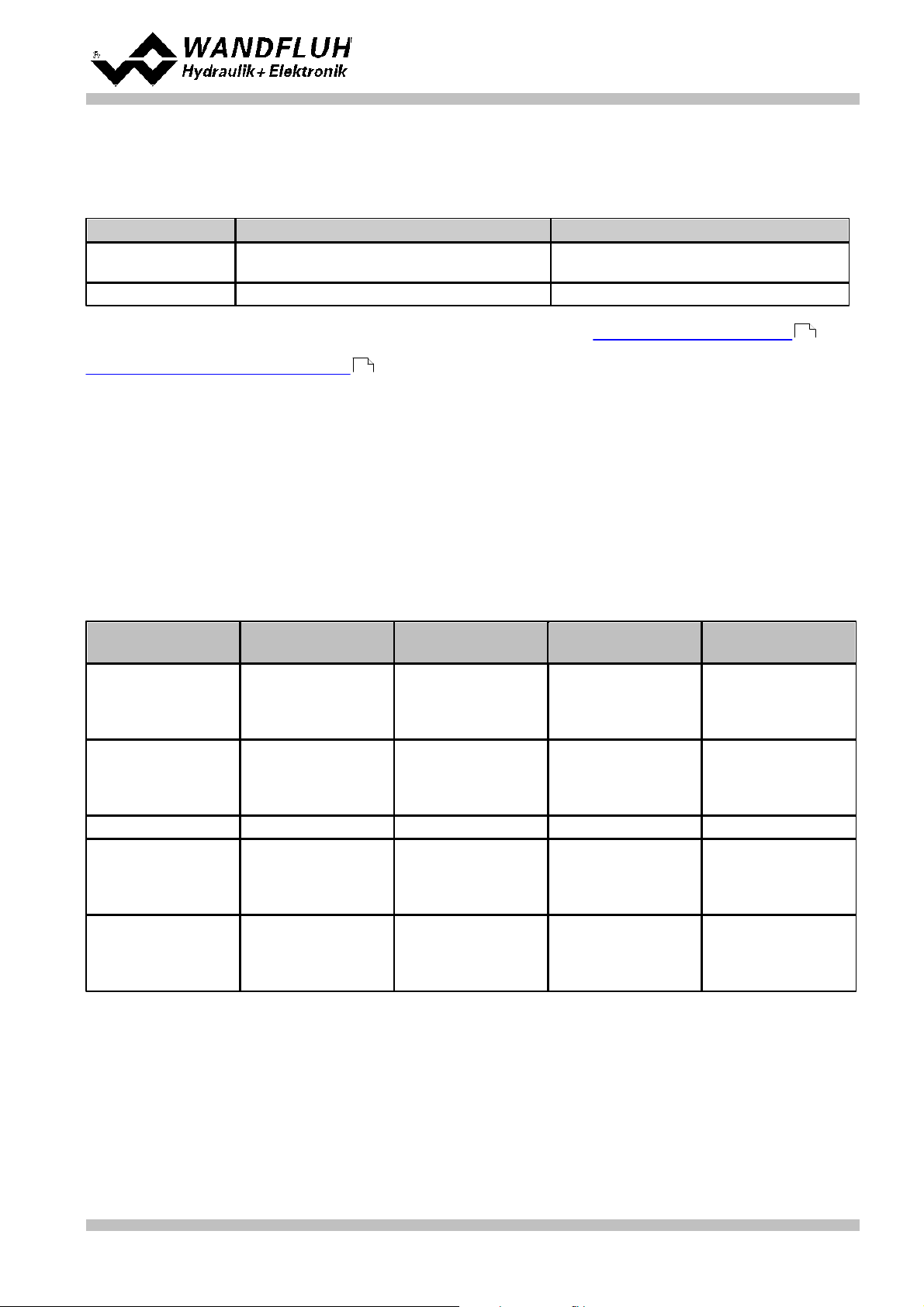
Function
· Amplifier
· Amplifier with manual operation
· Amplifier with fixed command values
· Basic Controller
· Enhanced Controller
Analogoutputs
· Input 1 voltage or current
· Input 2 voltage or current
· Input 2 current
only if Function = Enhanced Controller
· Input 3 voltage or current
· Input 4 voltage or current
Number of solenoids
· 1-Solenoid
· 2-Solenoid
Mode of operation
· without mode of operation 'Solenoid single' (only if Function = Amplifier)
· with mode of operation 'Solenoid single' (only if Function = Amplifier)
Fieldbus
· without Fieldbus
· with Profibus DP (only if Funciton = Amplfier, Basic Controller or Enhanced Controller)
7.5 File-Menu
Contained in the File menu are the menu points, which concern the file handling and the printing of the
parameters. In the "On Line"-mode, some of these menu points are blocked.
7.5.1 File_New
This menu point is active only in the "Off Line"-mode.
With this command, a new file can be opened. Near it, all parameters are set to default values. A question will be
displayed, if the current configuration will be retain or not.
If "Yes" will be selected, the current configuration will not be changed.
If "No" will be selected, a selection window will be displayed. In this window, the following configuration can be
selected.
The modified configuration only affects the "Off Line"-mode. By switching to "On Line"-mode the
configuration of the connected SD6-electronics will be read in.
7.5.2 File_Open
This menu point is only active in the "Off Line"-mode.
With this command, an existing file from a storage medium is opened. First the file selection window appears. In
this window the required file can now be selected and opened with ”OK”. If the configuration of the selected file
does not correspond to the current configuration of the PASO DSV/SD6, a message will be displayed and the
current configuration from the PASO DSV/SD6 will change automatically over to the new configuration of the
selected file. The read parameter values will be checked in the case of a limiting value excess. If one or more
parameter values are outside the tolerance, a message will be displayed and the parameter value will be set to
the default value (refer to section "Limiting value error" ). The parameter values can now be edited and
87
changed as required under the corresponding menu points.
7.5.3 File_Save
With this command, the parameters are saved on a data storage medium. All parameter values of all input
windows are saved under the current file name. If no file name has been defined yet, then first the file selection
window appears (refer to section "File_Save as..." ).
Wandfluh AG
Postfach
CH-3714 Frutigen
Tel: +41 33 672 72 72
Fax: +41 33 672 72 12
35
Email: sales@wandfluh.com
Internet: www.wandfluh.com
Page 34
Edition 12 14
SD636bae.pdf
Page 35

Operating instructions to Enhanced Controller module SD6
Date, time
Date, time of saving.
File name:
The file name, under which the file has been saved.
Valve type:
The valve type of the connected SD6-Electronics at the moment of saving. If no SD6-Electronics
are connected, then this indication remains empty. In case of saving during ”On Line Operation”,
this indication is updated.
Operator:
The name of the originating person.
Remarks:
Possibility to enter remarks concerning the file.
7.5.4 File_Save as
With this command, the parameters are saved on a data storage medium. All parameter values of all input
windows are saved under the file name entered.
First the file selection window appears. In this window the desired file name can now be entered. If the file name
is entered without an extension, then the extension ”.par” is automatically assigned to it. After actuating the key
”Save”, the file information window appears (refer to section "File-Info" ). In this window the required entries
35
can now be made. With the key ”Save”, the file is then finally saved under the selected file name. With the key
”Cancel”, one changes back to the file window.
7.5.5 File_Print
With this command, the current parameters are printed in ASCII text format. The File_Print window is opened. In
this window one can now select, whether the printing process is to be to a printer or to a file.
If the output is to be to a printer, then the Windows printer selection window is opened.. In this window, please
do not select ”Print to File”. If you do, a new program start might possibly be required and you could lose any
data not yet saved.
If the output is to be to a file, then the file selection window appears. In this window the desired file name can
now be entered. If the file name is entered without an extension, then automatically the extension ”.txt” is
assigned to it.
7.5.6 File_Info
With this command, the file information of an existing file is displayed. The file information consists of the
following parts:
When the File_Info window appears during the execution of the command ”File_Save”, then the corresponding
entries can be made in the various fields (with the exception of ”Date”, ”Time”, ”File name” and ”Card type”,
which cannot be edited). When the File_Info window appears during the execution of the command
”File_File-Info”, then the various fields cannot be edited.
7.5.7 File_Activate Off Line / Activate On Line
Off Line
With this command, the connection with the SD6-Electronics is interrupted. All menu points, which call for a
communication with the SD6-Electronics, are blocked. The PASO DSV/SD6 software now runs in the ”Off Line
mode”. The loading, saving and the editing of parameter files is possible in this mode.
On Line
With this command, the connection with the SD6-Electronics is established. The communication with the
SD6-Electronics is briefly tested. If the connection works, then the user has the option of taking over the
parameters from the SD6-Electronics or of transfering the parameters to the SD6-Electronics. During the
transfer of the parameters, the user has the possibility of aborting the operation.
Before parameters are transferred to the SD6-Electronics, a verification is carried out as to whether the
configuration of the SD6-Electronics supports the parameter values. The configuration corresponds here to the
number of the solenoids. If the configuration of the connected SD6-Electronics do not match with the current
configuration of the PASO DSV/SD6, a message will be displayed and the current configuration from the PASO
DSV/SD6 will change automatically over to the new configuration.
If the parameters have been taken over by the SD6-Electronics, then they will be checked in the case of a
limiting value excess. If one or more parameter values are outside the tolerance, a message will be displayed
and the parameter value will be set to the default value (refer to section "Limiting value error" ). The PASO
Wandfluh AG
Postfach
CH-3714 Frutigen
Tel: +41 33 672 72 72
Fax: +41 33 672 72 12
Email: sales@wandfluh.com
Internet: www.wandfluh.com
87
Page 35
Edition 12 14
SD636bae.pdf
Page 36

Operating instructions to Enhanced Controller module SD6
DSV/SD6 will stay in the "Off Line"-mode. For going On Line in this case, the parameter must be transferred to
the SD6-Electronics. If the transfer was successful and the limiting value check was also successful, then the
software subsequently runs in the "On Line"-mode. The loading of parameter files is not possible in this mode.
The current mode will be displayed in the status line.
7.5.8 File_SD6 datarecord info
This menu point is only active in the "On Line"-mode.
Under this menu the current data set information of the connected SD6-Electronics appears. The data
correspond to the last change to the SD6-Electronics data carried out.
7.5.9 File_Exit
With this command, the PASO DSV/SD6 is terminated. If parameter data have been changed and have not yet
been saved, then the question appears, as to whether these data should be saved. This is referring only to the
save in file. On the SD6-Electronics, the parameter will be saved automatically by clicking on the button "OK" in
the corresponding windows (refer to section "Store parameter" ).
87
Wandfluh AG
Postfach
CH-3714 Frutigen
Tel: +41 33 672 72 72
Fax: +41 33 672 72 12
Email: sales@wandfluh.com
Internet: www.wandfluh.com
Page 36
Edition 12 14
SD636bae.pdf
Page 37

Operating instructions to Enhanced Controller module SD6
· Command position (target - or end position of the sequence) xtarget
· Command speed value (command travelling speed of the process) vpreset
· Acceleration (acceleration or deceleration necessary for reaching the travelling speed, starting out from a
sequence start speed) as
· Deceleration (deceleration or acceleration necessary for reaching the sequence end speed) ds
· Stop time (possible dwell time after reaching the end position) ts
· Selection "Inside target window / End of Seq":
Digital output 2 is active, as soon as the sequence end is
reached and the sequence stop time is running. After
expiration of the the sequence stop, the output is inactive.
· Selection "Outside target window / Run of Seq
Digital output 2 ist active as long the sequence is running.
· Selection "Command =
Target":
Sequence end, if the command value has reached the command position
· Selection "Feedback =
Target":
Sequnce end, if the feedback value has reached the command position. The profile
generator waits to start a possible next to the sequence until the feedback valeu has
reached the target window. The timing of the target profile is therefore delayed by
the actual value.
7.6 Profile-Menu
The SD6-Electronics is in a position to save - and to run through complete travel profiles, which have been
predefined by the operator beforehand. A travel profile is a sequence of individual profiles (sequences), which
define a course of movement.
7.6.1 Sequence
A sequence consists of the travel command data and the stop time (dwell time after reaching the target position)
A sequence is defined by the operator with the help of the travel command data entered through the keyboard.
The travel command data contain:
With the controller mode "Alternating control (2-sol)" it is possible to adjust for each sequence a command
pressure. This command pressure is not part of the travel command data, but defines the maximum allowable
pressure. If the actual pressure will exceed the adjusted command pressure during run the sequence, the
pressure controller will be activated.
The travel command data of the sequences are saved in the EEPROM.
With the parameter "Sequence output" the selection can be made, if the state of the sequence should be
displayed on the digital output 2 or not.
Which state is displayed can be selected with the parameter "Digital output 2" (refer to section "
Configuration_Digital I/O ")
65
Mit dem Parameter "Sequenz Ende" kann die Sequenz- Ende Bedingung eingestellt werden:
Wandfluh AG
Postfach
CH-3714 Frutigen
Tel: +41 33 672 72 72
Fax: +41 33 672 72 12
Email: sales@wandfluh.com
Internet: www.wandfluh.com
Page 37
Edition 12 14
SD636bae.pdf
Page 38

Operating instructions to Enhanced Controller module SD6
Example "Command = Target"
Example "Feedback = Target"
· xstart (command position of the preceding sequence)
· xtarget (the command position entered)
· vstart (the starting speed of the sequence = target speed of the preceding sequence)
· vtarget (target speed when the command position is reached)
· The end of the profile has been reached
· vpreset of the next sequence is equal to zero (artificial profile end)
· A change of direction takes place at the end of the sequence
· A stop time ts greater than zero has been entered
Current sequence input value
deceleration
Next sequence input value
acceleration
vtarget, the target speed is
equated to
ds not equal to zero
as not equal to zero
vpreset of the next sequence
ds equal to zero
as not equal to zero
vpreset of the current sequence
ds not equal to zero
as equal to zero
vpreset of the next sequence
From the travel command data, the theoretical course of the sequence is calculated. The calculated course of
the sequence is jointly determined by the limit parameters (position and speed at the beginning and end of the
sequence) and it can significantly differ from the travel command data entered. Command positions and
possible stop times, however, are complied with in all cases.
The limit parameters are:
The target speed vtarget is determined by the operator input (travel command data) and the command speed
vpreset of the next sequence.
vtarget is equal to zero when:
In the other cases, vtarget is determined as follows from the operator input of acceleration as, deceleration ds
and command speed vpreset:
Wandfluh AG
Postfach
CH-3714 Frutigen
Tel: +41 33 672 72 72
Fax: +41 33 672 72 12
Email: sales@wandfluh.com
Internet: www.wandfluh.com
Page 38
Edition 12 14
SD636bae.pdf
Page 39

Operating instructions to Enhanced Controller module SD6
ds equal to zero
as equal to zero
vpreset of the next sequence
Digital input 6
Digital input 7
Digital input 8
Profile
000
0 (analogue command value)
100101021103001410150116111
7
Adaptation of the Acceleration or Deceleration to the Limit Parameters
In order for the target speed vtarget to be reached, the entered values for the acceleration as or deceleration ds
are adapted if necessary (e.g. reverse digit sign, i.e. acceleration becomes deceleration or vice versa, or if so
required change the value of the acceleration or deceleration). In conjunction with the other limit parameters, this
results in the calculated course of the sequence. The adapted values in contrast to the entered ones are not
saved in the EEPROM. They are only expressed in the graphic representation of the profile.
As a consequence of the physical limits of the axis control system, the calculated sequence course is possibly
not implementable. This is not verified by the Paso software.
7.6.2 Travel Profile
A travel profile as a minimum consists of one sequence and, as a maximum, of the maximum programmable
number of sequences. The sequences are consecutively numbered per travel profile (1..Maximum-Index). The
sequence number 1 serves to run up to the profile starting position. Because the starting position of this
sequence is not always known, this sequence is uniformly displayed in the graphic window with two blue arrows.
The travel profile ends either upon reaching the last sequence or else when reaching a sequence, which has
been programmed with the speed 0 (artificial profile end). Thereafter the following sequences are not carried out.
Per SD6-Electronics, a maximum of 50 sequences can be defined, which can be split-up in any manner required
over the maximum 7 profiles.
A movement profile can either be run through completely or else step-by-step (sequence by sequence). The
profile to be run through is selected through 3 digital inputs (= 7 profiles) (refer to section "Digital inputs" ).
13
The selection of the profiles is done by driving the digital inputs 6 - 8. It applies the following relationship:
With controller mode "Alternating control (2-soll)", note the following:
· in addition, the parameter "Command value position Signal type" must be set to "Profile" (refer to section
"Configuration_Signal scaling" ).
· if also the adjusted command pressure should be used, the parameter "Command value pressure Signal
type" must be set to "Profile" (refer to section "Configuration_Signal scaling" ).
· if the profile 0 is selected,
· wird das Fahrprofil 0 angewählt, no movement is performed (the external command value is not active)
Wandfluh AG
Postfach
CH-3714 Frutigen
53
Tel: +41 33 672 72 72
Fax: +41 33 672 72 12
53
Email: sales@wandfluh.com
Internet: www.wandfluh.com
Page 39
Edition 12 14
SD636bae.pdf
Page 40

Operating instructions to Enhanced Controller module SD6
With the help of the digital input digital input 4, the profile movement is started.
For every execution of a positioning, a start signal has to be applied. If the operating mode "Run through
individual sequence” has been selected (digital input 3 on "Low”), each sequence has to be started individually. If
in doing so, a stop time = 0 has been programmed, the corresponding sequences are combined into one
movement without any stopping time (sequence group).
In the operating mode "Run through complete profile” (digital input 3 to "High”), after the start signal the complete
profile is run through.
If a profile end is detected, then with the next start signal the processing starts again with the sequence 1. The
completion announcement of every completed travel profile is effected with the setting of the output signal
"Profile end”. The state of each sequence is effected with the digital output 2 (depends on the parameter
"Sequence output", refer to section "Profile Generator-Window ");
41
Any and all positioning operations can be stopped, if the digital input 5 "Stop” is activated (low active).
7.6.3 Example
Speed - Stroke Diagram:
Stroke - Time Diagram:
Wandfluh AG
Postfach
CH-3714 Frutigen
Tel: +41 33 672 72 72
Fax: +41 33 672 72 12
Email: sales@wandfluh.com
Internet: www.wandfluh.com
Page 40
Edition 12 14
SD636bae.pdf
Page 41

Operating instructions to Enhanced Controller module SD6
· The complete travel profile is indicated in black.
· The current sequence is indicated in blue (violet in the time diagram) and in boldface.
· The current sequence group is indicated in blue (violet).
· If at the end of the sequence a stop time has been defined, then this is indicated with a red cross.
· The 1st sequence is not indicated. It solely serves to predefine a defined starting position.
Field
Parameter description
Range / Step size
Profile Number
Here the number of the required profile can be selected.
1 .. 7
Profile End
Here the condition for setting the digital output 4 "Profile
End" can be selected:
- Profile end, if the command value has reached the
command position
- Profile end, if the feedback value has reached the
command position
Command = Target
Feedback = Target
Sequence Number
Here the number of the required sequence can be selected.
At the profile end (empty sequence), the delete-key is
deactivated. Browsing through the sequences is also
possible by means of the key combination CTRL + á or
CTRL + â
1 .. 50
Insert / delete
With these two keys, a sequence can be inserted into the
current profile or deleted from it.
Take over
With this key, the current values are taken over into the
current profile.
Command position
Predefinition of the end position.
Speed
Predefinition of the command speed.
0...max. speed
Travelling time
Travelling time of the current sequence excluding stop time,
only display. (Only appears in the stroke - time diagram)
Acceleration
Predefinition of the command acceleration.
0...max. acceleration
Deceleration
Predefinition of the command deceleration.
0...max. acceleration
Stop time
Predefinition of the stop time following a sequence end.
0...10sec
Sequence Output
Predefinition, whether the sequence output is to be
activated or not when the sequence end has been reached.
on / off
Sequence End
Here the condition for the sequence end can be selected
- Sequence end, if the command value has reached the
command position
- Sequence end, if the feedback value has reached the
command position
Command = Target
Feedback = Target
Sequence
travelling
Complete profile
If this input is activated, the commands „Home” and „Start”
7.6.4 Profile Generator Window
In the profile generator window, the parameters described above can be predefined.
When running through the profiles, however, because of the predefined values (speed and position) of adjacent
sequences it is possible, that the values entered into the fields acceleration and deceleration of the current
sequence cannot be complied with. These values in this case are adapted during the calculation of the
sequence.
In the display of the travel profiles, the following has to be noted:
By clicking on a sequence in the graphic window with the left-hand mouse button, it automatically becomes the
current sequence. The field „Sequence No.” is adapted accordingly.
In the graphic window, the current travel profile is displayed as a speed - stroke - or stroke - time diagram. The
changeover between the two types of diagram takes place by pushing the right-hand mouse button and selecting
the required type of diagram, or else with the key combination CTRL+D.
Attention: When leaving the window with the key „Cancel”, all data, which have not previously been
saved by means of the key „OK”, are lost!
Wandfluh AG
Postfach
CH-3714 Frutigen
Tel: +41 33 672 72 72
Fax: +41 33 672 72 12
Email: sales@wandfluh.com
Internet: www.wandfluh.com
Page 41
Edition 12 14
SD636bae.pdf
Page 42

Operating instructions to Enhanced Controller module SD6
Field
Parameter description
Range / Step size
refer to the current profile, if not, to the current sequence.
Home
The axis will move to the starting position of the current
sequence (or of the current profile, if the input „Complete
profile” is actuated).
Start
The current sequence (or current profile, if the input
„Complete profile” is activated) is run through. The „Start”
key can only be activated, if the „Home” key has been
actuated beforehand.
Direct operation
Drive enable
If this key is pushed, the commands of „Sequence
travelling” and „Direct operation” can be executed,
otherwise they are disabled.
Graphic window
· Changeover between the speed - stroke - and stroke time diagram by pushing the right-hand mouse button and
selection of the required type of diagram, or else with the
key combination CTRL+D.
· With the combination „CTRL+Left-hand mouse key”, the
graphic display is zoomed in, with the combination
„CTRL+Right-hand mouse key”, the graphic display is
zoomed out.
· With the combination „SHIFT+CTRL+Left-hand mouse
key”, the graphic display can be moved.
· By clicking on a sequence in the graphic window with the
left-hand mouse key, this sequence automatically
becomes the current sequence. The field „Sequence No.”
is accordingly adapted.
Wandfluh AG
Postfach
CH-3714 Frutigen
Tel: +41 33 672 72 72
Fax: +41 33 672 72 12
Email: sales@wandfluh.com
Internet: www.wandfluh.com
Page 42
Edition 12 14
SD636bae.pdf
Page 43

Operating instructions to Enhanced Controller module SD6
Field
Parameter description
Range / Step
Direct solenoid
operation
If this switch is selected, an internal command value from
0% resp. 100% will be active during the setting of the Imin
resp. Imax. If this switch is not selected, the external
command value will be active.
This command is only active in the "On Line"-mode
and if the operating mode is set to "Remote PASO".
Solenoid current
The minimum and the maximum solenoid current can be
set separately for each solenoid output, corresponding to
0% resp. 100% command value.
In the "Off Line"-mode, the displayed current value is the
theoretical command current. This makes it possible to set
the Imin/Imax values without a solenoid or a valve,
connected to the SD6-Electronics.
In the "On Line"-mode, if the Imin setting is active, a
command value of 0% resp. if the Imax setting is active, a
command value of 100% is automatically applied internally
(only if the switch "Direct solenoid operation" is selected).
As a result of the digitalisation, the numbers entered max
be modified to less "rounded-off" number.
Imin A
Set minimum solenoid current A.
(= solenoid current by 0% command value)
0 ... 950mA
1.8mA (24V-Version)
2.3mA (12V-Version)
Imax A
Set maximum solenoid current A.
(= solenoid current by 100% command value)
For the max. current refer to section "Electrical
specifications" .
Imin ... max. current
1.9mA (24V-Version)
2.3mA (12V-Version)
Imin B
(only 2-solenoid
version)
Set minimum solenoid current B.
(= solenoid current by 0% command value)
0 ... 950mA
1.9mA (24V-Version)
2.3mA (12V-Version)
Imax B
(only 2-solenoid
version)
Set maximum solenoid current B.
(= solenoid current by 100% command value)
For the max. current refer to section "Electrical
specifications"
Imin ... max. current
1.9mA (24V-Version)
2.3mA (12V-Version)
Frequency
The dither frequency can be set in steps.
2, 4, 6, 8, 10, 12, 14,
16, 18, 20, 25, 30, 35,
40, 45, 50, 55, 60, 70,
80, 100, 125, 165, 250,
500Hz
Level
Level of the superimposed dither signal
0 ... 399mA
3.8mA (24V-Version)
4.6mA (12V-Version)
Deadband
Command value < Deadband = 0 mA solenoid current
A
Command value >= Deadband = Imin .. Imax solenoid
current A
(Only Controller Mode 3 and 6)
0 ... 100%
0.1%
7.7 Parameters-Menu
In this window, all parameter values of the SD6-Electronics will be adjusted.
7.7.1 Parameters_Valves
In this window, all settings specific to the valves will be made. In the factory, the SD6-Electronics will be adjusted
to the valve. By changing the valves parameters, the valve characteristic is changed also. This has a
influence on the system response. With the menu item "Configuration_Default setting", the values set in the
factory can be reloaded at any time.
5
5
Wandfluh AG
Postfach
CH-3714 Frutigen
Tel: +41 33 672 72 72
Fax: +41 33 672 72 12
Email: sales@wandfluh.com
Internet: www.wandfluh.com
Page 43
Edition 12 14
SD636bae.pdf
Page 44

Operating instructions to Enhanced Controller module SD6
Solenoid current [I]
Imax
0
Preset value [%]
0 100
Deadband
Imin
Solenoid A
Deadband = 0%
Deadband = 10%
Solenoid current [I]
Imax
0
Preset value [%]
-100 100
Deadband
Imin
Solenoid A
Deadband = 0%
Deadband = 10%
Solenoid B
1-Solenoid version
2-Solenoid version
Wandfluh AG
Postfach
CH-3714 Frutigen
Tel: +41 33 672 72 72
Fax: +41 33 672 72 12
Email: sales@wandfluh.com
Internet: www.wandfluh.com
Page 44
Edition 12 14
SD636bae.pdf
Page 45

Operating instructions to Enhanced Controller module SD6
Index
X-Axis value
Y-Axis value
00010100
100
Characteristic optimisation:
This setting is available only with a SD6-electronics with software version higher than 1.1.1.6 and PASO with
software version higher than 1.5.0.9!
This menu enables the optimisation of the solenoid current adjustment of SD6-Electronics. A graphic is shown
which represents the characteristic “Preset value (X-axis) – Solenoid current (Y-axis)”. The graphic consists of
11 points, the first and the last point (100%) are preset.
The other graphic points can be adjusted either by tracking with the mouse or by entering the value at the
numeric inputs. The resolution of the X-values is in %, those of the Y-values in 0.1 %. The X-values cannot be
falling.
At shipping ex work (default settings) the preset value is transmitted proportionally to the solenoid current
(default characteristic). In this case the characteristic “Preset value (X-axis – Solenoid current (Y-axis)” is linear.
The same behaviour occurs at any time when the characteristic optimisation is turned off.
By modifying the default linear characteristic “Preset value (X-axis) – Solenoid current (Y-axis)” e.g. a progressiv
valve characteristic “Current - Flow/Pressure” can be compensated in such a way that a linear relation between
preset value and Flow / Pressure is realised. The characteristic “Preset value (X-axis) – Solenoid current
(Y-axis)” in this case should be adjusted in the “opposite progressive” direction (refer to the example
characteristic below).
Additionally the characteristic optimisation must be turned on. This will be shown in the PASO-Status line (refer
to section "Starting of PASO DSV/SD6" ).
86
The solenoid current values are in the range Imin (0%) up to Imax (100%). Imin and Imax are adjusted in the
Wandfluh AG
Postfach
CH-3714 Frutigen
Tel: +41 33 672 72 72
Fax: +41 33 672 72 12
Email: sales@wandfluh.com
Internet: www.wandfluh.com
Page 45
Edition 12 14
SD636bae.pdf
Page 46

Operating instructions to Enhanced Controller module SD6
Field
Parameter description
Range / Step size
Ramps
After a command value jump the new command value is
run-up to over a linear ramp (depending on the ramp time
set). For both solenoids separately a ramp time Up and a
ramp time Down can be set.
Ramp A Up
The ramp time set refers to a command value jump from
0% to 100% for the solenoid A.
0 ... 51s
0.05s
Ramp A Down
The ramp time set refers to a command value jump from
100% to 0% for the solenoid A.
0 ... 51s
0.05s
Ramp B Up
(only 2-solenoid
version)
The ramp time set refers to a command value jump from
0% to 100% for the solenoid B.
0 ... 51s
0.05s
Ramp B Down
(only 2-solenoid
version)
The ramp time set refers to a command value jump from
100% to 0% for the solenoid B.
0 ... 51s
0.05s
menu “Solenoid current”. At an input value which is between two graphic points, the solenoid current is
interpolated. If two or more preset values overlap, at the corresponding Preset value the highest current value is
calculated.
In the case of an error in the characteristic values, the characteristic optimisation is automatically turned off.
7.7.2 Parameters_Ramps
In this window all settings of the ramp function are made. The ramps can only be set in the controller mode
"Pressure/flow valve open loop" and "Position open loop". In all other controller modes the ramp settings
have no significance.
Wandfluh AG
Postfach
CH-3714 Frutigen
Tel: +41 33 672 72 72
Fax: +41 33 672 72 12
Email: sales@wandfluh.com
Internet: www.wandfluh.com
Page 46
Edition 12 14
SD636bae.pdf
Page 47

Operating instructions to Enhanced Controller module SD6
Feld
Parameter description
Range / step size
Speed+
After a positive command value jump the new command
value is run-up to over a linear ramp (depending on the
speed+ set). On the actuator this corresponds to a certain
travel speed.
0 ... 2000
Step size depends on
the scaling
Speed–
After a negative command value jump the new command
value is run-up to over a linear ramp (depending on the
speed– set). On the actuator this corresponds to a certain
travel speed.
0 ... 2000
Step size depends on
the scaling
Slow Speed
„Normal”-speed in manual operation.
0 ... 2000
Step size depends on
the scaling
Fast Speed
Rapid movement speed in manual operation.
0 ... 2000
Step size depends on
the scaling
HINT:
The limitation of speed can be disabled by entering the value 0. In this case, the command value
acts undelayed onto the solenoid(s).
7.7.3 Parameter_Command Value Generator
In this window all settings concerning the command value generator are made. The command value generator
can only be set in the controller modes "Pressure/flow valve closed loop (1-sol)", "Speed control closed
loop (2-sol), "Position closed loop (2-sol), "Pressure control closed loop (2-sol)", "pQ control (2-sol)"
and "Alternating control (2-sol). In all other controller modes, the command value generator settings have no
significance.
With the control mode "Alternating control (2-sol)", the parameters "Speed +" and "Speed -" can be set
separately for the position and pressure controller.
With the control mode "pQ control (2-sol)", the parameters "Speed +" and "Speed -" can be set only for the
pressure controller. For the open loop movement, the parameters "Ramp A up", "Ramp A down", "Ramp B up"
and "Ramp B down" are available (refer to section "Parameter_Ramps ").
46
Wandfluh AG
Postfach
CH-3714 Frutigen
Tel: +41 33 672 72 72
Fax: +41 33 672 72 12
Email: sales@wandfluh.com
Internet: www.wandfluh.com
Page 47
Edition 12 14
SD636bae.pdf
Page 48

Operating instructions to Enhanced Controller module SD6
Symmetrical setting
If this function is activated, the setting changes of a
controller block are also transferred to the other controller
block.
Command feed
forward
The command value is multiplied with this factor and added
to the correcting variable of the controller. If this factor is 0,
no command value proportion is added to the correcting
variable.
0 ... 10
0.1
Velocity feed forward
The change of the command value (the increase speed of
the command value) is multiplied with this factor and added
to the correcting variable of the controller. If this factor is 0,
no command value addition is added to the correcting
variable.
0 ... 10
0.1
I-term, if control
deviation >
I-window outside
I-term is set to 0 if control deviation is outside the outside
I-window.
I-term is held if control deviation is outside the outside
I-window.
set to 0
leave value
I-term, if controller is
not active
I-term is set to 0 if the corresponding controller is not active
I-term is held if the corresponding controller is not active
This parameter is only available with controller mode "pQ
control (2-sol)" and "Alternating control (2-sol)"
P-amplification
positive
P-amplification factor for positive control difference.
0 ... 25
0.1
I-window outside
positive
Defines the outside I-window. If the control difference is
within this window, the I-proportion is calculated with the set
I-time positive.
Adapted to unit
I-window inside
positive
Defines the inside I-window. If the control difference is within
this window, the I-proportion is freezed.
Adapted to unit
D-amplification
positive
D-amplification factor for positive control difference.
0 ... 10
I-time positive
Reaction time for the integrator. If the time is set to 0s, the
integrator is switched off.
0 ... 10s
0.01s
D-time positive
Defines the time window, how long after a positive set-point
value jump the D-controller is to be active.
0 ... 10s
0.1s
P-amplification
negative
P-amplification factor for negative control difference.
0 ... 25
0.1
I-window outside
negative
Defines the outside I-window. If the control difference is
within this window, the I-proportion is calculated with the set
I-time negative.
Adapted to unit
I-window inside
negative
Defines the inside I-window. If the control difference is within
this window, the I-proportion is freezed..
Adapted to unit
D-amplification
negative
D-amplification factor for negative control difference.
0 ... 10
I-time negative
Reaction time for the integrator. If the time is set to 0s, then
the integrator is switched off.
0 ... 10s
0.01s
D-time negative
Defines the time window, how long after a negative set-point
value jump the D-controller is to be active.
0 ... 10s
0.1s
7.7.4 Parameter_Controller
In this window all settings concerning the controller are made. The controller is split-up into two independent
blocks for positive and negative control difference. With this, asymmetrical characteristics of the hydraulic
system can be compensated for.
With the control mode "Alternating control (2-sol)", the parameters can be set separately for the position and
pressure controller.
With the control mode "pQ control (2-sol)", the parameters are only valid for the pressure controller.
Wandfluh AG
Postfach
CH-3714 Frutigen
Tel: +41 33 672 72 72
Fax: +41 33 672 72 12
Email: sales@wandfluh.com
Internet: www.wandfluh.com
Page 48
Edition 12 14
SD636bae.pdf
Page 49

Example with outside and inside I-window:
Block diagram of the controller:
Operating instructions to Enhanced Controller module SD6
Wandfluh AG
Postfach
CH-3714 Frutigen
Tel: +41 33 672 72 72
Fax: +41 33 672 72 12
Email: sales@wandfluh.com
Internet: www.wandfluh.com
Page 49
Edition 12 14
SD636bae.pdf
Page 50

7.7.5 Parameter_Window
Field
Parameter description
Range / step size
Target window
threshold
Defines the target window.
HINT: This signal is routed normal or invers to digital output
2 and it's state is displayed in the Analysis-Window of
PASO (refer to section "Analysis_Values" ).
Adapted to unit
Target window delay
time
Delay time when falling below and exceeding the target
window threshold.
0 ... 100ms
1ms
Trailing error window
threshold
Defines the trailing window.
HINT: This signal is routed normal or invers to digital output
3 and it's state is displayed in the Analysis-Window of
PASO (refer to section "Analysis_Values" ).
Adapted to unit
Trailing error window
delay time
Delay time when falling below and exceeding the target
window threshold.
0 ... 100ms
1ms
Solenoid-off window
threshold
Defines the solenoid-off window. If the control difference is
within this window, the solenoid outputs are switched off.
Adapted to unit
Solenoid-off window
delay time
Delay time when falling below and exceeding the
solenoid-off window threshold.
0 ... 100ms
1ms
Operating instructions to Enhanced Controller module SD6
74
74
Target window::
Wandfluh AG
Postfach
CH-3714 Frutigen
Tel: +41 33 672 72 72
Fax: +41 33 672 72 12
Email: sales@wandfluh.com
Internet: www.wandfluh.com
Page 50
Edition 12 14
SD636bae.pdf
Page 51

Trailing error window:
Solenoid-off window:
Operating instructions to Enhanced Controller module SD6
Wandfluh AG
Postfach
CH-3714 Frutigen
Tel: +41 33 672 72 72
Fax: +41 33 672 72 12
Email: sales@wandfluh.com
Internet: www.wandfluh.com
Page 51
Edition 12 14
SD636bae.pdf
Page 52

Operating instructions to Enhanced Controller module SD6
Field
Parameter description
Range / step size
Controller mode
Select the desired controller mode (refer to
section "Controller modes" ).
Depending on the selected controller mode it
is possible that other parameters are
adjusted automatically.
Pressure/flow valve open loop = 3
Pressure/flow valve closed loop (1-sol) =
4
Position open loop = 6
Speed control closed loop (2-sol) = 7
Position control closed loop (2-sol) = 9
Pressure control closed loop (2-sol) = –5
pQ control (2-sol) = –9
Alternating control (2-sol) = –10
Output solenoid A
Solenoid output A can be inverted. Cannot be
selected with the controller modes 6 and 9.
inverted
not inverted
Output solenoid B
Solenoid output B can be inverted. Cannot be
selected with the controller modes 6 and 9.
inverted
not inverted
System control
sense
With this function the solenoid outputs can be
interchanged. With solenoid current A the
solenoid output B is driven and with solenoid
current B the solenoid output A is driven
inverted
not inverted
Solenoid 'In
Position'
off: Solenoids are switched off, when the
solenoid-off window is reached.
on: Solenoids are not switched off, even
when the solenoid-off window is reached
(refer to section "Parameter_Window" )
off
on
Imin always active
(Position)
If this function is activated, then the solenoid
current is never less than Imin.
With the control mode "Alternating control
(2-sol)", this parameter effects to the position
controller
no
yes
Imin always active
(Pressure)
If this function is activated, then the solenoid
current is never less than Imin.
With the control mode "Alternating control
(2-sol)", this parameter effects to the
pressure controller
no
yes
Field
Parameter description
Range / step size
Operating mode
Select the required operating mode (refer to
section "Mode of Operation" ).
Depending on the selected operating mode it may
be, that the signal type is automatically adapted.
Command value unipolar (1-sol)
Command value unipolar (2-sol)
Command value bipolar (2-sol)
Command value unipolar (2-sol,
selectable by digital input)
7.8 Configuration-Menu
In this window, the settings of the function of the SD6-Electronics will be made.
7.8.1 Configuration_Controller mode
In this window the configuration for the controller is made. Depending on the selected controller mode not all
parameters can be adjusted.
15
50
7.8.2 Configuration_Mode of operation
This menu point is only active in the SD6-state "Disabled" (refer to section "SD6 State Machine" ).
11
In this window the operating mode of the SD6-Electronics is set. The operating mode can only be selected in
case of controller mode "Pressure/flow valve open loop", "Position open loop", "Speed control closed loop
(2-sol)" and "pQ control (2-sol)", in case of all other controller modes the operating mode has no significance.
52
Wandfluh AG
Postfach
CH-3714 Frutigen
Tel: +41 33 672 72 72
Fax: +41 33 672 72 12
Email: sales@wandfluh.com
Internet: www.wandfluh.com
Page 52
Edition 12 14
SD636bae.pdf
Page 53

7.8.3 Configuration_Signal scaling
Field
Parameter description
Range / step size
Configuration
In this range the configuration of the command signal is done
Signal type
In this field the required signal type can be selected.
The signal type "+/-10 VDC" can only be selected in the controller
mode "Pressure/flow valve open loop", "Position open loop", and
"pQ control (2-sol)" and operating mode "Command value bipolar
(2-sol)" (refer to section "Configuration_Mode of operation ").
The signal type "Profile" can only be selected in the controller
mode "Alternating control (2-sol).
0...10 VDC
+/-10 VDC
0...20 mA
4...20 mA
Profile
Input used
Depending on the SD6 type different voltage resp.current inputs
are available (refer to chapter "Technical specifications ").
The appropriate input for the selected signal type is automatically
set.
Different input for command and feedback signal should be used.
AnaInp1 [V]
AnaInp2 [mA]
AnaInp3 [V]
AnaInp4 [mA]
Inversion
The analogue value read-in can be inverted (refer to the figure
below).
The command value input can only be inverted in the controller
mode "Pressure/flow valve open loop" and "Position open loop".
no
yes
Cable break
Switching-on/-off of the cable break detection of the analogue
input signals (refer to section "Cable-break detection" ).
no
yes
Scaling
In this range the scaling of the command signal is done. The
scaling depends on the selected controller mode:
Operating instructions to Enhanced Controller module SD6
This menu point is only active in the SD6-state "Disabled" (refer to section "SD6 State Machine" ).
11
In this window the settings and the scaling of the command value - and feedback value signal is made.
ATTENTION:
With controller mode "pQ control" and "Alternating control" the dependencies of the inputs must be
53
respected!
Command value resp. Command value position (with controller mode "pQ control" and "Alternating
control"):
52
5
Wandfluh AG
Postfach
CH-3714 Frutigen
Tel: +41 33 672 72 72
Fax: +41 33 672 72 12
13
Email: sales@wandfluh.com
Internet: www.wandfluh.com
Page 53
Edition 12 14
SD636bae.pdf
Page 54

Operating instructions to Enhanced Controller module SD6
Field
Parameter description
Range / step size
Scaling
With this parameter it is defined, by how many percent the
command value is to change in case of a change of 1V, resp.
1mA at the analogue input (= gradient).
If the signal type is changed, then the parameter scaling is
automatically set to the corresponding default value (refer to
table below).
Attention: If the scaling does not correspond to the default
value, the resolution is < 10-bit resp. < 16-bit!
This parameter can only be set in case of an open loop controller
modes
0.001 ... 100.000%
0.001%
Offset
With this parameter the zero point of the analogue signal is set
(refer to the figure below).
Depending on the signal type, the setting is in V or mA.
Voltage:
Current:
This parameter can only be set in case of an open loop controller
modes
0 ... ±10.00V
0.01V
0 ... ±20.00mA
0.02mA
min interface
Indicates the command A/D value in case of "min Reference
commandvalue" (refer to the figure below).
Voltage:
Current:
This parameter can only be set in case of an closed loop
controller modes.
0 ... 10.00V
0.01V
0 ... 20.00mA
0.02mA
max interface
Indicates the command A/D value in case of "max Reference
command value" (refer to the figure below).
Voltage:
Current:
This parameter can only be set in case of an closed loop
controller modes.
0 ... 10.00V
0.01V
0 ... 20.00mA
0.02mA
min reference
Indicates the absolute command value measured value in a
freely selected measuring point (refer to the figure below).
The min reference command value has to be smaller than the
max reference command value.
This parameter can only be set in case of an closed loop
controller modes..
Dependent on unit
max reference
Indicates the absolute command value measured value in a
freely selected measuring point (refer to the figure below)..
The max reference command value has to be higher than the
min reference command value.
This parameter can only be set in case of an closed loop
controller modes..
Dependent on unit
Wandfluh AG
Postfach
CH-3714 Frutigen
Tel: +41 33 672 72 72
Fax: +41 33 672 72 12
Email: sales@wandfluh.com
Internet: www.wandfluh.com
Page 54
Edition 12 14
SD636bae.pdf
Page 55

Operating instructions to Enhanced Controller module SD6
Field
Parameter description
Range / step size
Configuration
In this range the configuration of the feedback signal is done
Signal type
In this field the required signal type can be selected.
0...10 VDC
+/-10VDC
0...20 mA
4...20 mA
SSI-Gray
SSI-Binary
Start/Stop
Input used
Depending on the SD6 type different voltage resp.current inputs
are available (refer to chapter "Technical specifications ").
The appropriate input for the selected signal type is
automatically set.
Different input for command and feedback signal should be
used
AnaInp1 [V]
AnaInp2 [mA]
AnaInp3 [V]
AnaInp4 [mA
DigSens [X3]
Cablebreak
detection
Switching-on/-off the cable break detection of the analogue
input signals (refer to section "Cablebreak detection ").
no
yes
Scaling
In this range the scaling of the feedback signal is done.
min interface
Indicates the command A/D value in case of "min Reference
commandvalue" (refer to the figure below).
This parameter is only relevant if the used input is set to
AnaInp1, AnaInp2, AnaInp3 or AnaInp4.
Voltage:
Current:
0 ... 10.00V
0.01V
0 ... 20.00mA
0.02mA
max interface
Indicates the command A/D value in case of "max Reference
commandvalue" (refer to the figure below).
This parameter is only relevant if the used input is set to
AnaInp1, AnaInp2, AnaInp3 or AnaInp4.
Voltage:
Current:
0 ... 10.00V
0.01V
0 ... 20.00mA
0.02mA
min reference
Indicates the absolute feedback value measured in a freely
selectable measuring point (refer to figure below).
The min reference feedback value has to be smaller than the
max reference feedback value.
This parameter is only relevant if the used input is set to
AnaInp1, AnaInp2, AnaInp3 or AnaInp4.
Dependent on unit
Feedback value resp. Feedback value position (with controller mode "pQ control" and "Alternating
control"):
These parameters are only adjustable with controller modes "Pressure/flow valve closed loop (1-sol)", "Speed
control closed loop (2-sol)", "Position control closed loop (2-sol)", "Pressure control closed loop (2-sol)" and
"Alternating control (2-sol)"
5
13
Wandfluh AG
Postfach
CH-3714 Frutigen
Tel: +41 33 672 72 72
Fax: +41 33 672 72 12
Email: sales@wandfluh.com
Internet: www.wandfluh.com
Page 55
Edition 12 14
SD636bae.pdf
Page 56

Operating instructions to Enhanced Controller module SD6
Field
Parameter description
Range / step size
max reference
Indicates the absolute feedback value measured in a freely
selectable measuring point (refer to figure below).
The max reference feedback value has to be higher than the
min reference feedback value.
If the used input is to DigSens [X3], this value should
correspond to the maximum possible stroke of the cylinder.
Dependent on unit
Offset
Indicates the offset of the digital measuring system. This
parameter is only relevant if the used input is set to DigSens
[X3].
Dependent on unit
Resolution
Indicated the resolution of the digital measuring system. This
parameter is only relevant if the signal type is set to SSI-Gray or
SSI-Binary.
unit / inc
Bit number
Indicates the number of bits of the digital measuring system.
This parameter is only relevant if the signal type is set to
SSI-Gray or SSI-Binary.
v-propagation
Indicates the propagation speed of the digital measuring
system. This parameter is only relevant if the signal type is set
to Start/Stop.
unit / s
Field
Parameter description
Range / step size
Configuration
In this range the configuration of the command signal is done
Signal type
In this field the required signal type can be selected.
The signal type "+/-10 VDC" can only be selected in the
controller mode "Pressure/flow valve open loop", "Position
open loop", and "pQ control (2-sol)" and operating mode
"Command value bipolar (2-sol)" (refer to section "
Configuration_Mode of operation ").
The signal type "Profile" can only be selected in the parameter
"Signal type position" is set also to "Profile"
0...10 VDC
+/-10 VDC
0...20 mA
4...20 mA
Profile
Input used
Depending on the SD6 type different voltage resp.current
inputs are available (refer to chapter "Technical specifications
").
The appropriate input for the selected signal type is
automatically set.
Different input for command and feedback signal should be
used.
AnaInp1 [V]
AnaInp2 [mA]
AnaInp3 [V]
AnaInp4 [mA]
Cable break
Switching-on/-off of the cable break detection of the analogue
input signals (refer to section "Cable-break detection" ).
no
yes
Scaling
In this range the scaling of the command signal is done.
min interface
Indicates the command A/D value in case of "min Reference
commandvalue".
Voltage:
Current:
0 ... 10.00V
0.01V
0 ... 20.00mA
0.02mA
max interface
Indicates the command A/D value in case of "max Reference
command value.
Voltage:
0 ... 10.00V
Command value pressure (only with controller mode "pQ control" and "Alternating control"):
52
5
13
Wandfluh AG
Postfach
CH-3714 Frutigen
Tel: +41 33 672 72 72
Fax: +41 33 672 72 12
Email: sales@wandfluh.com
Internet: www.wandfluh.com
Page 56
Edition 12 14
SD636bae.pdf
Page 57

Operating instructions to Enhanced Controller module SD6
Field
Parameter description
Range / step size
Current:
0.01V
0 ... 20.00mA
0.02mA
min reference
Indicates the absolute command value measured value in a
freely selected measuring point (refer to the figure below).
The min reference command value has to be smaller than the
max reference command value.
Dependent on unit
max reference
Indicates the absolute command value measured value in a
freely selected measuring point (refer to the figure below)..
The max reference command value has to be higher than the
min reference command value.
Dependent on unit
Field
Parameter description
Range / step size
Option
In this range the type of the connected pressure sensor is
selected
Sensor type
The pressure feedback signal is comming from a pressure
or force sensor with an absolute signal (V or mA)
The pressure feedback signal is built as a differential signal
from two pressure or force sensors (V or mA)
Absolute signal (1 sensor)
Differential pressure (2
sensors)
Configuration
sensor 1
In this range the configuration of the feedback signal from
sensor 1 is done
Signal type
In this field the required signal type can be selected.
0...10 VDC
+/-10VDC
0...20 mA
4...20 mA
Input used
Depending on the SD6 type different voltage resp.current
inputs are available (refer to chapter "Technical
specifications ").
The appropriate input for the selected signal type is
automatically set.
Different input for command and feedback signal should be
used
AnaInp1 [V]
AnaInp2 [mA]
AnaInp3 [V]
AnaInp4 [mA
Cablebreak
detection
Switching-on/-off the cable break detection of the analogue
input signals (refer to section "Cablebreak detection ").
no
yes
Scaling sensor 1
In this range the scaling of the feedback signal from sensor
1 is done.
min interface
Indicates the command A/D value in case of "min
Reference commandvalue" (refer to the figure below).
Voltage:
Current:
0 ... 10.00V
0.01V
0 ... 20.00mA
0.02mA
max interface
Indicates the command A/D value in case of "max
Reference commandvalue" (refer to the figure below).
Voltage:
Current:
0 ... 10.00V
0.01V
0 ... 20.00mA
0.02mA
Feedback value pressure (only with controller mode "pQ control" and "Alternating control"):
5
Wandfluh AG
Postfach
CH-3714 Frutigen
Tel: +41 33 672 72 72
Fax: +41 33 672 72 12
13
Email: sales@wandfluh.com
Internet: www.wandfluh.com
Page 57
Edition 12 14
SD636bae.pdf
Page 58

Operating instructions to Enhanced Controller module SD6
Field
Parameter description
Range / step size
min reference
Indicates the absolute feedback value measured in a freely
selectable measuring point (refer to figure below).
The min reference feedback value has to be smaller than
the max reference feedback value.
Dependent on unit
max reference
Indicates the absolute feedback value measured in a freely
selectable measuring point (refer to figure below).
The max reference feedback value has to be higher than
the min reference feedback value.
Dependent on unit
Scaling sensor 2
In this range the scaling of the feedback signal from sensor
1 is done. This range is only active, if the parameter
"Sensor type" is set to "Differential pressure (2 sensors)".
min interface
Indicates the command A/D value in case of "min
Reference commandvalue" (refer to the figure below).
Voltage:
Current:
0 ... 10.00V
0.01V
0 ... 20.00mA
0.02mA
max interface
Indicates the command A/D value in case of "max
Reference commandvalue" (refer to the figure below).
Voltage:
Current:
0 ... 10.00V
0.01V
0 ... 20.00mA
0.02mA
min reference
Indicates the absolute feedback value measured in a freely
selectable measuring point (refer to figure below).
The min reference feedback value has to be smaller than
the max reference feedback value.
Dependent on unit
max reference
Indicates the absolute feedback value measured in a freely
selectable measuring point (refer to figure below).
The max reference feedback value has to be higher than
the min reference feedback value.
Dependent on unit
Field
Parameter description
Range / step size
Display unit
In this field the required unit can be selected.
Controller mode pressure/flow control:
Controller mode speed control:
Controller mode position control:
All controller modes:
With controller modes "Alternating control", the displayed
unit can be set separately for the position and pressure
controller.
bar, psi, kN, MPa
l/min, mm/s, 1/Min,
inch/s, deg/s
mm, deg, inch
Own unit
Own unit
If with "Display unit" the type "Own unit" was selected, then
an own unit can be entered in this field.
Min. number of characters: 1
Max. number of characters: 5
General:
Wandfluh AG
Postfach
CH-3714 Frutigen
Tel: +41 33 672 72 72
Fax: +41 33 672 72 12
Email: sales@wandfluh.com
Internet: www.wandfluh.com
Page 58
Edition 12 14
SD636bae.pdf
Page 59

Operating instructions to Enhanced Controller module SD6
Preset value [%]
+100
-100
Analog input [V/mA]
-10V
0V
0mA
4mA
+10V
+10V
20mA
20mA
Scaling
Offset+-
Inversion = yes Inversion = no
Solenoid A
Solenoid B
0
Dependencies of the inputs
With controller mode "pQ-control" and "Alternating control", the following dependencies of the inputs have to be
considered:
· Because the SD6 card has only 4 analogue inputs, the parameter "Sensor type" can only be set to "Differential
pressure (2 sensors)" if either
- the parameter "Command value position - Signal type" = "Profile" or
- the parameter "Feedback value position - Signal type" = "SSI-Gray", "SSI-Binary" or "Start/Stop" or
- the position command value is specified via fieldbus (object "Device Mode" = "1") or
- the pressure command value is specified via fieldbus (object "Device Mode Pressure" = "1") or
· The parameter "Command value pressure - Signal type" can only be set to "Profile" if
- the parameter "Command value position - Signal type" is also set to "Profile"
· The parameter "Command value position - Signaltyp" can only be set to "0...10 VDC", "+/-10VDC", "0...20 mA"
or "4...20 mA" if
- the parameter "Command value pressure - Signal type" is not set to "Profile"
Controller mode "Pressure/flow valve open loop", "Position open loop", and "pQ control (2-sol)" (for the
Q command):
2-solenoid version
Examples:
Wandfluh AG
Postfach
CH-3714 Frutigen
Tel: +41 33 672 72 72
Fax: +41 33 672 72 12
Email: sales@wandfluh.com
Internet: www.wandfluh.com
Page 59
Edition 12 14
SD636bae.pdf
Page 60

Operating instructions to Enhanced Controller module SD6
Used analogue signal:
4 ... 20 mA
Command-Zero:
(4 mA + 20 mA) / 2 = 12 mA (middle of signal)
Selected signal type:
4 ... 20 mA
Standard Command-Zero:
12 mA (middle of signal)
Adjustment offset:
12 mA - 12 mA = 0 mA
Signal working range:
20 mA - 4 mA = 16 mA
Signal range per solenoid:
8 mA (= Signal working range / 2)
Adjustment Scaling:
100 % / 8 mA = 12.5 %/mA
Used analogue signal:
1.0 ... 8.0 V
Command-Zero:
(1.0 V + 8.0 V) / 2 = 4.5 V (middle of signal)
Selected signal type:
0 ... 10 V
Standard Command-Zero:
5 V (middle of signal)
Adjustment offset:
4.5 V - 5 V = -0.5 V
Signal working range:
8.0 V - 1.0 V = 7.0 V
Signal range per solenoid:
3.5 V (= Signal working range / 2)
Adjustment scaling:
100 % / 3.5 V = 28.57 %/V
Used analogue signal:
-9.0 ... +9.0 V
Command-Zero:
(-9.0 V + 9.0 V) / 2 = 0.0 V (middle of signal)
Selected signal type:
+/-10 V
Standard Command-Zero:
0.0 V (middle of signal)
Adjustment offset:
0.0 V - 0.0 V = 0.0 V
Signal working range:
9.0 V - (-9.0 V) = 18.0 V
Signal range per solenoid:
9.0 V (= Signal working range / 2)
Adjusment scaling:
100 % / 9.0 V = 11.11 %/V
Preset value [%]
+100
0 Analogi input [V/mA]
0V
0mA
4mA
+10V
20mA
20mA
Scaling
Offset
+-
Inversion = yes
Inversion = no
Solenoid A
Used analogue signal:
4 ... 20 mA
Command-Zero at:
4 mA
Selected signal type:
4 ... 20 mA
Standard Command-Zero at:
4 mA
Adjustment offset:
4 mA - 4 mA = 0 mA
Signal working range:
20 mA - 4 mA = 16 mA
Signal range per solenoid:
16 mA (= Signal working range)
Setting scaling:
100 % / 16 mA = 6.25 %/mA
1-solenoid version
Examples:
Wandfluh AG
Postfach
CH-3714 Frutigen
Tel: +41 33 672 72 72
Fax: +41 33 672 72 12
Email: sales@wandfluh.com
Internet: www.wandfluh.com
Page 60
Edition 12 14
SD636bae.pdf
Page 61

Used analogue signal:
2.0 ... 9.0 V
Command-Zero at:
2.0 V
Selected signal type:
0 ... 10 V
Standard Command-Zero at:
0.0 V
Adjustment offset:
2.0 V - 0.0 V = 2.0 V
Signal working range:
9.0 V - 2.0 V = 7 V
Signal range per solenoid:
7.0 V (= Signal working range)
Setting scaling:
100 % / 7.0 V = 14.29 %/V
Default - values of the parameter "Scaling"
Signal type
Operating mode
0 ... 10 VDC
+/-10 VDC
0 ... 20 mA
4 ... 20 mA
Command value unipolar (1-sol)
10 %/V
--
5 %/mA
6.25 %/mA
Command value unipolar (2-sol)
20 %/V
--
10 %/mA
12.5 %/mA
Command value bipolar (2-sol)
--
10 %/V----
Command value unipolar (2-sol
single)
10 %/V
--
5%/mA
6.25%/mA
Operating instructions to Enhanced Controller module SD6
Wandfluh AG
Postfach
CH-3714 Frutigen
Tel: +41 33 672 72 72
Fax: +41 33 672 72 12
Email: sales@wandfluh.com
Internet: www.wandfluh.com
Page 61
Edition 12 14
SD636bae.pdf
Page 62

Operating instructions to Enhanced Controller module SD6
Scaling point 1:
Min. Reference
=
0mm
Min. Interface
=0VScaling point 2:
Max. Reference
=
100mm
Max. Interface
=
10V
Scaling point 1:
Min. Reference
=
0mm
Min. Interface
=
4mA
Scaling point 2:
Max. Reference
=
100mm
Max. Interface
=
20mA
Controller mode "Pressure/flow valve closed loop (1-sol)", "Speed control closed loop (2-sol)", "Position
control closed loop (2-sol)", "Pressure control closed loop (2-sol)", "pQ control" (for p command) and
"Alternating control (2-sol)":
In controller mode 4, 7 and 9 the scaling is not set by means of gain and offset, but defined with two points.
These points in the following are called scaling points. A scaling point consists of a reference value and an
interface value.
Reference corresponds to the measuring value. In the following examples, the measuring value is a length.
Interface corresponds to the analogue signal.
It is advisable to select the two scaling points as far apart from one another as possible. Attention has to be paid,
that Min. Reference always has to be smaller than Max. Reference
Command value scaling:
In case of the command value normally the interface range and the reference range are known. From this two
scaling points can be decided on without any measuring.
1st Example:
An external control system presets the command value in the form of a voltage signal (0 ... 10V). At 0V the
position 0mm, and at 10V the position 100mm shall be run-up to.
2nd Example:
An external control system presets the command value in the form of a current signal (4 ... 20mA). At 4mA the
position 0mm, and at 20mA the position 100mm shall be run-up to.
Wandfluh AG
Postfach
CH-3714 Frutigen
Tel: +41 33 672 72 72
Fax: +41 33 672 72 12
Email: sales@wandfluh.com
Internet: www.wandfluh.com
Page 62
Edition 12 14
SD636bae.pdf
Page 63

Operating instructions to Enhanced Controller module SD6
10V
20mA
Interface
Reference [mm]
0
2
1
100
50-50
3
4
0V
0mA
SP1
SP2
SP2
SP2
SP1
SP1
SP1
Feedback value scaling:
By means of direct solenoid actuation (chapter "Commands_Valve actuation" page 41) run-up to a position.
1.
Measure the position (® Reference value).
2.
Measure the signal value of the feedback value sensor or select it by means of PASO (® Interface value).
3.
In this manner define two differing scaling points.
4.
The following illustration shows various examples for the scaling. In feedback practice, the command value and
the feedback value can be scaled differently.
Wandfluh AG
Postfach
CH-3714 Frutigen
Tel: +41 33 672 72 72
Fax: +41 33 672 72 12
Email: sales@wandfluh.com
Internet: www.wandfluh.com
Page 63
Edition 12 14
SD636bae.pdf
Page 64

Operating instructions to Enhanced Controller module SD6
Scaling point 1:
Min. Reference
=
0mm
Min. Interface
=
0V or 0mA
Scaling point 2:
Max. Reference
=
100mm
Max. Interface
=
10V or 20mA
Scaling point 1:
Min. Reference
=
0mm
Min. Interface
=
03.33V or 6.67mA
Scaling point 2:
Max. Reference
=
50mm
Max. Interface
=
10V or 20mA
Scaling point 1:
Min. Reference
=
25mm
Min. Interface
=
7.5V or 15mA
Scaling point 2:
Max. Reference
=
75mm
Max. Interface
=
2.5V or 5mA
Scaling point 1:
Min. Reference
=
25mm
Min. Interface
=
10V or 20mA
Scaling point 2:
Max. Reference
=
87.5mm
Max. Interface
=
0V or 0mA
•
‚
This example shows, that with positive interface values also negative reference values can be achieved.
ƒ
This example shows, that the scaling points do not necessarily have to be the end points.
„
This example shows, that depending on the scaling 0mm are never reached.
Wandfluh AG
Postfach
CH-3714 Frutigen
Tel: +41 33 672 72 72
Fax: +41 33 672 72 12
Email: sales@wandfluh.com
Internet: www.wandfluh.com
Page 64
Edition 12 14
SD636bae.pdf
Page 65

Operating instructions to Enhanced Controller module SD6
Field
Parameter description
Range / Step
* Signal
This determines which signal is to be performed on the output
(depending on the selected controller mode, different signals
are available)
- command value for the solenoid driver
- scaled command value
- scaled feedback value (only in closed loop modes 4, 7, 9)
- scaled control deviation (only in closed loop modes 4, 7, 9)
Control value
Command value
Feedback value
Control deviation
Min.interface
This parameter sets the minimal output voltage.
-10...+10V
0.01V
Max.interface
This parameter sets the maximal output voltage.
-10...+10V
0.01V
* Min. reference
With this signal, the value from Min. interface is issued
depending on the
parameter "Signal"
* Max. reference
With this signal, the value from Max. interface is issued
depending on the
parameter "Signal"
Field
Parameter description
Range / step size
Digital inputs
Reset digital input by software
Set digital input by software
Activate external digital input
Off
On
External
Digital output 1
Reset digital output with software
Set digital output with software
- Set in case of an error
- * Set in case of no error
Off
On
Error
Ready
Digital output 2
Reset digital output with software
Set digital output with software
Controller mode "Pressure/flow valve open loop"
and "Position open loop":
The digital output shows, if
- Solenoid B is active
- * Solenoid B is not active
Controller mode "Pressure/flow valve closed loop",
"Speed control closed loop", "Position control
closed loop" and "Pressure control closed loop
2-sol":
The digital output shows, if
- Target window reached
(when operating without profiles)
- a sequence is finished
(when operating with profiles,
refer to section "Profile-Menu_Sequence ")
Off
On
7.8.4 Configuration_Analog Output
In this window the scaling of the analog output can be set.
The signal at the analog output corresponds to the controller output (controller variable), and can be used for
driving a valve with integrated electronics which has a +/-10V interface.
* This setting is available only with a SD6-electronics with software version > 1.1.1.6 and PASO with software
version > 1.5.0.9!
7.8.5 Configuration_Digital IO
With this command, the digital inputs and ouputs (refer to section "Digital inputs" and "Outputs" ) of the
connected SD6-Electronics can be set to active, not active or released.
13 15
Wandfluh AG
Postfach
CH-3714 Frutigen
Tel: +41 33 672 72 72
Fax: +41 33 672 72 12
37
Email: sales@wandfluh.com
Internet: www.wandfluh.com
Page 65
Edition 12 14
SD636bae.pdf
Page 66

Operating instructions to Enhanced Controller module SD6
Field
Parameter description
Range / step size
- * Target window not reached
(when operating without profiles)
- * a sequence is running
(when operating with profiles,
refer to section "Profile-Menu_Sequence ")
Controller mode "pQ control" and "Alternating
control":
The digital output shows, if
- Position target window reached
(when operating without profiles)
- a sequence is finished
(when operating with profiles,
refer to section "Profile-Menu_Sequence ")
- * Position target window not reached
(when operating without profiles)
- * a sequence is running
(when operating with profiles,
refer to section "Profile-Menu_Sequence ")
- Pressure target window reached
- * Pressure target window not reached
- Position or pressure target window reached
- * Position or pressure target window not
reached
- Position and pressure target window reached
- * Position and pressure target window not
reached
Solenoid B active
Solenoid B not active
Inside target window / End of seq
Outside target window / Run of seq
Inside target window position / End of
seq
Outside target window position / Run
of seq
Inside target window pressure
Outside target window pressure
Inside target window pressure or
pressure
Outside target window pressure or
pressure
Inside target window pressure and
pressure
Outside target window pressure and
pressure
Digital output 3
Reset digital output with software
Set digital output with software
The digital output shows, if
- control deviation is higher than the trailing
window
- * control deviation is smaller than the trailing
window
Off
Of
Trailing error
No trailing error
Digital output 4
Reset digital output with software
Set digital output with software
The digital output shows, if
- a profile is finished
- * a profile is running
Off
On
Profile end reached
Profile end not reached
37
37
37
* This setting is available only with a SD6-electronics with software version > 1.1.1.6 and PASO with software
version > 1.5.0.9!
Wandfluh AG
Postfach
CH-3714 Frutigen
Tel: +41 33 672 72 72
Fax: +41 33 672 72 12
Email: sales@wandfluh.com
Internet: www.wandfluh.com
Page 66
Edition 12 14
SD636bae.pdf
Page 67

7.8.6 Configuration_Default setting
Operating instructions to Enhanced Controller module SD6
This menu point is only active in the "On Line"-mode and in the SD6-state "Disabled" (refer to section "SD6 State
machine" ).
11
With this command, the default settings made in the factory will be loaded on the connected SD6-Electronics
and read to the PC. After successfully read in, the question appears, if the values should be stored on the
SD6-Electronics or not.
If "Yes" will be selected, the values will be stored in the way that they are available after the SD6-Electronics will
be switched on again (non-volatile memory).
If "No" will be selected, the values are running at the moment, but after the SD6-Electronics will be switched on
again, the before current values will be active again.
Wandfluh AG
Postfach
CH-3714 Frutigen
Tel: +41 33 672 72 72
Fax: +41 33 672 72 12
Email: sales@wandfluh.com
Internet: www.wandfluh.com
Page 67
Edition 12 14
SD636bae.pdf
Page 68

Operating instructions to Enhanced Controller module SD6
Field
Parameter description
Range / Step
Channel
Here the channel for scaling can be selected.
Depending on the SD6 card type not all channels are
available.
Solenoid output A
Solenoid output B
Analog input 1
Analog input 2
Analog input 3
Analog input 4
Analog output 1
Internal measured
value SD6
This is the value which is measured internally on
SD6-electronics. This corresponds to the value which is
displayed in the menu "Analysis_Values" .
External measured
value P1
(Multimeter)
Here must be entered the value witch is external
measured with a multimeter. For bipolar signals, only the
positive side is considered.
Depending on channel
Take over
The value from the field "Internal measured value SD6" and
"External measured value P1 (Multimeter)" is assumed for
the calculation.
External measured
value P2
(Multimeter)
Here must be entered the value witch is external
measured with a multimeter. For bipolar signals, only the
positive side is considered.
Depending on channel
Take over
The value from the field "Internal measured value SD6" and
"External measured value P2 (Multimeter)" is assumed for
the calculation.
Calculate
Using the assumed values "Internal measured value SD6"
and "External measured value P1 resp. P2 (Multimeter)"
the new value for the offset and the amplification of ADC
scaling is automatically calculated and sent to the
SD6-Electronics.
The new calculated values are displayed in the field
"Offset" and "Amplification".
This button is only active if values were previously
assumed.
Return
The values "External measured value P1 resp. P2
(Multimeter)" are set to 0
Solenoid current
With the selection "Solenoid current A" resp. "Solenoid
current B", the direct operation of the solenoids can be
made in this range.
ATTENTION: With the direct solenoid operation, the
system can move in an uncontrolled way!
The settings correspond to the functions in the section
"Commands_Valve operation" .
7.8.7 Configuration_ADC Scaling
In this window the analog/digital converter (ADC) can be scaled.
The ADC scaling was done at the factory. Disruptive change of this setting can lead to malfunction!
74
Wandfluh AG
Postfach
CH-3714 Frutigen
Tel: +41 33 672 72 72
Fax: +41 33 672 72 12
71
Email: sales@wandfluh.com
Internet: www.wandfluh.com
Page 68
Edition 12 14
SD636bae.pdf
Page 69

Operating instructions to Enhanced Controller module SD6
1.
Selection of the channel (Field "Channell")
2.
Approach the point P1 (should be approx. 10% from the maximum value)
3.
Enter the value witch is external measured with a multimeter in the field "External measured value P1
(Multimeter)"
4.
Press button "Take over"
5.
Approach the point P2 (should be approx. 80% from the maximum value)
6.
Enter the value witch is external measured with a multimeter in the field "External measured value P2
(Multimeter)"
7.
Press button "Take over"
8.
Press button "Calculate". Thus, the new value for the offset and the amplification of ADC scaling is
automatically calculated and sent to the SD6-Electronics. If the calculation results an incorrect value, an
error message is displayed and the values will not be changed.
For the ADC scaling, following sequence must be maintained for each channel:
Closing the window without pressing "Calculate" does not change the ADC scaling values.
Wandfluh AG
Postfach
CH-3714 Frutigen
Tel: +41 33 672 72 72
Fax: +41 33 672 72 12
Email: sales@wandfluh.com
Internet: www.wandfluh.com
Page 69
Edition 12 14
SD636bae.pdf
Page 70

Operating instructions to Enhanced Controller module SD6
Field
Parameter description
Range / Step
Language
Field, from which the desired language can be selected.
deutsch
english
français
7.8.8 Configuration_Interface
If a Wandfluh-device with USB interface is connected, by this command the USB parameters will be displayed
otherwise an error message will be displayed.
7.8.9 Configuration_Language
In this window, the language can be selected, with which the PASO DSV/SD6 will be inscribed. This setting is
automatically saved in the file "konfig.kon" and taken over with a new start.
Wandfluh AG
Postfach
CH-3714 Frutigen
Tel: +41 33 672 72 72
Fax: +41 33 672 72 12
Email: sales@wandfluh.com
Internet: www.wandfluh.com
Page 70
Edition 12 14
SD636bae.pdf
Page 71

Operating instructions to Enhanced Controller module SD6
Field
Parameter description
Range / Step
Enable
The command simulation is enabled
The command simulation is disabled (the last active
command value is maintained)
Enable
Disable
Command value
Desired value of the command value. The value can be
adjusted in the selected unit.
Adapted to unit
Speed
After a command value jump the new command value is
run-up to over a linear ramp (depending on the speed set).
On the actuator this corresponds to a certain travel speed.
0 ... 2000
Step size depends on
the scaling
Step
With this value the command value will be added by
clicking on the button "Step up" resp. will be subtracted by
clicking on the button "Step down".
Adapted to unit
Step up
The command value will be added with the value from
"Step"
Step down
The command value will be subtracted with the value from
"Step"
7.9 Commands-Menu
In the Commands menu, direct control commands can be transmitted to the SD6-Electronics.
7.9.1 Commands_Command simulation
This setting is available only with a SD6-electronics with software version > 1.1.1.6 and PASO with software
version > 1.5.0.9!
This menu point is only active in the "On Line"-mode and if the operating mode is set to "Remote PASO" (refer to
section "Operating mode" ).
12
In this window, the input of a command value can be made directly.
It is possible to hold open also the window "Analysis - Values" or "Analysis - Signal recording" at the same time.
These can be made with the selection of the menu item "Analysis - Values" or "Analysis - Signal recording" in the
menu bar. Thus, the impact of the changed command value can be directly analyzed. If two windows are open,
the window "Analysis - Values" resp. "Analysis - Signal recording" must be closed first before even the window
"Command simulation" can be closed.
NOTE: Each entry has a direct impact on the system
With the control mode "pQ control (2-sol) and "Alternating control (2-sol)", the settings can be made for both
controllers.
7.9.2 Commands_Valve operation
This menu point is only active in the "On Line"-mode and if the operating mode is set to "Remote PASO" (refer to
section "Operating mode" ).
12
In this window, the valve can be directly actuated via the elements available in the window.
It is possible to hold open also the window "Analysis - Values" or "Analysis - Signal recording" at the same time.
These can be made with the selection of the menu item "Analysis - Values" or "Analysis - Signal recording" in the
menu bar. Thus, the impact of the changed command value can be directly analyzed. If two windows are open,
the window "Analysis - Values" resp. "Analysis - Signal recording" must be closed first before even the window
"Command simulation" can be closed.
Wandfluh AG
Postfach
CH-3714 Frutigen
Tel: +41 33 672 72 72
Fax: +41 33 672 72 12
Email: sales@wandfluh.com
Internet: www.wandfluh.com
Page 71
Edition 12 14
SD636bae.pdf
Page 72

Field
Parameter description
Range / Step
Current
The solenoid current can be command either with the slide
control or in the numerical field.
0...100%
(Imin...Imax)
Operation
Through this key, the current set can be switched to the
solenoid or else the solenoid can be switched to be without
current.
Start / Stop
Solenoid change
If a two solenoid valve is available, then with this switch one
can changeover between solenoid A and - B.
A / B
7.9.3 Commands_Manual control
Operating instructions to Enhanced Controller module SD6
This menu point is only active in the "On Line"-mode and if the operating mode is set to "Remote PASO" (refer to
section "Operating mode" ).
12
In this window, the command value can be incremented or decremented via PASO. Available options are speed
in rapid - or creep motion.
It is possible to hold open also the window "Analysis - Values" or "Analysis - Signal recording" at the same time.
These can be made with the selection of the menu item "Analysis - Values" or "Analysis - Signal recording" in the
menu bar. Thus, the impact of the changed command value can be directly analyzed. If two windows are open,
the window "Analysis - Values" resp. "Analysis - Signal recording" must be closed first before even the window
"Command simulation" can be closed.
7.9.4 Commands_Local Operating PASO Operating
This menu point is only active in the "On Line"-mode and if the SD6-state is set to "Disabled" (refer to section
"SD6 State machine" ).
11
If the command "PASO operating" will be activated (only possible if the operating mode is set to "Local"), the
SD6-Electronics can be operated direct through the PASO with the commands "Valve operation" and "Enable /
Disable". There is no operation through the analogue and digital inputs possible. The operating mode will be
changed to "Remote PASO".
If the command "Local operating" will be activated (only possible if the operating mode is set to "Remote
PASO"), the SD6-Electronics can be operated through the analogue and digital inputs. A direct valve operation
(refer to section "Commands_Valve operation" ) is not possible. The operating mode will be changed to
71
"Local".
7.9.5 Commands_Disable Enable
This menu point is only active in the "On Line"-mode and if the operating mode is set to "Remote PASO" (refer to
section "Mode of operation" ).
21
With the command "Enable", the SD6-Electronics will be set to the state "Active" (refer to section "SD6 State
machine" ) and it is generally enabled.
11
With the command "Disable", the SD6-Electronics will be set to the state "Disabled" (refer to section "SD6 State
machine" ) and it is generally disabled.
11
Wandfluh AG
Postfach
CH-3714 Frutigen
Tel: +41 33 672 72 72
Fax: +41 33 672 72 12
Email: sales@wandfluh.com
Internet: www.wandfluh.com
Page 72
Edition 12 14
SD636bae.pdf
Page 73

Operating instructions to Enhanced Controller module SD6
7.10 Fieldbus-Menu
In the Fieldbus menu, bus-specific settings can be made.
7.10.1 Fieldbus_Fieldbus Info
If the SD6-Electronics have a fieldbus, with this menu point the necessary bus node adjustments can be made.
Also bus states will be displayed here.
If the SD6-Electronics have no fieldbus, the message "The connected SD6-Electronics don't provide an external
bus port" will appear.
For more information about the possibilities for the SD6-Electronics with fieldbus, please refer to the document
"OPERATING INSTRUCTIONS SD6 PROFIBUS-DP Device-Profile in accordance with Fluid Power
Technology".
7.11 Setup mode
In the setup mode menu it is possible to switch on constantly the position or pressure controller.
7.11.1 Setup mode_Setup on / Setup off
This menu point is only visible with controller mode "pQ control (2-sol)" and "Alternating control (2sol)" and is
only active in the "On Line"-mode and if the operating mode is set to "Remote PASO" (refer to section "Operating
mode" ).
12
With "Setup on", the setup mode is switched on. When setup mode is on, it is possible to switch on constantly
the position or pressure controller with the menu point "Setup mode_Position" resp. "Setup mode_Pressure"
73
. Thus no switching to the other controller is done. This can be used for setting the parameters of the two
73
regulators.
With "Setup off", the setup mode is switched off.
The state of the setup mode is displayed in the status line (setup mode on = setup on, setup mode off = no
display).
7.11.2 Setup mode_Position
This menu point is only visible with controller mode "pQ control (2-sol)" and "Alternating control (2sol)" and is
only active if the setup mode is switched on (refer to section "Setup mode_Setup on / Setup off" ).
73
With this command, the position controller is switched on constantly. There is no check to the command
pressure. This can be used for setting the parameters of the position controller.
7.11.3 Setup mode_Pressure
This menu point is only visible with controller mode "pQ control (2-sol)" and "Alternating control (2sol)" and is
only active if the setup mode is switched on (refer to section "Setup mode_Setup on / Setup off" ).
73
With this command, the pressure controller is switched on constantly. There is no check to the command
position. This can be used for setting the parameters of the pressure controller.
Wandfluh AG
Postfach
CH-3714 Frutigen
Tel: +41 33 672 72 72
Fax: +41 33 672 72 12
Email: sales@wandfluh.com
Internet: www.wandfluh.com
Page 73
Edition 12 14
SD636bae.pdf
Page 74

Operating instructions to Enhanced Controller module SD6
Field
Description
Unit
Signals
Analog input command
Voltage resp. current value of the command value
V
mA
Command value
Scaled command value
Unit set
Analog input feedback
Voltage resp. current value of the feedback value, is only
indicated with closed loop controller modes
V
mA
Inc
Feedback value
Scaled feedback value, is only indicated with closed loop
controller modes
Unit set
Control deviation
Scaled control difference, is only indicated with closed loop
controller modes
Unit set
Supply voltage
Supply voltage of the SD6-Electronics
V
* Control value
Command value for the solenoid driver
%
Command solenoid current
A
Control signal before the solenoid output A .
mA
Solenoid current A
Measured solenoid current to the solenoid A
mA
Command solenoid current
B
Control signal before the solenoid output B
mA
Solenoid current B
Measured solenoid current to the solenoid B
mA
Signal analog output
Relative value of the analog output.
%
Analog output
Scaled value uf the analog output.
V
Target window reached
Indicates, whether the set target window has been reached
(Chapter "Parameter_Window" ).
yes / no
Trailing error
Indicates, whether the trailing error limit has been exceeded
(Chapter "Parameter_Window" ).
yes / no
States
Digital inputs
Logical statuses of the digital input:
· If the input is set
· If the input is not set
1
0
Digital outputs
Logical statuses of the digital output:
· If the outputs are set
· If the outputs are not set
1
0
7.12 Analysis-Menu
In the Analysis menu, measured values and possible errors on the SD6-Electronics can be displayed on-line.
7.12.1 Analysis_Values
This menu point is only active in the "On Line" - mode.
With this command, all relevant data of the connected SD6-Electronics are read-in and displayed. The values
are continuously updated (on-line).
The following data are displayed with controller mode "Pressure/flow valve open loop", "Pressure/flow valve
closed loop (1-sol)", "Position open loop", "Speed control closed loop (2-sol)", "Position control closed loop
(2-sol)" and "Pressure control closed loop (2-sol)":
* This value is available only with a SD6-electronics with software version > 1.1.1.6 and PASO with software
version > 1.5.0.9!
Wandfluh AG
Postfach
CH-3714 Frutigen
Tel: +41 33 672 72 72
Fax: +41 33 672 72 12
50
50
Email: sales@wandfluh.com
Internet: www.wandfluh.com
Page 74
Edition 12 14
SD636bae.pdf
Page 75

Operating instructions to Enhanced Controller module SD6
Field
Description
Unit
Signals
Input general
Supply voltage
Supply voltage of the SD6-Electronics
V
Input Position
Analog input command
Voltage resp. current value of the position command value
V
mA
Command value
Scaled position command value
Unit set
Analog input feedback
Voltage resp. current value of the position feedback value, is
only indicated with controller mode "Alternating control"
V
mA
Inc
Feedback value
Scaled position feedback value, is only indicated with
controller mode "Alternating control"
Unit set
Control deviation
Scaled control difference, is only indicated with controller
mode "Alternating control"
Unit set
Input Pressure
Analog input command
Voltage resp. current value of the pressure command value
V
mA
Command value
Scaled pressure command value
Unit set
Analog input feedback p1
Voltage resp. current value of the pressure feedback
(sensor 1)
V
mA
Feedback value p1
Scaled pressure feedback value (sensor 1)
Unit set
Analog input feedback p2
Voltage resp. current value of the pressure feedback
(sensor 2)
V
mA
Feedback value p2
Scaled pressure feedback value (sensor 2)
Unit set
Control deviation
Scaled control difference
Unit set
Feedback value
Scaled pressure feedback value
(with "Sensor type = Absolute signal" this corresponds to
feedback value p1, with "Sendor type = Differential
pressure" this corresponds to the difference value from
feedbakc p1 - feedback p2)
Unit set
Internal signals
Output position
Output signal from the position controller
%
Output pressure
Output signal from the pressure controller
%
Control value
Command value for the solenoid driver
%
Solenoid outputs
Command solenoid current
A
Control signal before the solenoid output A .
mA
Solenoid current A
Measured solenoid current to the solenoid A
mA
Command solenoid current
B
Control signal before the solenoid output B .
mA
Solenoid current B
Measured solenoid current to the solenoid B
mA
Analog output
Signal Analog output
Relative value of the analog output.
Unit set
Analog output
Scaled value uf the analog output.
V
State
Target window position
reached
Indicates, whether the set target window has been reached
(Chapter "Parameter_Window" ).
yes / no
Trailing error position
Indicates, whether the trailing error limit has been exceeded
(Chapter "Parameter_Window" ).
yes / no
Target window pressure
reached
Indicates, whether the set target window has been reached
(Chapter "Parameter_Window" ).
yes / no
Trailing error pressure
Indicates, whether the trailing error limit has been exceeded
(Chapter "Parameter_Window" ).
yes / no
Pressure control active
Indicates, whether the position or the pressure controller is
active
yes = pressure
no = position
States
The following data are displayed with controller mode "pQ control (2-sol)" and "Alternating control (2-sol)":
Wandfluh AG
Postfach
CH-3714 Frutigen
Tel: +41 33 672 72 72
Fax: +41 33 672 72 12
50
50
50
50
Email: sales@wandfluh.com
Internet: www.wandfluh.com
Page 75
Edition 12 14
SD636bae.pdf
Page 76

Operating instructions to Enhanced Controller module SD6
Digital inputs
Logical statuses of the digital input:
· If the input is set
· If the input is not set
1
0
Digital outputs
Logical statuses of the digital output:
· If the outputs are set
· If the outputs are not set
1
0
Field
Parameter description
Signal display
Switching-on the fields makes the recorded curve of the respective channel visible.
Time cursor
Positioning the time cursor over the input field time [s] or with the help of the slider
control underneath the graphics.
Signal assignment
Opens the menu signal assignment (see below).
New
Any recorder data are deleted and the card is ready for a new recording.
Start / Stop
Start
A new recording is started. As soon as the trigger is actuated, the recording runs
(apparent by the blinking of the field "Recording") and the measuring data are
transmitted.
If there are already measuring data in the memory, then the recording continues as
from this point.
Once the maximum number of measuring values has been read-in, the possible
remaining recording data are transmitted (the curves continue to be updated).
During the transmission, it is already possible to analyse the curves ("Signal display",
"Auto-scaling").
Stop
Stops the transmission and the recording. As from this point it is possible to record
once again by a renewed actuation of Start.
Once the maximum number of measuring values has been read-in, or in the case of
"Off-Line operation", the Start key is dimmed.
Export
By the actuation of this key the recorded data are saved on the hard-disk.
The format used is a text format with tabulators as separators, so that it is easily
possible to import the values into a different program (e.g. Excel).
The decimal marker of the numbers can be selected: Decimal point or comma.
7.12.2 Analysis_Signal Recording
In the menu "Analysis_Signal recording", various signals of the connected SD6-Electronics can be recorded and
analysed.
The selection of the data to be recorded takes place in the menu "Signal assignment", which is selected through
the key "Signal assignment". In the "Off - mode" it is not possible to record signals, it is possible, however, to
process the recording parameters (menu "Signal assignment").
As a standard, it is possible to record up to 250 measuring values per measuring channel (maximum 4
channels). The maximum recording duration of the recording can be derived from the scanning rate set
multiplied with the number of the measuring values. The scanning rate as a minimum amounts to 4ms. Because
the first measured value is recorded at the point in time zero (start), the last measurement is situated one
scanning step before the end of the measuring duration.
The recording parameters (signal type, scanning rate, etc.) together with the parameters are saved on the card
and when saving to a file they are saved on the hard-disk.
The recorded measuring values are not saved with the parameters. However, there is the possibility of exporting
the recorded measuring values (key "Export").
With the help of the time cursor, the measuring values are displayed for every point in time.
When changing the mode "On-Line / Off-Line" and when terminating the PASO, the recorded measuring values
are lost.
Wandfluh AG
Postfach
CH-3714 Frutigen
Tel: +41 33 672 72 72
Fax: +41 33 672 72 12
Email: sales@wandfluh.com
Internet: www.wandfluh.com
Page 76
Edition 12 14
SD636bae.pdf
Page 77

Operating instructions to Enhanced Controller module SD6
Field
Parameter description
Auto-scaling
With this key, the curves are displayed in the graphics in an optimum manner. The
optimisation is only carried out for the inserted curves. The values “Scaling/Div” and
“Offset” of the corresponding channels ("Signal assignment "), are adapted for this
purpose. The auto-scaling is also operative during a recording.
Closing
With this key, one leaves the signal recording menu. Any recording data are kept and
these are displayed once more by a renewed selection of the menu.
HINT:
The signal "Solenoid current A/B" is averaged over one dither-period (even when setting the
dither-amplitude to 0). This causes a "staircase effect" in the signal recording at low
dither-frequencies. The real solenoid current does not showing this effect!
77
Menu Signal Assignment
This menu is opened by the actuation of the key "Signal assignment" in the Signal Recording window.
In this menu, you can select which signals you would like to record.
Up to four recording channels are available and can be activated for the recording.
1.
Under “Signal” you can select, which type of signal you would like to record.
2.
Under “Trigger” you can select the channel, on which triggering takes place, as well as the triggering flank
3.
and the triggering level.
Under "Sample Time", the scanning rate is defined (0.004...60 s, a multiple of 4ms).
4.
The display of the recording curves is defined by "Scaling/Div" and "Offset".
5.
Leaving the menu with OK:
6.
If changes under 1-5 have been made, then any possible recording data (together with the graphics) are
deleted.
Leaving the menu with Cancel:
7.
Any possible changes are cancelled again.
The display parameters "Scaling/Div" and "Offset" are saved on the card together with the parameters.
Wandfluh AG
Postfach
CH-3714 Frutigen
Tel: +41 33 672 72 72
Fax: +41 33 672 72 12
Email: sales@wandfluh.com
Internet: www.wandfluh.com
Page 77
Edition 12 14
SD636bae.pdf
Page 78

Operating instructions to Enhanced Controller module SD6
Diagnostics:
Error
Error remedy
Blink code
Power supply fault
If the supplied voltage < 18VDC.
The solenoid outputs are blocked.
Disable and reenable the control
1 x
Cable break input 2
This error is only detected, if the
parameter "cablebreak" is set to
"yes" and the parameter "signal
type" is set to "4...20 mA". The
solenoid outputs are blocked.
Disable and reenable the control
2 x
Short circuit solenoid
output
There is a short circuit on the
solenoid output
Disable and reenable the control
3 x
Memory error
There is an internal memory error
on the SD6-Electronics
Switch off and switch on again the
control
4 x
7.12.3 Analysis_Diagnostics
With this command, possibly present errors on the connected SD6-Electronics are indicated. The error is read in
once. A complete description of the error will be displayed.
In the status line of the main window it will be displayed if an error is present (State: Error) or not (State:
Ready).
The red LED on the SD6-Electronics will blink in accordance with the current error.
Wandfluh AG
Postfach
CH-3714 Frutigen
Tel: +41 33 672 72 72
Fax: +41 33 672 72 12
Email: sales@wandfluh.com
Internet: www.wandfluh.com
Page 78
Edition 12 14
SD636bae.pdf
Page 79

Operating instructions to Enhanced Controller module SD6
7.13 Help-Menu
The PASO DSV/SD6-Help based on the standard Windows-Help construction.
With the button "Help" in each window, the corresponding help text will be displayed.
7.13.1 Help_Description of the function
A general information about the function of the SD6-Electronics will be displayed.
7.13.2 Help_Contents
The list of contents of the PASO DSV/SD6-Help will be displayed. By clicking on the desired subject, the
corresponding help text will be displayed.
7.13.3 Help_Index
The list of index of the PASO DSV/SD6-Help will be displayed. With entering a search item, all subject
corresponding to the search item will be listed.
7.13.4 Help_SD6 Identification
This menu point is only active in the "On Line"-mode.
Here the current version of the hardware and the software from the connected SD6-Electronics will be read and
displayed.
7.13.5 Help_WANDFLUH on the Web
A link to the WANDFLUH home page.
7.13.6 Help_Info
Information about PASO DSV/SD6 and its version.
Wandfluh AG
Postfach
CH-3714 Frutigen
Tel: +41 33 672 72 72
Fax: +41 33 672 72 12
Email: sales@wandfluh.com
Internet: www.wandfluh.com
Page 79
Edition 12 14
SD636bae.pdf
Page 80

Operating instructions to Enhanced Controller module SD6
Question:
Action:
Possible errors and causes
Blink code
State:
Error
Analysis_Diagnosti
cs
Power supply error
· The supplied voltage is under 18VDC. The error is also
displayed if a supplied voltage interruption occurred (t >
250ms).
· Is the supplied power sufficient?
· Is the AC voltage too high (refer to section "Electrical
specifications" )
· When the error is cleared, disable the controller for a
short period and re-enable (Digital Input 1)
1 x
Analysis_Diagnosti
cs
Cable break input
· The cable break detection functions only with 4 ... 20mA
command value.
· The command value signal is absent or is smaller than
3mA.
· Check the command value signal connections between
the command value encoder and SD6-Electronics.
· If the cablebreak detection is not desired, switch off the
cablebreak function in the menu "Configuration".
· When the error is cleared, disable the controller for a
short period and re-enable.
2 x
Analysis_Diagnosti
cs
Short circuit
solenoid output
· There is a short circuit on the solenoid output
· When the error is cleared, disable the controller for a
short period and re-enable.
3 x
8 System does not work
In this section, the generally possible errors and the procedures for eliminating them are listed and explained.
8.1 Procedure
The following check list can be used to help, if a problem is arised.
5
Wandfluh AG
Postfach
CH-3714 Frutigen
Tel: +41 33 672 72 72
Fax: +41 33 672 72 12
Email: sales@wandfluh.com
Internet: www.wandfluh.com
Page 80
Edition 12 14
SD636bae.pdf
Page 81

Operating instructions to Enhanced Controller module SD6
9 PASO DSV/SD6 Installation and Operation
The parameterisation software PASO DSV/SD6 serves for the parameterising and diagnosing of all Electronic
cards SD6 of the WANDFLUH AG company. The software provides a user interface, through which by means of
a keyboard or a mouse all adjustments and settings can easily be carried out. The communication with the digital
card takes place through a USB-interface.
The parameterisation software PASO DSV/SD6 can only be utilised in connection with a SD6-Electronics
of the WANDFLUH AG company.
9.1 System presupposition
A description of the different PASO versions is located in the file "history.pdf". This file is located in the directory
where the PASO will be installed.
In order to be able to correctly utilise the PASO, an IBM-compatible PC with the following requirements has to be
available:
· Processor 486 or higher, min. 33MHz, min. 8MB RAM
Recommended: 80586 66MHz or higher, 16 MB RAM or more
· Free harddisk storage space of minimum 4MB, plus storage space for program files
· Operating system Windows 2000 or Windows XP (Windows Vista on request)
· Standard VGA or higher graphics card, recommended resolution 800x600
· At least one USB interface (USB 1.1 or USB 2.0)
· USB cable type A => B, male/male
9.2 Installation
The PASO software can be downloaded via the Internet free of charge (www.wandfluh.com/Download => PASO
DSV/SD6 => Download Program files) or on request delivered on an installation-CD.
The installation of the PASO is then carried out by executing the file "setupPasoDSVvxxxx.exe", where "xxxx"
means the current version (e.g. setupPasoDSVv1000.exe, see also version index). An installation program takes
over the complete installation of PASO. To them, the Windows Installer must be installed. This is normally a part
of the Windows Environment. If not, please download it from the Microsoft Website.
If there is already a version of the PASO software installed on the PC, one can select if the existing version
should be overwritten or removed.
The helpfiles are included in the setup and are installed automatically.
9.3 Connection to the Wandfluh card
The connection between the PC, on which the parameterisation software PASO DSV/SD6 is installed, and the
SD6-Electronics takes place through the USB interface. To do this, a USB cable type A => B, male/male has to
be connected with the desired USB port on the PC and with the USB socket on the SD6-Electronics.
During the installation of the parameterisation software PASO DSV/SD6, the used USB driver for the
SD6-Electronics will be installed automatically. A new installation of this driver is possible. In the directory, where
the parameterisation software PASO DSV/SD6 is installed, there is a sub directory "USB_Driver". In this sub
directory, there is a file "PreInstaller.exe". With executing this file, the installation of the USB driver is possible.
If the USB driver for the SD6-Electronics is installed correctly, it must be shown in the Windows Devicemanager
in the "USB-Controller" as "Wandfluh AG - SD6" while a SD6-Electronics is connected to the PC.
Hint: The USB driver is not Windows certificated. Therefore a Windows warning message appears during
installation with Windows XP. Please click "install" to continue installation. The PC will not be
Wandfluh AG
Postfach
CH-3714 Frutigen
Tel: +41 33 672 72 72
Fax: +41 33 672 72 12
Email: sales@wandfluh.com
Internet: www.wandfluh.com
Page 81
Edition 12 14
SD636bae.pdf
Page 82

Operating instructions to Enhanced Controller module SD6
damaged. The same warning messege apears by connecting a SD6-Electronics to the PC the first time. In this
case please click "install". Both warning messages appear only with Windows XP. They do not appear
with Windows 2000.
9.4 Mode "Off Line" and "On Line"
The parameterisation software PASO DSV/SD6 runs in one of two modes:
· In the "Off Line"-mode, the processing of the parameter files is possible. This has no influence in a possible
connected Wandfluh-Electronics. The communication with the Wandfluh-Electronics is not active. A
connection is allowed, but not necessary.
All menu points and keys, which involve an action in connection with the communication, are then blocked.
· In the "On Line"-mode, there is active communication with the Wandfluh-Electronics. Every change
becomes immediately effective in the Wandfluh-Electronics. In this mode, the loading and processing of files
is not possible. Only the saving of the currently active parameters to a file is possible.
There is permanent communication between the PASO DSV/SD6 and the connected Wandfluh-Electronics.
Because of that, it is not allowed to disconnect the connection to the Wandfluh-Electronics or to
switch off the Wandfluh-Electronics in the "On Line"-mode.
The change between the two modes takes place through the menu point ”File_Activate On Line / Activate Off
Line”. Near it, it's possible to select if the data should take over from the Wandfluh-Electronics (data flow
Wandfluh-Electronics => PASO) or if the Wandfluh-Electronics should be reprogramed with the new actual data
(data flow PASO => Wandfluh-Electronics).
In case of an interference in the communication, the controlling of the Wandfluh-Electronics is not assured
anymore. An error message follows and the PASO DSV/SD6 software automatically changes over to the "Off
Line"-mode (refer to section "Communication interruption" ).
83
9.5 Communication start up
When the parameterisation software PASO DSV/SD6 is started up, a check takes place, as to whether a
communication with the Wandfluh-Electronics is possible. If no communication can be established, an error
message appears (refer to section "Communication interruption" ). If a communication with the connected
card is possible, a check will be made, whether the current configuration of the PASO DSV/SD6 corresponds to
the configuration of the connected Wandfluh-Electronics. If yes, the parameters will be transferred from the
Wandfluh-Electronics to the PASO DSV/SD6. If no, a message will be displayed and the current configuration
from the PASO DSV/SD6 will change automatically over to the new configuration and the parameters will be
transferred from the Wandfluh-Electronics to the PASO DSV/SD6.
If several Wandfluh-Electronic devices are connected via the USB-Interface, the following window appears:
83
Here, the desired device for the communication start up can be selected.
Wandfluh AG
Postfach
CH-3714 Frutigen
Tel: +41 33 672 72 72
Fax: +41 33 672 72 12
Email: sales@wandfluh.com
Internet: www.wandfluh.com
Page 82
Edition 12 14
SD636bae.pdf
Page 83

Operating instructions to Enhanced Controller module SD6
9.6 Communication interruption
If no communication is possible during the start up or the interruption of the communication occurs during the
operation of the parameterisation software PASO DSV/SD6, then an error message appears and the PASO
DSV/SD6 software is set to the "Off Line"-mode. All menu points and keys, which involve an action in connection
with the communication, are now blocked. In order to re-establish a communication, the menu point
”File_Activate On Line” has to be selected.
Possible reasons for no communication is possible during the start up are:
· Wrong Device type
The device type must be SD6. The picture in the PASO must be as follows:
If there is another picture, go trough the following steps:
- Menu "File - New " (only possible in the OFF-Line mode)
34
- "Would you like to retain the current configuration?" say "No"
- Select device type "SD6" => "OK"
- Select the desired function => "OK"
- Select the desired number of solenoid => "OK"
· No device connected
In the menu "Configuration - Interface ", you can see the following items:
Wandfluh AG
Postfach
CH-3714 Frutigen
Tel: +41 33 672 72 72
Fax: +41 33 672 72 12
70
Email: sales@wandfluh.com
Internet: www.wandfluh.com
Page 83
Edition 12 14
SD636bae.pdf
Page 84

Operating instructions to Enhanced Controller module SD6
TAB
Transfer to the next input element
SHIFT-TAB
Transfer to the previous input element
ENTER
Execution of the active input element or conclusion of an input.
ESC
Abort, undoing of an action.
In many cases corresponds to the key "Cancel".
F1
Activate the key "Help"
Key
A key executes the action, with which it is inscribed.
Actuation of a key through the keyboard:
· Push the key TAB, until the key becomes active.
· Push the key ENTER. The action is now carried out.
· Push the key ALT and the underlined letter of the key inscription: The action is
carried out immediately.
You can see these items also in the OFF-Line mode and without power supply on the SD6 card. If these
items are not visible, there is a problem with the USB driver or with the USB connection. To check the USB
driver, go through the following steps:
- Select in the Windows "Start - System - Hardware - Device Manager"
- In the item "USB-Controller" the entry "Wandfluh AG - SD6" must be written
- If this entry is missing, no USB connection to the SD6 card is available => check the USB cable
- If the entry "Wandfluh AG - SD6" is marked with a yellow mark, double click on it and reinstall the driver
- If you have to look for a driver, the directory is "location\PasoDSVSD6v....\USB_Driver" (the location is the
directory where the PASO is installed)
To check the USB connection, go through the following steps:
- take out the USB cable
- wait 10s
- reconnect the USB cable
· SD6 card not supplied
If step 1 and 2 are ok, but there is still no communication possible, be sure that the SD6 card is supplied with
supply voltage.
9.7 Program description
9.7.1 Description of the keys
9.7.2 Input elements
Wandfluh AG
Postfach
CH-3714 Frutigen
Tel: +41 33 672 72 72
Fax: +41 33 672 72 12
Email: sales@wandfluh.com
Internet: www.wandfluh.com
Page 84
Edition 12 14
SD636bae.pdf
Page 85

Operating instructions to Enhanced Controller module SD6
Actuation of a key with the mouse:
· Click on the corresponding key. The action is now carried out.
Switch
By means of a switch, a selection between two possibilities is possible. A switch is
either switched on or - off.
Actuation of a switch through the keyboard:
· Push the keys UP or HOME to switch on the switch.
· Push the keys DOWN or END to switch off the switch.
· Push the SPACE key for changing over (switching over).
Actuation of a switch with the mouse:
· Click on the switch for changing over (switching over).
Input field
The input fields enable the entering of numbers or text. All applicable keys of the
keyboard are allowed, including the keys HOME, END, LEFT, RIGHT. In certain
cases when taking it over, the input is checked and if necessary an error message
is issued.
Actuation of an input field through the keyboard:
· Push the key ENTER or TAB to finish with the input field.
· In the case of input fields with ARROW keys UP and DOWN: Actuation of the
UP-/DOWN - keys for the step by step changing of the values.
Actuation of an input field with the mouse:
· Click within the input field, in order to position the cursor in it.
· In the case of input fields with ARROW keys UP and DOWN: Click on the
corresponding arrow for the step by step changing of the values.
Selection field
The selection fields enable the selection from various possibilities.
Actuation of a selection field through the keyboard:
· Push the SPACE key to open all selection possibilities. With the help of the
keys UP, DOWN, HOME, END, make the required selection. Subsequently
push the ENTER key to confirm the required selection, or else the ESC key to
undo the selection.
· Push the key UP to cyclically select the previous selection.
· Push the key DOWN to cyclically select the next selection.
· Push the key HOME to select the first item of the selection list.
· Push the key END to select the last item of the selection list.
Actuation of a selection field with the mouse:
· Click inside the selection field so that all selection possibilities are displayed
and then click on the required selection.
Wandfluh AG
Postfach
CH-3714 Frutigen
Tel: +41 33 672 72 72
Fax: +41 33 672 72 12
Email: sales@wandfluh.com
Internet: www.wandfluh.com
Page 85
Edition 12 14
SD636bae.pdf
Page 86

Operating instructions to Enhanced Controller module SD6
Header line
Menu line
Icon list
Status line
The menu points in the menu line can be selected in the following manner:
· by clicking on them with the mouse
· by actuating the key "ALT" and the underlined letter of the required menu point
· if a menu point has been selected, then by means of the keys "¬" and "®" one can change to the next menu
point and with the keys "-" and "¯" one can change to the next sub-menu point within the menu selection field.
· by clicking on the corresponding icon in the icon list
9.8 Starting of PASO DSV/SD6
Following the successful installation, the parameterisation software PASO DSV/SD6 can be started by
double-clicking on the PASO DSV/SD6 - icon. Certain settings of the PASO DSV/SD6 software, e.g., the
selected interface port, are saved in the file ”konfig.kon”. When PASO DSV/SD6 is started for the first time, the
configuration values in this file are set to standard values. During the course of running the program, these
values can be corrected.
After the start-up, the Start window appears:
During the start-up, the parameterisation software PASO DSV/SD6 checks, whether a Wandfluh-Electronics
device is connected. If no communication can be established, an error message appears (refer to section
"Communication interruption" ) and the "Off Line"-mode will become active. All menu points and keys, which
83
involve an action in connection with the communication, are then blocked. All other functions of the
parameterisation software PASO DSV/SD6 can be utilised without any limitation.
If the communication works without any interference, the software PASO DSV/SD6 checks, whether the current
configuration of the PASO DSV/SD6 corresponds with the configuration of the connected digital controller card. If
no, a message will be displayed and the current configuration from the PASO DSV/SD6 will change
automatically over to the new configuration
Subsequently the parameters are loaded from the card and subsequently a verification of the
Wandfluh-Electronics values takes place. If one or several parameters are outside the corresponding tolerance,
they are replaced with standard values and a message is issued (refer so section "Limiting value error" ). The
87
changed parameters can be either sent directly to the connected Wandfluh-Electronics or the communication
start-up can be terminated (the "Off-Line"-mode will become active). In the latter case the user has the possibility
to correct the parameters in "Off-Line"-mode. The communication is resumed again via the menu point
”File_Activate On Line”. Subsequently the user has to select the option ”Reprogram the Wandfluh-Electronics”,
in order for the corrected values to be made active on the Wandfluh-Electronics.
Wandfluh AG
Postfach
CH-3714 Frutigen
Tel: +41 33 672 72 72
Fax: +41 33 672 72 12
Email: sales@wandfluh.com
Internet: www.wandfluh.com
Page 86
Edition 12 14
SD636bae.pdf
Page 87

Operating instructions to Enhanced Controller module SD6
In the header line of the window, the name of the current file is always displayed. If no existing file has been
loaded or if the data have not been saved to a file, then this line reads ”noname”.
The following states will be displayed in the status line:
PASO state:
· 1st field: Selected interface ("USB")
· 2nd field: Current mode ("On Line" or "Off Line", refer to section "Mode "Off Line" and "On Line""
82
Device state:
· 1nd field: Operating mode ("Remote PASO" or "Local", refer to section "Mode of operation" )
· 2nd field: Characteristic optimisation ("KL-Optimierung", refer to section "Characteristic optimisation" )
· 3th field: Mode of operation ("Remote PASO" or "Local", refer to section "Mode of operation" )
· 4th field Setup mode ("Setup mode", refer to section "Setup mode" )
· 5th field: SD6 state ("Disabled" or "Active", refer to section "SD6 State machine" )
· 6th field: Error state (Ready or Error, refer to section "Analysis_Diagnostic" )
73
11
78
21
10
21
9.9 Store parameter
Each new input value is immediately transferred to the connected Wandfluh-Electronics after the completion of
the input field (either by pushing the key ENTER or by activating another input field).
If the window is closed with the key "OK", the values are stored in the Wandfluh-Electronics so that they are
available after the Wandfluh-Electronics are switched on again (non-volatile memory).
If the window is closed with the key "Cancel", the previous current values are active again. All inputs made in the
current window are cancelled.
9.10 Limiting value error
Each incoming parameter (either transferred via the serial interface or loaded from a file) is checked against the
limiting value. If a parameter is smaller or bigger than its limiting value (= limiting value error), it is set
automatically to the default value and the following window appears:
Wandfluh AG
Postfach
CH-3714 Frutigen
Tel: +41 33 672 72 72
Fax: +41 33 672 72 12
Email: sales@wandfluh.com
Internet: www.wandfluh.com
Page 87
Edition 12 14
SD636bae.pdf
Page 88

Operating instructions to Enhanced Controller module SD6
Parameter:
Name of the parameter with the limiting value error
Current value:
Current value of the parameter
Min. value:
Minimum allowed value of the parameter
Max. value:
Maximum allowed value of the parameter
Default value:
Default value of the parameter
· loading a file, in which parameter values have been changed from outside
· reading parameter values from a Wandfluh-Electronics device with another configuration than the current
configuration in the PASO (only if the Wandfluh-Electronics were changed while in the "On Line"-mode)
· if the transmission of the parameter values is wrong
After pressing the key "OK", the current value is overwritten by the default value.
Normally, a limiting value error does not happen. However, in the following cases it can happen:
9.11 Description of Commands
The description of the individual commands and parameters is contained in section "Settings" .
10
Wandfluh AG
Postfach
CH-3714 Frutigen
Tel: +41 33 672 72 72
Fax: +41 33 672 72 12
Email: sales@wandfluh.com
Internet: www.wandfluh.com
Page 88
Edition 12 14
SD636bae.pdf
Page 89

Operating instructions to Enhanced Controller module SD6
Wandfluh-Electronics general
Documentation A
Register
1.13
Accessories
Documentation A
Register
1.13
Proportional directional control valves
Documentation A
Register
1.10
Proportional pressure control valves
Documentation A
Register
2.3
Proportional flow control valves
Documentation A
Register
2.6
10 Disposal
· The SD6-Electronics have to be disposed of in accordance with the generally applicable regulations of that
country, in which it is being used.
· Electronics components are recycled by companies specialised in this field.
11 Additional information
You can find additional information in the following Wandfluh documentations:
Wandfluh AG
Postfach
CH-3714 Frutigen
Tel: +41 33 672 72 72
Fax: +41 33 672 72 12
Email: sales@wandfluh.com
Internet: www.wandfluh.com
Page 89
Edition 12 14
SD636bae.pdf
 Loading...