

Page 1
Operating guide to Amplifier SD1X0
OPERATING GUIDE
AMPLIFIER SD1X0
Wandfluh AG Tel. ++41 33 672 72 72 E-mail: sales@wandfluh.com Page 1/35
Postfach 134 Fax ++41 33 672 72 12 Internet: www.wandfluh.com Edition 03 38
CH-3714 Frutigen sd1x0bae.doc
Page 2

Operating guide to Amplifier SD1X0
Contents
1 General information..................................................................................................................................3
2 Product description..................................................................................................................................3
2.1 General.............................................................................................................................................3
2.2 Field of application............................................................................................................................3
2.3 Conformity ........................................................................................................................................3
2.4 Labelling of the product ....................................................................................................................3
2.5 Type code.........................................................................................................................................4
2.6 Technical data ..................................................................................................................................4
2.7 Block diagram SD1 basic card .........................................................................................................6
2.8 Dimensions.......................................................................................................................................7
3 Safety rules ...............................................................................................................................................7
3.1 Installation / Commissioning / Parameterization ..............................................................................7
4 Construction and Function......................................................................................................................8
4.1 Introduction.......................................................................................................................................8
4.2 Description of the Function...............................................................................................................8
4.3 Analog inputs....................................................................................................................................8
4.4 Digital inputs .....................................................................................................................................9
4.5 Outputs .............................................................................................................................................9
4.6 Mode of operation...........................................................................................................................10
5 Operating and Indicating elements.......................................................................................................11
5.1 Introduction.....................................................................................................................................11
5.2 Top view .........................................................................................................................................11
6 Commissioning.......................................................................................................................................12
6.1 Installation / Connection .................................................................................................................12
6.2 Connection instructions ..................................................................................................................12
6.3 Connection examples .....................................................................................................................15
7 Settings....................................................................................................................................................17
7.1 Introduction.....................................................................................................................................17
7.2 General...........................................................................................................................................17
7.3 Tips for the first commissioning......................................................................................................17
7.4 File - Menu (only PASO - Version) .................................................................................................17
7.5 Fixed preset value - Menu ..............................................................................................................19
7.6 Parameters - Menu.........................................................................................................................20
7.7 Configuration - Menu ......................................................................................................................22
7.8 Analysis - Menu ..............................................................................................................................25
7.9 Help - Menu (only PASO-Version)..................................................................................................26
8 The system does not work ....................................................................................................................27
8.1 Procedure .......................................................................................................................................27
9 Cyclic menu construction......................................................................................................................28
10 PASO Installation and Operation ..........................................................................................................29
10.1 PASO system requirements ...........................................................................................................29
10.2 PASO installation............................................................................................................................29
10.3 PASO connection to the digital card...............................................................................................29
10.4 PASO program description.............................................................................................................30
10.5 Description of Commands..............................................................................................................34
11 Disposal...................................................................................................................................................34
12 Additional information ...........................................................................................................................34
Wandfluh AG Tel. ++41 33 672 72 72 E-mail: sales@wandfluh.com Page 2/35
Postfach 134 Fax ++41 33 672 72 12 Internet: www.wandfluh.com Edition 03 38
CH-3714 Frutigen sd1x0bae.doc
Page 3

Operating guide to Amplifier SD1X0
Operating guide to Amplifier SD1X0
1 General information
This operating guide (OG) makes it possible to use the Wandfluh Amplifier SD1X0 (Amplifier) safely and
according to specification. The OG includes instructions which Wandfluh as the manufacturer, or its resale
organisations (Wandfluh sister companies or distributors), provide to users within their duty to instruct.
For this purpose, the OG mainly includes:
• information about use according to specification, installation and commissioning of the amplifier card
• information about safety in dealing with control.
2 Product description
2.1 General
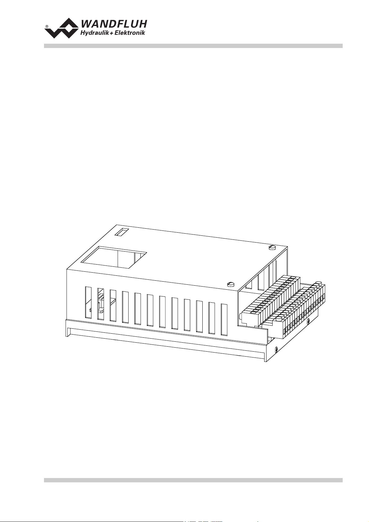
The Amplifier is built in the Eurocard format, put in a housing for mounting on dome-rails, with a screwon/plug-in connector strip.
2.2 Field of application
As an Eurocard, put in a housing for mounting on dome-rails, the field of application of the Amplifier is
situated above all in the industrial field.
2.3 Conformity
The Amplifier has been developed and tested in accordance with the latest technical standards. Applied in
particular was the EU Guideline 89/336/EEC (EMC Guideline).
2.4 Labelling of the product
The housing of the Amplifier is provided with the following adhesive labels:
• with an adhesive type label
• with an adhesive serial number label (with the initials of the tester)
With the PC-Parameterizationsoftware PASO, the following information can be directly read-off the Amplifier:
• Card type
• Software version
Wandfluh AG Tel. ++41 33 672 72 72 E-mail: sales@wandfluh.com Page 3/35
Postfach 134 Fax ++41 33 672 72 12 Internet: www.wandfluh.com Edition 03 38
CH-3714 Frutigen sd1x0bae.doc
Page 4
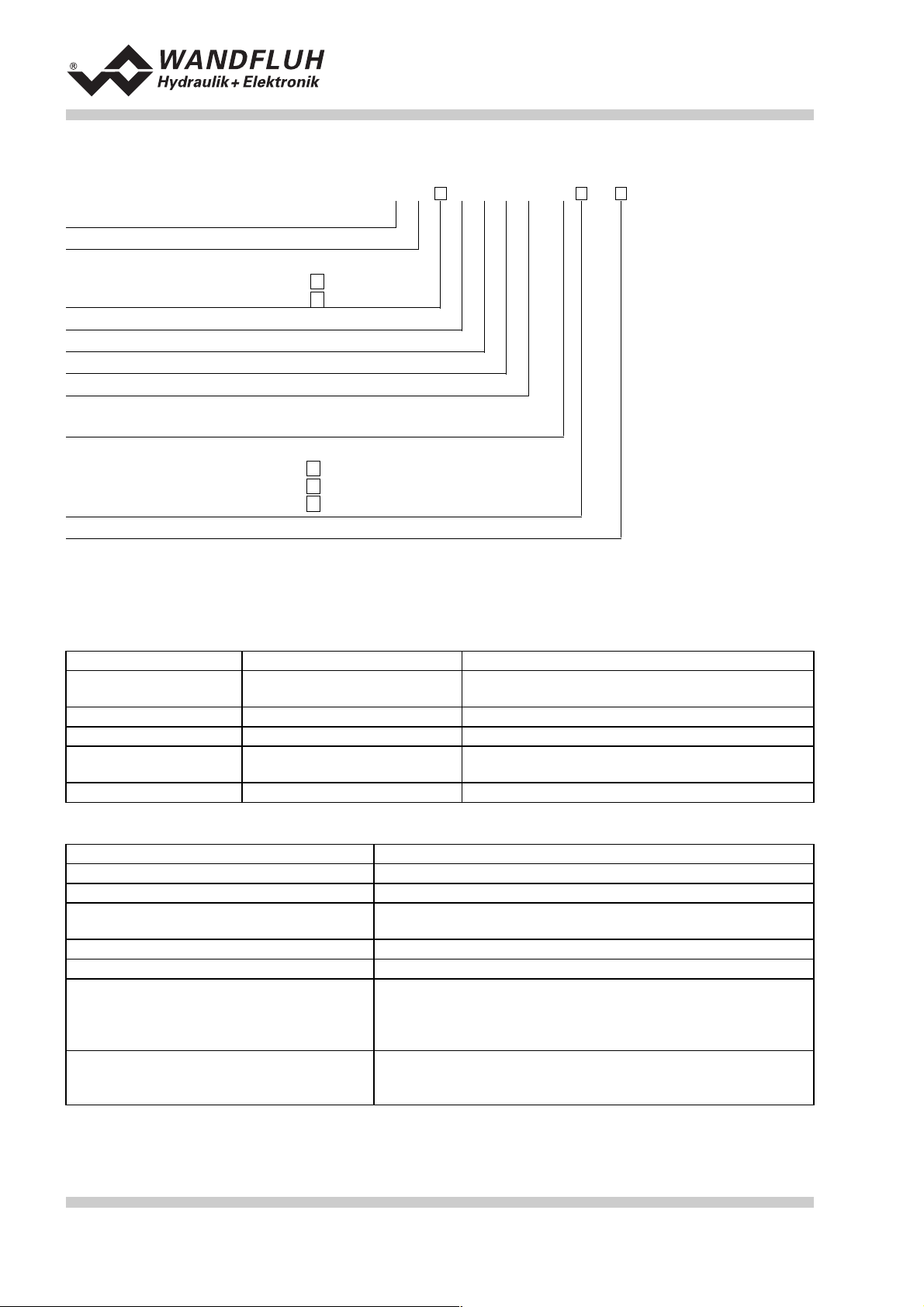
2.5 Type code
Operating guide to Amplifier SD1X0
Snap.On module
Digital
Parameters to be set with:
Multi-function term. MTG02/TESO
PC-Software
Amplifier basic card
2-solenoid version
24VDC supply voltage
Preset value input selection
Hardware configuration
10-Bit resolution
Hardware configuration
without Bus
wiht profibus DP
with CAN-bus
Design-Index (Subject to change)
2.6 Technical data
2.6.1 General specifications
Execution
Dimensions
Installations
Weight
Connections
Ambient temperature
snap-on module housing made of alu
with housing
print plate
with snap-on socket for 35mm dome-rail to DIN 46277
with housing 450g
screw-on/plug-in connector
strip
1
3
A
(on request)
B
(on request)
C
S D1 0 2 D2 0- #
172.0 x 111.0 x 60.5 mm
160.0 x 100.0 mm
CAMDEN rising clamp, plug-in,
max. cable size 4mm²
-20 ... +60° C
A
2.6.2 Electrical specifications
Supply voltage
Voltage range
Ripple on supply voltage
Fuse
Temperature drift
No load power
Analog inputs
Input resistance
Wandfluh AG Tel. ++41 33 672 72 72 E-mail: sales@wandfluh.com Page 4/35
Postfach 134 Fax ++41 33 672 72 12 Internet: www.wandfluh.com Edition 03 38
CH-3714 Frutigen sd1x0bae.doc
Customer must integrate a slow fuse into his electrical system
(A-value = no load power plus max solenoid current)
< 1% with ∆T = 40°C
1 differential input 10-Bit 0 ... 10 VDC
1 differential input 10-Bit 0/4 ... 20 mA
1 input 10-Bit 0 ... +/- 10 VDC
1 input 10-Bit 0/4 ... 20 mA
Voltage input against ground > 100kOhm
Voltage differential input > 27kOhm
Burden for current input = 250Ohm
24 VDC
21 ... 30 VDC
+/-10 %
1.2 W
Page 5

Operating guide to Amplifier SD1X0
Digital inputs
Serial interface
Stabilized output voltage
Solenoid outputs
Solenoid current
Dither
Digital outputs
Free pins
Status indication by LED
LED green
LED yellow
LED red
EMC
Immunity
Emission
2 inputs acitve-low
6 input acitve-high
Switching threshold high 12 - 34VDC
Switching threshold low 0 - 4VDC
1 interface D-SUB 9-pin socket (female) on the front plate
according to RS232 C standard
1 output + 15 VDC, max. Load 100 mA
1 output + 10 VDC, max. Load 10 mA
The solenoid outputs are short circuit proof and protected
against negative voltage peaks by a suppression diode.
Minimum current Imin adjustable 0 ... 950 mA
Default setting 150 mA
Maximum current Imax adjustable Imin ... 1800 mA
Default setting 700 mA
Frequency adjustable 20 ... 250 Hz
Default setting 100 Hz
Level adjustable 0 ... 200 mA
Default setting 100 mA
2 outputs optically coupled.
Open collector connected to Digital ground
Umax 50 VDC
Imax 15 mA
4 pins AUX1 - AUX4 reserved for customer specific
adaptations on the plug-in modules area
Supply voltage
Function
Error
EN 50082-2
EN 55022 Class B
2.6.3 Environment
Storage
In operation
packing: The card must be stored in the original packing
Temperature range: -25 ... +85° C
Resistance to alkali and acid: The card must be protected against alkalis and
acids
Temperature range -20 ... +60° C
Resistance to alkali and acid: The card must be protected against alkalis and
acids
Wandfluh AG Tel. ++41 33 672 72 72 E-mail: sales@wandfluh.com Page 5/35
Postfach 134 Fax ++41 33 672 72 12 Internet: www.wandfluh.com Edition 03 38
CH-3714 Frutigen sd1x0bae.doc
Page 6
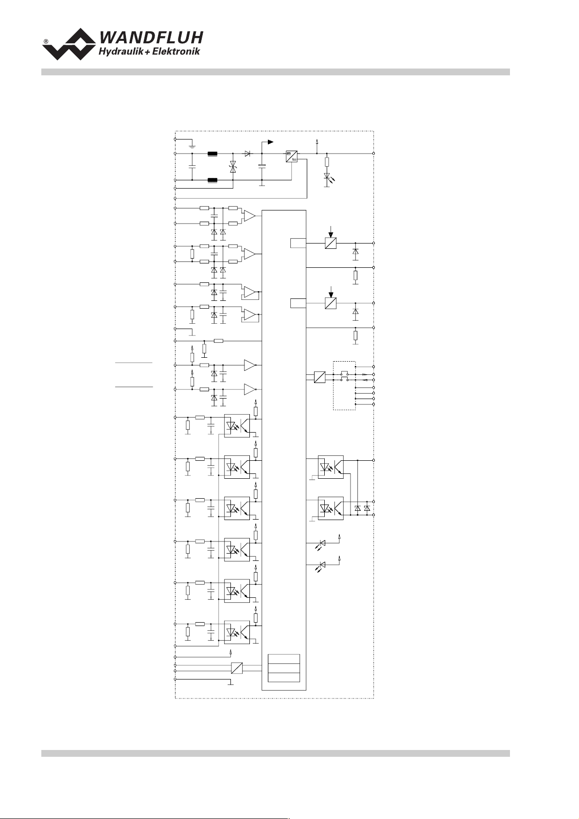
2.7 Block diagram SD1 basic card
Operating guide to Amplifier SD1X0
Earth
Supply voltage 24VDC
Internale GND
Stabilizied output
voltage +10VDC
Analog ue input 1
Voltage signal
Analog ue input 2
Curren t signal
Analog ue input 3
Voltage signal
Analog ue input 4
Curren t signal
Analog ue ground
Analog ue ground wi th
cablebr eak dete ction
Digital input 1
Disable solenoid A
Digital input 2
Disable solenoid B
Digital input 3
Enable control
1
Stabilizied output
5
3
15
19
27
25
31
29
33
35
23
21
2
4
6
+
A/D
-
A/D
A/D
A/D
A/D
controller
PWM
PWM
Micro-
+
-
+
-
+
-
LED g reen
U
I
I-mess
U
I
I-mess
Provision for
plug-in modules
17
9
7
13
11
36
34
32
24
26
28
30
voltage +15VDC
Solenoid A
Solenoid B
AUX5
AUX6/RS23C
AUX7/RS23C
AUX 1
AUX 2
AUX 3
AUX 4
Digital input 4
Solenoid B active
Digital input 5
Ramp Off
Digital input 6
Fixed preset value 1
Digital input 7
Fixed preset value 2
Digital input 8
Fixed preset value 4
Digita l ground
RS 232C
J2-9
J2-2
J2-3
J2-5
8
10
12
14
16
18
+5VDC
EPROM
RAM
EEPROM
20
22
Solenoid B active
18
Solenoid B active
Digi tal ou tput 1
Error
Digi tal ou tput 2
Digital ground
LED red
Error
LED yellow
Wandfluh AG Tel. ++41 33 672 72 72 E-mail: sales@wandfluh.com Page 6/35
Postfach 134 Fax ++41 33 672 72 12 Internet: www.wandfluh.com Edition 03 38
CH-3714 Frutigen sd1x0bae.doc
Page 7
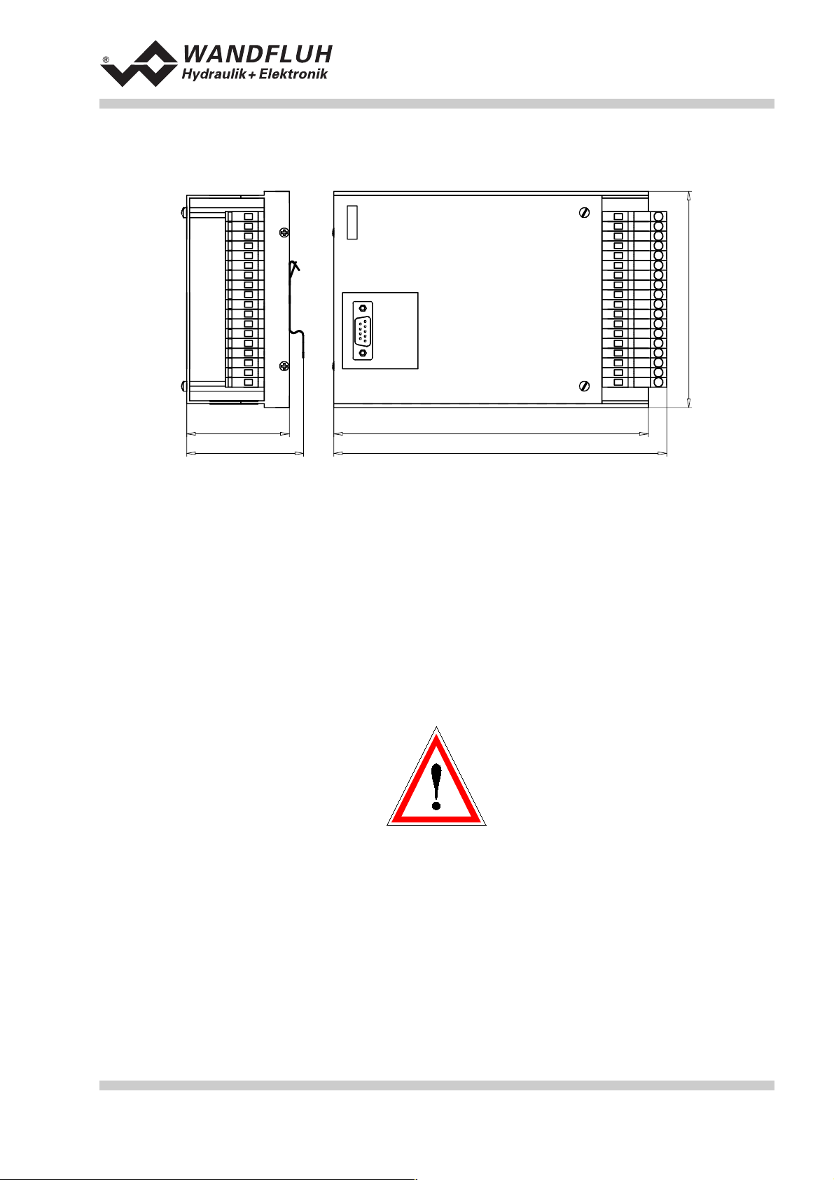
2.8 Dimensions
Operating guide to Amplifier SD1X0
12
34
56
78
910
11 12
13 14
15 16
17 18
19 20
21 22
23 24
25 26
27 28
29 30
31 32
33 34
35 36
111
53
60,5
162,5
172
3 Safety rules
3.1 Installation / Commissioning / Parameterization
• These operating instructions has to be carefully studied beforehand and the instructions are to be
complied with.
• Prior to the installation, all power supply voltages and any other energy sources have to be disconnected.
• During unpacking and when installing it, the card must only be gripped on the housing. Any contact with
soldering points, components and contact pins of the card should be avoided.
• W rong manipulations by the personal cannot be prevented by the card.
• Before the switching on of the supply voltage, the fuse protection, the correct wiring and the conformity of
the power supply voltage with the permissible supply voltage range have to be verified.
• The control monitors the working conditions within the electronic and within the
installation. Uncontrolled movements caused by unforeseen errors cannot be
prevented.
• Danger for persons has to be avoided by installing an emergency stop device
which cuts off the power to the system.
Wandfluh AG Tel. ++41 33 672 72 72 E-mail: sales@wandfluh.com Page 7/35
Postfach 134 Fax ++41 33 672 72 12 Internet: www.wandfluh.com Edition 03 38
CH-3714 Frutigen sd1x0bae.doc
Page 8

Operating guide to Amplifier SD1X0
4 Construction and Function
Refer to the section "Block diagram SD1 " page 6
4.1 Introduction
• The Amplifier is constructed as an Eurocard
• The Eurocard is built into a housing made of alu
• All inputs and outputs have to be contacted trough the screw-on/plug-in connector strip
• The Version SD1102D20-AA has a RS232 (serial) interface, via which the parameterization and the
diagnostics can be made by using the multi-function terminal (MTG02) or PC-Terminalsoftware TESO
• The Version SD1302D20-AA has a RS232 (serial) interface, via which the parameterization and the
diagnostics can be made by using the PC-Parameterization software PASO
4.2 Description of the Function
The Amplifier serves for controlling proportional valves with one or two solenoids and includes constant
current control. Dither frequency and level are adjustable independently. Solenoid outputs are made short
circuit proof. Preset values can be connected in the range of 0 ... 10V or 0 ... ±10V. The analog inputs can be
used also as current inputs 0 ... 20mA or 4 ... 20mA. By that, the Amplifier can be adapted to all common
input signal types. By selecting one of the 4 operating modes, the Amplifier can be set in very universal.
Further, two independently working control loops are selectable.
Amended parameters can be stored in a non volatile memory to have them available when the control system
is switched on again.
4.3 Analog inputs
• The applied analog signal is digitalized in the 10-Bit A/D converter
Attention: By the input range 0 ... 8V, 0 ... 5v or 4 ... 20mA, the resolution is < 10-Bit!
• Differential inputs
Differential inputs must be used if the ground potential of the external preset value generator does not
agree with the analog ground on the Amplifier card.
If the differential input is intended to use like an analog input against analog ground, the - (minus)
connection of the differential input must be connected to the analog ground.
• Analog input with cable break detection
The preset value must be a current signal 4 ... +20mA or a voltage signal from a potentiometer. If a
potentiometer is used, its ground connection must be wired to the terminal "Analog ground with cable
break detection".
• Analog input 1 (for differential voltage signal)
Input voltage range: 0 ... +10V / 0 ... +8V / 0 ... +5V
• Analog input 2 (for differential current signal)
Input current range: 0 ... +20mA / 4 ... +20mA
• Analog input 3 (for voltage signal against analog ground)
Input voltage range: 0 ... ±10V / 0 ... ±8V / 0 ... ±5V
• Analog input 4 (for current signal against analog ground)
Input current range: 0 ... +20mA / 4 ... +20mA
Wandfluh AG Tel. ++41 33 672 72 72 E-mail: sales@wandfluh.com Page 8/35
Postfach 134 Fax ++41 33 672 72 12 Internet: www.wandfluh.com Edition 03 38
CH-3714 Frutigen sd1x0bae.doc
Page 9
Operating guide to Amplifier SD1X0
4.4 Digital inputs
• Digital inputs 1 and 2 are active-low (refer to section "Electrical specifications" page 4) and not galvanically
separated.
• Digital inputs 3 to 8 are acitve-high (refer to section (refer to section "Electrical specifications" page 4) and
galvanically separated via optical couplers.
Attention: Connect common optical coupler ground (14z)!
• Digital input 1 (Disable solenoid A)
If this input is set, solenoid output A is disabled.
• Digital input 2 (Disable solenoid B)
If this input is set, solenoid output B is disabled.
• Digital input 3 (Enable control)
If this input is set, the Amplifier is enabled. Without this enable, no movements can be made.
• Digital input 4 (Solenoid B active)
If this input is set, the solenoid B is acitve (only in the mode of operation 1).
• Digital input 5 (Ramp Off)
The ramp can be temporarily switched off by setting this input. If the ramp is never required, this input
needs not to be set since the ramp time is set to 0s.
• Digital input 6 - 8 (Fixed preset values)
7 fixed preset values, selectable in binary form, are available. When a fixed preset value is selected via
the digital inputs 6 - 8, the external preset value is ineffective.
The following inputs must be set to activate the corresponding fixed preset value:
Fixed preset value Digital input 6 Digital input 7 Digital input 8
External preset value
1
2
1
1
311
4
1
51 1
611
7111
Fixed preset values 1, 2 and 4 can be selected directly, i.e. without coding.
4.5 Outputs
• Proportional solenoid outputs A and B
The 2 solenoid outputs have a current output pulse-width-modulated at 1000Hz with superimposed dither.
The polarity of the connected solenoids is irrelevant. The outputs are short circuit proof and may be
loaded up to 1.8A.
• Digital output 1 (Error)
This output becomes active, when an error is present.
• Digital output 2 (Solenoid B active)
This output becomes acitve, when the solenoid B is active.
• Light emitting diodes LED green / yellow / red
LED green: Supply voltage is present
LED yellow: Solenoid B is acitve
LED red: Indicates an error
Wandfluh AG Tel. ++41 33 672 72 72 E-mail: sales@wandfluh.com Page 9/35
Postfach 134 Fax ++41 33 672 72 12 Internet: www.wandfluh.com Edition 03 38
CH-3714 Frutigen sd1x0bae.doc
Page 10

Operating guide to Amplifier SD1X0
4.6 Mode of operation
The following 4 mode of operation are possible:
• Mode of operation 1
With one analog input (voltage or current) and the digital input 4 (Solenoid B acitve), solenoid A and
solenoid B from a directional valve will be controlled.
0% ... 100% preset value, digital input 4 not active = Imin ... Imax solenoid A
0% ... 100% preset value, digital input 4 active = Imin ... Imax solenoid B
• Mode of operation 2
With one analog input (voltage or current), solenoid A and solenoid B from a directional valve will be
controlled.
0% ... 50% preset value = Imax ... Imin solenoid B
50% ... 100% preset value = Imin ... Imax solenoid A
• Mode of operation 3
With one voltage preset value from 0 ... ±100% at analog input 3, solenoid A and solenoid B from a
directional valve will be controlled.
-100% ... 0% preset value = Imax ... Imin solenoid B
0% ... +100% preset value = Imin ... Imax solenoid A
• Mode of operation 4
In this mode of operation, two solenoids can be controlled independently from each other. Each solenoid
is controlled by separate voltage or current input.
0% ... 100% analog input A = Imin ... Imax solenoid A
0% ... 100% analog input B = Imin ... Imax solenoid B
Wandfluh AG Tel. ++41 33 672 72 72 E-mail: sales@wandfluh.com Page 10/35
Postfach 134 Fax ++41 33 672 72 12 Internet: www.wandfluh.com Edition 03 38
CH-3714 Frutigen sd1x0bae.doc
Page 11
Operating guide to Amplifier SD1X0
5 Operating and Indicating elements
5.1 Introduction
The Amplifier is available as standard in two versions:
• The Version SD1102D20-AA has a RS232 (serial) interface, via which the parameterization and the
diagnostics can be made by using the multi-function terminal (MTG02) or PC-Terminalsoftware TESO
• The Version SD1302D20-AA has a RS232 (serial) interface, via which the parameterization and the
diagnostics can be made by using the PC-Parameterization software PASO
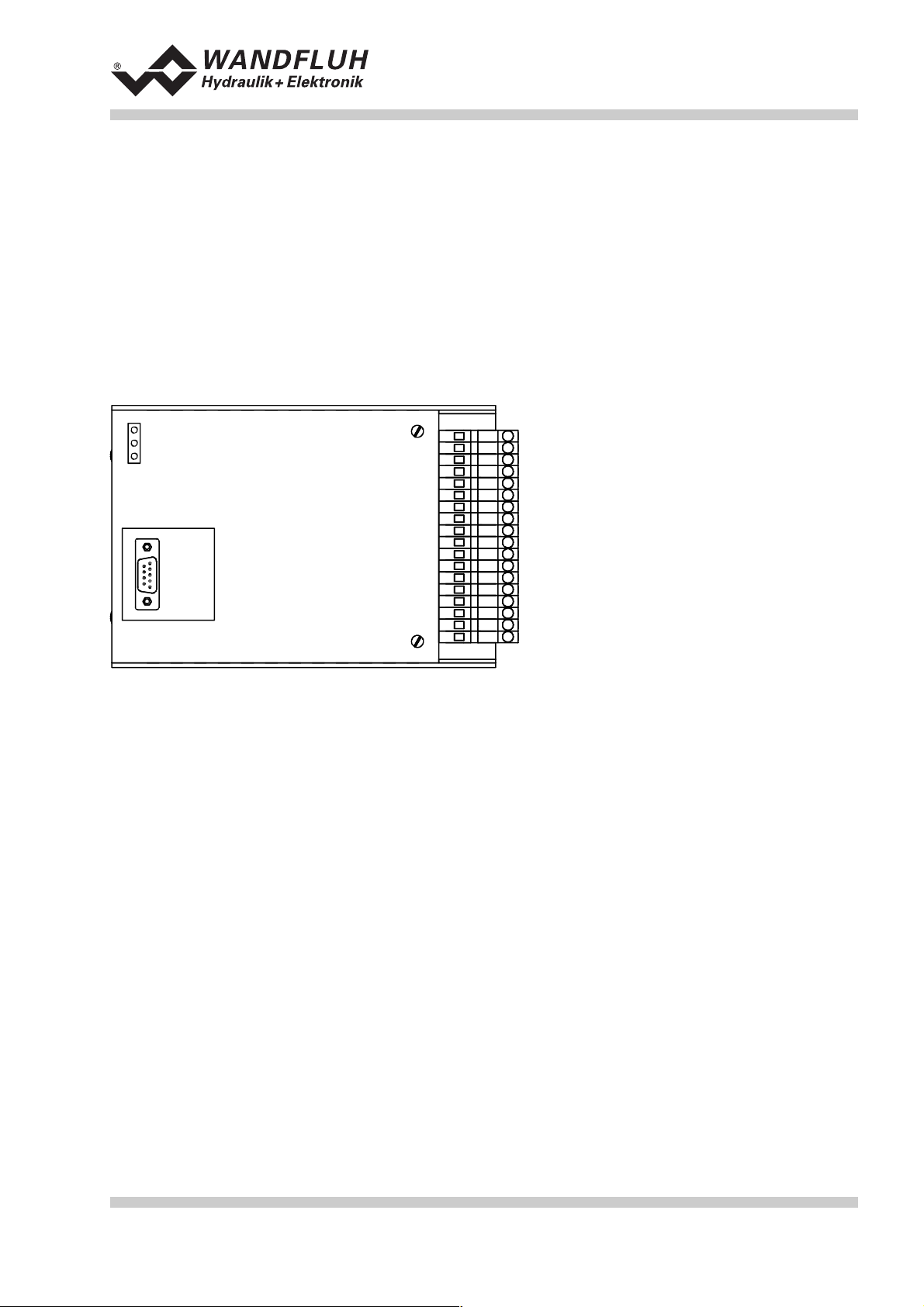
5.2 Top view
LED
grün
gelb
rot
9-pol
D-Sub
Schraub/
Steckleiste
12
34
56
78
910
11 12
13 14
15 16
17 18
19 20
21 22
23 24
25 26
27 28
29 30
31 32
33 34
35 36
Wandfluh AG Tel. ++41 33 672 72 72 E-mail: sales@wandfluh.com Page 11/35
Postfach 134 Fax ++41 33 672 72 12 Internet: www.wandfluh.com Edition 03 38
CH-3714 Frutigen sd1x0bae.doc
Page 12

Operating guide to Amplifier SD1X0
6 Commissioning
Please refer to the section "Safety rules" on page 7.
6.1 Installation / Connection
The Amplifier should preferably be installed in a switchboard cabinet.
For an installation / connection appropriate for EMC, the following points absolutely have to be observed:
• The housing has to be grounded on an electrically conducting sub-surface using a conductor strand with a
large cross section.
• The shielding connection (1) on the screw-on/plug-in connector strip has to be connected with the
switchboard cabinet with an as short as possible conductor with a strand cross section >= 1,5 mm
• The screening of the cable on the housing side must only be connected with the switchboard cabinet
using a large surface area and low Ohm connection (best by means of a clamp shackle).
• Solenoid- and signal cables must not be laid parallel to high voltage cables.
6.2 Connection instructions
The contact assignment of the following description refers to the section "Connection examples" page 15.
2.
6.2.1 Supply voltage
• For the dimensioning of the 24VDC power supply, the maximum power demand of the solenoid has to be
calculated (in case of directional valves, only the maximum power demand of one solenoid has to be
considered). This power then has to be increased by the no load power from the Amplifier (refer to the
section "Electrical specifications" page 4).
• The limit values of the supply voltage and its residual ripple indispensably have to be complied with (refer
to the section "Electrical specifications" page 4).
• The Amplifier has to be protected with a slow acting fuse. The rating of this fuse should correspond to
approx. 1.5 times the current calculated above.
6.2.2 Solenoid outputs
For the solenoid outputs, the polarity, with which the solenoids are connected, does not matter. The following,
however, has to be observed:
• The conductor strand cross section has to be adapted to the solenoid current
• Screened cables have to be used; the screen must be grounded only on the switchboard cabinet side.
Wandfluh AG Tel. ++41 33 672 72 72 E-mail: sales@wandfluh.com Page 12/35
Postfach 134 Fax ++41 33 672 72 12 Internet: www.wandfluh.com Edition 03 38
CH-3714 Frutigen sd1x0bae.doc
Page 13

6.2.3 Digital inputs and outputs
• Digital inputs 1 and 2 are active-low and not galvanically separated.
• For activation, they have to be connected to 0V (ground)
Operating guide to Amplifier SD1X0
control extern control intern
0V
24V
• Digital inputs 3 - 8 are acitve-high and galvanically separated via optical couplers.
• In order to use the galvanically separation, the connection "Digital ground" (18) has to be connected to the
ground of the external digital signal transmitter.
• If no galvanically separation is necessary, the "Digital ground" (18) can be connected with the minus of the
24VDC power supply.
• For activation, they have to be connected to +24VDC.
control extern control intern
+24V
galvanically
separation
0V
18
• The digital outputs are "open collector" outputs.
control intern
galvanically
separation
control extern
+24V
18
Wandfluh AG Tel. ++41 33 672 72 72 E-mail: sales@wandfluh.com Page 13/35
Postfach 134 Fax ++41 33 672 72 12 Internet: www.wandfluh.com Edition 03 38
CH-3714 Frutigen sd1x0bae.doc
Page 14

6.2.4 Analog inputs 10-Bit
• There are two voltage and two current inputs available.
• One of each is a differential input.
• Each input can be adjust for each solenoid output.
control extern control intern
Operating guide to Amplifier SD1X0
voltage
input
large surface
connection
current
input
large surface
connection
+
-
+
-
6.2.5 Configuration of the analog inputs 10-Bit
The analog inputs 10-Bit can be configured as follows:
Input signal Connector strip assignment Input range
Voltage input against analog ground + to 33 / ground to 23 0 ... +5/8/10V
0 ... ±5/8/10V
Voltage input against analog ground with cable
+ to 33 / ground to 21 0 ... +5/8/10V
break detection
Voltage differential input + to 27 / - to 25 0 ... +5/8/10V
Current input against analog ground + to 35 / ground to 23 0 ... +20mA
4 ... +20mA
Current differential input + to 31 / - to 29 0 ... +20mA
4 ... +20mA
Wandfluh AG Tel. ++41 33 672 72 72 E-mail: sales@wandfluh.com Page 14/35
Postfach 134 Fax ++41 33 672 72 12 Internet: www.wandfluh.com Edition 03 38
CH-3714 Frutigen sd1x0bae.doc
Page 15

6.3 Connection examples
6.3.1 Mode of operation 1
• +10VDC voltage preset value with potentiometer
• digital inputs with switches without galvanically separation
Operating guide to Amplifier SD1X0
Supply
voltage 24VDC
Earth
Preset value from
potentiomete r
Common optical
coupler ground
Solenoid B aktive
Enable control
Ramp off
Fixed preset value 1
Fixed preset value 2
Fixed preset value 4
Disable solenoid A
Disable solenoid B
Fuse
+
-
Rack
5
SD1
3
1
19
33
23
18
8
6
10
12
14
16
2
4
6.3.2 Mode of operation 4
• +10VDC voltage preset value with potentiometer
• digital inputs with switches without galvanically separation
Directional valve
9
7
13
11
20
22
Rack
Rack
24V 24V
Error
active
Solenoid B
active
Wandfluh AG Tel. ++41 33 672 72 72 E-mail: sales@wandfluh.com Page 15/35
Postfach 134 Fax ++41 33 672 72 12 Internet: www.wandfluh.com Edition 03 38
CH-3714 Frutigen sd1x0bae.doc
Page 16

Operating guide to Amplifier SD1X0
Supply
voltage 24VDC
Earth
Preset value A
from potentiometer
Preset value B
from potentiometer
Common optical
coupler gro und
Enable control
Ramp off
Fixed preset value 1
Fixed preset value 2
Fixed preset value 4
Disable solenoid A
Disable solenoid B
Fuse
+
-
Rack
5
SD1
3
1
19
27
25
23
33
23
18
6
10
12
14
16
2
4
9
7
13
11
20
22
Rack
Rack
24V 24V
Error
active
Solenoid B
active
Wandfluh AG Tel. ++41 33 672 72 72 E-mail: sales@wandfluh.com Page 16/35
Postfach 134 Fax ++41 33 672 72 12 Internet: www.wandfluh.com Edition 03 38
CH-3714 Frutigen sd1x0bae.doc
Page 17

Operating guide to Amplifier SD1X0
7 Settings
Please refer to the section "Safety rules" on page 7.
7.1 Introduction
• The system- and parameter settings can be made it depends on the card version either via the RS232
interface with the multi-function terminal MTG02 resp. the PC-Terminal software TESO or the PCParameterization software PASO.
• For information about the operation via the multi-function terminal MTG02 resp. PC-Terminalsoftware
TESO please refer to section "Cyclic menu construction" page 28.
• For information about the operation via the PC-Parameterization software PASO please refer to section
"PASO Installation and Operation" page 29.
• The following instructions refer to the Menu order of the PC-Parameterization software PASO. To look for
the corresponding points in the version with multi-function terminal MTG02 resp. PC-Terminal software
TESO, the corresponding cyclic menu construction is also displayed.
• Depending on the software version and connecting card type, certain settings may be blocked.
7.2 General
In order for some of the menus resp. sub-menus listed below to be able to be selected, first a parameter set
must be present int the memory or else a new one has to be established. To do this, one of the following
commands has to be executed:
• File_New
• File_Open
• Start PASO with the connection to the Amplifier (in this case, the data are loaded from the Amplifier)
7.3 Tips for the first commissioning
• Connect the power supply, leave the Amplifier still switched off
• Switch off the hydraulic drive (hydraulics switched off)
• Carefully check the connections
• Switch on the power supply
• Establish the communication with PASO (connect the PC and the Amplifier with an RS232 cable and start
PASO)
• In the menu "Configuration", define the correct input for the preset value
• In the menu "Parameters_Valves", set the desired current for the solenoids
7.4 File - Menu (only PASO - Version)
Contained in the File menu are the menu points, which concern the file handling and the printing of the
parameters. In the "On Line Mode", some of these menu points are blocked..
7.4.1 File_New
This menu point is active only in the "Off Line Mode".
With this command, a new file can be opened. A selection window will be displayed. In this window, the
desired function from the PASO can be selected. The selected function should correspond to the function of
the connected digital card. All parameter values are set to standard values. The required values can now be
entered.
7.4.2 File_Open...
This menu point is only active in the "Off Line Mode".
With this command, an existing file from a storage medium is opened. First the file selection window appears.
In this window the required file can now be selected and opened with ”OK”. If the function of the selected file
does not correspond to the current function of the PASO, a message will be displayed. A selection is now
possible, if the event should be cancelled or if the current function from the PASO should change over to the
Wandfluh AG Tel. ++41 33 672 72 72 E-mail: sales@wandfluh.com Page 17/35
Postfach 134 Fax ++41 33 672 72 12 Internet: www.wandfluh.com Edition 03 38
CH-3714 Frutigen sd1x0bae.doc
Page 18

Operating guide to Amplifier SD1X0
new function of the selected file. The parameter values can now be edited and changed as required under
the menu points “Configuration” or “Parameters”.
7.4.3 File_Save
With this command, the parameters are saved on a data storage medium. All parameter values of all input
windows are saved under the current file name. If no file name has been defined yet, then first the file
selection window appears (refer to File_Save as...).
7.4.4 File_Save as...
With this command, the parameters are saved on a data storage medium. All parameter values of all input
windows are saved under the file name entered.
First the file selection window appears (see File_Open). In this window the desired file name can now be
entered. If the file name is entered without an extension, then the extension “.par” is automatically assigned
to it. After actuating the key “Save”, the file information window appears (see File_File-Info). In this window
the required entries can now be made. With the key “Save”, the file is then finally saved under the selected
file name. With the key “Cancel”, one changes back to the file window.
7.4.5 File_Print...
With this command, the current parameters are printed in ASCII text format. The File_Print window is
opened. In this window one can now select, whether the printing process is to be to a printer or to a file.
If the output is to be to a printer, then the Windows printer selection window is opened.. In this window,
please do not select “Print to File”. If you do, a new program start might possibly be required and you
could lose any data not yet saved.
If the output is to be to a file, then the file selection window appears. In this window the desired file name can
now be entered. If the file name is entered without an extension, then automatically the extension “.txt” is
assigned to it.
7.4.6 File-Info
With this command, the file information of an existing file is displayed. The file information consists of the
following parts:
Date, time Date, time of saving.
File name: The file name, under which the file has been saved.
Card type: The type of digital control card at the moment of saving. If no card is connected, then this
indication remains empty. In case of saving during “On Line Operation”, this indication is
updated.
Operator: The name of the originating person.
Remarks: Possibility to enter remarks concerning the file.
When the File_Info window appears during the execution of the command “File_Save”, then the
corresponding entries can be made in the various fields (with the exception of “Date”, “Time”, “File name” and
“Card type”, which cannot be edited). When the File_Info window appears during the execution of the
command “File_File-Info”, then the various fields cannot be edited.
7.4.7 File_Off Line (On Line)
Off Line
With this command, the connection with the Amplifier is interrupted. All menu points, which call for a
communication with the Amplifier, are blocked. The PASO software now runs in the “Off Line Mode”. The
loading, saving and the editing of parameter files is possible in this mode.
Wandfluh AG Tel. ++41 33 672 72 72 E-mail: sales@wandfluh.com Page 18/35
Postfach 134 Fax ++41 33 672 72 12 Internet: www.wandfluh.com Edition 03 38
CH-3714 Frutigen sd1x0bae.doc
Page 19

Operating guide to Amplifier SD1X0
On Line
With this command, the connection with the Amplifier is established. The communication with the Amplifier is
briefly tested. If the connection works, then the user has the option of taking over the parameters from the
Amplifier or of transferring the parameters to the Amplifier. During the transfer of the parameters, the user
has the possibility of aborting the operation.
Before parameters are transfered to the Amplifier, a verification is carried out as to whether the version of the
Amplifier supports the parameter values. If this is not the case, then a message is issued and a transfer to
the controller is not possible.
If the parameters have been taken over by the Amplifier, then they are briefly checked. If one or several of
the parameters are outside the tolerance, standard values are assigned instead and a message is issued. If
the transfer was successful and the verification check was also successful, then the software subsequently
runs in the On Line Mode”. The loading of parameter files is not possible in this mode.
7.4.8 File_Exit
With this command, the parameterization program PASO is terminated. If parameter data have been
changed and have not yet been saved, then the question appears, as to whether these data should be saved.
When terminating, the current data from the configuration window are also saved.
7.5 Fixed preset value - Menu
SD1x02D2 Ver. E
<MODE>
Language:english
+-<±> ok<E>
....: <M>
Select: <E>
System: <M>
Select: <E>
Parameters <M>
Select: <E>
fixed preset:<M>
Select: <E>
When one of the fixed preset values 1 - 7 is selected, the external preset value is ineffective.
7.5.1 Generator
In this window, all adjustments according to the fixed preset values will be made.
Field Parameter description Range / Step
Fixed preset value X Desired value of the corresponding fixed preset value. The
adjusted %-value refer to the adjusted solenoid current
range (0% = Imin, 100% = Imax). A positive %-value will
activate the solenoid A, a negative %-value will activate the
solenoid B.
Parameters: <M>
Select: <E>
....: <M>
Select: <E>
Service: <M>
Select: <E>
0 ... 100%
0.1%
Wandfluh AG Tel. ++41 33 672 72 72 E-mail: sales@wandfluh.com Page 19/35
Postfach 134 Fax ++41 33 672 72 12 Internet: www.wandfluh.com Edition 03 38
CH-3714 Frutigen sd1x0bae.doc
Page 20

7.6 Parameters - Menu
Operating guide to Amplifier SD1X0
SD1x02D2 Ver. E
<MODE>
Language:english
+-<±> ok<E>
System: <M>
Select: <E>
Parameters: <M>
Select: <E>
Service: <M>
Select: <E>
In this window, all parameter values of the Amplifier will be made.
7.6.1 Parameters_Valves
Parameters: <M>
Select: <E>
....: <M>
Select: <E>
current A/B: <M>
Select: <E>
....: <M>
Select: <E>
dither: <M>
Select: <E>
In this window, all settings specific to the valves will be made.
Field Parameter description Range / Step
Preset value internal
(only PASO-Version)
If this switch is selected, an internal preset value from 0%
resp. 100% will be active during the setting of the Imin resp.
Imax. If this switch is not selected, the external preset value
will be active.
Prop. Valve settings The minimum and the maximum solenoid current can be
set separately for each solenoid output, corresponding to
0% resp. 100% preset value.
In the "Off Line Mode", the displayed current value is the
theoretical preset current. This makes it possible to set the
Imin/Imax values without a solenoid or a valve is connected
to the Amplifier (only PASO-Version).
In the "On Line Mode", if the Imin setting is active, a preset
value of 0% resp. if the Imax setting is active, a preset
value of 100% is automatically applied internally (with the
PASO-Version only if the switch "Preset value internal" is
selected).
As a result of the digitalisation, the numbers entered max
be modified to less "rounded-off" number.
Imin A Set minimum solenoid current A.
(= solenoid current by 0% preset value)
Imax A Set maximum solenoid current A.
(= solenoid current by 1000% preset value)
Imin B Set minimum solenoid current B.
(= solenoid current by 0% preset value)
Imax B Set maximum solenoid current B.
(= solenoid current by 1000% preset value)
0 ... 950mA
2mA
0 ... 1800mA
2mA
0 ... 950mA
2mA
0 ... 1800mA
2mA
Frequency The dither frequency can be set in steps. 20, 40, 60, 70, 80, 90,
100, 110, 125, 140,
165, 200, 250Hz
Level Level of the superimposed AC signal 0 ... 199mA
2mA
Wandfluh AG Tel. ++41 33 672 72 72 E-mail: sales@wandfluh.com Page 20/35
Postfach 134 Fax ++41 33 672 72 12 Internet: www.wandfluh.com Edition 03 38
CH-3714 Frutigen sd1x0bae.doc
Page 21

7.6.2 Parameters_Analog inputs
Parameters: <M>
Select: <E>
Operating guide to Amplifier SD1X0
analogInput: <M>
Select: <E>
....: <M>
Select: <E>
...: <M>
Select: <E>
Dependent of the settings from the menu "Configuration_System", certain settings may be blocked.
Field Parameter description Range / Step
Analog inputs Dependent of the selected mode of operation and the
selected analog inputs, the settings of the parameter
"Offset" and "Window" can be made here (refer to the
below figure)
Offset This parameter can be set only in the mode of operation 2.
Dependent of the selected signal type, the setting is in V or
mA.
Voltage:
Current:
0 ... ±1.24V
0 ... ±2.48mA
Window X Window width for each analog input. Dependent of the
selected mode of operation are one or two settings
possible. Dependent of the selected signal type, the setting
is in V or mA.
Voltage:
0 ... ±4.96mA
Current:
Solenoid current [%]
100
0.01V
0.02mA
0 ... 2.48V
0.02V
0.04mA
Window
0
Preset value [%]0100
Offset
Wandfluh AG Tel. ++41 33 672 72 72 E-mail: sales@wandfluh.com Page 21/35
Postfach 134 Fax ++41 33 672 72 12 Internet: www.wandfluh.com Edition 03 38
CH-3714 Frutigen sd1x0bae.doc
Page 22

7.6.3 Parameter_Ramps
Parameters: <M>
Select: <E>
Operating guide to Amplifier SD1X0
....: <M>
Select: <E>
ramps A/B: <M>
Select: <E>
....: <M>
Select: <E>
In this window, all adjustments according to the ramp function will be made.
Field Parameter description Range / Step
Solenoid A
Solenoid B
After a preset value jump, the new preset value is
approached via a linear ramp (with the set ramp time). A
ramp time up and ramp time down can be set separately
for each solenoid.
Ramp up The set ramp time refer to a preset value jump from 0% to
100%
Ramp down The set ramp time refer to a preset value jump from 100%
to 0%
0 ... 51s
0.05s
0 ... 51s
0.05s
7.6.4 Parameters_Store (not PASO-Version)
Parameters: <M>
Select: <E>
....: <M>
Select: <E>
....: <M>
Select: <E>
store: <M>
Select: <E>
With this command, the set parameters can be stored in the non volatile memory (EEPROM) on the
Amplifier. With the PASO-Version, this will be made automatically by leaving a input window with the key
"OK".
7.7 Configuration - Menu
SD1x02D2 Ver. E
<MODE>
Language:english
+-<±> ok<E>
System: <M>
Select: <E>
In this window, the settings of the function of the Amplifier will be made.
Wandfluh AG Tel. ++41 33 672 72 72 E-mail: sales@wandfluh.com Page 22/35
Postfach 134 Fax ++41 33 672 72 12 Internet: www.wandfluh.com Edition 03 38
CH-3714 Frutigen sd1x0bae.doc
Parameters: <M>
Select: <E>
Service: <M>
Select: <E>
Page 23

Operating guide to Amplifier SD1X0
7.7.1 Configuration_System
In this window, the basic function of the Amplifier will be adjust.
In the version with multi-function terminal resp. PC-Terminalsoftware TESO, a password question appears.
Press the + and - keys in succession as the password.
Field Parameter description Range / Step
Mode of operation Select the desired mode of operation 1 / 2 / 3 / 4
Cablebreak Switch on/off the cablebreak detection of the analog inputs no
yes
Input Signal In the mode of operation 4, the selection is possible, if the
following settings should be for the analog input for the
Input A
Input B
solenoid A or for the solenoid B.
Signal type Select the desired signal type. Dependent of the selected
mode of operation, not all signal types are available.
0-5V
0-8V
0-10V
0-20mA
4-20mA
Used input A selection can be made between voltage and current
inputs. Only the corresponding inputs to the selected signal
type are available.
AnaInp1 [V]
AnaInp2 [mA]
AnaInp3 [V]
AnaInp4 [mA]
Inversion The preset value can be inverted.
0% preset value = 100% solenoid current
no
yes
100% preset value = 0% solenoid current
With leaving the window with the key "OK", a check will be made, if for the input A and input B the used input
is different. If not, a message will be displayed and the window cannot be left.
7.7.2 Configuration_Digital I/O
SD1x02D2 Ver. E
<MODE>
Language:english
+-<±> ok<E>
datas: <M>
Select: <E>
System: <M>
Select: <E>
Service: <M>
Select: <E>
diagnostics: <M>
Select: <E>
Parameters: <M>
Select: <E>
SetDigInputs:<M>
Select: <E>
Service: <M>
Select: <E>
With this command, the digital inputs of the connected Amplifier can be set to active, not active or released.
Field Parameter description Range / Step
Digital Inputs Set digital input with software
Reset digital input with software
Read in the external digital input
1
0
X
Wandfluh AG Tel. ++41 33 672 72 72 E-mail: sales@wandfluh.com Page 23/35
Postfach 134 Fax ++41 33 672 72 12 Internet: www.wandfluh.com Edition 03 38
CH-3714 Frutigen sd1x0bae.doc
Page 24

7.7.3 Configuration_Default setting
ED1x02D2 Ver. E
<MODE>
Operating guide to Amplifier SD1X0
Language:english
+-<±> ok<E>
System: <M>
Select: <E>
Parameters: <M>
Select: <E>
Service: <M>
Select: <E>
With this command, the default settings in the EPROM on the connected Amplifier will be loaded and read to
the PC in the PASO-Version.
7.7.4 Configuration_Interface (only PASO-Version)
With this command, the serial output port for the communication with the connected control card can be
selected. This setting is automatically saved in the file “konfig.kon” and taken over with a new start.
If the software is in the "On Line Mode", then the communication is broken off when the “OK” key is pushed.
If the software is in the "Off Line Mode", then a confirmation window appears with the question, as to whether
the communication with the axis controller is to be tested. If the communication works, a corresponding
message is issued and a connection with the axis controller can be established via the menu point File_On
Line.
If no communication can be established (transmission interference or no axis controller card connected), then
an error message appears. All menu points and keys, which contain an action in connection with the
communication, are then blocked.
Field Parameter description Range / Step
Output port The serial port of the PC can be selected. COM1
COM2
COM3
COM4
7.7.5 Configuration_Language
SD1x02D2 Ver. E
<MODE>
Language:english
+-<±> ok<E>
System: <M>
Select: <E>
Parameters: <M>
Select: <E>
Service: <M>
Select: <E>
In this window, the language can be selected, with which the menu will be inscribed. In the version with multifunction terminal MTG02 resp. PC-Terminalsoftware TESO, the menu language question appears after the
card is switched on for the first time. During the execution, the language can be changed at any time in menu
"System". In the PASO-Version, this setting is automatically saved in the file "konfig.kon" and taken over with
a new start.
Field Parameter description Range / Step
Language Field, from which the desired language can be selected. deutsch
english
français
Wandfluh AG Tel. ++41 33 672 72 72 E-mail: sales@wandfluh.com Page 24/35
Postfach 134 Fax ++41 33 672 72 12 Internet: www.wandfluh.com Edition 03 38
CH-3714 Frutigen sd1x0bae.doc
Page 25

7.8 Analysis - Menu
Operating guide to Amplifier SD1X0
SD1x02D2 Ver. E
<MODE>
Language:english
+-<±> ok<E>
System: <M>
Select: <E>
Parameters: <M>
Select: <E>
Service: <M>
Select: <E>
In the Analysis menu, measured values can be displayed on-line and various process signals can be
recorded and correspondingly displayed.
7.8.1 Analysis_Values
Service: <M>
Select: <E>
datas: <M>
Select: <E>
diagnostics: <M>
Select: <E>
SetDigInputs:<M>
Select: <E>
This menu point is active only in the "On Line Mode".
With this command, all relevant data of the connected axis controller are read-in and displayed. The values
are continually updated (on-line).
Field Description Unit
Supply voltage Power supply voltage of the card V
Analog input X Voltage- resp. current value of the analog input for the
solenoid A
Analog input X Voltage- resp. current value of the analog input for the
solenoid B
V
mA
V
mA
Control voltage A Control signal before solenoid output A V
Solenoid current A Solenoid current of solenoid A mA
Control voltage B Control signal before solenoid output B V
Solenoid current B Solenoid current of solenoid B mA
Digital inputs 1 - 8 Logical conditions of the digital inputs
When the inputs are set
When the inputs are not set
1
0
Digital outputs 1 - 2 Logical conditions of the digital outputs
When the outputs are set
When the outputs are not set
1
0
7.8.2 Analysis_Diagnostic
Service: <M>
Select: <E>
datas: <M>
Select: <E>
diagnostics: <M>
Select: <E>
SetDigInputs:<M>
Select: <E>
With this command, possibly present errors on the connected Amplifier are indicated. The error is read in
once. In the version with multi-function terminal MTG02 resp. PC-Terminalsoftware TESO, only the text in the
column "Diagnostics" will be displayed. For making an exact analysis of the error, this operating guide has to
be contacted. In the PASO-Version, a complete description of the error will be displayed.
Diagnostics: Error Error remedy
Wandfluh AG Tel. ++41 33 672 72 72 E-mail: sales@wandfluh.com Page 25/35
Postfach 134 Fax ++41 33 672 72 12 Internet: www.wandfluh.com Edition 03 38
CH-3714 Frutigen sd1x0bae.doc
Page 26

Operating guide to Amplifier SD1X0
Power supply fault If the supplied voltage < 18VDC. the
Disable and reenable the control
solenoid outputs are blocked.
Cable break supply This error is only detected, if the
Disable and reenable the control
parameter "cablebreak" is set to "yes".
The power supply and/or the ground of
the preset generator is interrupted. The
solenoid outputs are blocked.
Cable break input X This error is only detected, if the
Disable and reenable the control
parameter "cablebreak" is set to "yes".
The preset value signal to the controller
is interrupted. The corresponding
solenoid output is blocked.
Solenoid output X The connection to the solenoid is
Disable and reenable the control
interrupted. The corresponding solenoid
output is blocked. This fault is only
detected if the solenoid current should
be > 100mA.
Memory: XX Error in verifying EEPROM-RAM data.
The solenoid outputs are blocked.
Switch off and on the control or resave
the parameters
7.9 Help - Menu (only PASO-Version)
The PASO-Help based on the standard Windows-Help construction.
7.9.1 Help_Description of the function
A general information about the function of the Amplifier will be displayed.
7.9.2 Help_Contents
The list of contents of the PASO-Help will be displayed.
7.9.3 Help_Index
The list of index of the PASO-Help will be displayed.
7.9.4 Help_Card Identification
This menu point is only active in the "On Line Mode".
Here the current version of the hardware and the software from the connected Amplifier will be read and
displayed.
7.9.5 Help_Info
Information about PASO and its version.
Wandfluh AG Tel. ++41 33 672 72 72 E-mail: sales@wandfluh.com Page 26/35
Postfach 134 Fax ++41 33 672 72 12 Internet: www.wandfluh.com Edition 03 38
CH-3714 Frutigen sd1x0bae.doc
Page 27

Operating guide to Amplifier SD1X0
8 The system does not work
In this section, the generally possible errors and the procedures for eliminating them are listed and explained.
8.1 Procedure
The following check list can be used to help, if a problem is arised.
Question: Action: Possible errors and causes
Green LED off Analysis_Values ● The 24VDC supply is not switched on
● The 24VDC supply is wrongly or not connected
● If the supply voltage value is between 21VDC and 30VDC, the
supply is correct
Red LED on Analysis_Values
Power supply error
Analysis_Diagnostic
Cablebreak supply
Analysis_Diagnostic
Cable break input X
Analysis_Diagnostic
Solenoid output X
Analysis_Diagnostic
Memory XX
● The supplied voltage is under 18VDC. The error is also displayed
if a supplied voltage interruption occurred (t > 250ms).
● Is the supplied power enough?
● Is the AC voltage too high (refer to section "Electrical
specifications" page 4)
● When the error is cleared, disable the controller for a short period
and re-enable (DigInp 3)
● If the preset value encoder is a potentiometer, the supply is
absent
● The ground connection of the potentiometer is not connected to
the connector strip.
● Check connections to the potentiometer
● If the cablebreak detection is not desired, switch off the
cablebreak function in the menu "Configuration".
● When the error is cleared, disable the controller for a short period
and re-enable (DigInp 3)
● The cable break detection functions only with potentiometer or 4
... 20mA preset value.
● The preset value signal is absent or is smaller than 4mA.
● Check the preset value signal connections between the preset
value encoder and card.
● If the cablebreak detection is not desired, switch off the
cablebreak function in the menu "Configuration".
● When the error is cleared, disable the controller for a short period
and re-enable (DigInp 3).
● The connections to the solenoid is interrupted.
● Check the connections to the solenoids.
● When the error is cleared, disable the controller for a short period
and re-enable (DigInp 3) or disable the corresponding solenoid
only a for short period and re-enable.
● Error in verifying EPROM-RAM data.
● Error has occurred while writing to or reading from the EPROM.
● If fault occurred while storing, store again, then switch card off
and on.
● If fault occurred when card was switched on, store parameter,
then switch card off and on.
Wandfluh AG Tel. ++41 33 672 72 72 E-mail: sales@wandfluh.com Page 27/35
Postfach 134 Fax ++41 33 672 72 12 Internet: www.wandfluh.com Edition 03 38
CH-3714 Frutigen sd1x0bae.doc
Page 28

Operating guide to Amplifier SD1X0
9 Cyclic menu construction
The operation via the display/keys or the multi-function terminal MTG02 resp. the PC-Terminalsoftware
TESO is in the form of a cyclic menu structure.
Carte
Identification
Parameters: <M>
Select: <E>
System: <M>
Select: <E>
Service: <M>
Select: <E>
To move through the cyclic menu, press the key "MODE". All existing menu items are listed in the section
"Settings" page 17 with the number 7.x.
To enter a program branch, press the key "ENTER":
Parameters: <M>
Select: <E>
current A/B: <M>
Select: <E>
regulator: <M>
Select: <E>
dither: <M>
Select: <E>
to move through the sub cycle menu, press the key "MODE". All existing menu items are listed in the section
"Settings" page 17 with the number 7.x.x.
To enter a parameter branch, press the key "ENTER":
current A/B: <M>
Select: <E>
Imin A: 150mA
+-<±> ok<E>
more Parameters
+-<+> ok<E>
With the keys "+" and "-", the desired value can be adjusted. With the key "ENTER", the next parameter
value will be displayed. All existing parameters are listed in the section "Settings" page 17 with the column
"Field".
The detailed description of all commands and parameters is located in the section "Settings" page 17 of this
operating guides.
Wandfluh AG Tel. ++41 33 672 72 72 E-mail: sales@wandfluh.com Page 28/35
Postfach 134 Fax ++41 33 672 72 12 Internet: www.wandfluh.com Edition 03 38
CH-3714 Frutigen sd1x0bae.doc
Page 29

Operating guide to Amplifier SD1X0
10 PASO Installation and Operation
The parameterisation software PASO serves for the parameterising and diagnosing of digital control cards of
the WANDFLUH AG company. The software provides a user interface, through which by means of a
keyboard or a mouse all adjustments and settings can easily be carried out. The communication with the
digital control card takes place through a serial RS 232 interface.
The parameterisation software PASO can only be utilised in connection with a digital control card of
the WANDFLUH AG company. It is necessary to carefully study the operating instructions of the
connected digital control card beforehand.
10.1 PASO system requirements
A description of the different PASO versions is located in the file "history.pdf". This file is located in the
directory where the PASO will be installed.
In order to be able to correctly utilise the PASO, an IBM-compatible PC with the following requirements has to
be available:
• Processor 486 or higher, min. 33MHz, min. 8MB RAM
Recommended: 80586 66MHz or higher, 16 MB RAM or more
• Free harddisk storage space of minimum 4MB, plus storage space for program files
• Operating system MS-WINDOWS 95/98, NT 4.0 or higher
• Standard VGA or higher graphics card, recommended resolution 800x600
• At least one serial RS 232 interface (with Laptops resp. Notebooks without a serial interface, this can be
realised with a PCMCIA-card)
• Serial RS232 cable 1:1 (RxD and TxD not crossed)
10.2 PASO installation
The PASO software can be downloaded via the Internet free of charge (www.wandfluh.com/Download =>
PASO ED1/SD1 => Download Program files) or on request delivered on an installation-CD.
The installation of the PASO is then carried out by executing the file "setupPasoEd1vxxxx.exe", where "xxxx"
means the current version (e.g. setupPasoEd1v3000.exe, see also version index). An installation program
takes over the complete installation of PASO. To them, the Windows Installer must be installed. This is
normally a part of the Windows Environment. If not, please download it from the Microsoft Website.
If there is already a version of the PASO software installed on the PC, one can select if the existing version
should be overwritten or removed.
For all standard cards (Amplifier, Position controller, Pressure/Flow controller and Position controller PLUS),
the helpfiles are included in the setup and are installed automatically. For the special cards ED1AE, ED1AF,
ED1AG, ED1AP, SD1AY and SD1BA the helpfiles can be downloaded separate via the internet
(www.wandfluh.com/Download => PASO ED1/SD1 => Download Helpfiles for Special types)
10.3 PASO connection to the digital card
The connection between the PC, on which the parameterisation software PASO is installed and the axis
controller takes place through the serial RS 232 interface. To do this, a 1:1 cable (RxD and TxD not crossed)
has to be connected with the desired output port on the PC and with the RS 232 socket on the axis controller.
Wandfluh AG Tel. ++41 33 672 72 72 E-mail: sales@wandfluh.com Page 29/35
Postfach 134 Fax ++41 33 672 72 12 Internet: www.wandfluh.com Edition 03 38
CH-3714 Frutigen sd1x0bae.doc
Page 30

Operating guide to Amplifier SD1X0
The parameterisation software PASO runs in one of two modes:
• In the "Off Line"-mode, the processing of the parameter files is possible. The communication with the axis
controller is not active. A connection is not necessary.
• In the "On Line"-mode, there is active communication with the axis controller card. Every change becomes
immediately effective in the axis controller. In this mode, the loading and processing of files is not
possible. Solely the saving of the currently active parameters into a file is possible.
The change between the two modes takes place through the menu point “File_On Line / Off Line”. In case of
an interference in the communication, the controlling of the axis controller is not assured anymore. An error
message follows and the PASO software automatically changes over to the "Off Line"-mode.
When the parameterisation software PASO is started up, a check takes place, as to whether a
communication with the axis controller is possible. If no communication can be established, an error
message appears. The reason for this message is either a not connected - or a not switched on axis
controller, or else on the PASO side not the same interface has been selected as the one used for the
connection cable to the axis controller. In the latter case, one must reply with “No” and after the PASO start
has taken place one changes the interface port setting in the menu "Configuration_Interface (only PASOVersion)" page 24.
If one replies with “No”, then an additional message appears. The PASO software is set to the "Off Line"mode. All menu points and keys, which involve an action in connection with the communication, are then
blocked. All other functions of the parameterisation software PASO, such as the processing of parameter
files, can be utilised without any limitation.
If one replies with “Yes”, then it is once again checked, whether now a communication with the digital
controller card is possible.
If the interruption of the communication occurs during the operation of the parameterisation software PASO,
then an error message appears and the PASO software is set to the "Off Line"-mode. All menu points and
keys, which involve an action in connection with the communication, are now blocked.
In order to re-establish a communication, the menu point "File_Activate On Line" has to be selected.
If a communication with the connected card is possible, a check will be made, if the current function from the
PASO correspond to the function of the connected card type. If yes, the parameters will be transfered. If no,
in case of "Take over", a question will be displayed if the current function from the PASO should be changed
or not. In case of "Reprogram", an error message will be displayed and the parameters can not be transfered.
10.4 PASO program description
In the following section, you will find a detailed description of the function from the parameterisation software
PASO.
10.4.1 Description of the keys
TAB Transfer to the next input element
SHIFT-TAB Transfer to the previous input element
ENTER Execution of the active input element or conclusion of an input.
ESC Abort, undoing of an action.
In many cases corresponds to the key "Cancel".
F1 Activation the key "Help"
Wandfluh AG Tel. ++41 33 672 72 72 E-mail: sales@wandfluh.com Page 30/35
Postfach 134 Fax ++41 33 672 72 12 Internet: www.wandfluh.com Edition 03 38
CH-3714 Frutigen sd1x0bae.doc
Page 31

Operating guide to Amplifier SD1X0
10.4.2 Input elements
Key A key executes the action, with which it is inscribed.
Actuation of a key through the keyboard:
● Push the key TAB, until the key becomes active.
● Push the key ENTER. The action is now carried out.
● Push the key ALT and the underlined letter of the key inscription: The action is
carried out immediately.
Actuation of a key with the mouse:
● Click on the corresponding key. The action is now carried out.
Switch By means of a switch, a selection between two possibilities is possible. A switch is
either switched on or - off.
Actuation of a switch through the keyboard:
● Push the keys UP or HOME to switch on the switch.
● Push the keys DOWN or END to switch off the switch.
● Push the SPACE key for changing over (switching over).
Actuation of a switch with the mouse:
● Click on the switch for changing over (switching over).
Input field The input fields enable the entering of numbers or text. All applicable keys of the
keyboard are allowed, including the keys HOME, END, LEFT, RIGHT. In certain
cases when taking it over, the input is checked and if necessary an error message
is issued.
Actuation of an input field through the keyboard:
● Push the key ENTER or TAB to finish with the input field.
● In the case of input fields with ARROW keys UP and DOWN: Actuation of the
UP-/DOWN - keys for the step by step changing of the values.
Actuation of an input field with the mouse:
● Click within the input field, in order to position the cursor in it.
● In the case of input fields with ARROW keys UP and DOWN: Click on the
corresponding arrow for the step by step changing of the values.
Selection field The selection fields enable the selection from various possibilities.
Actuation of a selection field through the keyboard:
● Push the SPACE key to open all selection possibilities. With the help of the
keys UP, DOWN, HOME, END, make the required selection. Subsequently
push the ENTER key to confirm the required selection, or else the ESC key to
undo the selection.
● Push the key UP to cyclically select the previous selection.
● Push the key DOWN to cyclically select the next selection.
● Push the key HOME to select the first item of the selection list.
● Push the key END to select the last item of the selection list.
Actuation of a selection field with the mouse:
● Click inside the selection field so that all selection possibilities are displayed
and then click on the required selection.
Wandfluh AG Tel. ++41 33 672 72 72 E-mail: sales@wandfluh.com Page 31/35
Postfach 134 Fax ++41 33 672 72 12 Internet: www.wandfluh.com Edition 03 38
CH-3714 Frutigen sd1x0bae.doc
Page 32

Operating guide to Amplifier SD1X0
10.4.3 Starting of PASO
Following the successful installation, the parameterisation software PASO can be started by double-clicking
on the PASO - icon. Certain settings of the PASO software, e.g., the selected interface port, are saved in the
file “konfig.kon”. When PASO is started for the first time, the configuration values int this file are set to
standard values. During the course of running the program, these values can be corrected.
After the start-up, the Start window appears:
Header line
Menu line
Icon list
Status line
During the start-up, the parameterisation software PASO checks, whether a digital controller card is
connected. If no communication can be established (communication interference or no axis controller
connected), an error message appears. All menu points and keys, which involve an action in connection with
the communication, are then blocked. All other functions of the parameterisation software PASO can be
utilised without any limitation.
If the communication works without any interference, the software PASO checks, if the current function of the
PASO correspond with the function of the connected digital controller card. If no, a question will be displayed
if the current function from the PASO should be changed or not.
If the function is ok or will be changed, the parameters are loaded from the card and subsequently a
verification of the axis controller values takes place. If one or several parameters are outside the
corresponding tolerance, they are replaced with standard values and a message is issued (refer to section
"Limiting value error" page 33). In this case the communication is set to the "Off Line"-mode. The user now
has the possibility to check the parameters and if necessary to correct them. The communication is resumed
again via the menu point “File_On Line”. Subsequently one has to select the option “Re-program the axis
controller”, in order for the corrected values to be made active on the axis controller.
The menu points in the menu line can be selected in the following manner:
• by clicking on them with the mouse
• by actuating the key "ALT" and the underlined letter of the required menu point
• if a menu point has been selected, then by means of the keys "Arrow left" and "Arrow right" one can
change to the next menu point and with the keys "Arrow up" and "Arrow down" one can change to the next
sub-menu point within the menu selection field.
Wandfluh AG Tel. ++41 33 672 72 72 E-mail: sales@wandfluh.com Page 32/35
Postfach 134 Fax ++41 33 672 72 12 Internet: www.wandfluh.com Edition 03 38
CH-3714 Frutigen sd1x0bae.doc
Page 33

Operating guide to Amplifier SD1X0
In the header line of the window, the name of the current file is always displayed. If no existing file has been
loaded or if the data have not been saved to a file, then this line reads ”noname”. Also the current function of
the PASO is displayed.
The following states will be displayed in the status line:
• 1. field: Selected RS232 interface
• 2. field: Current mode (On line or Off Line)
10.4.4 Store parameter on the controller card
Each new input value is immediately transferred to the connected controller card after the completion of the
input field (either by pushing the key ENTER or by activating another input field).
If the window is closed with the key "OK", the values are stored in the connected controller card so that they
are available after the controller card is switched on again (non-volatile memory).
If the window is closed with the key "Cancel", the previous current values are active again. All inputs made in
the current window are cancelled.
10.4.5 Limiting value error
Each incoming parameter (either transferred via the serial interface or loaded from a file) is checked against
the limiting value. If a parameter is smaller or bigger than its limiting value (= limiting value error), it is set
automatically to the default value and the following window appears:
Parameter: Name of the parameter with the limiting value error
Current value: Current value of the parameter
Min. value: Minimum allowed value of the parameter
Max. value: Maximum allowed value of the parameter
Default value: Default value of the parameter
After pressing the key "OK", the current value is overwritten by the default value.
Wandfluh AG Tel. ++41 33 672 72 72 E-mail: sales@wandfluh.com Page 33/35
Postfach 134 Fax ++41 33 672 72 12 Internet: www.wandfluh.com Edition 03 38
CH-3714 Frutigen sd1x0bae.doc
Page 34

Operating guide to Amplifier SD1X0
Normally, a limiting value error does not happen. However, in the following cases it can happen:
• loading a file, in which parameter values have been changed from outside
• reading parameter values from a connected controller card with another configuration than the current
configuration in the PASO (only if the controller card was changed while in the "On Line"-mode)
• if the transmission of the parameter values is wrong
10.5 Description of Commands
The description of the individual commands and parameters is contained in section "Settings" page 17.
11 Disposal
• The electronics card has to be disposed of in accordance with the generally applicable regulations of that
country, in which it is being used.
• Electronics cards are recycled by companies specialised in this field.
12 Additional information
You can find additional information in the following Wandfluh documentations:
Wandfluh-Electronics general Documentation A Register 1.13
Accessories Documentation A Register 1.13
Proportional directional control valves Documentation A Register 1.10
Proportional pressure control valves Documentation A Register 2.3
Proportional flow control valves Documentation A Register 2.6
Wandfluh AG Tel. ++41 33 672 72 72 E-mail: sales@wandfluh.com Page 34/35
Postfach 134 Fax ++41 33 672 72 12 Internet: www.wandfluh.com Edition 03 38
CH-3714 Frutigen sd1x0bae.doc
Page 35

Operating guide to Amplifier SD1X0
A2 Parameter Setting
Parameters Default setting Customer settings 1 Customer setting 2
Fixed preset value 1 0%
Fixed preset value 2 0%
Fixed preset value 3 0%
Fixed preset value 4 0%
Fixed preset value 5 0%
Fixed preset value 6 0%
Fixed preset value 7 0%
Imin solenoid A 150mA
Imax solenoid A 700mA
Imin solenoid B 150mA
Imax solenoid B 700mA
Frequency 100Hz
Level 100mA
Offset 0.00V
Window 1 0.00V
Window 2 0.00V
Ramp A up 0.00s
Ramp A down 0.00s
Ramp B up 0.00s
Ramp B down 0.00s
Mode of operation 4
Cablebreak no
Signal type analog input A 0 ... 10VDC
Used analog input A AnaInp1 [V]
Inversion analog input A no
Signal type analog input B 0 ... 10VDC
Used analog input B AnaInp3 [V]
Inversion analog input B no
Digital input 1 X
Digital input 2 X
Digital input 3 X
Digital input 4 X
Digital input 5 X
Digital input 6 X
Digital input 7 X
Digital input 8 X
Wandfluh AG Tel. ++41 33 672 72 72 E-mail: sales@wandfluh.com Page 35/35
Postfach 134 Fax ++41 33 672 72 12 Internet: www.wandfluh.com Edition 03 38
CH-3714 Frutigen sd1x0bae.doc
 Loading...