

Page 1
Deutsch
Wandfluh AG E-mail: sales@wandfluh.com Seite 1/36
Postfach Internet www.wandfluh.com Artikel Nr. 990.8001
CH-3714 Frutigen Ausgabe 18 25
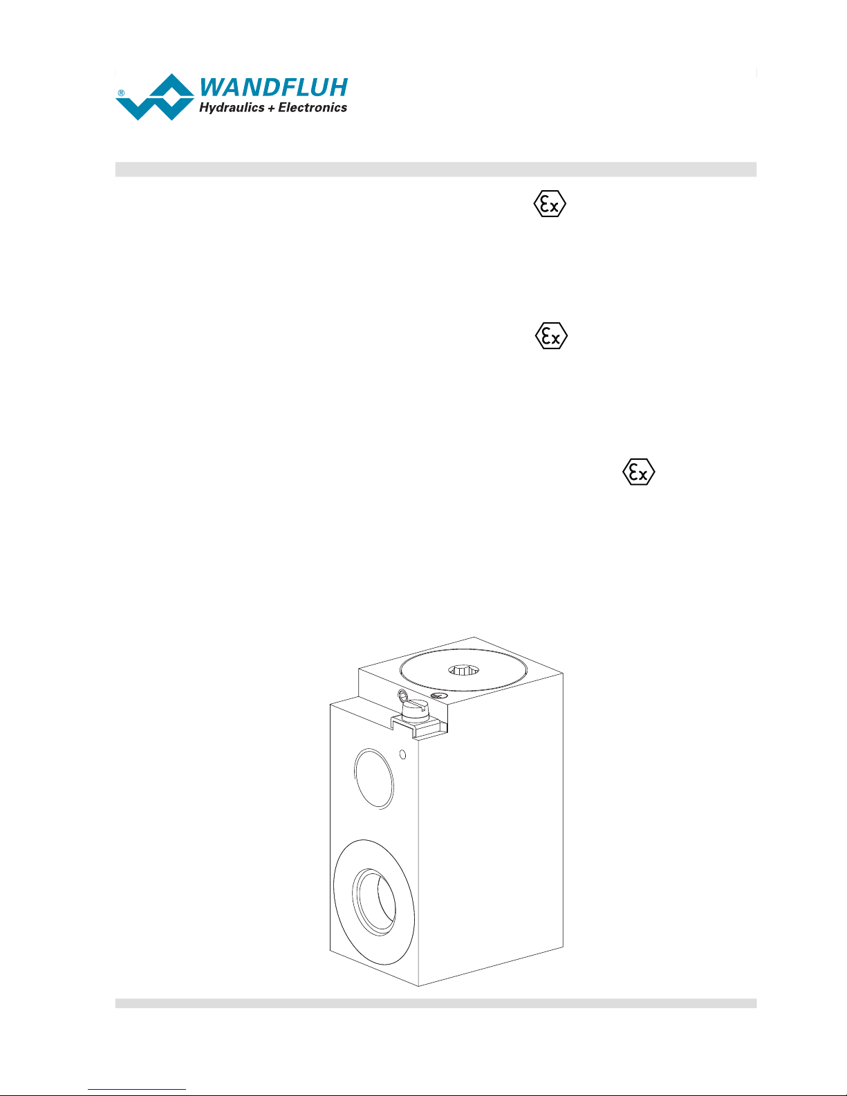
Magnetspule
Installations- und Betriebsanleitung
EU – Konformitätserklärung
Solenoid coil
Installation and operating instructions
EU – Declaration of conformity
Bobine électromagnétique
Instruction dʼinstallation et de mise en service
Déclaration de conformité – EU
Typ / Type / Type: MKY45/18x60-**/L*-*-*/* #*
© Wandfluh AG Frutigen 2018
Page 2
Deutsch
Wandfluh AG E-mail: sales@wandfluh.com Seite 2/36
Postfach Internet www.wandfluh.com Artikel Nr. 990.8001
CH-3714 Frutigen Ausgabe 18 25
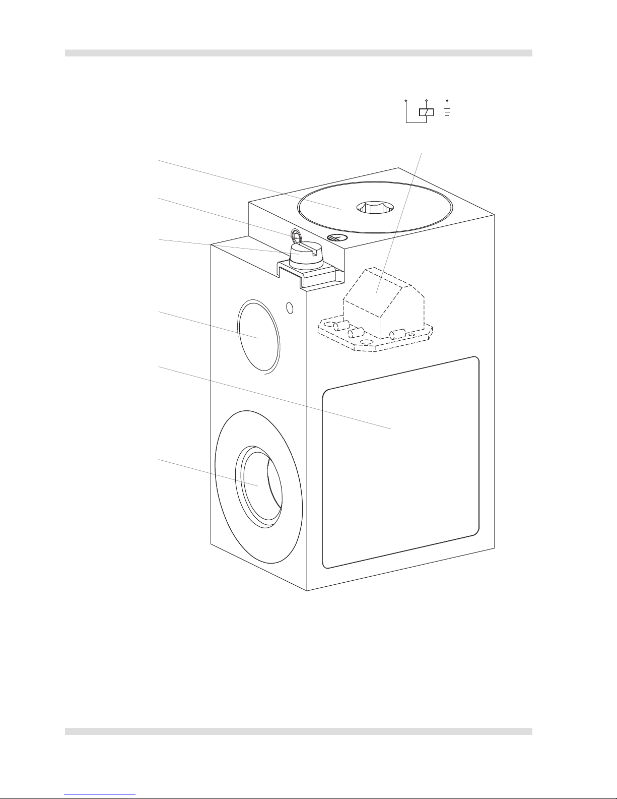
Gesamtansicht
1. Typenschild
2. Spuleninnendurchmesser
3. Gewinde Anschlussverschraubung
4. Erdungsanschluss
5. Gehäusedeckel
6. Anschlussklemme
7. Sicherungsschraube
2
1
3
4
5
6
1 2 PE
7
MD = 40 Nm
Page 3
Deutsch
Wandfluh AG E-mail: sales@wandfluh.com Seite 3/36
Postfach Internet www.wandfluh.com Artikel Nr. 990.8001
CH-3714 Frutigen Ausgabe 18 25
1 Sicherheit
Bestimmungsgemässe Verwendung
Magnetspulen der Typen MKY45/18x60-**/L*-*-*/* #* dienen zusammen mit Ankerrohren zur Betätigung von
Ventilen. Der zum Ventil passende Magnetspulentyp sollte mit dem Magnethersteller oder seinem Repräsentanten ausgewählt werden. Ventilseitig müssen die für die Magnetspule geforderten Einbaubedingungen sichergestellt sein.
Die Magnetspulen sind bescheinigt mit:
• EU-Baumusterprüfbescheinigung PTB 07 ATEX 1023 als Geräte der Gruppe II, Kategorien 2G und 2D. Sie
sind vorgesehen für den Einsatz in Bereichen mit explosionsfähigen Gas-, Dampf-, Nebel-Luftgemischen der
Zonen 1 und 2 sowie in Staub-Luftgemischen der Zonen 21 und 22.
• IECEx Certificate of Conformity IECEx PTB 10.0020 als Geräte der Gruppen IIC und IIIC. Sie sind vorgesehen
für den Einsatz in Bereichen mit explosionsfähigen Gas-, Dampf-, Nebel-Luftgemischen gemäss Equipment
Protection Level Gb sowie in Staub-Luftgemischen gemäss Equipment Protection Level Db.
• EAC No.TC: RU C-CH.ГБ06.В.00154
• EU-Baumusterprüfbescheinigung BVS 11 ATEX E 037 als Geräte der Gruppe I Kategorie M2 Equipment
Protection Level Mb.
• IECEx Certificate of Conformity IECEx BVS 11.0018 als Geräte der Gruppe I Kategorie M2 Equipment
Protection Level Mb.
Autorisierte Personen
Die hier beschriebenen Arbeiten dürfen nur durch autorisierte Personen ausgeführt werden.
Autorisiert sind Personen, die mindestens «elektrotechnisch unterwiesen» sind (äquivalent EN 60 204).
Zu dieser Betriebsanleitung
Diese Betriebsanleitung ist ein integrierter Bestandteil des Zertifikats und somit Bestandteil des Produktes. Sie ist
in die entsprechenden Betriebsanleitungen der übergeordneten Anlagen oder Maschinen zu integrieren.
2 Allgemeine Gefahrenhinweise
Während Montage- und Anschlussarbeiten besteht kein Explosionsschutz. Alle Arbeiten dürfen nur durchgeführt werden, wenn keine Gefahr besteht, insbesondere wenn keine explosionsfähige Atmosphäre
vorhanden ist.
Vor Beginn der Anschlussarbeiten und der Demontage ist sicherzustellen, dass die Betriebsspannung
abgeschaltet und vor unbefugtem Wiedereinschalten gesichert ist.
Zur Wahrung des Explosionsschutzes unbedingt Montagehinweise beachten und die «Einbaubedingungen» einhalten. Eine kundenseitige Lackierung ist nur bis zu einer Schichtdicke von 200 µm
zulässig.
3 Gewährleistung
Ein sicherer und störungsfreier Betrieb ist nur gewährleistet, wenn die Anforderungen dieser Betriebsanleitung
vollständig eingehalten werden. Massgebend für geltend machende Rechtsansprüche ist die deutsche Fassung.
Bei Nichtbeachtung wird keine Haftung durch die Wandfluh AG Frutigen übernommen.
Technische Änderungen und Änderungen im Lieferumfang sind vorbehalten.
Page 4
Deutsch
Wandfluh AG E-mail: sales@wandfluh.com Seite 4/36
Postfach Internet www.wandfluh.com Artikel Nr. 990.8001
CH-3714 Frutigen Ausgabe 18 25
Beispiele:
MKY45/18x60-G24/L15 Magnetspule 24 V Gleichstrom, Nennleistung 15 W und
Gewinde für Anschlussverschraubung M20x1,5.
MKY45/18x60-R48/L9-M187 Magnetspule 48 V Wechselstrom, Nennleistung 9 W und
Gewinde für Anschlussverschraubung NPT1/2″.
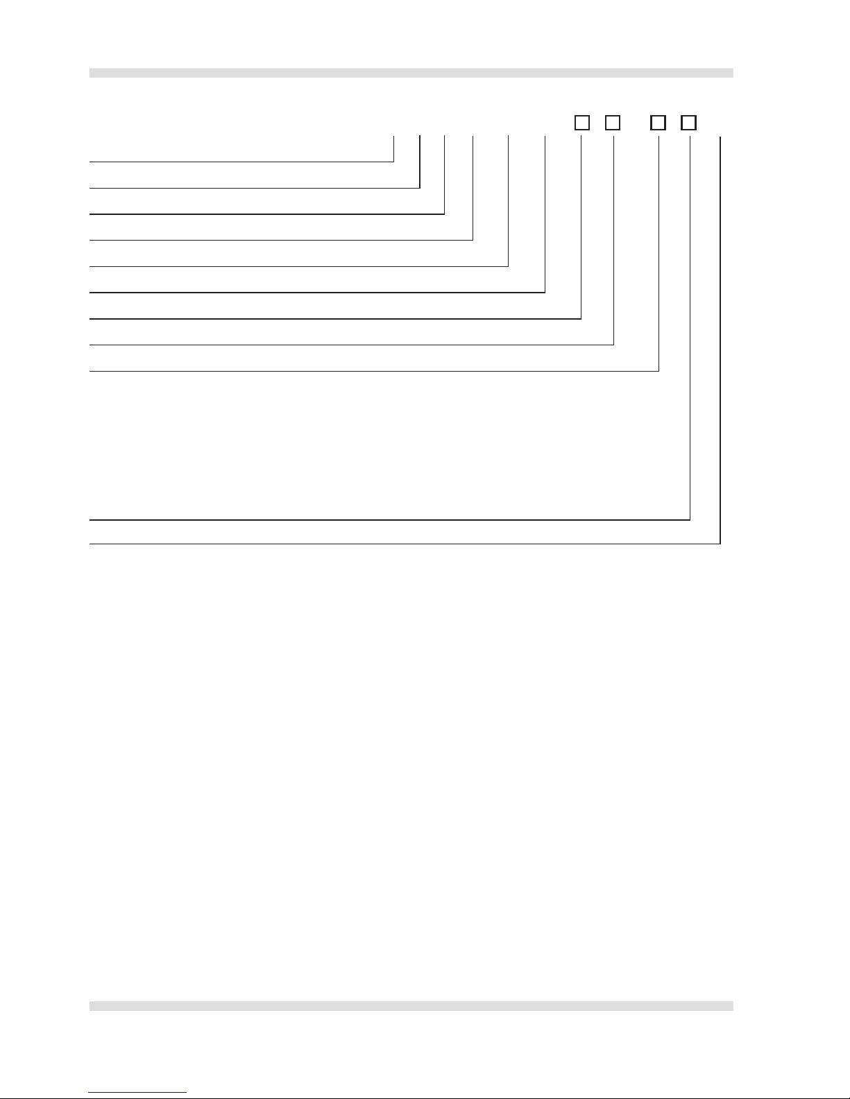
4 Typenbezeichnung
Bei der Option M248, Verstärker, wird eine zusätzliche Montageanleitung mitgeliefert.
Die Installations- und Betriebsanleitung in Russisch finden Sie unter:
http://www.wandfluh.com/downloads => Ex-Schutz => MKY45
M K Y 45 / 18 x 60 - - L
/ #*
Mobilausführung Metallgehäuse
Klemmkasten ohne Kabel
Ex d Ausführung
Gehäusebreite 45 mm
Spuleninnendurchmesser 18 mm
Spulenlänge 60 mm
G = Gleichstrom; R = Wechselstrom
Nennspannung in V
Nennleistung in W
Gewinde für Anschlussverschraubung (KLE) ohne Vermerk: M20x1,5
M187: NPT1/2″
M224: -40 °C Umgebungstemperatur
M238: -60 °C Umgebungstemperatur
M248: Verstärker
M254: Kabeleinführung deckelseitig
M256: Freilaufdiode
M264: Suppressordiode
K9: AISI 316L-Aussenflächen
Änderungsindex (wird vom Werk eingesetzt)
Page 5
Deutsch
Wandfluh AG E-mail: sales@wandfluh.com Seite 5/36
Postfach Internet www.wandfluh.com Artikel Nr. 990.8001
CH-3714 Frutigen Ausgabe 18 25
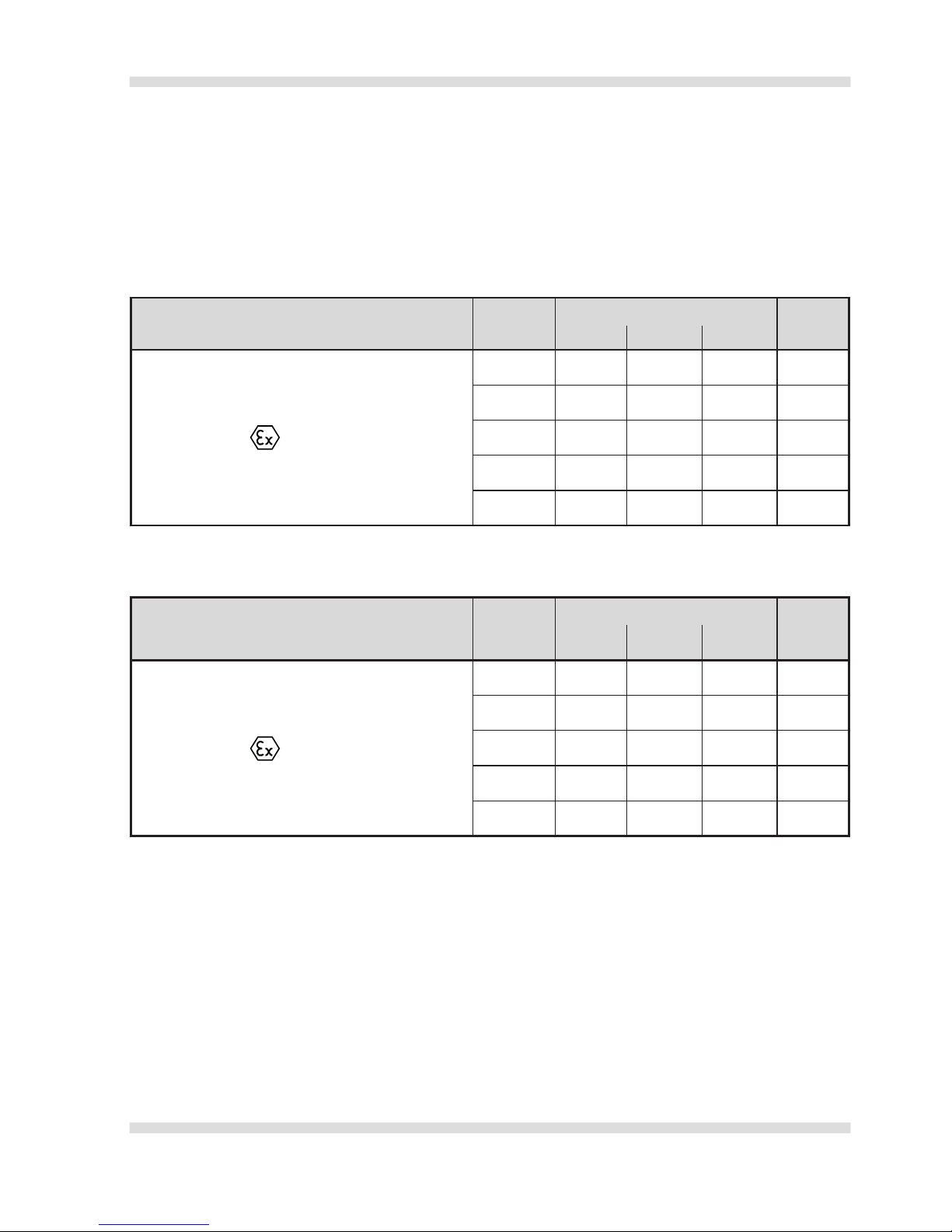
5 Explosionsschutz
Gerätebezeichnung gemäss Richtlinie 2014/34/EU (ATEX), IECEx sowie EAC.
Die Magnetspulen werden gekennzeichnet für einen Nennleistungsbereich von 6-21 Watt und einen Nennspannungsbereich von 12-230 VDC und 24-230 VAC.
Gerätegruppe I, Bergbau:
Magnetspulen in dieser Ausführung dürfen eingesetzt werden in explosionsgefährdeten Bereichen gemäss den
Zertifizierungen:
12 VDC ≤ U
Nenn
< 20 VDC Leistung
Ta min. Ta max.
M238 M224 Standard
ATEX Mining: I M2 Ex db I Mb
≤ 9 Watt -60 °C -40 °C -25 °C +80 °C
≤ 12 Watt -60 °C -40 °C -25 °C +70 °C
≤ 15 Watt -60 °C -40 °C -25 °C +60 °C
≤ 18 Watt -60 °C -40 °C -25 °C +50 °C
≤ 21 Watt -60 °C -40 °C -25 °C +40 °C
Tabelle 1 Kennzeichnungen für Nennspannungen 12 VDC ≤ U
Nenn
< 20 VDC
20 VDC ≤ U
Nenn
≤ 230 VDC
24 VAC ≤ U
Nenn
≤ 230 VAC
Leistung
Ta min. Ta max.
M238 M224 Standard
ATEX Mining: I M2 Ex db I Mb
≤ 9 Watt -60 °C -40 °C -25 °C +90 °C
≤ 12 Watt -60 °C -40 °C -25 °C +80 °C
≤ 15 Watt -60 °C -40 °C -25 °C +70 °C
≤ 18 Watt -60 °C -40 °C -25 °C +60 °C
≤ 21 Watt -60 °C -40 °C -25 °C +50 °C
Tabelle 2 Kennzeichnungen für Nennspannungen 20 VDC ≤ U
Nenn
≤ 230 VDC
24 VAC ≤ U
Nenn
≤ 230 VAC
Page 6
Deutsch
Wandfluh AG E-mail: sales@wandfluh.com Seite 6/36
Postfach Internet www.wandfluh.com Artikel Nr. 990.8001
CH-3714 Frutigen Ausgabe 18 25
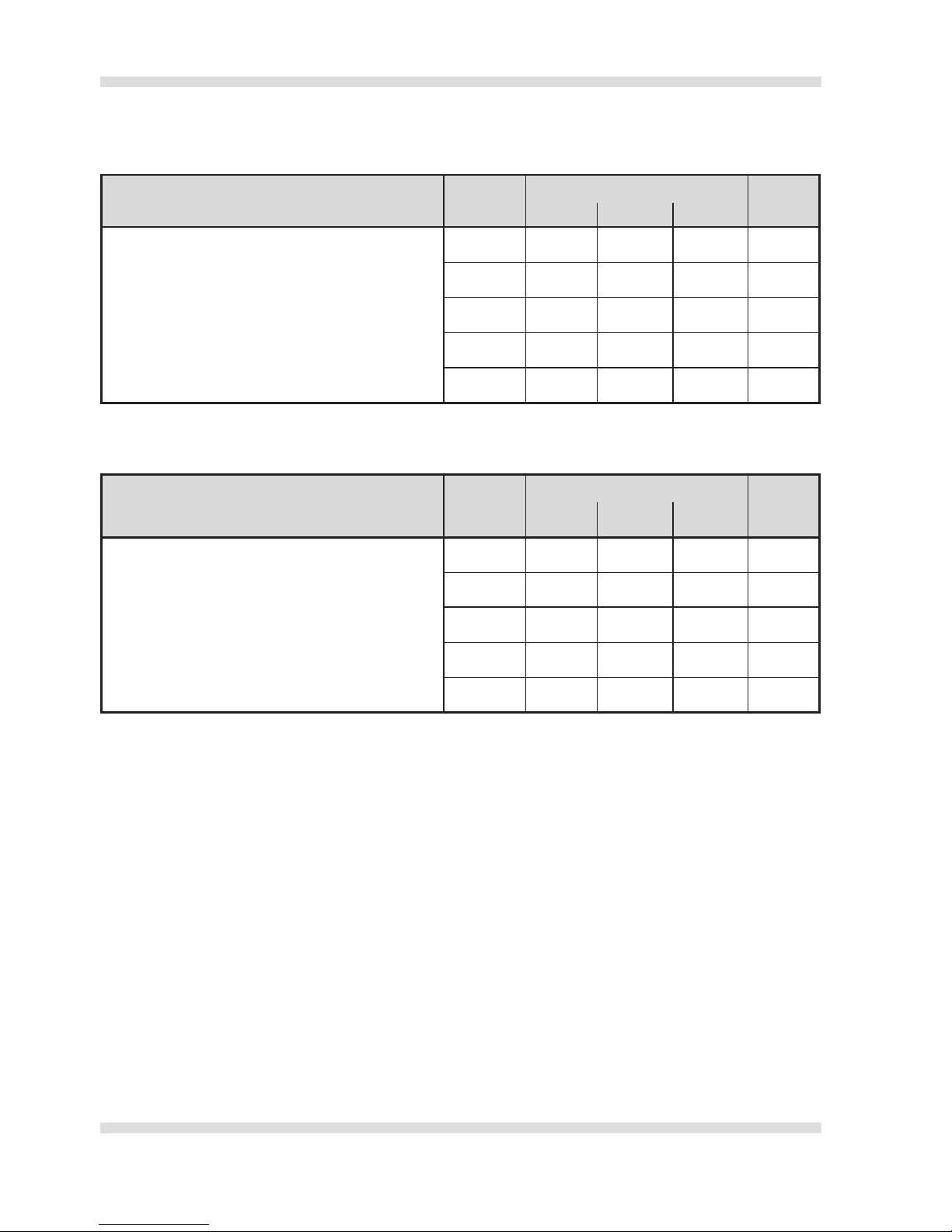
Gerätegruppe I, Bergbau:
Magnetspulen in dieser Ausführung dürfen eingesetzt werden in explosionsgefährdeten Bereichen gemäss den
Zertifizierungen:
12 VDC ≤ U
Nenn
< 20 VDC Leistung
Ta min. Ta max.
M238 M224 Standard
IECEx Mining: Ex db I Mb
≤ 9 Watt -60 °C -40 °C -25 °C +80 °C
≤ 12 Watt -60 °C -40 °C -25 °C +70 °C
≤ 15 Watt -60 °C -40 °C -25 °C +60 °C
≤ 18 Watt -60 °C -40 °C -25 °C +50 °C
≤ 21 Watt -60 °C -40 °C -25 °C +40 °C
Tabelle 1 Kennzeichnungen für Nennspannungen 12 VDC ≤ U
Nenn
< 20 VDC
20 VDC ≤ U
Nenn
≤ 230 VDC
24 VAC ≤ U
Nenn
≤ 230 VAC
Leistung
Ta min. Ta max.
M238 M224 Standard
IECEx Mining: Ex db I Mb
≤ 9 Watt -60 °C -40 °C -25 °C +90 °C
≤ 12 Watt -60 °C -40 °C -25 °C +80 °C
≤ 15 Watt -60 °C -40 °C -25 °C +70 °C
≤ 18 Watt -60 °C -40 °C -25 °C +60 °C
≤ 21 Watt -60 °C -40 °C -25 °C +50 °C
Tabelle 2 Kennzeichnungen für Nennspannungen 20 VDC ≤ U
Nenn
≤ 230 VDC
24 VAC ≤ U
Nenn
≤ 230 VAC
Page 7

Deutsch
Wandfluh AG E-mail: sales@wandfluh.com Seite 7/36
Postfach Internet www.wandfluh.com Artikel Nr. 990.8001
CH-3714 Frutigen Ausgabe 18 25
Gerätegruppe II, übrige Bereiche:
Magnetspulen in dieser Ausführung dürfen eingesetzt werden in explosionsgefährdeten Bereichen gemäss den
Zertifizierungen:
12 VDC ≤ U
Nenn
< 20 VDC Leistung
Ta min. Ta max.
M238 M224
Standard
ATEX: II 2 G Ex db IIC T6 Gb
ATEX: II 2 D Ex tb IIIC T80 °C Db
IECEx: Ex db IIC T6 Gb
IECEx: Ex tb IIIC T80 °C Db
EAC: 1 Ex d IIC T6/T4
≤ 8 Watt -60 °C -40 °C -25 °C +40 °C
ATEX: II 2 G Ex db IIC T4 Gb
ATEX: II 2 D Ex tb IIIC T130 °C Db
IECEx: Ex db IIC T4 Gb
IECEx: Ex tb IIIC T130 °C Db
EAC: 1 Ex d IIC T6/T4
≤ 9 Watt -60 °C -40 °C -25 °C +80 °C
≤ 12 Watt -60 °C -40 °C -25 °C +70 °C
≤ 15 Watt -60 °C -40 °C -25 °C +60 °C
≤ 18 Watt -60 °C -40 °C -25 °C +50 °C
≤ 21 Watt -60 °C -40 °C -25 °C +40 °C
Tabelle 1 Kennzeichnungen für Nennspannungen 12 VDC ≤ U
Nenn
< 20 VDC
20 VDC ≤ U
Nenn
≤ 230 VDC
24 VAC ≤ U
Nenn
≤ 230 VAC
Leistung
Ta min. Ta max.
M238 M224
Standard
ATEX: II 2 G Ex db IIC T6 Gb
ATEX: II 2 D Ex tb IIIC T80 °C Db
IECEx: Ex db IIC T6 Gb
IECEx: Ex tb IIIC T80 °C Db
EAC: 1 Ex d IIC T6/T4
≤ 9 Watt -60 °C -40 °C -25 °C +40 °C
ATEX: II 2 G Ex db IIC T4 Gb
ATEX: II 2 D Ex tb IIIC T130 °C Db
IECEx: Ex db IIC T4 Gb
IECEx: Ex tb IIIC T130 °C Db
EAC: 1 Ex d IIC T6/T4
≤ 9 Watt -60 °C -40 °C -25 °C +90 °C
≤ 12 Watt -60 °C -40 °C -25 °C +80 °C
≤ 15 Watt -60 °C -40 °C -25 °C +70 °C
≤ 18 Watt -60 °C -40 °C -25 °C +60 °C
≤ 21 Watt -60 °C -40 °C -25 °C +50 °C
Tabelle 2 Kennzeichnungen für Nennspannungen 20 VDC ≤ U
Nenn
≤ 230 VDC
24 VAC ≤ U
Nenn
≤ 230 VAC
Page 8
Deutsch
Wandfluh AG E-mail: sales@wandfluh.com Seite 8/36
Postfach Internet www.wandfluh.com Artikel Nr. 990.8001
CH-3714 Frutigen Ausgabe 18 25
6 Technische Daten
Nennspannung ...........................................................................................................................Gemäss Typenschild
Maximale zulässige Betriebsspannung ............................................................................... Nennspannung +10 %
Nennfrequenz ....................................................................................................................Gemäss Typenschild ±2 %
Nennleistung ..............................................................................................................................Gemäss Typenschild
Einschaltdauer .......................................................................................................................... 100 % (Dauerbetrieb)
Relative Luftfeuchtigkeit ............................................................................................... Max. 95 % (nicht betauend)
Schutz gegen Verschmutzung gemäss EN 60 529 ..........................................................................................IP65
................................................................................................. IP66/67 nur mit entsprechender Kabelverschraubung
7 Betriebsbedingungen
Stromversorgung
• Maximal zulässige Restwelligkeit: +/-10 % der Nennspannung.
• Zulässige Spannungsimpulse:
- Spitzenwer t ≤ 1000 V
- Zeitdauer ≤ 1,5 ms
• Zulässige Werte für Spannungsunterbrechung/Spannungsunterschreitung sind abhängig vom Ventil
(evtl. bei Hersteller erfragen).
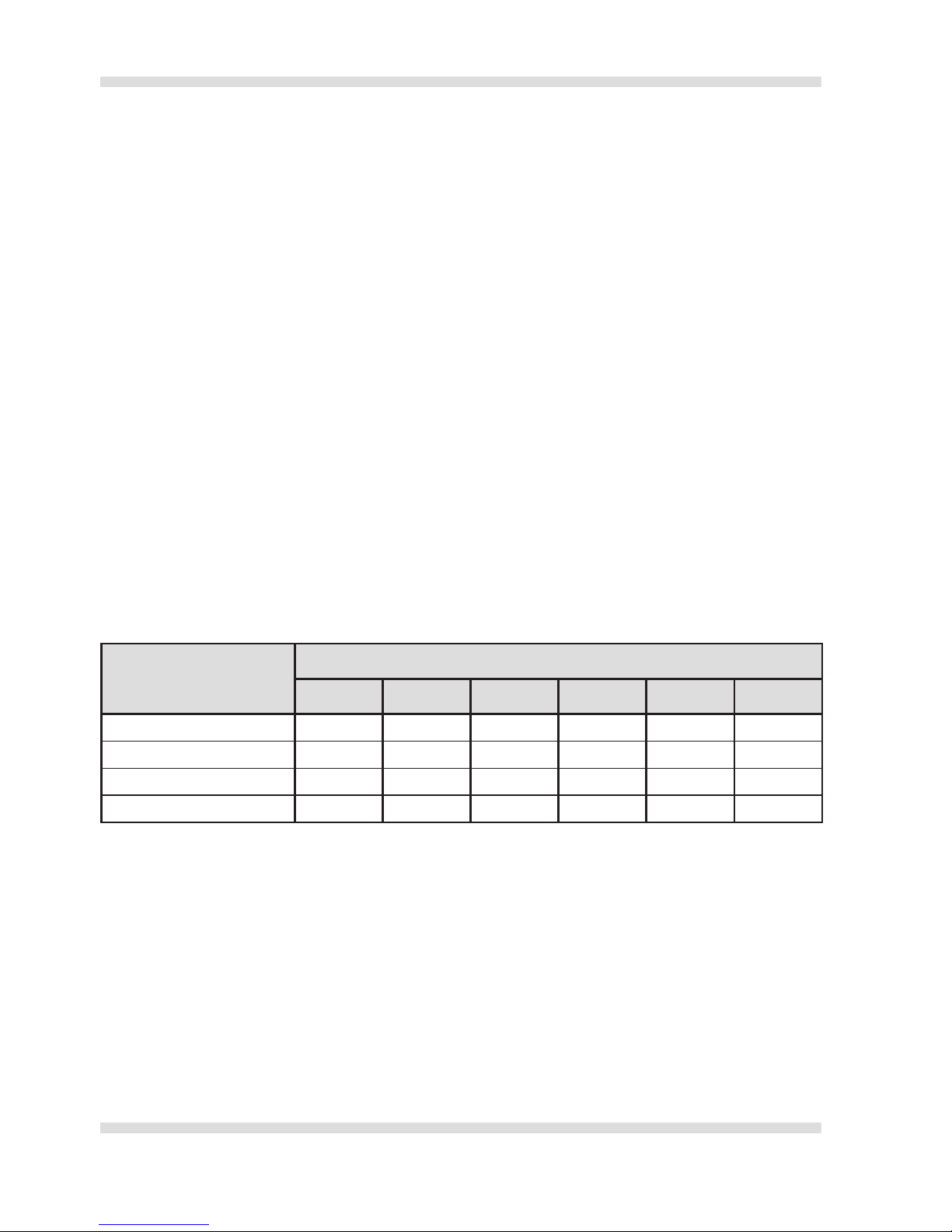
•
Jeder Magnetspule muss als Kurzschlussschutz eine ihrem Bemessungsstrom entsprechende Sicherung (max.
3 x I
Nenn
, empfohlen 2 x I
Nenn
nach IEC 60127-2-1) bzw. ein thermischer Überstromauslöser mit Kurzschluss- und
thermischer Schnellauslösung (Einstellung auf Bemessungsstrom) vorgeschaltet werden.
Der Bemessungsstrom der Sicherung darf ausserdem nicht grösser sein als der Kurzschlussstrom der Ver-
sorgungsquelle.
Nennspannung
Nennleistung
6 Watt 9 Watt 12 Watt 15 Watt 18 Watt 21 Watt
12 VDC 1,0 A 1,6 A 2,0 A 2,5 A 3,15 A 4,0 A
24 VDC 0,5 A 0,8 A 1,0 A 1,25 A 1,6 A 2,0 A
115 VAC 0,125 A 0,2 A 0,25 A 0,315 A 0,4 A 0,4 A
230 VAC 0,063 A 0,1 A 0,125 A 0,160 A 0,2 A 0,2 A
Tabelle 3 Empfohlener Bemessungsstrom für Sicherungseinsätze
Mediumstemperatur im Ventil (sofern nicht im Ventildatenblatt weiter eingeschränkt):
• Stan dard: -25 °C b is 70 °C
• Option M224: -40 °C bis 70 °C
• Option M238: -60 °C bis 70 °C
Erhöhte Anforderungen
Magnetspulen in dieser Ausführung sind vorgesehen für den Einsatz in stationärer Industriehydraulik sowie
Mobilhydraulik.
Sie wurden erfolgreich auf Temperaturschock, Vibration und mechanischem Schock geprüft.
Dennoch garantiert der Hersteller nicht die Eignung und übernimmt keine Verantwortung für den Einsatz unter
extremen Bedingungen.
Page 9
Deutsch
Wandfluh AG E-mail: sales@wandfluh.com Seite 9/36
Postfach Internet www.wandfluh.com Artikel Nr. 990.8001
CH-3714 Frutigen Ausgabe 18 25
8 Montage / Inbetriebnahme / Demontage
Vor Beginn müssen «Sicherheit» und «Allgemeine Gefahrenhinweise» gelesen und verstanden worden sein.
Während Montage- und Anschlussarbeiten besteht kein Explosionsschutz. Alle Arbeiten dürfen nur durchgeführt
werden, wenn keine Gefahr besteht, insbesondere wenn keine explosionsfähige Atmosphäre vorhanden ist.
Montage
1.
Magnetspule über das Ankerrohr des Ventils schieben. Das Ankerrohr muss aus Stahl sein und einen Durchmesser von min. 17.8 mm aufweisen. Es darf auf einer Länge von max. 15 mm einen Durchmesser von
min. 15.9 mm aufweisen.
2. Mit Mutter befestigen.
3. Mutter festziehen bis Verdrehen oder Lösen der Magnetspule durch zu erwartende Erschütterungen nicht
mehr möglich ist.
Anschlussarbeiten
Die Magnetspule ist nur über dafür zugelassene und geeignete Kabel- und Leitungseinführungen bzw. Rohrleitungssysteme anzuschliessen, die mindestens die Schutzklasse IP65 aufweisen. Sie müssen den Anforderungen
der EN 60079-1 Abschnitte 13.1 und 13.2, Druckfeste Kapselung, entsprechen und über eine entsprechende Prüfbescheinigung verfügen.
Kabel- und Leitungseinführungen sowie Verschlussstopfen einfacher Bauart dürfen nicht verwendet werden.
Bei Anschluss der Magnetspule über eine für diesen Zweck zugelassene Rohrleitungseinführung
muss die zugehörige Abdichtungsvorrichtung (Stopping-Box) unmittelbar am Magnetgehäuse
angeordnet sein bzw. in einer Entfernung von maximal 18″ (45cm).
In der Gerätegruppe I, Bergbau, sind feste Rohrleitungssysteme NICHT erlaubt.
1. Deckel öffnen (Innensechskantschlüssel 8 mm).
2. Magnetspulen an Versorgungsspannung anschliessen, Leitungsquerschnitt 0,75-2,5 mm
2
.
3. Bei Umgebungstemperaturen von mehr als 40 °C Kabel oder Leitung mit Grenztemperatur min. 120 °C
verwenden.
4. Potentialausgleich über inneren Schutzleiteranschluss oder äussere Anschlussklemme herstellen.
5. Deckel fest anziehen, Anzugsdrehmoment 40 Nm, um Ex-Schutz zu gewährleisten und Wasserein-
bruch zu vermeiden.
6. Sicherungsschraube fest anziehen.
Inbetriebnahme
Das Gerät darf nur nach Abschluss der vollständigen Montagearbeiten in Betrieb genommen werden gemäss
Einbaubedingungen. Insbesondere der Deckel muss fest montiert und gesichert sein.
Demontage
1. Anschlusskabel demontieren («Allgemeine Gefahrenhinweise» beachten).
2. Befestigungsmutter lösen.
3. Magnetspule von Ankerrohr ziehen (nur im unbestromten Zustand).
Page 10
Deutsch
Wandfluh AG E-mail: sales@wandfluh.com Seite 10/36
Postfach Internet www.wandfluh.com Artikel Nr. 990.8001
CH-3714 Frutigen Ausgabe 18 25
9 Reparatur / Entsorgung
Zur Sicherstellung des Explosionsschutzes dürfen die Magnetspulen nicht repariert werden.
Entsorgen gemäss den Richtlinien des jeweiligen Landes oder an den Hersteller zurücksenden.
10 Einbaubedingungen
Eine kundenseitige Lackierung ist nur bis zu einer Schichtdicke von 200 µm zulässig.
Es ist sicherzustellen, dass die Gewinde M20 und M36 nicht lackiert werden.
Die Magnetspule darf nur in Verbindung mit einem Ankerrohr und einem Ventil betrieben werden.
In Reihenanordnung beeinflussen sich die Magnetspulen gegenseitig und können sich in erhöhtem
Masse erwärmen.
Der Betreiber ist verantwortlich für die Einbausituation und aller sich daraus ergebenden Gefahren. Der Hersteller der Magnetspulen kann nicht haftbar gemacht werden für Gefahren oder Schäden, die aus Nichtbeachtung der
Betriebsanleitung resultieren.
Notizen / Notes / Notes
Page 11
Deutsch
Wandfluh AG E-mail: sales@wandfluh.com Seite 11/36
Postfach Internet www.wandfluh.com Artikel Nr. 990.8001
CH-3714 Frutigen Ausgabe 18 25
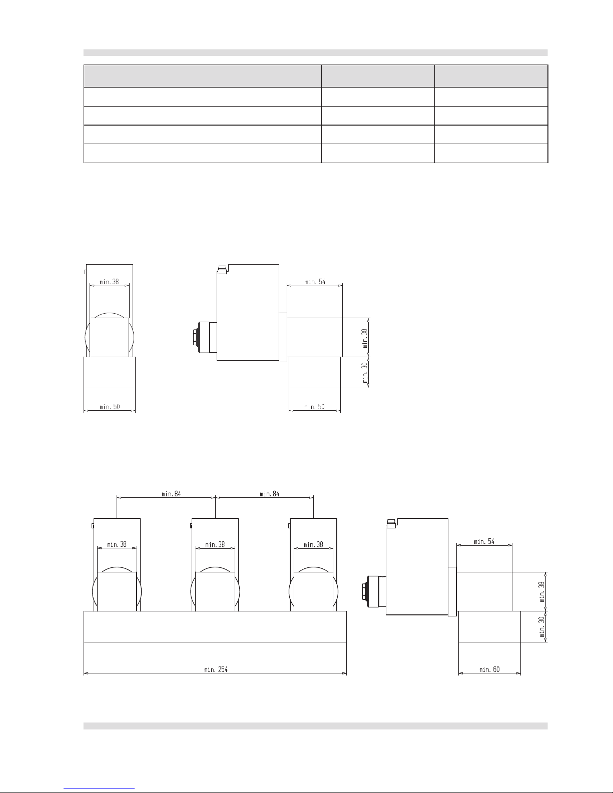
Einzelmontage Reihenmontage
Mindestmasse des Ventilkörpers 38 x 38 x 54 mm 38 x 38 x 54 mm
Mindestmasse der Anschlussplatte 30 x 50 x 50 mm 30 x 60 x 254 mm
Mindestwärmeleitfähigkeit 14 W/(m
●
K) 14 W/(m●K)
Mindestabstand zwischen Ventillängsachsen 84 mm
(Nennmasse in mm)
Page 12

Deutsch
Wandfluh AG E-mail: sales@wandfluh.com Seite 12/36
Postfach Internet www.wandfluh.com Artikel Nr. 990.8001
CH-3714 Frutigen Ausgabe 18 25
EU-Konformitätserklärung
EU-Declaration of conformity
EU-Declaration de Conformite
Wir
We
Nous
Wandfluh AG
Helkenstrasse 13,
CH-3714 Frutigen, Switzerland
Erklären in alleiniger Verantwortung, dass das Produkt
Hereby declare in our sole responsibility, that the product
Declarons de notre seule responsabilite, que le produit
Magnetspule
Solenoid
Bobine électromagnétique
Typ:
Type:
Désignation:
MKY45/18x60-**/L*-*-*/* #*
Mit der EU-Baumusterprüfbescheinigungen:
Under EU-Type Examination Certificate:
Avec Attestation dʼexamen EU de type:
PTB 07 ATEX 1023
BVS 11 ATEX E 037
Mit der IECEx-Baumusterprüfbescheinigungen:
Under IECEx-Type Examination Certificate:
Avec Attestation dʼexamen IECEx de type:
IECEx PTB 10.0020
IECEx BVS 11.0018
Mit der EAC-Baumusterprüfbescheinigungen:
Under EAC-Type Examination Certificate:
Avec Attestation dʼexamen EAC de type:
RU C-CH.ГБ06.В.00154
Auf das sich diese Erklärung bezieht, mit den folgenden Normen oder normativen Dokumenten übereinstimmt
Which is the subject of this declaration, is in conformity with the following standards or normative documents
Auquel cette declaration se rapporte, est conforme aux normes ou aux documents normatifs suivants
Bestimmungen der Richtlinie
Terms of the directive
Prescription de la directive
Nummer sowie Ausgabedatum der Norm
Number and date of issue of the standard
Numero ainsi que date dʼemission des normes
2014/34/EU ATEX-Richtlinie
2014/34/EU ATEX Directive
2014/34/EU Directive ATEX
EN 60079-0: 2012
EN 60079-1: 2014
EN 60079-31: 2014
Qualitätssicherung Produktion:
Production quality assessment:
Assurance qualité production:
SEV 16 ATEX 4130
CH/SEV/QAR16.0001
Erteilt durch benannten Stellen:
Issued by notified bodies:
Délivré par Iʼorganisme de certification:
electrosuisse 1258
Frutigen, 5. September 2017
Ort und Datum
Place and date
Lieu et date
Tobias Krause
Leiter Technik
Head of technical department
Directeur du department technique
Erich Schmid
Leiter Qualitätsmanagement
Director quality management dept.
Directeur dept. assurance de qualité
Page 13

Wandfluh AG E-mail: sales@wandfluh.com Page 13/36
Postfach Internet www.wandfluh.com Article Nr. 990.8001
CH-3714 Frutigen Edition 18 25
English
Magnetspule
Installations- und Betriebsanleitung
EU – Konformitätserklärung
Solenoid coil
Installation and operating instructions
EU – Declaration of conformity
Bobine électromagnétique
Instruction dʼinstallation et de mise en service
Déclaration de conformité – EU
Typ / Type / Type: MKY45/18x60-**/L*-*-*/* #*
© Wandfluh AG Frutigen 2018
Page 14

Wandfluh AG E-mail: sales@wandfluh.com Page 14/36
Postfach Internet www.wandfluh.com Article Nr. 990.8001
CH-3714 Frutigen Edition 18 25
English
Overall view
1. Name plate
2. Internal coil diameter
3. Thread for screw connection
4. Grounding connection
5. Housing cover
6. Connection terminal
7. Safety bolt
2
1
3
4
5
6
1 2 PE
7
MD = 40 Nm
Page 15

Wandfluh AG E-mail: sales@wandfluh.com Page 15/36
Postfach Internet www.wandfluh.com Article Nr. 990.8001
CH-3714 Frutigen Edition 18 25
English
1 Safety
Use in Line with the Intended Purpose
Solenoid coils of the types MKY45/18x60-**/L*-*-*/* #* together with armature tubes serve for the actuation of valves. The solenoid type matching valve should be selected in conjunction with the solenoid manufacturer or his representative. On the valve side, the installation conditions required for the solenoid coil have to be ensured.
The solenoid coils are certified with:
• The EU-type test certification PTB 07 ATEX 1023 are certified as devices of the group II and the category 2G
and 2D. They are intended for utilisation in zones with explosive gas-, vapour-, mist-air mixtures of the zones
1 and 2 as well as in dust-air mixtures of the zones 21 and 22.
• The IECEx certificate of conformity IECEx PTB 10.0020 as devices of the groups IIC and IIIC. They are in-
tended for utilisation in zones with explosive gas-, vapour-, mist-air mixtures in accordance with equipment
protection level Gb as well as in dust-air mixtures in accordance with equipment protection level Db.
• EAC No.TC: RU C-CH.ГБ06.В.00154
• The EU-type test certification BVS 11 ATEX E 037 are certified as devices of the group I and the category M2
equipment protection level Mb.
• The IECEx certificate of conformity IECEx BVS 11.0018 as devices of the groups I and the category M2 equip-
ment protection level Mb.
Authorised Persons
The work described here must only be carried out by authorised persons. Authorised are persons, who have been
at least «electro-technically instructed» (equivalent to EN 60 204).
About these Operating Instructions
These operating instructions are an integrated part of the certificate and therefore a component of the product.
They have to be integrated in the corresponding operating instructions of the subordinate installation or
machines.
2 General Remarks about Danger
During the installation- and connection- work there is no explosion protection. All works must only be
carried out if there is no danger, in particular if no explosive atmosphere is present.
Prior to starting the connection work and the dismantling, it has to be ensured, that the operating power
is switched off and is secured against unauthorised switching on.
For maintaining the explosion protection, do not fail to observe the installation remarks and adhere to
the «Installation Conditions». Customer specific coating is only permitted if thickness does not exceed
200 µm.
3 Guarantee
A safe operation without any problems is only assured, if the requirements of these operating instructions are completely adhered to. Decisive for the assertion of legal rights is the German language version. In case of non-observance, Wandfluh AG assumes no liability.
Subject of technical changes and changes in the scope of delivery.
Page 16

Wandfluh AG E-mail: sales@wandfluh.com Page 16/36
Postfach Internet www.wandfluh.com Article Nr. 990.8001
CH-3714 Frutigen Edition 18 25
English
Examples:
MKY45/18x60-G24/L15 Solenoid coil 24 V direct current, nominal power 15 W and
thread for screw connection M20x1.5
MKY45/18x60-R48/L9-M187 Solenoid coil 48 V alternating current, nominal power 9 W and
thread for screw connection NPT1/2″
4 Type Designations
In case of the option M248, amplifier, additional installation instructions are provided.
The Installation- and Operating Instructions in Russian can be found on:
http://www.wandfluh.com/downloads => Ex-Proof => MKY45
M K Y 45 / 18 x 60 -
- L
/ #*
Mobile version metal housing
Terminal box without cable
Ex d execution
Housing width 45 mm
Internal coil diameter 18 mm
Coil length 60 mm
G = direct current; R = alternating current
Nominal voltage in V
Nominal power in W
Thread for screw connection (KLE) without note: M20x1,5
M187: NPT1/2″
M224: -40 °C Ambient temperature
M238: -60 °C Ambient temperature
M248: Amplifier
M254: Cable gland through the cover
M256: Free-wheeling diode
M264: Suppressor diode
K9: AISI 316L-Bodyshell
Design-Index (Subject to change)
Page 17

Wandfluh AG E-mail: sales@wandfluh.com Page 17/36
Postfach Internet www.wandfluh.com Article Nr. 990.8001
CH-3714 Frutigen Edition 18 25
English
5 Explosion Protection
Device designation in accordance with Directive 2014/34/EU (ATEX), IECEx as well as EAC.
The solenoid coils are identified for a power range of 6-21 Watt and a nominal voltage range of 12-230 VDC and
24-230 VAC.
Device group I, mining:
Solenoid coils of this version may be utilised in explosion hazard areas in accordance with the certifications:
12 VDC ≤ U
Nenn
< 20 VDC Power
Ta min. Ta max.
M238 M224 Standard
ATEX Mining: I M2 Ex db I Mb
≤ 9 Watt -60 °C -40 °C -25 °C +80 °C
≤ 12 Watt -60 °C -40 °C -25 °C +70 °C
≤ 15 Watt -60 °C -40 °C -25 °C +60 °C
≤ 18 Watt -60 °C -40 °C -25 °C +50 °C
≤ 21 Watt -60 °C -40 °C -25 °C +40 °C
Table 1 Identifications for nominal voltages 12 VDC ≤ U
Nom
< 20 VDC
20 VDC ≤ U
Nenn
≤ 230 VDC
24 VAC ≤ U
Nenn
≤ 230 VAC
Power
Ta min. Ta max.
M238 M224 Standard
ATEX Mining: I M2 Ex db I Mb
≤ 9 Watt -60 °C -40 °C -25 °C +90 °C
≤ 12 Watt -60 °C -40 °C -25 °C +80 °C
≤ 15 Watt -60 °C -40 °C -25 °C +70 °C
≤ 18 Watt -60 °C -40 °C -25 °C +60 °C
≤ 21 Watt -60 °C -40 °C -25 °C +50 °C
Table 2 Identifications for nominal voltage 20 VDC ≤ U
Nom
≤ 230 VDC
24 VAC ≤ U
Nom
≤ 230 VAC
Page 18

Wandfluh AG E-mail: sales@wandfluh.com Page 18/36
Postfach Internet www.wandfluh.com Article Nr. 990.8001
CH-3714 Frutigen Edition 18 25
English
Device group I, mining:
Solenoid coils of this version may be utilised in explosion hazard areas in accordance with the certifications:
12 VDC ≤ U
Nenn
< 20 VDC Power
Ta min. Ta max.
M238 M224 Standard
IECEx Mining: Ex db I Mb
≤ 9 Watt -60 °C -40 °C -25 °C +80 °C
≤ 12 Watt -60 °C -40 °C -25 °C +70 °C
≤ 15 Watt -60 °C -40 °C -25 °C +60 °C
≤ 18 Watt -60 °C -40 °C -25 °C +50 °C
≤ 21 Watt -60 °C -40 °C -25 °C +40 °C
Table 1 Identifications for nominal voltages 12 VDC ≤ U
Nom
< 20 VDC
20 VDC ≤ U
Nenn
≤ 230 VDC
24 VAC ≤ U
Nenn
≤ 230 VAC
Power
Ta min. Ta max.
M238 M224 Standard
IECEx Mining: Ex db I Mb
≤ 9 Watt -60 °C -40 °C -25 °C +90 °C
≤ 12 Watt -60 °C -40 °C -25 °C +80 °C
≤ 15 Watt -60 °C -40 °C -25 °C +70 °C
≤ 18 Watt -60 °C -40 °C -25 °C +60 °C
≤ 21 Watt -60 °C -40 °C -25 °C +50 °C
Table 2 Identifications for nominal voltage 20 VDC ≤ U
Nom
≤ 230 VDC
24 VAC ≤ U
Nom
≤ 230 VAC
Page 19

Wandfluh AG E-mail: sales@wandfluh.com Page 19/36
Postfach Internet www.wandfluh.com Article Nr. 990.8001
CH-3714 Frutigen Edition 18 25
English
Device group II, other areas:
Solenoid coils of this version may be utilised in explosion hazard areas in accordance with the certifications:
12 VDC ≤ U
Nenn
< 20 VDC Power
Ta min. Ta max.
M238 M224
Standard
ATEX: II 2 G Ex db IIC T6 Gb
ATEX: II 2 D Ex tb T80 °C Db
IECEx: Ex db IIC T6 Gb
IECEx: Ex tb IIIC T80 °C Db
EAC: 1 Ex d IIC T6/T4
≤ 8 Watt -60 °C -40 °C -25 °C +40 °C
ATEX: II 2 G Ex db IIC T4 Gb
ATEX: II 2 D Ex tb IIIC T130 °C Db
IECEx: Ex db IIC T4 Gb
IECEx: Ex tb IIIC T130 °C Db
EAC: 1 Ex d IIC T6/T4
≤ 9 Watt -60 °C -40 °C -25 °C +80 °C
≤ 12 Watt -60 °C -40 °C -25 °C +70 °C
≤ 15 Watt -60 °C -40 °C -25 °C +60 °C
≤ 18 Watt -60 °C -40 °C -25 °C +50 °C
≤ 21 Watt -60 °C -40 °C -25 °C +40 °C
Table 1 Identifications for nominal voltages 12 VDC ≤ U
Nom
< 20 VDC
20 VDC ≤ U
Nenn
≤ 230 VDC
24 VAC ≤ U
Nenn
≤ 230 VAC
Power
Ta min. Ta max.
M238 M224
Standard
ATEX: II 2 G Ex db IIC T6 Gb
ATEX: II 2 D Ex tb IIIC T80 °C Db
IECEx: Ex db IIC T6 Gb
IECEx: Ex tb IIIC T80 °C Db
EAC: 1 Ex d IIC T6/T4
≤ 9 Watt -60 °C -40 °C -25 °C +40 °C
ATEX: II 2 G Ex db IIC T4 Gb
ATEX: II 2 D Ex tb IIIC T130 °C Db
IECEx: Ex db IIC T4 Gb
IECEx: Ex tb IIIC T130 °C Db
EAC: 1 Ex d IIC T6/T4
≤ 9 Watt -60 °C -40 °C -25 °C +90 °C
≤ 12 Watt -60 °C -40 °C -25 °C +80 °C
≤ 15 Watt -60 °C -40 °C -25 °C +70 °C
≤ 18 Watt -60 °C -40 °C -25 °C +60 °C
≤ 21 Watt -60 °C -40 °C -25 °C +50 °C
Table 2 Identifications for nominal voltage 20 VDC ≤ U
Nom
≤ 230 VDC
24 VAC ≤ U
Nom
≤ 230 VAC
Page 20

Wandfluh AG E-mail: sales@wandfluh.com Page 20/36
Postfach Internet www.wandfluh.com Article Nr. 990.8001
CH-3714 Frutigen Edition 18 25
English
6 Technical Data
Nominal voltage ...................................................................................................... In accordance with name plate
Maximum admissible operating voltage .......................................................................... Nominal voltage +10 %
Nominal frequency ........................................................................................ In accordance with name plate ±2 %
Nominal power ........................................................................................................ In accordance with name plate
Switched-on time period .......................................................................................... 100 % (continuous operation)
Relative air humidity ................................................................................................. Max. 95 % (not dew-forming)
Protection against contamination with dirt in accordance with EN 60 529 ............................................... IP65
......................................................................................... IP66/67 only with corresponding cable screw connection
7 Operating Conditions
Electric power supply
• Maximum admissible residual ripple: +/-10 % of the nominal voltage.
• Admissible voltage pulses:
- Peak value ≤ 1000 V
- Time duration ≤ 1,5 ms
• Permissible values for voltage interruption / dropping below voltage are dependent on the valve (possibly enquire with the manufacturer).
• Each solenoid must be provided on the line side with a short-circuit protection in the form of a fuse designed
to meet the solenoid current rating (max. 3 x I
Nom
, recommended 2 x I
Nom
in compliance with IEC 60127-2-1)
or a thermal overload trip with instantaneous short-circuit and thermal release (adjusted to match the current
rating).
The current rating of the fuse in addition must not be greater than the short-circuit current of the power supply.
Nominal voltage
Nominal power
6 Watt 9 Watt 12 Watt 15 Watt 18 Watt 21 Watt
12 VDC 1,0 A 1,6 A 2,0 A 2,5 A 3,15 A 4,0 A
24 VDC 0,5 A 0,8 A 1,0 A 1,25 A 1,6 A 2,0 A
115 VAC 0,125 A 0,2 A 0,25 A 0,315 A 0,4 A 0,4 A
230 VAC 0,063 A 0,1 A 0,125 A 0,160 A 0,2 A 0,2 A
Table 3 Recommended current rating for fuse inserts
Fluid temperature for valve (if not otherwise declared in valve datasheet):
• Stan dard: -25 °C to 70 °C
• Option M224: -40 °C to 70 °C
• Option M238: -60 °C to 70 °C
Enhanced requirements
Solenoid coils in this execution are foreseen for utilisation in stationary industrial hydraulics as well as in mobile
hydraulics.
They have been successfully tested for temperature shock, vibration and mechanical shock.
Nonetheless the manufacturer does not guarantee the suitability and assumes no responsibility for the utilisation
under extreme conditions.
Page 21

Wandfluh AG E-mail: sales@wandfluh.com Page 21/36
Postfach Internet www.wandfluh.com Article Nr. 990.8001
CH-3714 Frutigen Edition 18 25
English
8 Installation / Commissioning / Dismantling
Before starting, «Safety» and «General Remarks about Danger» have to have been read and understood.
During the installation- and connection work there is no explosion protection. All works must only be carried out if
there is no danger, in particular if no explosive atmosphere is present.
Installation
1. Slide the solenoid coil over the axial conduit of the valve. The axial conduit has to be made of steel and has to
have a diameter of at least 17.8 mm. Over a length of max 15 mm it may have a diameter of at least 15.9 mm.
2. Fix with nut.
3.
Tighten the nut until a to be anticipated turning or loosening of the solenoid coil by jarring is not possible
anymore.
Connection work
The solenoid coil must only be connected through suitable cable- and conductor entrances, resp. piping systems,
which are certified for this purpose and which have at least the protection class IP65.
They have to correspond to the requirements of the standard EN 60079-1, sections 13.1 and 13.2 and they must
have a corresponding test certificate.
Cable- and line entries as well as sealing plugs of simple design must not be utilised.
In case of a connection of the solenoid coil through a pipe entry certified for this purpose, the
stopping box belonging to it has to be located either directly on the solenoid housing, resp., at a
distance of maximum 18″ (45cm) away from it.
Devices group I, mining: conduit systems are NOT permitted.
1. Open cover (Hexagon spanner 8 mm).
2. Connect solenoid coils to supply voltage, conductor diameter 0,75-2,5 mm
2
.
3. In case of ambient temperatures of more than 40 °C, utilise cable or conductor with a limit temperature
of min. 120 °C.
4. Potential equalisation through internal protective conductor or external connection terminal.
5. Tighten the cover well, tightening torque 40 NM in order to assure ex-protection and to prevent water
penetration.
6. Secure the cover with a hexagon socket screw (Allen screw).
Commissioning
The device must only be commissioned after the completion of all the installation work, in accordance with the
installation conditions.
In particular the cover has to be firmly installed and secured.
Dismantling
1. Remove connection cable (observe «General Remarks on Danger»)
2. Release fixing nut
3. Pull the solenoid coil off the axial conduit (only in a current-free condition).
Page 22

Wandfluh AG E-mail: sales@wandfluh.com Page 22/36
Postfach Internet www.wandfluh.com Article Nr. 990.8001
CH-3714 Frutigen Edition 18 25
English
9 Disposal
For the assurance of the explosion protection, solenoid coils must not be repaired.
Dispose of in accordance with the directives of the respective country or else return to the manufacturer.
10 Installation Conditions
Customer specific coating is only permitted if thickness does not exceed 200 µm.
It is madatory that the threads M20 and M36 are not additionally coated.
The solenoid coil must only be operated in conjunction with an axial conduit and a valve.
In stack assembly the solenoid coils mutually influence one another and can heat up to a greater extent.
The operator is responsible for the installation situation and all dangers resulting from it. The manufacturer cannot
be held responsible for dangers or damage, which result from non-observance of these operating instructions.
Notizen / Notes / Notes
Page 23

Wandfluh AG E-mail: sales@wandfluh.com Page 23/36
Postfach Internet www.wandfluh.com Article Nr. 990.8001
CH-3714 Frutigen Edition 18 25
English
Single assembly Stack assembly
Minimum dimensions of the valve body 38 x 38 x 54 mm 38 x 38 x 54 mm
Minimum dimensions of connection plate 30 x 50 x 50 mm 30 x 60 x 254 mm
Minimum thermal conductivity 14 W/(m
●
K) 14 W/(m●K)
Minimum spacing between longitudinal valve axes 84 mm
(Nominal dimensions in mm)
Page 24

Wandfluh AG E-mail: sales@wandfluh.com Page 24/36
Postfach Internet www.wandfluh.com Article Nr. 990.8001
CH-3714 Frutigen Edition 18 25
English
EU-Konformitätserklärung
EU-Declaration of conformity
EU-Declaration de Conformite
Wir
We
Nous
Wandfluh AG
Helkenstrasse 13,
CH-3714 Frutigen, Switzerland
Erklären in alleiniger Verantwortung, dass das Produkt
Hereby declare in our sole responsibility, that the product
Declarons de notre seule responsabilite, que le produit
Magnetspule
Solenoid
Bobine électromagnétique
Typ:
Type:
Désignation:
MKY45/18x60-**/L*-*-*/* #*
Mit der EU-Baumusterprüfbescheinigungen:
Under EU-Type Examination Certificate:
Avec Attestation dʼexamen EU de type:
PTB 07 ATEX 1023
BVS 11 ATEX E 037
Mit der IECEx-Baumusterprüfbescheinigungen:
Under IECEx-Type Examination Certificate:
Avec Attestation dʼexamen IECEx de type:
IECEx PTB 10.0020
IECEx BVS 11.0018
Mit der EAC-Baumusterprüfbescheinigungen:
Under EAC-Type Examination Certificate:
Avec Attestation dʼexamen EAC de type:
RU C-CH.ГБ06.В.00154
Auf das sich diese Erklärung bezieht, mit den folgenden Normen oder normativen Dokumenten übereinstimmt
Which is the subject of this declaration, is in conformity with the following standards or normative documents
Auquel cette declaration se rapporte, est conforme aux normes ou aux documents normatifs suivants
Bestimmungen der Richtlinie
Terms of the directive
Prescription de la directive
Nummer sowie Ausgabedatum der Norm
Number and date of issue of the standard
Numero ainsi que date dʼemission des normes
2014/34/EU ATEX-Richtlinie
2014/34/EU ATEX Directive
2014/34/EU Directive ATEX
EN 60079-0: 2012
EN 60079-1: 2014
EN 60079-31: 2014
Qualitätssicherung Produktion:
Production quality assessment:
Assurance qualité production:
SEV 16 ATEX 4130
CH/SEV/QAR16.0001
Erteilt durch benannten Stellen:
Issued by notified bodies:
Délivré par Iʼorganisme de certification:
electrosuisse 1258
Frutigen, 5. September 2017
Ort und Datum
Place and date
Lieu et date
Tobias Krause
Leiter Technik
Head of technical department
Directeur du department technique
Erich Schmid
Leiter Qualitätsmanagement
Director quality management dept.
Directeur dept. assurance de qualité
Page 25

Wandfluh AG E-mail: sales@wandfluh.com Page 25/36
Postfach Internet www.wandfluh.com Article Nr. 990.8001
CH-3714 Frutigen Edition 18 25
English
Magnetspule
Installations- und Betriebsanleitung
EU – Konformitätserklärung
Solenoid coil
Installation and operating instructions
EU – Declaration of conformity
Bobine électromagnétique
Instruction dʼinstallation et de mise en service
Déclaration de conformité – EU
Typ / Type / Type: MKY45/18x60-**/L*-*-*/* #*
© Wandfluh AG Frutigen 2018
Page 26

Wandfluh AG E-mail: sales@wandfluh.com Page 26/36
Postfach Internet www.wandfluh.com No. dʼarticle 990.8001
CH-3714 Frutigen Edition 18 25
Français
Vue générale
1. Plaque dʼidentification
2. Diamètre intérieur de la bobine
3. Filetage du raccord de liaison
4. Mise à la terre
5. Couvercle du boîtier
6. Borne de raccordement
7. Vis de sécurité
2
1
3
4
5
6
1 2 PE
7
MD = 40 Nm
Page 27

Wandfluh AG E-mail: sales@wandfluh.com Page 27/36
Postfach Internet www.wandfluh.com No. dʼarticle 990.8001
CH-3714 Frutigen Edition 18 25
Français
1 Sécurité
Utilisation selon la détermination
Les bobines électromagnétiques du type MKY45/18x60-**/L*-*-*/* #* ensemble avec les tubes dʼarmatures sont
utilisées pour lʼactionnement de valves. Le modèle de bobine électromagnétique convenant à la valve devrait être
choisi avec le fabricant de la pièce ou son représentant. Quant à la valve, il faut assurer les conditions nécessaires
pour le montage de la bobine électromagnétique.
Les bobines électromagnétiques sont homologuées par:
• Le certificat de contrôle des modèles types EU PTB 07 ATEX 1023 comme appareils du groupe II et de la
catégorie 2G et 2D, et donc indiquées pour le service dans les secteurs avec des mélanges déflagrants air,
gaz, vapeur, brouillard des zones 1 et 2 ainsi que dans les mélanges air-poussière des zones 21 et 22.
• Le IECEx certificate of conformity IECEx PTB 10.0020 comme appareils des groupes IIC et IIIC. Elles sont
prévues pour le service dans les secteurs avec des mélanges déflagrants air-, gaz, vapeur, brouillard selon le
equipment protection level Gb ainsi que des mélanges air-poussière selon le equipment protection level Db.
• EAC No.TC: RU C-CH.ГБ06.В.00154
• Le certificat de contrôle des modèles types EU BVS 11 ATEX E 037 comme appareils du groupe I et de la
catégorie M2 equipment protection level Mb.
• Le IECEx certificate of conformity IECEx BVS 11.0018 comme appareils du groupe I et de la catégorie M2 equip-
ment protection level Mb.
Personnes autorisées
Les travaux mentionnés ici ne peuvent être exécutés que par des personnes autorisées. Les personnes autorisées sont celles qui sont au minimum «instruites en électrotechnique» (équivalent à EN 60 204).
Concernant cette instruction de service
Cette instruction de service est une partie constituante du certificat et donc un composant du produit. Elle est à in-
tégrer dans les instructions de service correspondantes des installations ou machines dʼordre supérieur.
2 Remarques générales de danger
Il nʼy a pas de protection antidéflagrante pendant les travaux de montage ou dʼentretien. Tous les
travaux sont à effectuer seulement en lʼabsence de danger, en particulier quand il nʼy a pas dʼatmos-
phère explosive.
Il faut sʼassurer avant le début des travaux de raccordement ou de démontage que la tension de service
est déclenchée et assurée contre un réenclenchement intempestif.
Il faut respecter absolument les instructions de montage et les «conditions de mise en place» pour
assurer la protection antidéflagrante. Peinture spécifique par le client est autorisée jusquʼà une
épaisseur de 200 µm.
3 Prestation de garantie
Un service sûr et sans panne est seulement garanti si les exigences de cette mise en service sont entièrement
tenues. La version allemande est déterminante pour des prétentions juridiques valables. En cas de non-obser-
vation, Wandfluh AG Frutigen nʼassure aucune responsabilité.
Sous réservé de modifications techniques et de modifications de la définition des fournitures.
Page 28

Wandfluh AG E-mail: sales@wandfluh.com Page 28/36
Postfach Internet www.wandfluh.com No. dʼarticle 990.8001
CH-3714 Frutigen Edition 18 25
Français
Exemples:
MKY45/18x60-G24/L15 Bobine électromagnétique 24 V courant continu,
puissance nominale 15 W
et filetage du raccord de liaison M20x1,5.
MKY45/18x60-R48/L9-M187 Bobine électromagnétique 48 V courant alternatif,
puissance nominale 9 W
et filetage du raccord de liaison NPT1/2″.
4 Désignation du modèle
Une instruction de montage supplémentaires est livrée avec lʼoption M248, amplificateur.
Lʼinstruction dʼinstallation et de mise en service en russe se trouve sur:
http://www.wandfluh.com/downloads => Ex-protection => MKY45
M K Y 45 / 18 x 60 - - L
/ #*
Boîtier métal exécution mobile
Boîte à bornes sans câble
Ex d execution
Largeur du boîtier 45 mm
Diamètre intérieur de la bobine 18 mm
Longueur de la bobine 60 mm
G = courant continu; R = courant alternatif
Tension nominale en V
Puissance nominale en W
Filetage du raccord de liaison (KLE) sans indice: M20x1,5
M187: NPT1/2″
M224: -40 °C la température ambiante
M238: -60 °C la température ambiante
M248: Amplificateur
M254: Le passage du câble par le couvercle
M256: Diode de roue libre
M264: Diode dʼextinction
K9: AISI 316L-Revêtement
Indice de modification (déterminé par l’usine)
Page 29

Wandfluh AG E-mail: sales@wandfluh.com Page 29/36
Postfach Internet www.wandfluh.com No. dʼarticle 990.8001
CH-3714 Frutigen Edition 18 25
Français
5 Protection antidéflagrante
Désignation de lʼappareil selon directive 2014/34/EU (ATEX), IECEx aussi bien que EAC.
Les bobines électro-magnétiques sont désignées pour une plage de puissance de 6-21 Watt et une plage de
tension de 12-230 VDC et 24-230 VAC.
Groupe dʼappareils I, mines:
Les bobines électro-magnétiques de cette exécution peuvent être mises en service dans les domaines avec
danger dʼexplosion selon les certifications:
12 VDC ≤ U
Nenn
< 20 VDC Puissance
Ta min. Ta max.
M238 M224 Standard
ATEX Mining: I M2 Ex db I Mb
≤ 9 Watt -60 °C -40 °C -25 °C +80 °C
≤ 12 Watt -60 °C -40 °C -25 °C +70 °C
≤ 15 Watt -60 °C -40 °C -25 °C +60 °C
≤ 18 Watt -60 °C -40 °C -25 °C +50 °C
≤ 21 Watt -60 °C -40 °C -25 °C +40 °C
Tableau 1 Désignations pour les tensions nominales 12 VDC ≤ U
Nom
< 20 VDC
20 VDC ≤ U
Nenn
≤ 230 VDC
24 VAC ≤ U
Nenn
≤ 230 VAC
Puissance
Ta min. Ta max.
M238 M224 Standard
ATEX Mining: I M2 Ex db I Mb
≤ 9 Watt -60 °C -40 °C -25 °C +90 °C
≤ 12 Watt -60 °C -40 °C -25 °C +80 °C
≤ 15 Watt -60 °C -40 °C -25 °C +70 °C
≤ 18 Watt -60 °C -40 °C -25 °C +60 °C
≤ 21 Watt -60 °C -40 °C -25 °C +50 °C
Tableau 2 Désignations pour les tensions nominales 20 VDC ≤ U
Nom
≤ 230 VDC
24 VAC ≤ U
Nom
≤ 230 VAC
Page 30

Wandfluh AG E-mail: sales@wandfluh.com Page 30/36
Postfach Internet www.wandfluh.com No. dʼarticle 990.8001
CH-3714 Frutigen Edition 18 25
Français
Groupe dʼappareils I, mines:
Les bobines électro-magnétiques de cette exécution peuvent être mises en service dans les domaines avec
danger dʼexplosion selon les certifications:
12 VDC ≤ U
Nenn
< 20 VDC Puissance
Ta min. Ta max.
M238 M224 Standard
IECEx Mining: Ex db I Mb
≤ 9 Watt -60 °C -40 °C -25 °C +80 °C
≤ 12 Watt -60 °C -40 °C -25 °C +70 °C
≤ 15 Watt -60 °C -40 °C -25 °C +60 °C
≤ 18 Watt -60 °C -40 °C -25 °C +50 °C
≤ 21 Watt -60 °C -40 °C -25 °C +40 °C
Tableau 1 Désignations pour les tensions nominales 12 VDC ≤ U
Nom
< 20 VDC
20 VDC ≤ U
Nenn
≤ 230 VDC
24 VAC ≤ U
Nenn
≤ 230 VAC
Puissance
Ta min. Ta max.
M238 M224 Standard
IECEx Mining: Ex db I Mb
≤ 9 Watt -60 °C -40 °C -25 °C +90 °C
≤ 12 Watt -60 °C -40 °C -25 °C +80 °C
≤ 15 Watt -60 °C -40 °C -25 °C +70 °C
≤ 18 Watt -60 °C -40 °C -25 °C +60 °C
≤ 21 Watt -60 °C -40 °C -25 °C +50 °C
Tableau 2 Désignations pour les tensions nominales 20 VDC ≤ U
Nom
≤ 230 VDC
24 VAC ≤ U
Nom
≤ 230 VAC
Page 31

Wandfluh AG E-mail: sales@wandfluh.com Page 31/36
Postfach Internet www.wandfluh.com No. dʼarticle 990.8001
CH-3714 Frutigen Edition 18 25
Français
Groupe dʼappareils II, autres domaines:
Les bobines électro-magnétiques de cette exécution peuvent être mises en service dans les domaines avec
danger dʼexplosion selon les certifications:
12 VDC ≤ U
Nenn
< 20 VDC Puissance
Ta min. Ta max.
M238 M224
Standard
ATEX: II 2 G Ex db IIC T6 Gb
ATEX: II 2 D Ex tb IIIC T80 °C Db
IECEx: Ex db IIC T6 Gb
IECEx: Ex tb IIIC T80 °C Db
EAC: 1 Ex d IIC T6/T4
≤ 8 Watt -60 °C -40 °C -25 °C +40 °C
ATEX: II 2 G Ex db IIC T4 Gb
ATEX: II 2 D Ex tb IIIC T130 °C Db
IECEx: Ex db IIC T4 Gb
IECEx: Ex tb IIIC T130 °C Db
EAC: 1 Ex d IIC T6/T4
≤ 9 Watt -60 °C -40 °C -25 °C +80 °C
≤ 12 Watt -60 °C -40 °C -25 °C +70 °C
≤ 15 Watt -60 °C -40 °C -25 °C +60 °C
≤ 18 Watt -60 °C -40 °C -25 °C +50 °C
≤ 21 Watt -60 °C -40 °C -25 °C +40 °C
Tableau 1 Désignations pour les tensions nominales 12 VDC ≤ U
Nom
< 20 VDC
20 VDC ≤ U
Nenn
≤ 230 VDC
24 VAC ≤ U
Nenn
≤ 230 VAC
Puissance
Ta min. Ta max.
M238 M224
Standard
ATEX: II 2 G Ex db IIC T6 Gb
ATEX: II 2 D Ex tb IIIC T80 °C Db
IECEx: Ex db IIC T6 Gb
IECEx: Ex tb IIIC T80 °C Db
EAC: 1 Ex d IIC T6/T4
≤ 9 Watt -60 °C -40 °C -25 °C +40 °C
ATEX: II 2 G Ex db IIC T4 Gb
ATEX: II 2 D Ex tb IIIC T130 °C Db
IECEx: Ex db IIC T4 Gb
IECEx: Ex tb IIIC T130 °C Db
EAC: 1 Ex d IIC T6/T4
≤ 9 Watt -60 °C -40 °C -25 °C +90 °C
≤ 12 Watt -60 °C -40 °C -25 °C +80 °C
≤ 15 Watt -60 °C -40 °C -25 °C +70 °C
≤ 18 Watt -60 °C -40 °C -25 °C +60 °C
≤ 21 Watt -60 °C -40 °C -25 °C +50 °C
Tableau 2 Désignations pour les tensions nominales 20 VDC ≤ U
Nom
≤ 230 VDC
24 VAC ≤ U
Nom
≤ 230 VAC
Page 32

Wandfluh AG E-mail: sales@wandfluh.com Page 32/36
Postfach Internet www.wandfluh.com No. dʼarticle 990.8001
CH-3714 Frutigen Edition 18 25
Français
6 Données techniques
Tension nominale ...............................................................................................................................Selon plaque
Tension nominal max. autorisée ..................................................................................... Tension nominale +10 %
Fréquence nominale.................................................................................................................. Selon plaque ±2 %
Puissance nominale ...........................................................................................................................Selon plaque
Durée dʼenclenchement .....................................................................................................100 % (service continu)
Humidité relative de lʼair ................................................................................................... Max. 95 % (sans rosée)
Protection contre lʼencrassement selon EN 60 529 ..................................................................................... IP65
.........................................................................................IP66/67 seulement avec raccord de câble correspondant
7 Conditions de service
Alimentation en courant
• Ondulation résiduelle max.: +/-10 % de la tension nominale.
• Impulsions de tension admissibles:
- Valeur de pointe ≤1000 V
- Durée ≤1,5 ms
• Les valeurs admissibles dʼinterruption ou de dépassement inférieur de tension dépendent de la valve (év. se
renseigner chez le fabricant).
• Chaque bobine électromagnétique doit être protégée contre les court-circuits au moyen dʼun fusible corres-
pondant au courant assigné de la bobine (max. 3x I
Nom.
, recomandé 2x I
Nom
selon IEC 60127-2-1), respecti-
vement par un déclencheur de surintensité thermique avec déclenchement rapide de court-circuit et thermi-
que (réglage dʼaprès le courant assigné).
Le courant assigné du fusible ne doit pas être supérieur au courant de court-circuit de la source dʼalimentation.
Tension nominale
Puissance nominale
6 Watt 9 Watt 12 Watt 15 Watt 18 Watt 21 Watt
12 VDC 1,0 A 1,6 A 2,0 A 2,5 A 3,15 A 4,0 A
24 VDC 0,5 A 0,8 A 1,0 A 1,25 A 1,6 A 2,0 A
115 VAC 0,125 A 0,2 A 0,25 A 0,315 A 0,4 A 0,4 A
230 VAC 0,063 A 0,1 A 0,125 A 0,160 A 0,2 A 0,2 A
Tableau 3 Courant de dimensionnement recommandé pour les fusibles de sécurité
Température du fluide pour le distributeur (si pas déjà mentionné dans la fiche technique du distributeur):
• Standard: de -25 °C à 70 °C
• Option M224: de -40 °C à 70 °C
• Option M238: de -60 °C à 70 °C
Exigences plus élevées
Les bobines électro-magnétiques de cette exécution sont prévues pour le service en hydraulique industrielle
stationnaire ainsi que lʼhydraulique mobile.
Elles ont été éprouvées avec succès aux chocs de température, aux vibrations et aux chocs mécaniques.
Toutefois le fabricant ne garantit pas lʼaptitude et ne prend aucune responsabilité pour la mise en service sous des
conditions extrêmes.
Page 33

Wandfluh AG E-mail: sales@wandfluh.com Page 33/36
Postfach Internet www.wandfluh.com No. dʼarticle 990.8001
CH-3714 Frutigen Edition 18 25
Français
8 Montage / mise en service / démontage
Avant tout travail, il faut lire et comprendre les rubriques «Sécurité» et «Remarques générales de danger».
Il nʼy a pas de protection antidéflagrante pendant les travaux de montage ou dʼentretien. Tous les travaux sont à
effectuer seulement en lʼabsence de danger, en particulier quand il nʼy a pas dʼatmosphère explosive.
Montage
1. Introduire et glisser la bobine électromagnétique sur le tube du noyau de la valve. Le tube du noyau doit être
en acier et présenter un diamètre de 17,8 mm. Il peut avoir un diamètre de minimal de 15,9 mm sur une longueur maximale de 15 mm.
2. Fixer avec lʼécrou.
3. Serrer lʼécrou jusquʼà ce quʼune rotation ou un desserrage de la bobine ne soit plus possible en raison de
secousses à attendre.
Travaux de raccordement
La bobine électromagnétique est à raccorder uniquement avec des câbles et des passages de câbles, resp. des
systèmes de tuyauterie, qui présentent au moins la classe de protection IP65. Ils doivent satisfaire aux exigences
EN 60079-1 paragraphes 13.1 et 13.2 et disposer de lʼhomologation correspondante.
Les câbles et passages de câble et les bouchons de fermeture de construction simple ne doivent
pas être utilisés.
Lors du raccordement de la bobine par un de ces passages de câble autorisés pour cet emploi,
le dispositif dʼétanchéité rattaché (Stopping-Box) doit se trouver tout près du boîtier de la bobine,
resp. à une distance max. de 18″ (45cm).
Groupe dʼappareils I, mines: Les systèmes de conduites fixes ne sont pas autorisés
1. Ouvrir le couvercle (clé Inbus 8 mm).
2. Raccorder la bobine à la tension dʼalimentation, section des fils 0,75-2,5 mm
2
.
3. Utiliser des câbles ou des fils ayant une température limite de 120 °C min. si la température ambiante
est de plus de 40 °C.
4. Etablir lʼéquilibre de potentiel par le raccordement interne de protection ou par la borne extérieure.
5. Bien serrer le couvercle, couple de serrage 40 Nm, pour garantir la protection antidéflagrante et éviter
les infiltrations dʼeau.
6. Assurer le couvercle avec la vis allen.
Mise en service
Lʼappareil ne peut être mis en service quʼà la fin de tous les travaux de montage exécutés selon les conditions de
montage et de mise en place.
En particulier, le couvercle doit être monté solidement et assuré.
Démontage
1. Démonter le câble de raccordement (respecter les «Remarques générales de danger»).
2. Libérer lʼécrou de fixation.
3. Retirer la bobine du tube de noyau (seulement en état sans tension).
Page 34

Wandfluh AG E-mail: sales@wandfluh.com Page 34/36
Postfach Internet www.wandfluh.com No. dʼarticle 990.8001
CH-3714 Frutigen Edition 18 25
Français
Notizen / Notes / Notes
9 Réparation / élimination
Les bobines électromagnétiques ne doivent pas être réparées, ceci pour assurer la protection anti-déflagrante.
Procéder à lʼélimination selon les directives du pays concerné ou renvoi au fabricant.
10 Conditions de mise en place
Peinture spécifique par le client est autorisée jusquʼà une épaisseur de 200 µm.
Il faut assurer de ne pas peindre les filetages M20 et M36.
La bobine électro-magnétique ne peut être mise en service quʼavec un noyau tubulaire et une valve.
En cas de montage en batterie, les bobines sʼinfluencent mutuellement et peuvent sʼéchauffer considé-
rablement.
Lʼexploitant est responsable de la disposition de montage et des dangers qui peuvent en découler. Le fabricant
des bobines électro-magnétiques ne peut être rendu responsable des dangers ou dommages résultants de la nonobservation de lʼinstruction de service.
Page 35

Wandfluh AG E-mail: sales@wandfluh.com Page 35/36
Postfach Internet www.wandfluh.com No. dʼarticle 990.8001
CH-3714 Frutigen Edition 18 25
Français
Montage séparé Montage en batterie
Masse minimum du corps de valve 38 x 38 x 54 mm 38 x 38 x 54 mm
Masse minimum de lʼembase de raccordement 30 x 50 x 50 mm 30 x 60 x 254 mm
Conductibilité thermique minimale 14 W/(m
●K) 14 W/(m●K)
Distance minimale entre les axes longitudinaux des
valves
84 mm
(cotes nominales en mm)
Page 36

Wandfluh AG E-mail: sales@wandfluh.com Page 36/36
Postfach Internet www.wandfluh.com No. dʼarticle 990.8001
CH-3714 Frutigen Edition 18 25
Français
EU-Konformitätserklärung
EU-Declaration of Conformity
EU-Declaration de Conformite
Wir
We
Nous
Wandfluh AG
Helkenstrasse 13,
CH-3714 Frutigen, Switzerland
Erklären in alleiniger Verantwortung, dass das Produkt
Hereby declare in our sole responsibility, that the product
Declarons de notre seule responsabilite, que le produit
Magnetspule
Solenoid
Bobine électromagnétique
Typ:
Type:
Désignation:
MKY45/18x60-**/L*-*-*/* #*
Mit der EU-Baumusterprüfbescheinigungen:
Under EU-Type Examination Certificate:
Avec Attestation dʼexamen EU de type:
PTB 07 ATEX 1023
BVS 11 ATEX E 037
Mit der IECEx-Baumusterprüfbescheinigungen:
Under IECEx-Type Examination Certificate:
Avec Attestation dʼexamen IECEx de type:
IECEx PTB 10.0020
IECEx BVS 11.0018
Mit der EAC-Baumusterprüfbescheinigungen:
Under EAC-Type Examination Certificate:
Avec Attestation dʼexamen EAC de type:
RU C-CH.ГБ06.В.00154
Auf das sich diese Erklärung bezieht, mit den folgenden Normen oder normativen Dokumenten übereinstimmt
hich is the subject of this declaration, is in conformity with the following standards or normative documents
Auquel cette declaration se rapporte, est conforme aux normes ou aux documents normatifs suivants
Bestimmungen der Richtlinie
Terms of the directive
Prescription de la directive
Nummer sowie Ausgabedatum der Norm
Number and date of issue of the standard
Numero ainsi que date dʼemission des normes
2014/34/EU ATEX-Richtlinie
2014/34/EU ATEX Directive
2014/34/EU Directive ATEX
EN 60079-0: 2012
EN 60079-1: 2014
EN 60079-31: 2014
Qualitätssicherung Produktion:
Production quality assessment:
Assurance qualité production:
SEV 16 ATEX 4130
CH/SEV/QAR16.0001
Erteilt durch benannten Stellen:
Issued by notified bodies:
Délivré par Iʼorganisme de certification:
electrosuisse 1258
Frutigen, 5. September 2017
Ort und Datum
Place and date
Lieu et date
Tobias Krause
Leiter Technik
Head of technical department
Directeur du department technique
Erich Schmid
Leiter Qualitätsmanagement
Director quality management dept.
Directeur dept. assurance de qualité
 Loading...