

Page 1
Step by Step Instruction for Controller Electronics DSV
STEP BY STEP
INSTRUCTION
DSV - ELECTRONICS
Wandfluh AG
Postfach
CH-3714 Frutigen
Tel: +41 33 672 72 72
Fax: +41 33 672 72 12
Email: sales@wandfluh.com
Internet: www.wandfluh.com
Page 1
Edition 09 13
DSV_StepByStep_d.pdf
Page 2

Step by Step Instruction for Controller Electronics DSV
Contents
1 General Information
2 Setup Instruction 1-solenoid valve open loop 6
................................................................................................................................................................................. 62.1 Introduction
................................................................................................................................................................................. 72.2 Activate PASO Off Line mode
................................................................................................................................................................................. 72.3 Select controller mode (only with a DSVcontroller)
................................................................................................................................................................................. 72.4 Select valve type
................................................................................................................................................................................. 82.5 Scale command signal
................................................................................................................................................................................. 82.6 Set command values fixed (optional)
................................................................................................................................................................................. 82.7 Set ramp generator (optional)
................................................................................................................................................................................. 82.8 Set solenoid driver 1
................................................................................................................................................................................. 92.9 Set error evaluation (optional)
................................................................................................................................................................................. 92.10 Set function (optional)
................................................................................................................................................................................. 92.11 Set enable channel
................................................................................................................................................................................. 102.12 Save parameters in a file (optional)
................................................................................................................................................................................. 112.13 Activate PASO On Line mode
3 Setup Instruction 2-solenoid valve open loop 12
................................................................................................................................................................................. 123.1 Introduction
................................................................................................................................................................................. 133.2 Activate PASO Off Line mode
................................................................................................................................................................................. 133.3 Select controller mode (only with a DSVcontroller)
................................................................................................................................................................................. 133.4 Select valve type
................................................................................................................................................................................. 143.5 Scale command signal
................................................................................................................................................................................. 143.6 Set command values fixed (optional)
................................................................................................................................................................................. 143.7 Set ramp generator (optional)
................................................................................................................................................................................. 143.8 Set solenoid driver 1
................................................................................................................................................................................. 153.9 Set solenoid driver 2
................................................................................................................................................................................. 153.10 Set error evaluation (optional)
................................................................................................................................................................................. 163.11 Set function (optional)
................................................................................................................................................................................. 163.12 Set enable channel
................................................................................................................................................................................. 173.13 Save parameters in a file (optional)
................................................................................................................................................................................. 183.14 Activate PASO On Line mode
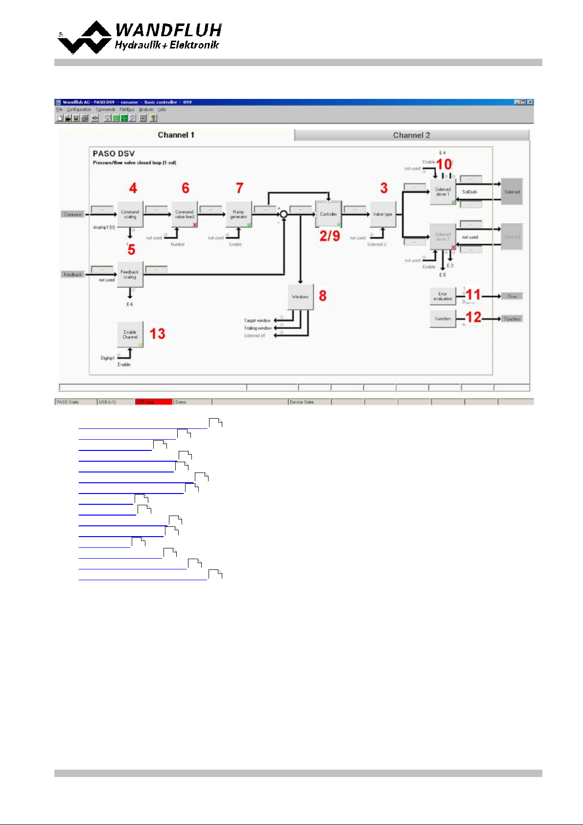
4 Setup Instruction Pressure/flow valve closed loop (1-sol)
................................................................................................................................................................................. 194.1 Introduction
................................................................................................................................................................................. 214.2 Activate PASO Off Line mode
................................................................................................................................................................................. 214.3 Select controller mode
................................................................................................................................................................................. 214.4 Select valve type
................................................................................................................................................................................. 214.5 Scale command signal
................................................................................................................................................................................. 224.6 Scale feedback signal
................................................................................................................................................................................. 224.7 Set command values fixed (optional)
................................................................................................................................................................................. 224.8 Set speed (optional)
................................................................................................................................................................................. 224.9 Set windows
................................................................................................................................................................................. 234.10 Set controller
................................................................................................................................................................................. 234.11 Set solenoid driver 1
................................................................................................................................................................................. 244.12 Set error evaluation (optional)
................................................................................................................................................................................. 244.13 Set function (optional)
................................................................................................................................................................................. 244.14 Set enable channel
................................................................................................................................................................................. 254.15 Save parameters in a file (optional)
................................................................................................................................................................................. 264.16 Activate PASO On Line mode
5 Setup Instruction Pressure control closed loop (2-sol) 27
................................................................................................................................................................................. 275.1 Introduction
................................................................................................................................................................................. 295.2 Activate PASO Off Line mode
................................................................................................................................................................................. 295.3 Select controller mode
................................................................................................................................................................................. 295.4 Select valve type
................................................................................................................................................................................. 295.5 Scale command signal
................................................................................................................................................................................. 305.6 Scale feedback signal
................................................................................................................................................................................. 305.7 Set command values fixed (optional)
................................................................................................................................................................................. 305.8 Set speed (optional)
................................................................................................................................................................................. 305.9 Set windows
................................................................................................................................................................................. 315.10 Set controller
................................................................................................................................................................................. 315.11 Set solenoid driver 1
................................................................................................................................................................................. 325.12 Set solenoid driver 2
................................................................................................................................................................................. 325.13 Set error evaluation (optional)
................................................................................................................................................................................. 325.14 Set function (optional)
19
5
Wandfluh AG
Postfach
CH-3714 Frutigen
Tel: +41 33 672 72 72
Fax: +41 33 672 72 12
Email: sales@wandfluh.com
Internet: www.wandfluh.com
Page 2
Edition 09 13
DSV_StepByStep_d.pdf
Page 3

Step by Step Instruction for Controller Electronics DSV
................................................................................................................................................................................. 325.15 Set enable channel
................................................................................................................................................................................. 335.16 Save parameters in a file (optional)
................................................................................................................................................................................. 345.17 Activate PASO On Line mode
6 Setup Instruction Position closed loop (2-sol) 35
................................................................................................................................................................................. 356.1 Introduction
................................................................................................................................................................................. 376.2 Activate PASO Off Line mode
................................................................................................................................................................................. 376.3 Select controller mode
................................................................................................................................................................................. 376.4 Select valve type
................................................................................................................................................................................. 376.5 Scale command signal
................................................................................................................................................................................. 386.6 Scale feedback signal
................................................................................................................................................................................. 386.7 Set command values fixed (optional)
................................................................................................................................................................................. 386.8 Set speed (optional)
................................................................................................................................................................................. 386.9 Set windows
................................................................................................................................................................................. 396.10 Set controller
................................................................................................................................................................................. 396.11 Set solenoid driver 1
................................................................................................................................................................................. 406.12 Set solenoid driver 2
................................................................................................................................................................................. 406.13 Set error evaluation (optional)
................................................................................................................................................................................. 406.14 Set function (optional)
................................................................................................................................................................................. 406.15 Set enable channel
................................................................................................................................................................................. 416.16 Save parameters in a file (optional)
................................................................................................................................................................................. 426.17 Activate PASO On Line mode
7 Setup Instruction Speed control closed loop (2-sol) 43
................................................................................................................................................................................. 437.1 Introduction
................................................................................................................................................................................. 457.2 Activate PASO Off Line mode
................................................................................................................................................................................. 457.3 Select controller mode
................................................................................................................................................................................. 457.4 Select valve type
................................................................................................................................................................................. 457.5 Scale command signal
................................................................................................................................................................................. 467.6 Scale feedback signal
................................................................................................................................................................................. 467.7 Set command values fixed (optional)
................................................................................................................................................................................. 467.8 Set speed (optional)
................................................................................................................................................................................. 467.9 Set windows
................................................................................................................................................................................. 477.10 Set controller
................................................................................................................................................................................. 477.11 Set solenoid driver 1
................................................................................................................................................................................. 487.12 Set solenoid driver 2
................................................................................................................................................................................. 487.13 Set error evaluation (optional)
................................................................................................................................................................................. 487.14 Set function (optional)
................................................................................................................................................................................. 487.15 Set enable channel
................................................................................................................................................................................. 497.16 Save parameters in a file (optional)
................................................................................................................................................................................. 507.17 Activate PASO On Line mode
8 Setup Instruction 2-point controller (1-sol) 51
................................................................................................................................................................................. 518.1 Introduction
................................................................................................................................................................................. 538.2 Activate PASO Off Line mode
................................................................................................................................................................................. 538.3 Select controller mode
................................................................................................................................................................................. 538.4 Select valve type
................................................................................................................................................................................. 538.5 Select controller mode "2-point controller (1-sol)"
................................................................................................................................................................................. 548.6 Scale feedback signal
................................................................................................................................................................................. 548.7 Set command values fixed (optional)
................................................................................................................................................................................. 548.8 Set speed (optional)
................................................................................................................................................................................. 548.9 Set windows
................................................................................................................................................................................. 558.10 Set controller
................................................................................................................................................................................. 558.11 Set solenoid driver 1
................................................................................................................................................................................. 558.12 Set error evaluation (optional)
................................................................................................................................................................................. 568.13 Set function (optional)
................................................................................................................................................................................. 568.14 Set enable channel
................................................................................................................................................................................. 578.15 Save parameters in a file (optional)
................................................................................................................................................................................. 588.16 Activate PASO On Line mode
9 Setup Instruction 2-point controller (2-sol)
................................................................................................................................................................................. 599.1 Introduction
................................................................................................................................................................................. 619.2 Activate PASO Off Line mode
................................................................................................................................................................................. 619.3 Select controller mode
................................................................................................................................................................................. 619.4 Select valve type
................................................................................................................................................................................. 619.5 Scale command signal
................................................................................................................................................................................. 629.6 Scale feedback signal
................................................................................................................................................................................. 629.7 Set command values fixed (optional)
................................................................................................................................................................................. 629.8 Set speed (optional)
59
Wandfluh AG
Postfach
CH-3714 Frutigen
Tel: +41 33 672 72 72
Fax: +41 33 672 72 12
Email: sales@wandfluh.com
Internet: www.wandfluh.com
Page 3
Edition 09 13
DSV_StepByStep_d.pdf
Page 4

Step by Step Instruction for Controller Electronics DSV
................................................................................................................................................................................. 629.9 Set windows
................................................................................................................................................................................. 639.10 Set controller
................................................................................................................................................................................. 639.11 Set solenoid driver 1
................................................................................................................................................................................. 649.12 Set solenoid driver 2
................................................................................................................................................................................. 649.13 Set error evaluation (optional)
................................................................................................................................................................................. 649.14 Set function (optional)
................................................................................................................................................................................. 649.15 Set enable channel
................................................................................................................................................................................. 659.16 Save parameters in a file (optional)
................................................................................................................................................................................. 669.17 Activate PASO On Line mode
10 Setup Instruction 3-point controller (2-sol) 67
................................................................................................................................................................................. 6710.1 Introduction
................................................................................................................................................................................. 6910.2 Activate PASO Off Line mode
................................................................................................................................................................................. 6910.3 Select controller mode
................................................................................................................................................................................. 6910.4 Select valve type
................................................................................................................................................................................. 6910.5 Scale command signal
................................................................................................................................................................................. 7010.6 Scale feedback signal
................................................................................................................................................................................. 7010.7 Set command values fixed (optional)
................................................................................................................................................................................. 7010.8 Set speed (optional)
................................................................................................................................................................................. 7010.9 Set windows
................................................................................................................................................................................. 7110.10Set controller
................................................................................................................................................................................. 7110.11Set solenoid driver 1
................................................................................................................................................................................. 7210.12Set solenoid driver 2
................................................................................................................................................................................. 7210.13Set error evaluation (optional)
................................................................................................................................................................................. 7210.14Set function (optional)
................................................................................................................................................................................. 7210.15Set enable channel
................................................................................................................................................................................. 7310.16Save parameters in a file (optional)
................................................................................................................................................................................. 7410.17Activate PASO On Line mode
Wandfluh AG
Postfach
CH-3714 Frutigen
Tel: +41 33 672 72 72
Fax: +41 33 672 72 12
Email: sales@wandfluh.com
Internet: www.wandfluh.com
Page 4
Edition 09 13
DSV_StepByStep_d.pdf
Page 5

Step by Step Instruction for Controller Electronics DSV
1
This step by step guide is designed to provide the user with a simple alignment. It contains for any amplifier or
controller type an instruction which describes the required parameters in the correct order.
For a detailed description of the hardware, a product description and a description of all parameters, please refer
to "Operating instructions to Amplifier Electronics DSV" resp. "Operating instructions to Controller Electronics
DSV".
Note: Please read in advance the appropriate operating instruction.
General Information
Wandfluh AG
Postfach
CH-3714 Frutigen
Tel: +41 33 672 72 72
Fax: +41 33 672 72 12
Email: sales@wandfluh.com
Internet: www.wandfluh.com
Page 5
Edition 09 13
DSV_StepByStep_d.pdf
Page 6
Step by Step Instruction for Controller Electronics DSV
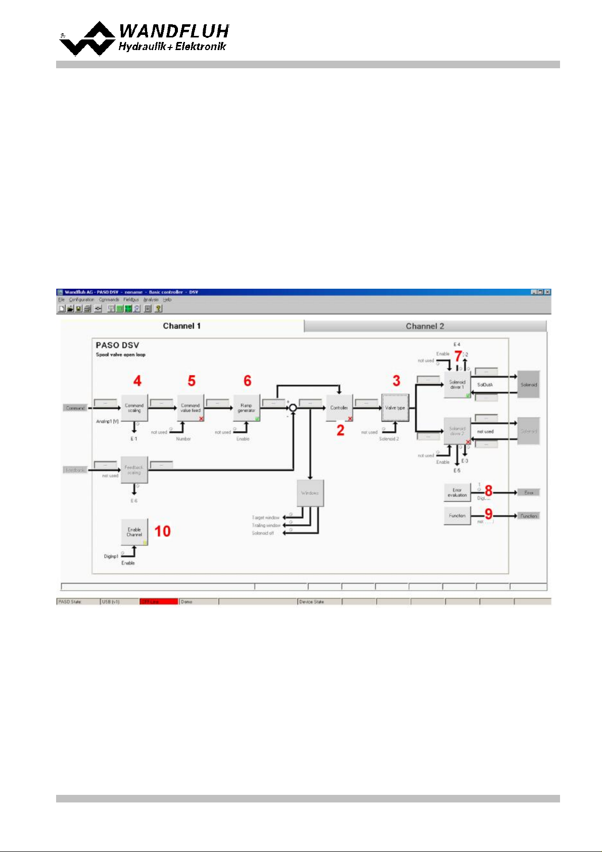
Controller mode:
Spool valve open loop
Command signal:
0 ... 10V at the analog input 1
Mode of operation:
0 ... 10V command value for solenoid A
Valve connection:
3/2-way proportional valve at solenoid A
Enable channel:
external via digital input 1
2
Setup Instruction 1-solenoid valve open loop
2.1 Introduction
This guide shows with an example how to set the DSV Electronics for controlling a 3/2-way proportional valve in
a open loop control (without a feedback signal) for controlling a hydraulic motor with one directions.
Pretended:
The following steps are necessary (steps with the remark "optional" are only necessary if needed):
Wandfluh AG
Postfach
CH-3714 Frutigen
Tel: +41 33 672 72 72
Fax: +41 33 672 72 12
Email: sales@wandfluh.com
Internet: www.wandfluh.com
Page 6
Edition 09 13
DSV_StepByStep_d.pdf
Page 7
1.
Activate PASO Off Line mode
2.
Select controller mode (only with a DSV controller)
3.
Select valve type
4.
Scale command signal
5.
Set command values fixed (optional)
6.
Set ramp generator (optional)
7.
Set solenoid driver 1
8.
Set error evaluation (optional)
9.
Set function (optional)
10.
Set enable channel
11.
Save parameters in a file (optional)
12.
Activate PASO On Line mode
13.
By activating the digital input 1, the channel 1 will be released in the controller mode "Pressure/flow valve
open loop"
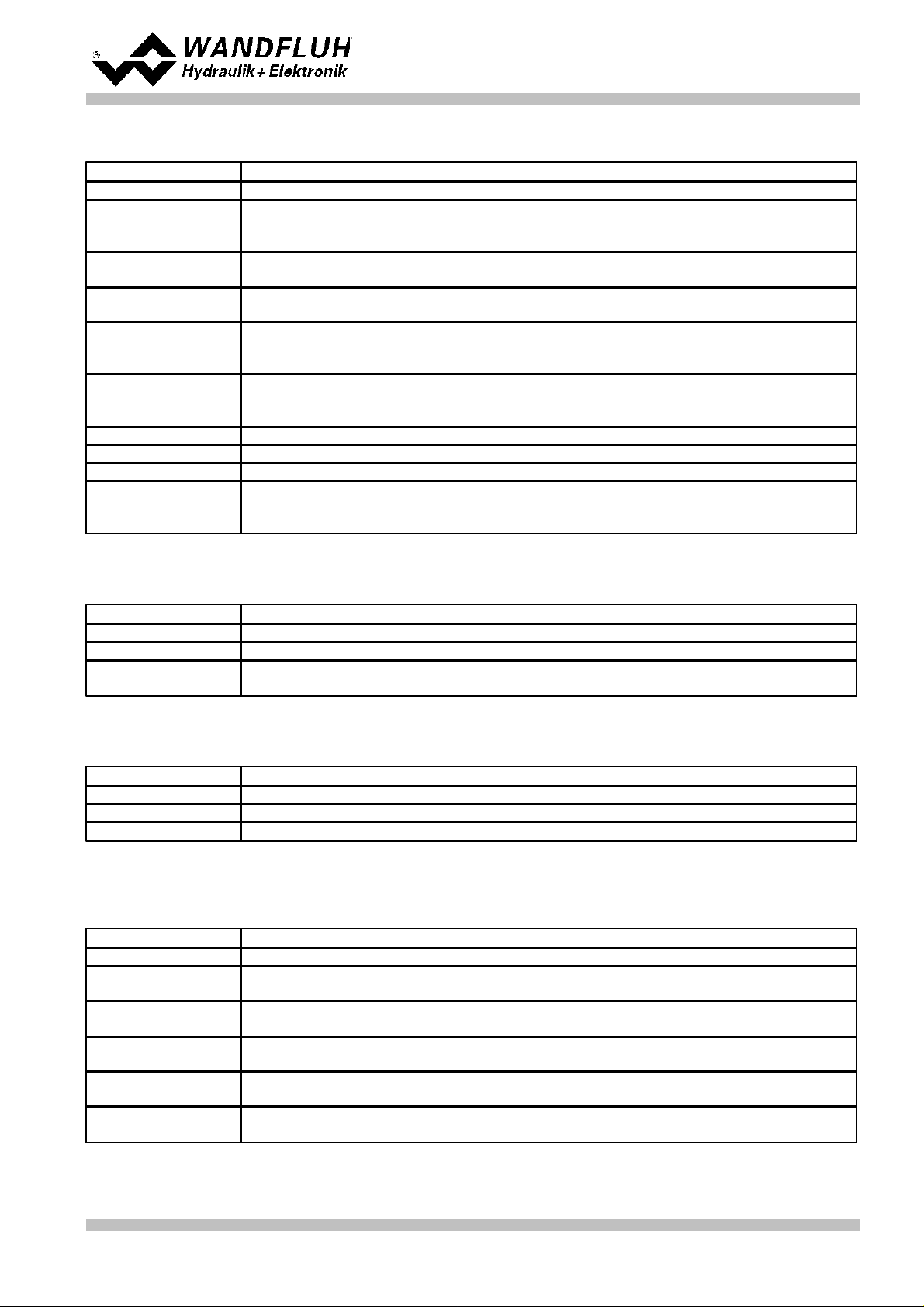
Parameter
Description
Controller mode
Select controller mode "Spool valve open loop"
Parameter
Description
Mode of operation
Select the corresponding mode of operation (in the example "Command unipolar
(1-sol)")
Solenoid type
Select the solenoid type of the connected valve (in the example "Proportional solenoid
with current measurement")
Valve type
Select the valve type of the connected valve (in the example "Standard 2-solenoid")
7
7
7
8
8
8
8
9
9
9
10
11
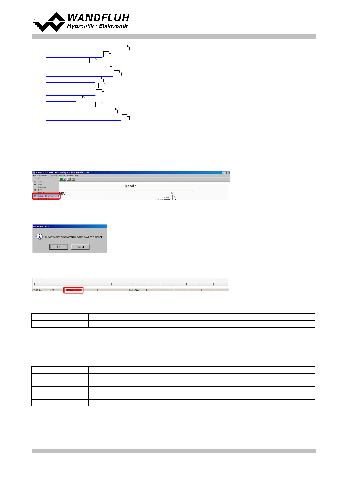
2.2 Activate PASO Off Line mode
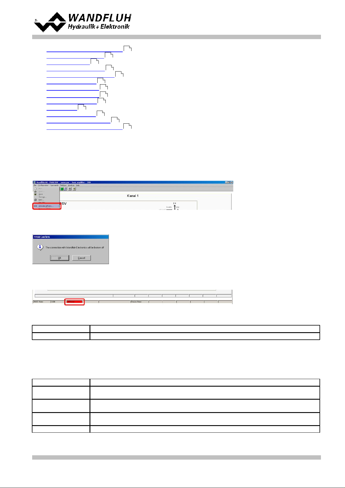
Select "File - Activate Off Line"
Step by Step Instruction for Controller Electronics DSV
Select "OK"
In the status line the message "Off-Line" appears
2.3 Select controller mode (only with a DSVcontroller)
All other parameters in this window will be set later.
2.4 Select valve type
The remaining parameters have no function in this control mode
Wandfluh AG
Postfach
CH-3714 Frutigen
Tel: +41 33 672 72 72
Fax: +41 33 672 72 12
Email: sales@wandfluh.com
Internet: www.wandfluh.com
DSV_StepByStep_d.pdf
Page 7
Edition 09 13
Page 8
2.5 Scale command signal
Parameter
Description
Signal type
Set the signal type from the command signal generator (in the example "Voltage")
Used analog input
If the parameter "Signal type" is set to "Voltage" or "Current", the input where the
command signal generator is connect can be selected here (in the example "AnaInp1
[V]")
Used digital input
If the parameter "Signal type" is set to "Digital", "Frequency" or "PWM", the input where
the command signal generator is connect can be selected here
Cablebreak
detection
If the parameter "Signal type" is set to "Current", "Frequency" or "PWM", a cablebreak
detection of the command signal generator can be activated
Lower cablebreak
limit
If the parameter "Cablebreak detection" is set to "yes", the lower limit of this detection
can be set here
(command value < lower cablebreak limit = cablebreak)
Upper cablebreak
limit
If the parameter "Cablebreak detection" is set to "yes", the upper limit of this detection
can be set here
(command value > upper cablebreak limit = cablebreak)
min interface
Set the minimum command signal level (in the example 0V)
max interface
Set the maximum command signal level (in the example 10V)
Deadband function
Enable the deadband function
Deadband threshold
If the parameter "Deadband function" is set to "on", the threshold for the deadband can
be set here
(command value < deadband threshold => solenoid output = 0)
Parameter
Description
Enable
Enable the fixed command value function
Selection 1
Set the desired digital input for the fixed command value 1
Fixed command
value 1
Set the desired command value for the fixed command value 1. This value becomes the
active command value if the digital from "Selection 1" is activated
Parameter
Description
Enable
Enable the ramp generator function
Ramp positive up
Ramptime for the current increase on solenoid driver 1
Ramp positive down
Ramptime for the current decrease on solenoid driver 1
Parameter
Description
Solenoid output
Select the output, where the solenoid is connected (in the example "SolOutA")
Enable
Selection, if the solenoid output is constantly enabled (selection "on"), constantly
disabled (selection "off") or if it depends on a digital input (selection "external")
Dig. input
If the parameter "Enable" is set to "external", the corresponding digital input can be
selected here
Inversion
If a solenoid with a inverse function is used, this selection should be "yes", otherwise
"no"
Solenoid always
active
In this control mode, this parameter must always be set to "no"
Cablebreak
detection
If the cablebreak detection for the solenoid output is desired, this selection should be
"yes", otherwise "no"
Step by Step Instruction for Controller Electronics DSV
2.6 Set command values fixed (optional)
2.7 Set ramp generator (optional)
2.8 Set solenoid driver 1
Wandfluh AG
Postfach
CH-3714 Frutigen
Tel: +41 33 672 72 72
Fax: +41 33 672 72 12
Email: sales@wandfluh.com
Internet: www.wandfluh.com
Page 8
Edition 09 13
DSV_StepByStep_d.pdf
Page 9
Step by Step Instruction for Controller Electronics DSV
Characteristic
optimisation
If the characteristic optimisation is desired, this selection should be "yes", otherwise
"no".
(the settings for the characteristic optimisation is made in the Tab-window
"Characteristic optimisation")
Imin
Set the desired minimum current for solenoid A (correspond to the current at 0%
command signal)
Imax
Set the desired maximum current for solenoid A (correspond to the current at 100%
command signal)
Dither function
The dither function should be activated (Selection "on")
Dither frequency
Set the desired dither frequency value
Dither level
Set the desired dither level value
Parameter
Description
Selection
Here one can choose what error should activate the selected digital output
Dig. output
As soon as one of the selected error occurs, the selected digital output will be activated
Error action
With error "Cablebreak command signal" and "Cablebreak feedback signal", the desired
error action can be set. The default setting is "Solenoid 1 + 2 off"
Parameter
Description
Selection
Here one can choose what function should activate the selected digital output
Dig. output
As soon as one of the selected functions occurs, the selected digital output will be
activated
Parameter
Description
Enable
Selection, if the channel is constantly enabled (selection "on"), constantly disabled
(selection "off") of if it depends on a digital input (selection "external")
Dig. input
If the parameter "Enable" is set to *external", the corresponding digital input can be
selected here (in the example "DigInp1")
The remaining parameters have no function in this control mode
2.9 Set error evaluation (optional)
2.10 Set function (optional)
2.11 Set enable channel
Wandfluh AG
Postfach
CH-3714 Frutigen
Tel: +41 33 672 72 72
Fax: +41 33 672 72 12
Email: sales@wandfluh.com
Internet: www.wandfluh.com
Page 9
Edition 09 13
DSV_StepByStep_d.pdf
Page 10

Step by Step Instruction for Controller Electronics DSV
2.12 Save parameters in a file (optional)
Select "File - Save as ..."
Enter the directory and file name, afterwards select "OK"
If required, enter the corresponding values to "Operator" and "Remarks", afterwards select "OK"
In the header line the corresponding file name appears
Wandfluh AG
Postfach
CH-3714 Frutigen
Tel: +41 33 672 72 72
Fax: +41 33 672 72 12
Email: sales@wandfluh.com
Internet: www.wandfluh.com
Page 10
Edition 09 13
DSV_StepByStep_d.pdf
Page 11
Step by Step Instruction for Controller Electronics DSV
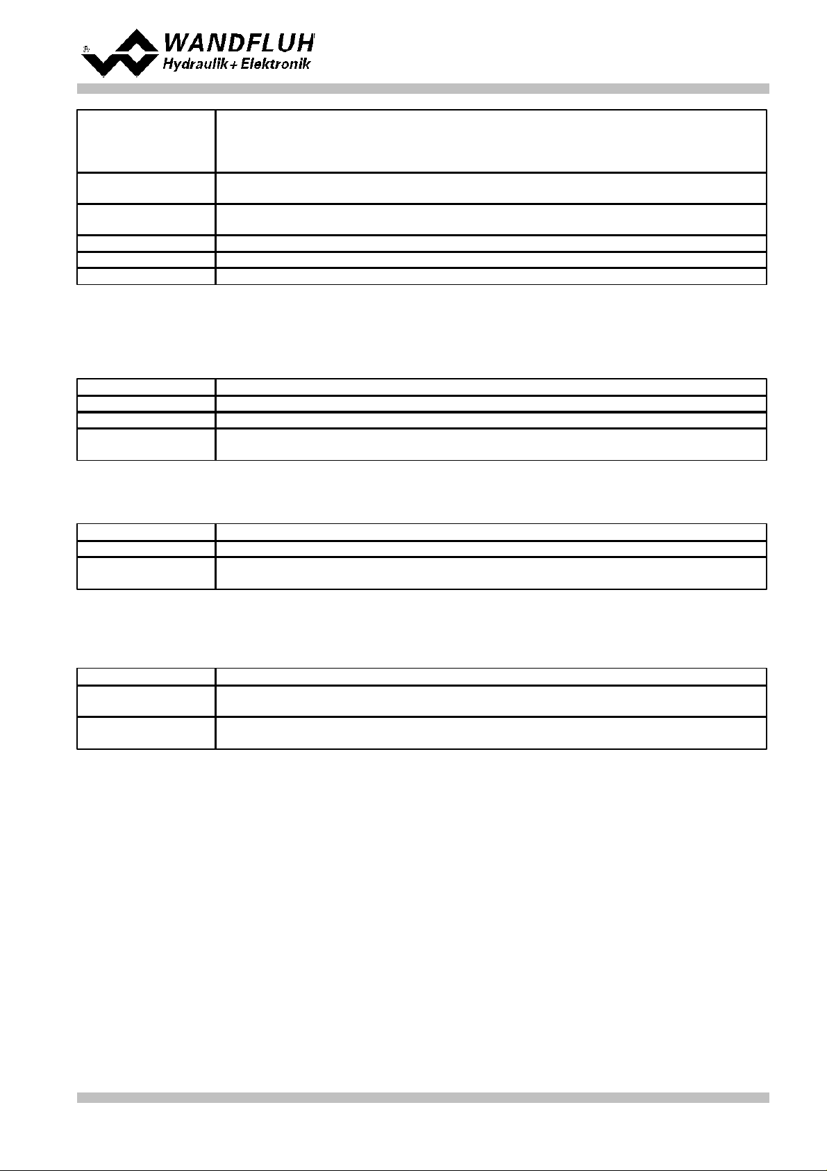
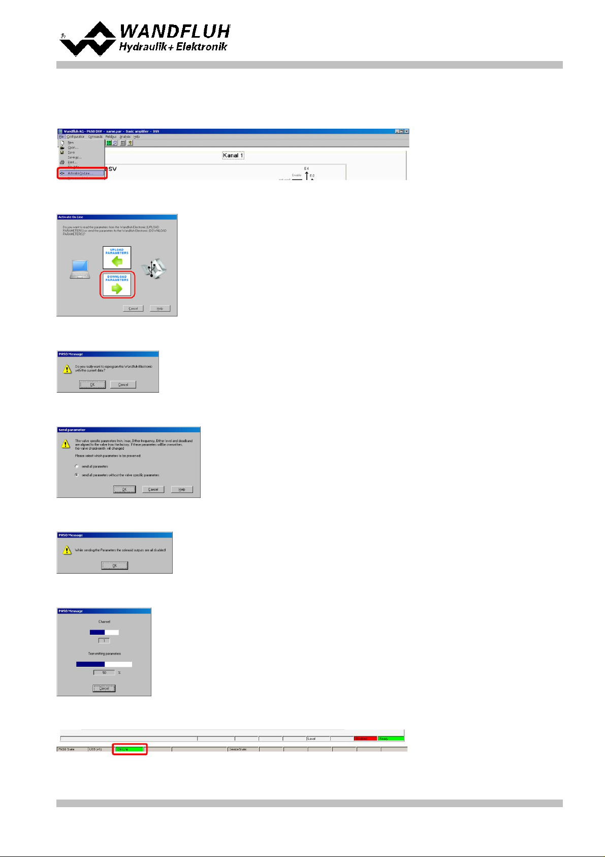
2.13 Activate PASO On Line mode
Select "File - Activate On Line"
Select "Program the Wandfluh-Electronic with the new actual data?"
Select "OK"
Select "send all parameters without the valve specific parameters"
Select "OK"
Wait, until all parameters are sent to the DSV Electronics
In the status line the message "On-Line" appears
Wandfluh AG
Postfach
CH-3714 Frutigen
Tel: +41 33 672 72 72
Fax: +41 33 672 72 12
Email: sales@wandfluh.com
Internet: www.wandfluh.com
Page 11
Edition 09 13
DSV_StepByStep_d.pdf
Page 12
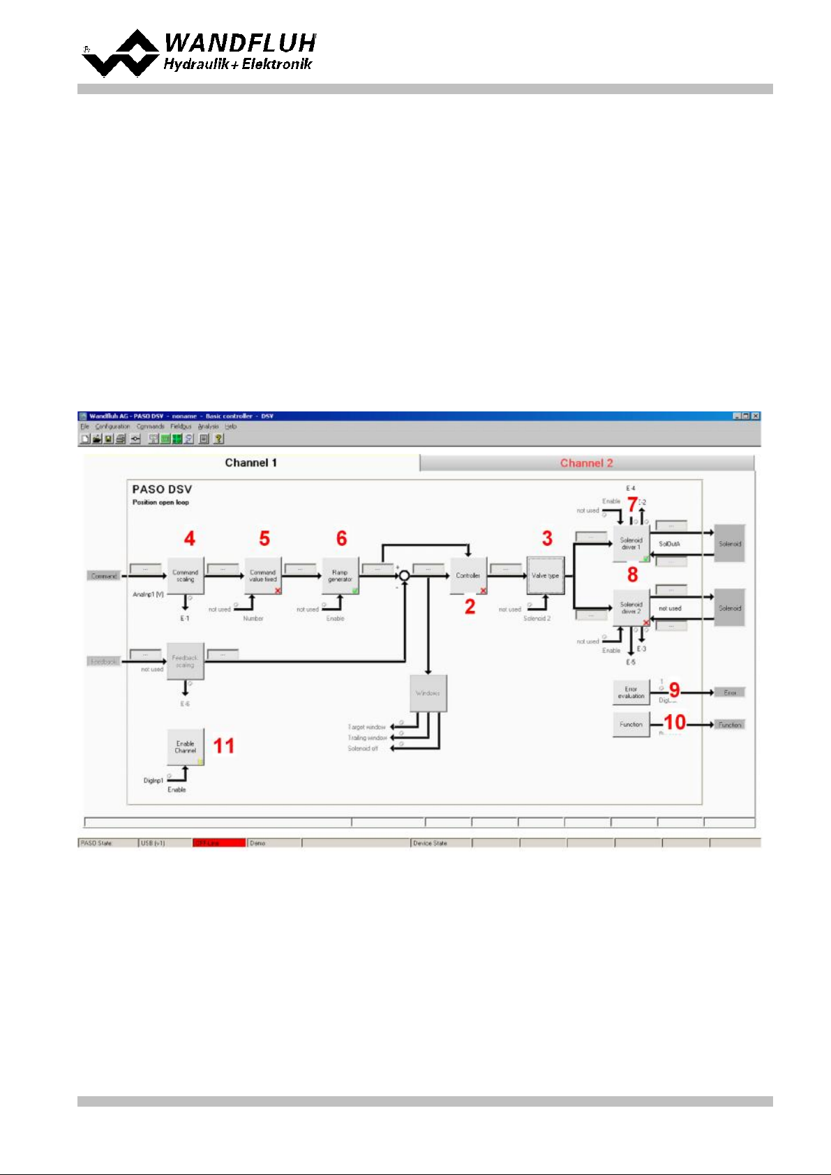
Step by Step Instruction for Controller Electronics DSV
Controller mode:
Position open loop
Command signal:
0 ... 10V at the analog input 1
Mode of operation:
0 ... 5V command value for solenoid B, 5 ... 10V command value for solenoid A
Valve connection:
4/3-way proportional valve, solenoid A = direction right, solenoid B = direction left
Enable channel:
external via digital input 1
3
Setup Instruction 2-solenoid valve open loop
3.1 Introduction
This guide shows with an example how to set the DSV Electronics for controlling a 4/3-way proportional valve in
a open loop control (without a feedback signal) for controlling a hydraulic motor with two directions.
Pretended:
The following steps are necessary (steps with the remark "optional" are only necessary if needed):
Wandfluh AG
Postfach
CH-3714 Frutigen
Tel: +41 33 672 72 72
Fax: +41 33 672 72 12
Email: sales@wandfluh.com
Internet: www.wandfluh.com
Page 12
Edition 09 13
DSV_StepByStep_d.pdf
Page 13
1.
Activate PASO Off Line mode
2.
Select controller mode (only with a DSV controller)
3.
Select valve type
4.
Scale command signal
5.
Set command values fixed (optional)
6.
Set ramp generator (optional)
7.
Set solenoid driver 1
8.
Set solenoid driver 2
9.
Set error evaluation (optional)
10.
Set function (optional)
11.
Set enable channel
12.
Save parameters in a file (optional)
13.
Activate PASO On Line mode
14.
By activating the digital input 1, the channel 1 will be released in the controller mode "Position open loop"
Parameter
Description
Controller mode
Select controller mode "Position open loop"
Parameter
Description
Mode of operation
Select the corresponding mode of operation (in the example "Command unipolar
(2-sol)")
Solenoid B
If the parameter "Mode of operation" is set to "Command unipolar (2-sol with DigInp)",
the corresponding digital input can be selected here
Solenoid type
Select the solenoid type of the connected valve (in the example "Proportional solenoid
with current measurement")
Valve type
Select the valve type of the connected valve (in the example "Standard 2-solenoid")
13
13
13
14
14
14
14
15
15
16
16
17
18
3.2 Activate PASO Off Line mode
Select "File - Activate Off Line"
Step by Step Instruction for Controller Electronics DSV
Select "OK"
In the status line the message "Off-Line" appears
3.3 Select controller mode (only with a DSVcontroller)
All other parameters in this window will be set later.
3.4 Select valve type
Wandfluh AG
Postfach
CH-3714 Frutigen
Tel: +41 33 672 72 72
Fax: +41 33 672 72 12
Email: sales@wandfluh.com
Internet: www.wandfluh.com
Page 13
Edition 09 13
DSV_StepByStep_d.pdf
Page 14
3.5 Scale command signal
Parameter
Description
Signal type
Set the signal type from the command signal generator (in the example "Voltage")
Used analog input
If the parameter "Signal type" is set to "Voltage" or "Current", the input where the
command signal generator is connect can be selected here (in the example "AnaInp1
[V]")
Used digital input
If the parameter "Signal type" is set to "Digital", "Frequency" or "PWM", the input where
the command signal generator is connect can be selected here
Cablebreak
detection
If the parameter "Signal type" is set to "Current", "Frequency" or "PWM", a cablebreak
detection of the command signal generator can be activated
Lower cablebreak
limit
If the parameter "Cablebreak detection" is set to "yes", the lower limit of this detection
can be set here
(command value < lower cablebreak limit = cablebreak)
Upper cablebreak
limit
If the parameter "Cablebreak detection" is set to "yes", the upper limit of this detection
can be set here
(command value > upper cablebreak limit = cablebreak)
min interface
Set the minimum command signal level (in the example 0V)
max interface
Set the maximum command signal level (in the example 10V)
Deadband function
Enable the deadband function
Deadband threshold
If the parameter "Deadband function" is set to "on", the threshold for the deadband can
be set here
(command value < deadband threshold => solenoid output = 0)
Parameter
Description
Enable
Enable the fixed command value function
Selection 1
Set the desired digital input for the fixed command value 1
Fixed command
value 1
Set the desired command value for the fixed command value 1. This value becomes the
active command value if the digital from "Selection 1" is activated
Parameter
Description
Enable
Enable the ramp generator function
Ramp positive up
Ramptime for the current increase on solenoid driver 1
Ramp positive down
Ramptime for the current decrease on solenoid driver 1
Ramp negative up
Ramptime for the current increase on solenoid driver 2
Ramp negative
down
Ramptime for the current decrease on solenoid driver 2
Parameter
Description
Solenoid output
Select the output, where the solenoid for right turning is connected (in the example
"SolOutA")
Enable
Selection, if the solenoid output is constantly enabled (selection "on"), constantly
disabled (selection "off") or if it depends on a digital input (selection "external")
Dig. input
If the parameter "Enable" is set to "external", the corresponding digital input can be
selected here
Inversion
If a solenoid with a inverse function is used, this selection should be "yes", otherwise
"no"
Step by Step Instruction for Controller Electronics DSV
3.6 Set command values fixed (optional)
3.7 Set ramp generator (optional)
3.8 Set solenoid driver 1
Wandfluh AG
Postfach
CH-3714 Frutigen
Tel: +41 33 672 72 72
Fax: +41 33 672 72 12
Email: sales@wandfluh.com
Internet: www.wandfluh.com
Page 14
Edition 09 13
DSV_StepByStep_d.pdf
Page 15
Step by Step Instruction for Controller Electronics DSV
Solenoid always
active
In this control mode, this parameter must always be set to "no"
Cablebreak
detection
If the cablebreak detection for the solenoid output is desired, this selection should be
"yes", otherwise "no"
Characteristic
optimisation
If the characteristic optimisation is desired, this selection should be "yes", otherwise
"no".
(the settings for the characteristic optimisation is made in the Tab-window
"Characteristic optimisation")
Imin
Set the desired minimum current for solenoid A (correspond to the current at 0%
command signal)
Imax
Set the desired maximum current for solenoid A (correspond to the current at 100%
command signal)
Dither function
The dither function should be activated (Selection "on")
Dither frequency
Set the desired dither frequency value
Dither level
Set the desired dither level value
Parameter
Description
Solenoid output
Select the output, where the solenoid for left turning is connected (in the example
"SolOutB")
Enable
Selection, if the solenoid output is constantly enabled (selection "on"), constantly
disabled (selection "off") or if it depends on a digital input (selection "external")
Dig. input
If the parameter "Enable" is set to "external", the corresponding digital input can be
selected here
Inversion
If a solenoid with a inverse function is used, this selection should be "yes", otherwise
"no"
Solenoid always
active
In this control mode, this parameter must always be set to "no"
Cablebreak
detection
If the cablebreak detection for the solenoid output is desired, this selection should be
"yes", otherwise "no"
Characteristic
optimisation
If the characteristic optimisation is desired, this selection should be "yes", otherwise
"no".
(the settings for the characteristic optimisation is made in the Tab-window
"Characteristic optimisation")
Imin
Set the desired minimum current for solenoid B (correspond to the current at -0.1%
command signal)
Imax
Set the desired maximum current for solenoid B (correspond to the current at -100%
command signal)
Dither function
The dither function should be activated (Selection "on")
Dither frequency
Set the desired dither frequency value
Dither level
Set the desired dither level value
Parameter
Description
Selection
Here one can choose what error should activate the selected digital output
Dig. output
As soon as one of the selected error occurs, the selected digital output will be activated
Error action
With error "Cablebreak command signal" and "Cablebreak feedback signal", the desired
error action can be set. The default setting is "Solenoid 1 + 2 off"
The remaining parameters have no function in this control mode
3.9 Set solenoid driver 2
The remaining parameters have no function in this control mode
3.10 Set error evaluation (optional)
Wandfluh AG
Postfach
CH-3714 Frutigen
Tel: +41 33 672 72 72
Fax: +41 33 672 72 12
Email: sales@wandfluh.com
Internet: www.wandfluh.com
Page 15
Edition 09 13
DSV_StepByStep_d.pdf
Page 16
3.11 Set function (optional)
Parameter
Description
Selection
Here one can choose what function should activate the selected digital output
Dig. output
As soon as one of the selected functions occurs, the selected digital output will be
activated
Parameter
Description
Enable
Selection, if the channel is constantly enabled (selection "on"), constantly disabled
(selection "off") of if it depends on a digital input (selection "external")
Dig. input
If the parameter "Enable" is set to *external", the corresponding digital input can be
selected here (in the example "DigInp1")
3.12 Set enable channel
Step by Step Instruction for Controller Electronics DSV
Wandfluh AG
Postfach
CH-3714 Frutigen
Tel: +41 33 672 72 72
Fax: +41 33 672 72 12
Email: sales@wandfluh.com
Internet: www.wandfluh.com
Page 16
Edition 09 13
DSV_StepByStep_d.pdf
Page 17

Step by Step Instruction for Controller Electronics DSV
3.13 Save parameters in a file (optional)
Select "File - Save as ..."
Enter the directory and file name, afterwards select "OK"
If required, enter the corresponding values to "Operator" and "Remarks", afterwards select "OK"
In the header line the corresponding file name appears
Wandfluh AG
Postfach
CH-3714 Frutigen
Tel: +41 33 672 72 72
Fax: +41 33 672 72 12
Email: sales@wandfluh.com
Internet: www.wandfluh.com
Page 17
Edition 09 13
DSV_StepByStep_d.pdf
Page 18

Step by Step Instruction for Controller Electronics DSV
3.14 Activate PASO On Line mode
Select "File - Activate On Line"
Select "Program the Wandfluh-Electronic with the new actual data?"
Select "OK"
Select "send all parameters without the valve specific parameters"
Select "OK"
Wait, until all parameters are sent to the DSV Electronics
In the status line the message "On-Line" appears
Wandfluh AG
Postfach
CH-3714 Frutigen
Tel: +41 33 672 72 72
Fax: +41 33 672 72 12
Email: sales@wandfluh.com
Internet: www.wandfluh.com
Page 18
Edition 09 13
DSV_StepByStep_d.pdf
Page 19
Step by Step Instruction for Controller Electronics DSV
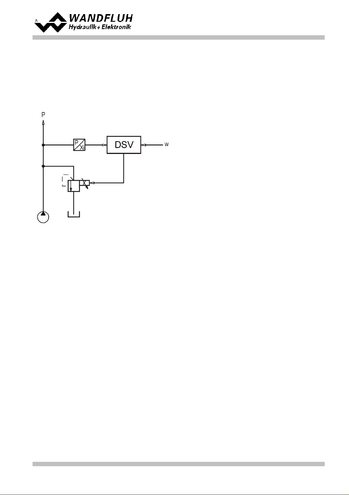
Controller mode:
Pressure/flow valve closed loop (1-sol)
Command signal:
0 ... 20mA on analog input 2
Feedback signal:
0 ... 20mA on analog input 3
max. working
pressure:
0 ... 200bar
desired working
pressure:
10 ... 190bar
Valve connection:
Proportional pressure relief valve on solenoid A
Enable channel:
external via digital input 1
4
Setup Instruction Pressure/flow valve closed loop (1-sol)
4.1 Introduction
This guide shows with an example how to set channel 1 of the DSV Electronics as a pressure controller (1
solenoid)
Pretended:
Wandfluh AG
Postfach
CH-3714 Frutigen
Tel: +41 33 672 72 72
Fax: +41 33 672 72 12
Email: sales@wandfluh.com
Internet: www.wandfluh.com
Page 19
Edition 09 13
DSV_StepByStep_d.pdf
Page 20
Step by Step Instruction for Controller Electronics DSV
1.
Activate PASO Off Line mode
2.
Select controller mode
3.
Select valve type
4.
Scale command signal
5.
Scale feedback signal
6.
Set command values fixed (optional)
7.
Set command generator
8.
Set windows
9.
Set controller
10.
Set solenoid driver 1
11.
Set error evaluation (optional)
12.
Set function (optional)
13.
Set enable channel
14.
Save parameters in a file (optional)
15.
Activate PASO On Line mode
16.
By activating the digital input 1, the channel 1 will be released in the controller mode "Pressure/flow valve
closed loop (1-sol)"
The following steps are necessary (steps with the remark "optional" are only necessary if needed):
21
21
21
21
22
22
22
22
23
23
24
24
24
25
26
Wandfluh AG
Postfach
CH-3714 Frutigen
Tel: +41 33 672 72 72
Fax: +41 33 672 72 12
Email: sales@wandfluh.com
Internet: www.wandfluh.com
DSV_StepByStep_d.pdf
Page 20
Edition 09 13
Page 21

4.2 Activate PASO Off Line mode
Parameter
Description
Controller mode
Select controller mode "Pressure/flow valve closed loop (1-sol)"
Displayed unit
Select the desired unit (in the example "bar").
Parameter
Description
Solenoid type
Select the solenoid type of the connected valve (in the example "Proportional solenoid
with current measurement")
Valve type
Select the valve type of the connected valve (in the example "Standard 2-solenoid")
Parameter
Description
Signal type
Set the signal type from the command signal generator (in the example "Current")
Used analog input
If the parameter "Signal type" is set to "Voltage" or "Current", the input where the
command signal generator is connect can be selected here (in the example "AnaInp1
[mA]")
Used digital input
If the parameter "Signal type" is set to "Digital", "Frequency" or "PWM", the input where
the command signal generator is connect can be selected here
Cablebreak
detection
If the parameter "Signal type" is set to "Current", "Frequency" or "PWM", a cablebreak
detection of the command signal generator can be activated
Lower cablebreak
limit
If the parameter "Cablebreak detection" is set to "yes", the lower limit of this detection
can be set here
(command value < lower cablebreak limit = cablebreak)
Upper cablebreak
limit
If the parameter "Cablebreak detection" is set to "yes", the upper limit of this detection
can be set here
(command value > upper cablebreak limit = cablebreak)
Select "File - Activate Off Line"
Select "OK"
In the status line the message "Off-Line" appears
Step by Step Instruction for Controller Electronics DSV
4.3 Select controller mode
All other parameters in this window will be set later.
4.4 Select valve type
The remaining parameters have no function in this control mode
4.5 Scale command signal
Wandfluh AG
Postfach
CH-3714 Frutigen
Tel: +41 33 672 72 72
Fax: +41 33 672 72 12
Email: sales@wandfluh.com
Internet: www.wandfluh.com
Page 21
Edition 09 13
DSV_StepByStep_d.pdf
Page 22
Step by Step Instruction for Controller Electronics DSV
min interface
Set the minimum command signal level (in the example 0mA)
max interface
Set the maximum command signal level (in the example 20mA)
min reference
Set the minimum desired pressure (correspond to the pressure at "min interface", in the
example 10bar)
max reference
Set the maximum desired pressure (correspond to the pressure at "max interface", in
the example 190bar)
Parameter
Description
Signal type
Set the signal type from the feedback signal generator (in the example "Current")
Used analog input
If the parameter "Signal type" is set to "Voltage" or "Current", the input where the
feedback signal generator is connect can be selected here (in the example "AnaInp2
[mA]")
Used digital input
If the parameter "Signal type" is set to "Digital", "Frequency" or "PWM", the input where
the feedback signal generator is connect can be selected here
Cablebreak
detection
If the parameter "Signal type" is set to "Current", "Frequency" or "PWM", a cablebreak
detection of the feedback signal generator can be activated
Lower cablebreak
limit
If the parameter "Cablebreak detection" is set to "yes", the lower limit of this detection
can be set here
(feedback value < lower cablebreak limit = cablebreak)
Upper cablebreak
limit
If the parameter "Cablebreak detection" is set to "yes", the upper limit of this detection
can be set here
(feedback value > upper cablebreak limit = cablebreak)
min interface
Set the minimum feedback signal level
(correspond to the feedback signal level at "min reference", in the example 0mA)
max interface
Set the maximum feedback signal level
(correspond to the feedback signal level at "max reference", in the example 20mA)
min reference
Set the minimum possible pressure (in the example 0bar)
max reference
Set the maximum possible pressure (in the example 200bar)
Parameter
Description
Enable
Enable the fixed command value function
Selection 1
Set the desired digital input for the fixed command value 1
Fixed command
value 1
Set the desired command value for the fixed command value 1. This value becomes the
active command value if the digital from "Selection 1" is activated
Parameter
Description
Speed +
This will set the pressure rise speed of the system
(pressure rise = positive control deviation => command > feedback)
Speed -
This will set the pressure reducing speed of the system
(pressure reducing = negative control deviation => command < feedback)
Parameter
Description
Target window type
Switch on/off the target window function
Target window threshold
Defines the target window range
(control deviation < target window threshold = target window reached)
Target window delay time
Delay time when falling below and exceeding the target window threshold
The remaining parameters have no function in this control mode
4.6 Scale feedback signal
4.7 Set command values fixed (optional)
4.8 Set speed (optional)
4.9 Set windows
Wandfluh AG
Postfach
CH-3714 Frutigen
Tel: +41 33 672 72 72
Fax: +41 33 672 72 12
Email: sales@wandfluh.com
Internet: www.wandfluh.com
Page 22
Edition 09 13
DSV_StepByStep_d.pdf
Page 23

Step by Step Instruction for Controller Electronics DSV
Trailing window type
Switch on/off the trailing window function
ATTENTION: With "on with error", the solenoid outputs will be disabled as
soon as the trailing window is active!
Trailing window threshold
Defines the trailing window range
(control deviation < trailing window threshold = trailing window reached)
Trailing window delay time
Delay time when falling below and exceeding the trailing window threshold
Solenoid-Off window type
Switch on/off the Solenoid-Off window function
Solenoid-Off window
threshold
Defines the Solenoid-Off window range
(control deviation < Solenoid-Off window threshold = solenoid are blocked)
Solenoid-Off window delay
time
Delay time when falling below and exceeding the Solenoid-Off window threshold
Parameter
Description
Command feed
forward
The command value is multiplied with this factor and added to the correcting variable of
the controller. If this factor is 0, no command value proportion is added to the
correcting variable. Ideally, this value is set so that the deviation in the open loop is as
small as possible. The deviation will not have the same size over the whole range.
Thus, the smallest possible deviation can be set in the area where one will be mainly
operate.
Velocity feed forward
In this control mode, this parameter must be set to 0
Parameter
Description
Solenoid output
Select the output, where the solenoid for the loading valve is connected (in the example
"SolOutA")
Enable
Selection, if the solenoid output is constantly enabled (selection "on"), constantly
disabled (selection "off") or if it depends on a digital input (selection "external")
Dig. input
If the parameter "Enable" is set to "external", the corresponding digital input can be
selected here
Inversion
If a solenoid with a inverse function is used, this selection should be "yes", otherwise
"no"
Solenoid always
active
In this control mode, this parameter must always be set to "no"
Cablebreak
detection
If the cablebreak detection for the solenoid output is desired, this selection should be
"yes", otherwise "no"
Characteristic
optimisation
If the characteristic optimisation is desired, this selection should be "yes", otherwise
"no".
(the settings for the characteristic optimisation is made in the Tab-window
"Characteristic optimisation")
Imin
Set the desired minimum current for solenoid A. The Imin should set in the way that with
this value the desired minimum pressure will be reached
Imax
Set the desired maximum current for solenoid A.
The Imax should be approx. the maximal desired pressure +5%
Dither function
The dither function should be activated (Selection "on")
Dither frequency
Set the desired dither frequency value
Dither level
Set the desired dither level value
In this control mode, the "Solenoid-Off" window must be set to "off".
4.10 Set controller
General
PID-controller
Using the parameters of the PID controller the control behavior can be set. The parameter "I window outside"
should meet the highest deviation plus approx. about 10 bar
4.11 Set solenoid driver 1
Wandfluh AG
Postfach
CH-3714 Frutigen
Tel: +41 33 672 72 72
Fax: +41 33 672 72 12
Email: sales@wandfluh.com
Internet: www.wandfluh.com
Page 23
Edition 09 13
DSV_StepByStep_d.pdf
Page 24
Step by Step Instruction for Controller Electronics DSV
Parameter
Description
Selection
Here one can choose what error should activate the selected digital output
Dig. output
As soon as one of the selected error occurs, the selected digital output will be activated
Error action
With error "Cablebreak command signal" and "Cablebreak feedback signal", the desired
error action can be set. The default setting is "Solenoid 1 + 2 off"
Parameter
Description
Selection
Here one can choose what function should activate the selected digital output
Dig. output
As soon as one of the selected functions occurs, the selected digital output will be
activated
Parameter
Description
Enable
Selection, if the channel is constantly enabled (selection "on"), constantly disabled
(selection "off") of if it depends on a digital input (selection "external")
Dig. input
If the parameter "Enable" is set to *external", the corresponding digital input can be
selected here (in the example "DigInp1")
The remaining parameters have no function in this control mode
4.12 Set error evaluation (optional)
4.13 Set function (optional)
4.14 Set enable channel
Wandfluh AG
Postfach
CH-3714 Frutigen
Tel: +41 33 672 72 72
Fax: +41 33 672 72 12
Email: sales@wandfluh.com
Internet: www.wandfluh.com
Page 24
Edition 09 13
DSV_StepByStep_d.pdf
Page 25

Step by Step Instruction for Controller Electronics DSV
4.15 Save parameters in a file (optional)
Select "File - Save as ..."
Enter the directory and file name, afterwards select "OK"
If required, enter the corresponding values to "Operator" and "Remarks", afterwards select "OK"
In the header line the corresponding file name appears
Wandfluh AG
Postfach
CH-3714 Frutigen
Tel: +41 33 672 72 72
Fax: +41 33 672 72 12
Email: sales@wandfluh.com
Internet: www.wandfluh.com
Page 25
Edition 09 13
DSV_StepByStep_d.pdf
Page 26

Step by Step Instruction for Controller Electronics DSV
4.16 Activate PASO On Line mode
Select "File - Activate On Line"
Select "Program the Wandfluh-Electronic with the new actual data?"
Select "OK"
Select "send all parameters without the valve specific parameters"
Select "OK"
Wait, until all parameters are sent to the DSV Electronics
In the status line the message "On-Line" appears
Wandfluh AG
Postfach
CH-3714 Frutigen
Tel: +41 33 672 72 72
Fax: +41 33 672 72 12
Email: sales@wandfluh.com
Internet: www.wandfluh.com
Page 26
Edition 09 13
DSV_StepByStep_d.pdf
Page 27

Step by Step Instruction for Controller Electronics DSV
Controller mode:
Pressure control closed loop (2-sol)
Command signal:
0 ... 20mA on analog input 2
Feedback signal:
0 ... 20mA on analog input 3
max. working
pressure:
0 ... 300bar
desired working
pressure:
20 ... 250bar
Valve connection:
Proportional throttle valve on solenoid A (loading valve), proportional throttle valve on
solenoid B (unloading valve)
Enable channel:
external via digital input 1
5
Setup Instruction Pressure control closed loop (2-sol)
5.1 Introduction
This guide shows with an example how to set channel 1 of the DSV Electronics as a pressure controller (2
solenoid)
Pretended:
Wandfluh AG
Postfach
CH-3714 Frutigen
Tel: +41 33 672 72 72
Fax: +41 33 672 72 12
Email: sales@wandfluh.com
Internet: www.wandfluh.com
Page 27
Edition 09 13
DSV_StepByStep_d.pdf
Page 28

Step by Step Instruction for Controller Electronics DSV
1.
Activate PASO Off Line mode
2.
Select controller mode
3.
Select valve type
4.
Scale command signal
5.
Scale feedback signal
6.
Set command values fixed (optional)
7.
Set command generator
8.
Set windows
9.
Set controller
10.
Set solenoid driver 1
11.
Set solenoid driver 2
12.
Set error evaluation (optional)
13.
Set function (optional)
14.
Set enable channel
15.
Save parameters in a file (optional)
16.
Activate PASO On Line mode
17.
By activating the digital input 1, the channel 1 will be released in the controller mode "Pressure control
closed loop (2-sol)"
The following steps are necessary (steps with the remark "optional" are only necessary if needed):
29
29
29
29
30
30
30
30
31
31
32
32
32
32
33
34
Wandfluh AG
Postfach
CH-3714 Frutigen
Tel: +41 33 672 72 72
Fax: +41 33 672 72 12
Email: sales@wandfluh.com
Internet: www.wandfluh.com
DSV_StepByStep_d.pdf
Page 28
Edition 09 13
Page 29

5.2 Activate PASO Off Line mode
Parameter
Description
Controller mode
Select controller mode "Pressure control closed loop (2-sol)"
Displayed unit
Select the desired unit (in the example "bar").
Parameter
Description
Solenoid type
Select the solenoid type of the connected valve (in the example "Proportional solenoid
with current measurement")
Valve type
Select the valve type of the connected valve (in the example "Standard 2-solenoid")
Parameter
Description
Signal type
Set the signal type from the command signal generator (in the example "Current")
Used analog input
If the parameter "Signal type" is set to "Voltage" or "Current", the input where the
command signal generator is connect can be selected here (in the example "AnaInp1
[mA]")
Used digital input
If the parameter "Signal type" is set to "Digital", "Frequency" or "PWM", the input where
the command signal generator is connect can be selected here
Cablebreak
detection
If the parameter "Signal type" is set to "Current", "Frequency" or "PWM", a cablebreak
detection of the command signal generator can be activated
Lower cablebreak
limit
If the parameter "Cablebreak detection" is set to "yes", the lower limit of this detection
can be set here
(command value < lower cablebreak limit = cablebreak)
Upper cablebreak
limit
If the parameter "Cablebreak detection" is set to "yes", the upper limit of this detection
can be set here
(command value > upper cablebreak limit = cablebreak)
Select "File - Activate Off Line"
Select "OK"
In the status line the message "Off-Line" appears
Step by Step Instruction for Controller Electronics DSV
5.3 Select controller mode
All other parameters in this window will be set later.
5.4 Select valve type
The remaining parameters have no function in this control mode
5.5 Scale command signal
Wandfluh AG
Postfach
CH-3714 Frutigen
Tel: +41 33 672 72 72
Fax: +41 33 672 72 12
Email: sales@wandfluh.com
Internet: www.wandfluh.com
Page 29
Edition 09 13
DSV_StepByStep_d.pdf
Page 30

Step by Step Instruction for Controller Electronics DSV
min interface
Set the minimum command signal level (in the example 0mA)
max interface
Set the maximum command signal level (in the example 20mA)
min reference
Set the minimum desired pressure (correspond to the pressure at "min interface", in the
example 20bar)
max reference
Set the maximum desired pressure (correspond to the pressure at "max interface", in
the example 250bar)
Parameter
Description
Signal type
Set the signal type from the feedback signal generator (in the example "Current")
Used analog input
If the parameter "Signal type" is set to "Voltage" or "Current", the input where the
feedback signal generator is connect can be selected here (in the example "AnaInp2
[mA]")
Used digital input
If the parameter "Signal type" is set to "Digital", "Frequency" or "PWM", the input where
the feedback signal generator is connect can be selected here
Cablebreak
detection
If the parameter "Signal type" is set to "Current", "Frequency" or "PWM", a cablebreak
detection of the feedback signal generator can be activated
Lower cablebreak
limit
If the parameter "Cablebreak detection" is set to "yes", the lower limit of this detection
can be set here
(feedback value < lower cablebreak limit = cablebreak)
Upper cablebreak
limit
If the parameter "Cablebreak detection" is set to "yes", the upper limit of this detection
can be set here
(feedback value > upper cablebreak limit = cablebreak)
min interface
Set the minimum feedback signal level
(correspond to the feedback signal level at "min reference", in the example 0mA)
max interface
Set the maximum feedback signal level
(correspond to the feedback signal level at "max reference", in the example 20mA)
min reference
Set the minimum possible pressure (in the example 0bar)
max reference
Set the maximum possible pressure (in the example 300bar)
Parameter
Description
Enable
Enable the fixed command value function
Selection 1
Set the desired digital input for the fixed command value 1
Fixed command
value 1
Set the desired command value for the fixed command value 1. This value becomes the
active command value if the digital from "Selection 1" is activated
Parameter
Description
Speed +
This will set the pressure rise speed of the system
(pressure rise = positive control deviation => command > feedback)
Speed -
This will set the pressure reducing speed of the system
(pressure reducing = negative control deviation => command < feedback)
Parameter
Description
Target window type
Switch on/off the target window function
Target window threshold
Defines the target window range
(control deviation < target window threshold = target window reached)
Target window delay time
Delay time when falling below and exceeding the target window threshold
The remaining parameters have no function in this control mode
5.6 Scale feedback signal
5.7 Set command values fixed (optional)
5.8 Set speed (optional)
5.9 Set windows
Wandfluh AG
Postfach
CH-3714 Frutigen
Tel: +41 33 672 72 72
Fax: +41 33 672 72 12
Email: sales@wandfluh.com
Internet: www.wandfluh.com
Page 30
Edition 09 13
DSV_StepByStep_d.pdf
Page 31

Step by Step Instruction for Controller Electronics DSV
Trailing window type
Switch on/off the trailing window function
ATTENTION: With "on with error", the solenoid outputs will be disabled as
soon as the trailing window is active!
Trailing window threshold
Defines the trailing window range
(control deviation < trailing window threshold = trailing window reached)
Trailing window delay time
Delay time when falling below and exceeding the trailing window threshold
Solenoid-Off window type
Switch on/off the Solenoid-Off window function
Solenoid-Off window
threshold
Defines the Solenoid-Off window range
(control deviation < Solenoid-Off window threshold = solenoid are blocked)
Solenoid-Off window delay
time
Delay time when falling below and exceeding the Solenoid-Off window threshold
Parameter
Description
Command feed
forward
The command value is multiplied with this factor and added to the correcting variable of
the controller. If this factor is 0, no command value proportion is added to the
correcting variable. Ideally, this value is set so that the deviation in the open loop is as
small as possible. The deviation will not have the same size over the whole range.
Thus, the smallest possible deviation can be set in the area where one will be mainly
operate.
Velocity feed forward
In this control mode, this parameter must be set to 0
Parameter
Description
Solenoid output
Select the output, where the solenoid for the loading valve is connected (in the example
"SolOutA")
Enable
Selection, if the solenoid output is constantly enabled (selection "on"), constantly
disabled (selection "off") or if it depends on a digital input (selection "external")
Dig. input
If the parameter "Enable" is set to "external", the corresponding digital input can be
selected here
Inversion
If a solenoid with a inverse function is used, this selection should be "yes", otherwise
"no"
Solenoid always
active
In this control mode, this parameter must always be set to "no"
Cablebreak
detection
If the cablebreak detection for the solenoid output is desired, this selection should be
"yes", otherwise "no"
Characteristic
optimisation
If the characteristic optimisation is desired, this selection should be "yes", otherwise
"no".
(the settings for the characteristic optimisation is made in the Tab-window
"Characteristic optimisation")
Imin
Set the desired minimum current for solenoid A. The Imin should set in the way that with
this value the desired minimum pressure will be reached
Imax
Set the desired maximum current for solenoid A.
The Imax should be approx. the maximal desired pressure +5%
Dither function
The dither function should be activated (Selection "on")
Dither frequency
Set the desired dither frequency value
Dither level
Set the desired dither level value
In this control mode, the "Solenoid-Off" window must be set to "off".
5.10 Set controller
General
PID-controller
Using the parameters of the PID controller the control behavior can be set. The parameter "I window outside"
should meet the highest deviation plus approx. about 10 bar
5.11 Set solenoid driver 1
The remaining parameters have no function in this control mode
Wandfluh AG
Postfach
CH-3714 Frutigen
Tel: +41 33 672 72 72
Fax: +41 33 672 72 12
Email: sales@wandfluh.com
Internet: www.wandfluh.com
Page 31
Edition 09 13
DSV_StepByStep_d.pdf
Page 32
5.12 Set solenoid driver 2
Parameter
Description
Solenoid output
Select the output, where the solenoid for the unloading is connected (in the example
"SolOutA")
Enable
Selection, if the solenoid output is constantly enabled (selection "on"), constantly
disabled (selection "off") or if it depends on a digital input (selection "external")
Dig. input
If the parameter "Enable" is set to "external", the corresponding digital input can be
selected here
Inversion
If a solenoid with a inverse function is used, this selection should be "yes", otherwise
"no"
Solenoid always
active
In this control mode, this parameter must always be set to "no"
Cablebreak
detection
If the cablebreak detection for the solenoid output is desired, this selection should be
"yes", otherwise "no"
Characteristic
optimisation
If the characteristic optimisation is desired, this selection should be "yes", otherwise
"no".
(the settings for the characteristic optimisation is made in the Tab-window
"Characteristic optimisation")
Imin
Set the desired minimum current for solenoid A. The Imin should set in the way that with
this value the desired minimum pressure will be reached
Imax
Set the desired maximum current for solenoid A.
The Imax should be approx. the maximal desired pressure +5%
Dither function
The dither function should be activated (Selection "on")
Dither frequency
Set the desired dither frequency value
Dither level
Set the desired dither level value
Parameter
Description
Selection
Here one can choose what error should activate the selected digital output
Dig. output
As soon as one of the selected error occurs, the selected digital output will be activated
Error action
With error "Cablebreak command signal" and "Cablebreak feedback signal", the desired
error action can be set. The default setting is "Solenoid 1 + 2 off"
Parameter
Description
Selection
Here one can choose what function should activate the selected digital output
Dig. output
As soon as one of the selected functions occurs, the selected digital output will be
activated
Parameter
Description
Enable
Selection, if the channel is constantly enabled (selection "on"), constantly disabled
(selection "off") of if it depends on a digital input (selection "external")
Dig. input
If the parameter "Enable" is set to *external", the corresponding digital input can be
selected here (in the example "DigInp1")
Step by Step Instruction for Controller Electronics DSV
The remaining parameters have no function in this control mode
5.13 Set error evaluation (optional)
5.14 Set function (optional)
5.15 Set enable channel
Wandfluh AG
Postfach
CH-3714 Frutigen
Tel: +41 33 672 72 72
Fax: +41 33 672 72 12
Email: sales@wandfluh.com
Internet: www.wandfluh.com
Page 32
Edition 09 13
DSV_StepByStep_d.pdf
Page 33
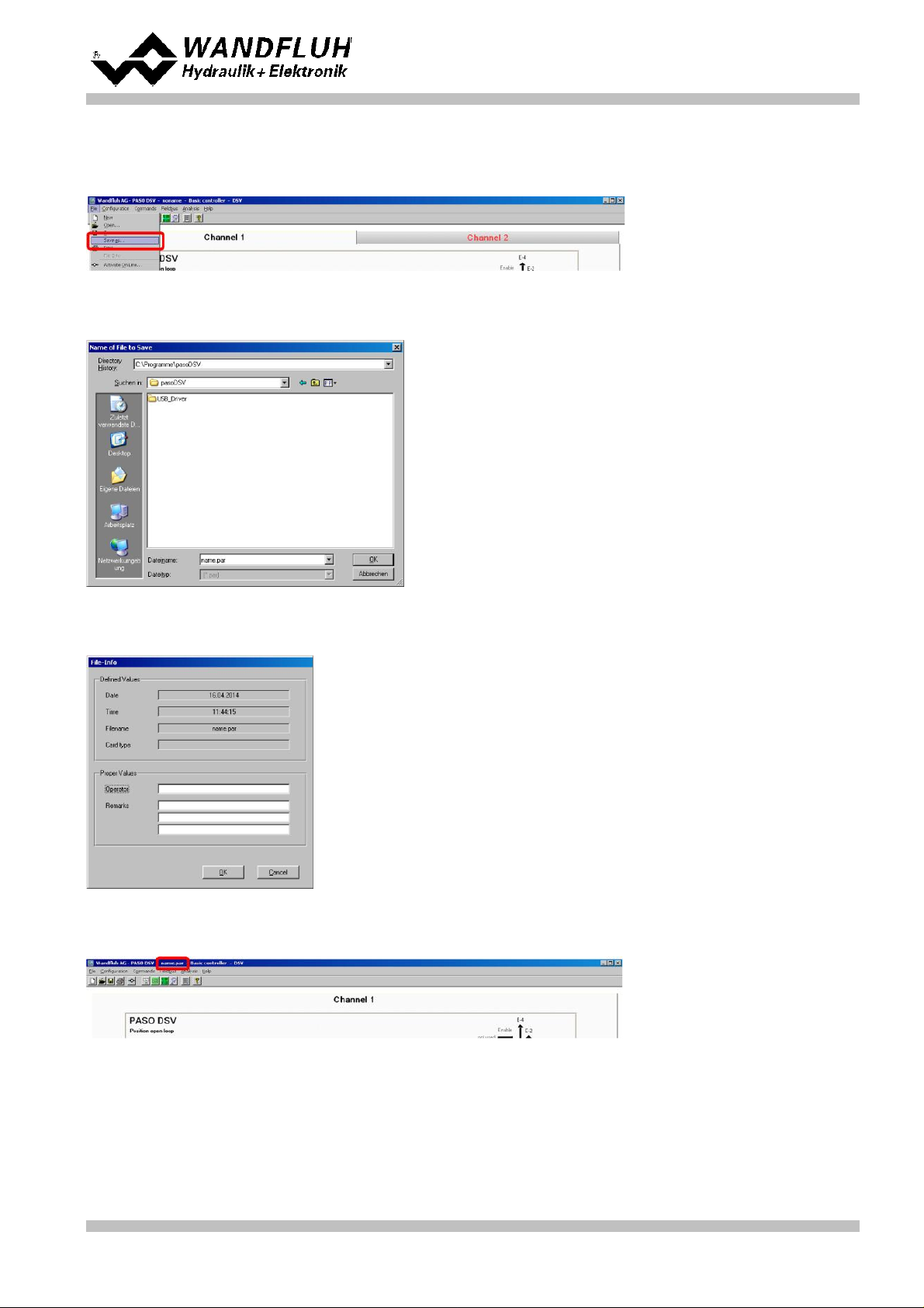
Step by Step Instruction for Controller Electronics DSV
5.16 Save parameters in a file (optional)
Select "File - Save as ..."
Enter the directory and file name, afterwards select "OK"
If required, enter the corresponding values to "Operator" and "Remarks", afterwards select "OK"
In the header line the corresponding file name appears
Wandfluh AG
Postfach
CH-3714 Frutigen
Tel: +41 33 672 72 72
Fax: +41 33 672 72 12
Email: sales@wandfluh.com
Internet: www.wandfluh.com
Page 33
Edition 09 13
DSV_StepByStep_d.pdf
Page 34

Step by Step Instruction for Controller Electronics DSV
5.17 Activate PASO On Line mode
Select "File - Activate On Line"
Select "Program the Wandfluh-Electronic with the new actual data?"
Select "OK"
Select "send all parameters without the valve specific parameters"
Select "OK"
Wait, until all parameters are sent to the DSV Electronics
In the status line the message "On-Line" appears
Wandfluh AG
Postfach
CH-3714 Frutigen
Tel: +41 33 672 72 72
Fax: +41 33 672 72 12
Email: sales@wandfluh.com
Internet: www.wandfluh.com
Page 34
Edition 09 13
DSV_StepByStep_d.pdf
Page 35
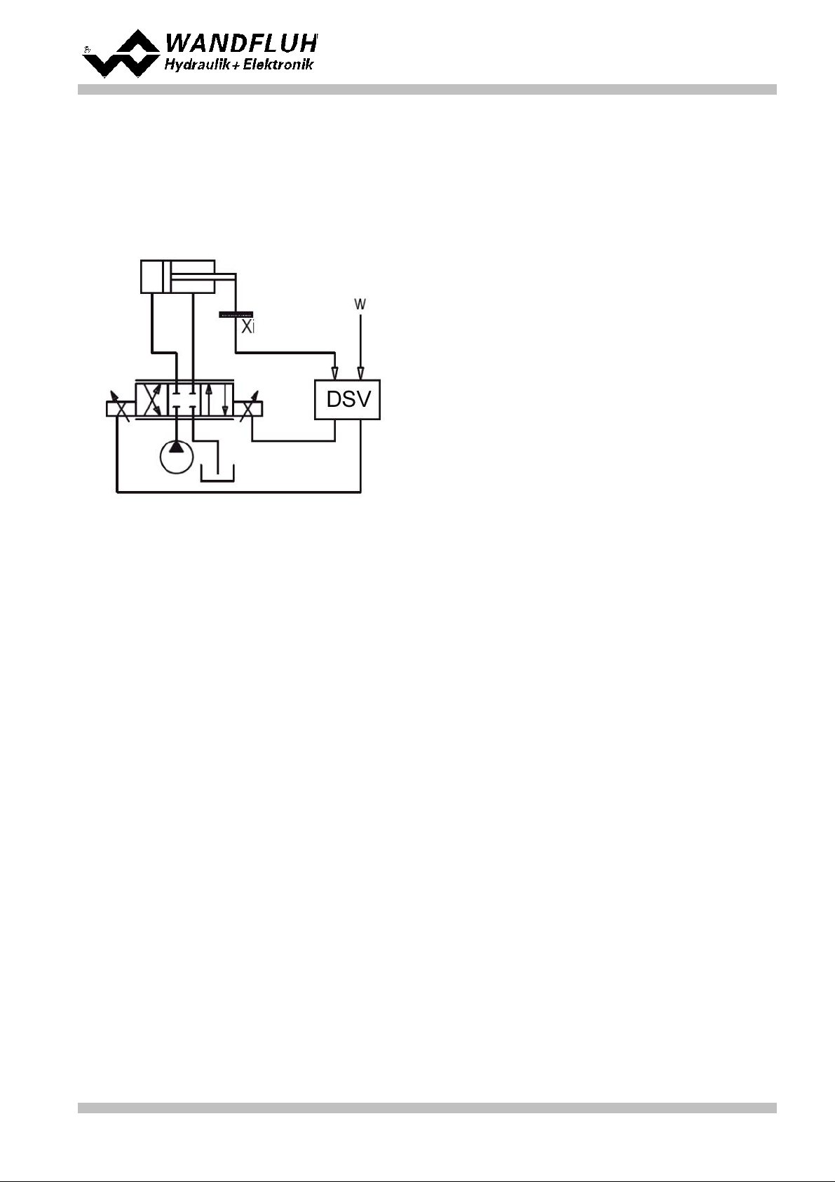
Step by Step Instruction for Controller Electronics DSV
Controller mode:
Position closed loop (2-sol)
Command signal:
0 ... 10V on analog input 1
Feedback signal:
0 ... 10V on analog input 2
max. working stroke:
0 ... 500mm
desired working
stroke:
20 ... 480mm
Valve connection:
4/3-way proportional valve, extend = solenoid A, retract = solenoid B
Enable channel:
external via digital input 1
6
Setup Instruction Position closed loop (2-sol)
6.1 Introduction
This guide shows with an example how to set channel 1 of the DSV Electronics as a position controller.
Pretended:
Wandfluh AG
Postfach
CH-3714 Frutigen
Tel: +41 33 672 72 72
Fax: +41 33 672 72 12
Email: sales@wandfluh.com
Internet: www.wandfluh.com
Page 35
Edition 09 13
DSV_StepByStep_d.pdf
Page 36

Step by Step Instruction for Controller Electronics DSV
1.
Activate PASO Off Line mode
2.
Select controller mode
3.
Select valve type
4.
Scale command signal
5.
Scale feedback signal
6.
Set command values fixed (optional)
7.
Set command generator
8.
Set windows
9.
Set controller
10.
Set solenoid driver 1
11.
Set solenoid driver 2
12.
Set error evaluation (optional)
13.
Set function (optional)
14.
Set enable channel
15.
Save parameters in a file (optional)
16.
Activate PASO On Line mode
17.
By activating the digital input 1, the channel 1 will be released in the controller mode "Position open loop"
The following steps are necessary (steps with the remark "optional" are only necessary if needed):
37
37
37
37
38
38
38
38
39
39
40
40
40
40
41
42
Wandfluh AG
Postfach
CH-3714 Frutigen
Tel: +41 33 672 72 72
Fax: +41 33 672 72 12
Email: sales@wandfluh.com
Internet: www.wandfluh.com
Page 36
Edition 09 13
DSV_StepByStep_d.pdf
Page 37

6.2 Activate PASO Off Line mode
Parameter
Description
Controller mode
Select controller mode "Position closed loop (2-sol)"
Displayed unit
Select the desired unit (in the example "mm")
Parameter
Description
Solenoid type
Select the solenoid type of the connected valve (in the example "Proportional solenoid
with current measurement")
Valve type
Select the valve type of the connected valve (in the example "Standard 2-solenoid")
Parameter
Description
Signal type
Set the signal type from the command signal generator (in the example "Voltage")
Used analog input
If the parameter "Signal type" is set to "Voltage" or "Current", the input where the
command signal generator is connect can be selected here (in the example "AnaInp1
[V]")
Used digital input
If the parameter "Signal type" is set to "Digital", "Frequency" or "PWM", the input where
the command signal generator is connect can be selected here
Cablebreak
detection
If the parameter "Signal type" is set to "Current", "Frequency" or "PWM", a cablebreak
detection of the command signal generator can be activated
Lower cablebreak
limit
If the parameter "Cablebreak detection" is set to "yes", the lower limit of this detection
can be set here
(command value < lower cablebreak limit = cablebreak)
Upper cablebreak
limit
If the parameter "Cablebreak detection" is set to "yes", the upper limit of this detection
can be set here
(command value > upper cablebreak limit = cablebreak)
Select "File - Activate Off Line"
Select "OK"
In the status line the message "Off-Line" appears
Step by Step Instruction for Controller Electronics DSV
6.3 Select controller mode
All other parameters in this window will be set later.
6.4 Select valve type
The remaining parameters have no function in this control mode
6.5 Scale command signal
Wandfluh AG
Postfach
CH-3714 Frutigen
Tel: +41 33 672 72 72
Fax: +41 33 672 72 12
Email: sales@wandfluh.com
Internet: www.wandfluh.com
Page 37
Edition 09 13
DSV_StepByStep_d.pdf
Page 38

Step by Step Instruction for Controller Electronics DSV
min interface
Set the minimum command signal level (in the example 0V)
max interface
Set the maximum command signal level (in the example 10V)
min reference
Set the minimum desired stroke (correspond to the stroke at "min interface", in the
example 20mm)
max reference
Set the maximum desired stroke (correspond to the stroke at "max interface", in the
example 480mm)
Parameter
Description
Signal type
Set the signal type from the feedback signal generator (in the example "Voltage")
Used analog input
If the parameter "Signal type" is set to "Voltage" or "Current", the input where the
feedback signal generator is connect can be selected here (in the example "AnaInp2
[V]")
Used digital input
If the parameter "Signal type" is set to "Digital", "Frequency" or "PWM", the input where
the feedback signal generator is connect can be selected here
Cablebreak
detection
If the parameter "Signal type" is set to "Current", "Frequency" or "PWM", a cablebreak
detection of the feedback signal generator can be activated
Lower cablebreak
limit
If the parameter "Cablebreak detection" is set to "yes", the lower limit of this detection
can be set here
(feedback value < lower cablebreak limit = cablebreak)
Upper cablebreak
limit
If the parameter "Cablebreak detection" is set to "yes", the upper limit of this detection
can be set here
(feedback value > upper cablebreak limit = cablebreak)
min interface
Set the minimum feedback signal level
(correspond to the feedback signal level at "min reference", in the example 0V)
max interface
Set the maximum feedback signal level
(correspond to the feedback signal level at "max reference", in the example 10V)
min reference
Set the minimum possible stroke (in the example 0mm)
max reference
Set the maximum possible stroke (in the example 500mm)
Parameter
Description
Enable
Enable the fixed command value function
Selection 1
Set the desired digital input for the fixed command value 1
Fixed command
value 1
Set the desired command value for the fixed command value 1. This value becomes the
active command value if the digital from "Selection 1" is activated
Parameter
Description
Speed +
This will set the extend speed of the system
(extend = positive control deviation => command > feedback)
Speed -
This will set the retract speed of the system
(retract = negative control deviation => command < feedback)
Parameter
Description
Target window type
Switch on/off the target window function
Target window threshold
Defines the target window range
(control deviation < target window threshold = target window reached)
Target window delay time
Delay time when falling below and exceeding the target window threshold
The remaining parameters have no function in this control mode
6.6 Scale feedback signal
6.7 Set command values fixed (optional)
6.8 Set speed (optional)
6.9 Set windows
Wandfluh AG
Postfach
CH-3714 Frutigen
Tel: +41 33 672 72 72
Fax: +41 33 672 72 12
Email: sales@wandfluh.com
Internet: www.wandfluh.com
Page 38
Edition 09 13
DSV_StepByStep_d.pdf
Page 39
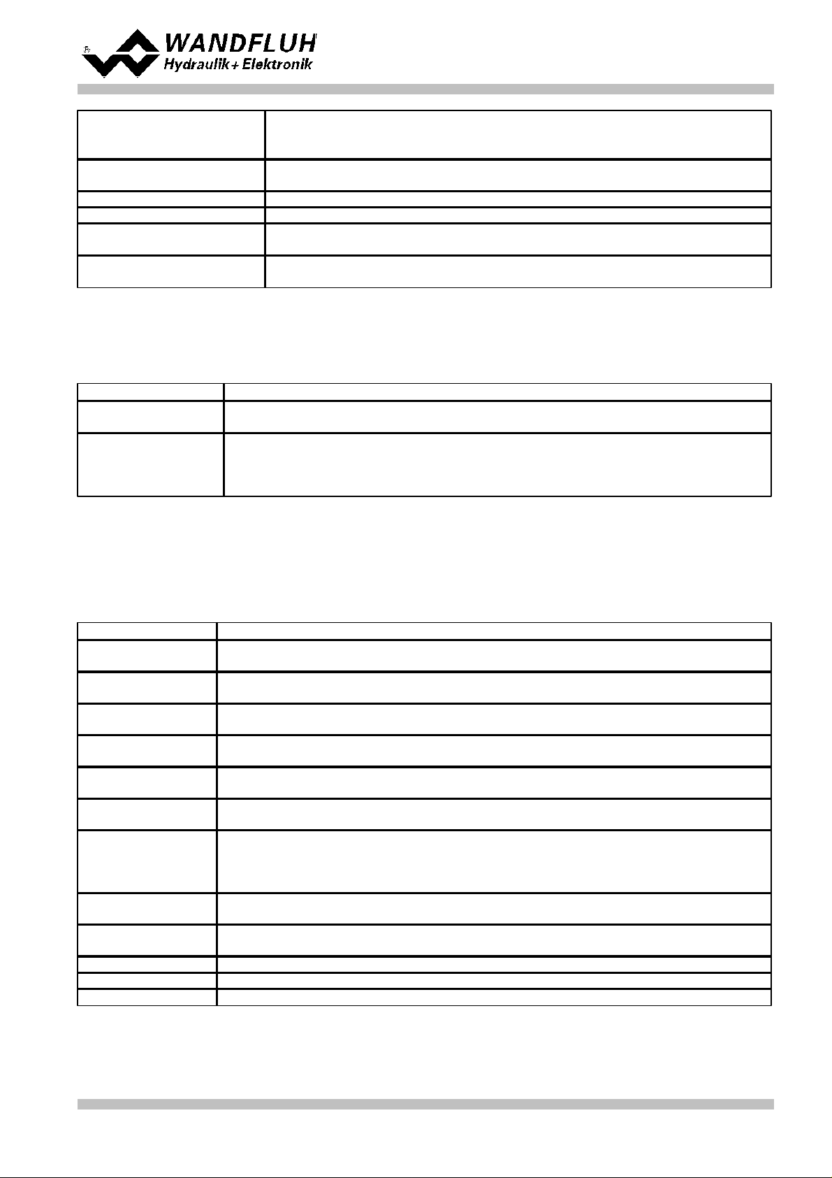
Trailing window type
Switch on/off the trailing window function
ATTENTION: With "on with error", the solenoid outputs will be disabled as
soon as the trailing window is active!
Trailing window threshold
Defines the trailing window range
(control deviation < trailing window threshold = trailing window reached)
Trailing window delay time
Delay time when falling below and exceeding the trailing window threshold
Solenoid-Off window type
Switch on/off the Solenoid-Off window function
Solenoid-Off window
threshold
Defines the Solenoid-Off window range
(control deviation < Solenoid-Off window threshold = solenoid are blocked)
Solenoid-Off window delay
time
Delay time when falling below and exceeding the Solenoid-Off window threshold
6.10 Set controller
Parameter
Description
Command feed
forward
In this control mode, this parameter must be set to 0
Velocity feed forward
This will accelerate the driving off of the cylinder. The change of the command value
(the increase speed of the command value) is multiplied with this factor and added to
the correcting variable of the controller. If this factor is 0, no command value addition is
added to the correcting variable.
Parameter
Description
Solenoid output
Select the output, where the solenoid for the extension is connected (in the example
"SolOutA")
Enable
Selection, if the solenoid output is constantly enabled (selection "on"), constantly
disabled (selection "off") or if it depends on a digital input (selection "external")
Dig. input
If the parameter "Enable" is set to "external", the corresponding digital input can be
selected here
Inversion
If a solenoid with a inverse function is used, this selection should be "yes", otherwise
"no"
Solenoid always
active
In this control mode, this parameter must always be set to "no"
Cablebreak
detection
If the cablebreak detection for the solenoid output is desired, this selection should be
"yes", otherwise "no"
Characteristic
optimisation
If the characteristic optimisation is desired, this selection should be "yes", otherwise
"no".
(the settings for the characteristic optimisation is made in the Tab-window
"Characteristic optimisation")
Imin
Set the desired minimum current for solenoid A.
The Imin should be set in a way that the axis just moved slightly at this value.
Imax
Set the desired maximum current for solenoid A.
The Imax should be approx. the nominal current from the solenoid +5%
Dither function
The dither function should be activated (Selection "on")
Dither frequency
Set the desired dither frequency value
Dither level
Set the desired dither level value
General
Step by Step Instruction for Controller Electronics DSV
PID controller
Using the parameters of the PID controller the control behavior can be set. Because the position control is a
dynamic control, the I-part can be omitted in many cases.
6.11 Set solenoid driver 1
The remaining parameters have no function in this control mode
Wandfluh AG
Postfach
CH-3714 Frutigen
Tel: +41 33 672 72 72
Fax: +41 33 672 72 12
Email: sales@wandfluh.com
Internet: www.wandfluh.com
Page 39
Edition 09 13
DSV_StepByStep_d.pdf
Page 40
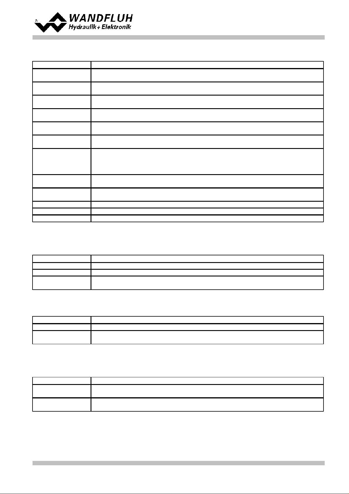
6.12 Set solenoid driver 2
Parameter
Description
Solenoid output
Select the output, where the solenoid for the retracting is connected (in the example
"SolOutB")
Enable
Selection, if the solenoid output is constantly enabled (selection "on"), constantly
disabled (selection "off") or if it depends on a digital input (selection "external")
Dig. input
If the parameter "Enable" is set to "external", the corresponding digital input can be
selected here
Inversion
If a solenoid with a inverse function is used, this selection should be "yes", otherwise
"no"
Solenoid always
active
In this control mode, this parameter must always be set to "no"
Cablebreak
detection
If the cablebreak detection for the solenoid output is desired, this selection should be
"yes", otherwise "no"
Characteristic
optimisation
If the characteristic optimisation is desired, this selection should be "yes", otherwise
"no".
(the settings for the characteristic optimisation is made in the Tab-window
"Characteristic optimisation")
Imin
Set the desired minimum current for solenoid B.
The Imin should be set in a way that the axis just moved slightly at this value.
Imax
Set the desired maximum current for solenoid B.
The Imax should be approx. the nominal current from the solenoid +5%
Dither function
The dither function should be activated (Selection "on")
Dither frequency
Set the desired dither frequency value
Dither level
Set the desired dither level value
Parameter
Description
Selection
Here one can choose what error should activate the selected digital output
Dig. output
As soon as one of the selected error occurs, the selected digital output will be activated
Error action
With error "Cablebreak command signal" and "Cablebreak feedback signal", the desired
error action can be set. The default setting is "Solenoid 1 + 2 off"
Parameter
Description
Selection
Here one can choose what function should activate the selected digital output
Dig. output
As soon as one of the selected functions occurs, the selected digital output will be
activated
Parameter
Description
Enable
Selection, if the channel is constantly enabled (selection "on"), constantly disabled
(selection "off") of if it depends on a digital input (selection "external")
Dig. input
If the parameter "Enable" is set to *external", the corresponding digital input can be
selected here (in the example "DigInp1")
Step by Step Instruction for Controller Electronics DSV
The remaining parameters have no function in this control mode
6.13 Set error evaluation (optional)
6.14 Set function (optional)
6.15 Set enable channel
Wandfluh AG
Postfach
CH-3714 Frutigen
Tel: +41 33 672 72 72
Fax: +41 33 672 72 12
Email: sales@wandfluh.com
Internet: www.wandfluh.com
Page 40
Edition 09 13
DSV_StepByStep_d.pdf
Page 41

Step by Step Instruction for Controller Electronics DSV
6.16 Save parameters in a file (optional)
Select "File - Save as ..."
Enter the directory and file name, afterwards select "OK"
If required, enter the corresponding values to "Operator" and "Remarks", afterwards select "OK"
In the header line the corresponding file name appears
Wandfluh AG
Postfach
CH-3714 Frutigen
Tel: +41 33 672 72 72
Fax: +41 33 672 72 12
Email: sales@wandfluh.com
Internet: www.wandfluh.com
Page 41
Edition 09 13
DSV_StepByStep_d.pdf
Page 42

Step by Step Instruction for Controller Electronics DSV
6.17 Activate PASO On Line mode
Select "File - Activate On Line"
Select "Program the Wandfluh-Electronic with the new actual data?"
Select "OK"
Select "send all parameters without the valve specific parameters"
Select "OK"
Wait, until all parameters are sent to the DSV Electronics
In the status line the message "On-Line" appears
Wandfluh AG
Postfach
CH-3714 Frutigen
Tel: +41 33 672 72 72
Fax: +41 33 672 72 12
Email: sales@wandfluh.com
Internet: www.wandfluh.com
Page 42
Edition 09 13
DSV_StepByStep_d.pdf
Page 43

Step by Step Instruction for Controller Electronics DSV
Controller mode:
Speed control closed loop (2-sol)
Command signal:
0 ... 10V on analog input 1
Feedback signal:
0 ... 10V on analog input 3
max. working stroke:
0 ... 20l/min
desired working
stroke:
2 ... 18l/min
Valve connection:
4/3-way proportional valve, solenoid A = direction right, solenoid B = direction left
Enable channel:
external via digital input 1
7
Setup Instruction Speed control closed loop (2-sol)
7.1 Introduction
This guide shows with an example how to set channel 1 of the DSV Electronics as a speed controller.
Pretended:
Wandfluh AG
Postfach
CH-3714 Frutigen
Tel: +41 33 672 72 72
Fax: +41 33 672 72 12
Email: sales@wandfluh.com
Internet: www.wandfluh.com
Page 43
Edition 09 13
DSV_StepByStep_d.pdf
Page 44

Step by Step Instruction for Controller Electronics DSV
1.
Activate PASO Off Line mode
2.
Select controller mode
3.
Select valve type
4.
Scale command signal
5.
Scale feedback signal
6.
Set command values fixed (optional)
7.
Set command generator
8.
Set windows
9.
Set controller
10.
Set solenoid driver 1
11.
Set solenoid driver 2
12.
Set error evaluation (optional)
13.
Set function (optional)
14.
Set enable channel
15.
Save parameters in a file (optional)
16.
Activate PASO On Line mode
17.
By activating the digital input 1, the channel 1 will be released in the controller mode "Speed control closed
loop (2-sol)"
The following steps are necessary (steps with the remark "optional" are only necessary if needed):
45
45
45
45
46
46
46
46
47
47
48
48
48
48
49
50
Wandfluh AG
Postfach
CH-3714 Frutigen
Tel: +41 33 672 72 72
Fax: +41 33 672 72 12
Email: sales@wandfluh.com
Internet: www.wandfluh.com
DSV_StepByStep_d.pdf
Page 44
Edition 09 13
Page 45

7.2 Activate PASO Off Line mode
Parameter
Description
Controller mode
Select controller mode "Speed control closed loop (2-sol)
Displayed unit
Select the desired unit (in the example "l/min").
Parameter
Description
Solenoid type
Select the solenoid type of the connected valve (in the example "Proportional solenoid
with current measurement")
Valve type
Select the valve type of the connected valve (in the example "Standard 2-solenoid")
Parameter
Description
Signal type
Set the signal type from the command signal generator (in the example "Voltage")
Used analog input
If the parameter "Signal type" is set to "Voltage" or "Current", the input where the
command signal generator is connect can be selected here (in the example "AnaInp1
[V]")
Used digital input
If the parameter "Signal type" is set to "Digital", "Frequency" or "PWM", the input where
the command signal generator is connect can be selected here
Cablebreak
detection
If the parameter "Signal type" is set to "Current", "Frequency" or "PWM", a cablebreak
detection of the command signal generator can be activated
Lower cablebreak
limit
If the parameter "Cablebreak detection" is set to "yes", the lower limit of this detection
can be set here
(command value < lower cablebreak limit = cablebreak)
Upper cablebreak
limit
If the parameter "Cablebreak detection" is set to "yes", the upper limit of this detection
can be set here
(command value > upper cablebreak limit = cablebreak)
Select "File - Activate Off Line"
Select "OK"
In the status line the message "Off-Line" appears
Step by Step Instruction for Controller Electronics DSV
7.3 Select controller mode
All other parameters in this window will be set later.
7.4 Select valve type
The remaining parameters have no function in this control mode
7.5 Scale command signal
Wandfluh AG
Postfach
CH-3714 Frutigen
Tel: +41 33 672 72 72
Fax: +41 33 672 72 12
Email: sales@wandfluh.com
Internet: www.wandfluh.com
Page 45
Edition 09 13
DSV_StepByStep_d.pdf
Page 46

Step by Step Instruction for Controller Electronics DSV
min interface
Set the minimum command signal level (in the example 0V)
max interface
Set the maximum command signal level (in the example 10V)
min reference
Set the minimum desired speed (correspond to the speed at "min interface", in the
example 2l/min)
max reference
Set the maximum desired speed (correspond to the speed at "max interface", in the
example 18l/min)
Parameter
Description
Signal type
Set the signal type from the feedback signal generator (in the example "Voltage")
Used analog input
If the parameter "Signal type" is set to "Voltage" or "Current", the input where the
feedback signal generator is connect can be selected here (in the example "AnaInp2
[V]")
Used digital input
If the parameter "Signal type" is set to "Digital", "Frequency" or "PWM", the input where
the feedback signal generator is connect can be selected here
Cablebreak
detection
If the parameter "Signal type" is set to "Current", "Frequency" or "PWM", a cablebreak
detection of the feedback signal generator can be activated
Lower cablebreak
limit
If the parameter "Cablebreak detection" is set to "yes", the lower limit of this detection
can be set here
(feedback value < lower cablebreak limit = cablebreak)
Upper cablebreak
limit
If the parameter "Cablebreak detection" is set to "yes", the upper limit of this detection
can be set here
(feedback value > upper cablebreak limit = cablebreak)
min interface
Set the minimum feedback signal level
(correspond to the feedback signal level at "min reference", in the example 0V)
max interface
Set the maximum feedback signal level
(correspond to the feedback signal level at "max reference", in the example 10V)
min reference
Set the minimum possible speed (in the example 0l/min)
max reference
Set the maximum possible speed (in the example 20l/min)
Parameter
Description
Enable
Enable the fixed command value function
Selection 1
Set the desired digital input for the fixed command value 1
Fixed command
value 1
Set the desired command value for the fixed command value 1. This value becomes the
active command value if the digital from "Selection 1" is activated
Parameter
Description
Speed +
This will set the speed rise speed of the system
(speed rise = positive control deviation => command > feedback)
Speed -
This will set the speed reducing speed of the system
(speed reducing = negative control deviation => command < feedback)
Parameter
Description
Target window type
Switch on/off the target window function
Target window threshold
Defines the target window range
(control deviation < target window threshold = target window reached)
Target window delay time
Delay time when falling below and exceeding the target window threshold
The remaining parameters have no function in this control mode
7.6 Scale feedback signal
7.7 Set command values fixed (optional)
7.8 Set speed (optional)
7.9 Set windows
Wandfluh AG
Postfach
CH-3714 Frutigen
Tel: +41 33 672 72 72
Fax: +41 33 672 72 12
Email: sales@wandfluh.com
Internet: www.wandfluh.com
Page 46
Edition 09 13
DSV_StepByStep_d.pdf
Page 47

Step by Step Instruction for Controller Electronics DSV
Trailing window type
Switch on/off the trailing window function
ATTENTION: With "on with error", the solenoid outputs will be disabled as
soon as the trailing window is active!
Trailing window threshold
Defines the trailing window range
(control deviation < trailing window threshold = trailing window reached)
Trailing window delay time
Delay time when falling below and exceeding the trailing window threshold
Solenoid-Off window type
Switch on/off the Solenoid-Off window function
Solenoid-Off window
threshold
Defines the Solenoid-Off window range
(control deviation < Solenoid-Off window threshold = solenoid are blocked)
Solenoid-Off window delay
time
Delay time when falling below and exceeding the Solenoid-Off window threshold
Parameter
Description
Command feed
forward
The command value is multiplied with this factor and added to the correcting variable of
the controller. If this factor is 0, no command value proportion is added to the
correcting variable. Ideally, this value is set so that the deviation in the open loop is as
small as possible. The deviation will not have the same size over the whole range.
Thus, the smallest possible deviation can be set in the area where one will be mainly
operate.
Velocity feed forward
In this control mode, this parameter must be set to 0
Parameter
Description
Solenoid output
Select the output, where the solenoid for the right turning is connected (in the example
"SolOutA")
Enable
Selection, if the solenoid output is constantly enabled (selection "on"), constantly
disabled (selection "off") or if it depends on a digital input (selection "external")
Dig. input
If the parameter "Enable" is set to "external", the corresponding digital input can be
selected here
Inversion
If a solenoid with a inverse function is used, this selection should be "yes", otherwise
"no"
Solenoid always
active
In this control mode, this parameter must always be set to "no"
Cablebreak
detection
If the cablebreak detection for the solenoid output is desired, this selection should be
"yes", otherwise "no"
Characteristic
optimisation
If the characteristic optimisation is desired, this selection should be "yes", otherwise
"no".
(the settings for the characteristic optimisation is made in the Tab-window
"Characteristic optimisation")
Imin
Set the desired minimum current for solenoid A. The Imin should set in the way that with
this value the desired minimum speed will be reached
Imax
Set the desired maximum current for solenoid A.
The Imax should be approx. the nominal current from the solenoid +5%
Dither function
The dither function should be activated (Selection "on")
Dither frequency
Set the desired dither frequency value
Dither level
Set the desired dither level value
In this control mode, the "Solenoid-Off" window must be set to "off".
7.10 Set controller
General
PID-controller
Using the parameters of the PID controller the control behavior can be set. Because the speed control is a
dynamic control, the I-part can be omitted in many cases.
7.11 Set solenoid driver 1
The remaining parameters have no function in this control mode
Wandfluh AG
Postfach
CH-3714 Frutigen
Tel: +41 33 672 72 72
Fax: +41 33 672 72 12
Email: sales@wandfluh.com
Internet: www.wandfluh.com
Page 47
Edition 09 13
DSV_StepByStep_d.pdf
Page 48

7.12 Set solenoid driver 2
Parameter
Description
Solenoid output
Select the output, where the solenoid for the left turning is connected (in the example
"SolOutB")
Enable
Selection, if the solenoid output is constantly enabled (selection "on"), constantly
disabled (selection "off") or if it depends on a digital input (selection "external")
Dig. input
If the parameter "Enable" is set to "external", the corresponding digital input can be
selected here
Inversion
If a solenoid with a inverse function is used, this selection should be "yes", otherwise
"no"
Solenoid always
active
In this control mode, this parameter must always be set to "no"
Cablebreak
detection
If the cablebreak detection for the solenoid output is desired, this selection should be
"yes", otherwise "no"
Characteristic
optimisation
If the characteristic optimisation is desired, this selection should be "yes", otherwise
"no".
(the settings for the characteristic optimisation is made in the Tab-window
"Characteristic optimisation")
Imin
Set the desired minimum current for solenoid A. The Imin should set in the way that with
this value the desired minimum speed will be reached
Imax
Set the desired maximum current for solenoid A.
The Imax should be approx. the nominal current from the solenoid +5%
Dither function
The dither function should be activated (Selection "on")
Dither frequency
Set the desired dither frequency value
Dither level
Set the desired dither level value
Parameter
Description
Selection
Here one can choose what error should activate the selected digital output
Dig. output
As soon as one of the selected error occurs, the selected digital output will be activated
Error action
With error "Cablebreak command signal" and "Cablebreak feedback signal", the desired
error action can be set. The default setting is "Solenoid 1 + 2 off"
Parameter
Description
Selection
Here one can choose what function should activate the selected digital output
Dig. output
As soon as one of the selected functions occurs, the selected digital output will be
activated
Parameter
Description
Enable
Selection, if the channel is constantly enabled (selection "on"), constantly disabled
(selection "off") of if it depends on a digital input (selection "external")
Dig. input
If the parameter "Enable" is set to *external", the corresponding digital input can be
selected here (in the example "DigInp1")
Step by Step Instruction for Controller Electronics DSV
The remaining parameters have no function in this control mode
7.13 Set error evaluation (optional)
7.14 Set function (optional)
7.15 Set enable channel
Wandfluh AG
Postfach
CH-3714 Frutigen
Tel: +41 33 672 72 72
Fax: +41 33 672 72 12
Email: sales@wandfluh.com
Internet: www.wandfluh.com
Page 48
Edition 09 13
DSV_StepByStep_d.pdf
Page 49

Step by Step Instruction for Controller Electronics DSV
7.16 Save parameters in a file (optional)
Select "File - Save as ..."
Enter the directory and file name, afterwards select "OK"
If required, enter the corresponding values to "Operator" and "Remarks", afterwards select "OK"
In the header line the corresponding file name appears
Wandfluh AG
Postfach
CH-3714 Frutigen
Tel: +41 33 672 72 72
Fax: +41 33 672 72 12
Email: sales@wandfluh.com
Internet: www.wandfluh.com
Page 49
Edition 09 13
DSV_StepByStep_d.pdf
Page 50

Step by Step Instruction for Controller Electronics DSV
7.17 Activate PASO On Line mode
Select "File - Activate On Line"
Select "Program the Wandfluh-Electronic with the new actual data?"
Select "OK"
Select "send all parameters without the valve specific parameters"
Select "OK"
Wait, until all parameters are sent to the DSV Electronics
In the status line the message "On-Line" appears
Wandfluh AG
Postfach
CH-3714 Frutigen
Tel: +41 33 672 72 72
Fax: +41 33 672 72 12
Email: sales@wandfluh.com
Internet: www.wandfluh.com
Page 50
Edition 09 13
DSV_StepByStep_d.pdf
Page 51
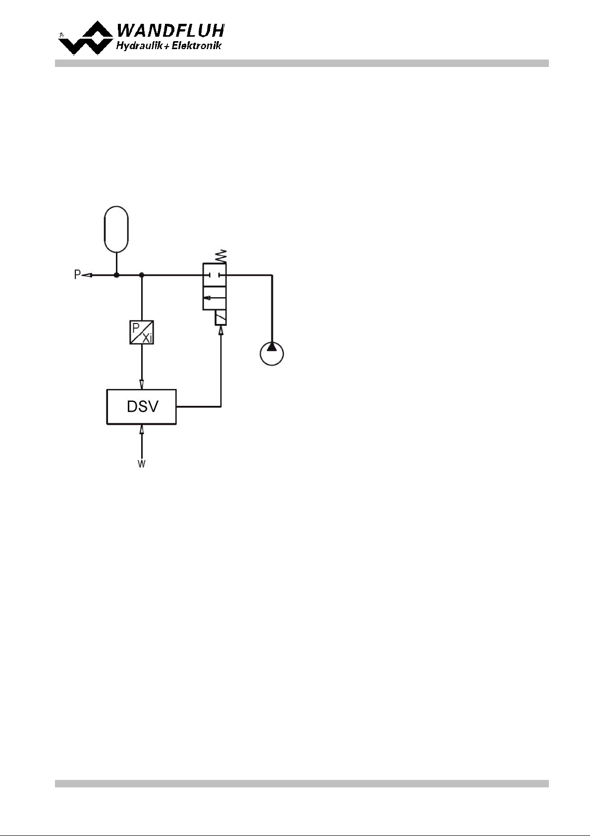
Step by Step Instruction for Controller Electronics DSV
Controller mode:
2-point controller (1-sol)
Command signal:
0 ... 10V on analog input 1
Feedback signal:
0 ... 10V on analog input 3
max. working stroke:
0 ... 200bar
desired working
stroke:
0 ... 200bar
Control behavior:
p < command pressure, accumulator need to be charged
Valve connection:
solenoid A = 2/2-way switching valve for charging the accumulator
Enable channel:
external via digital input 1
8
Setup Instruction 2-point controller (1-sol)
8.1 Introduction
This guide shows with an example how to set channel 1 of the DSV Electronics as a 1-point controller
(1-solenoid).
Pretended:
Wandfluh AG
Postfach
CH-3714 Frutigen
Tel: +41 33 672 72 72
Fax: +41 33 672 72 12
Email: sales@wandfluh.com
Internet: www.wandfluh.com
Page 51
Edition 09 13
DSV_StepByStep_d.pdf
Page 52
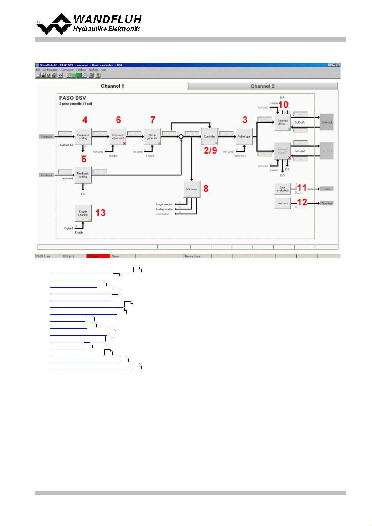
Step by Step Instruction for Controller Electronics DSV
1.
Activate PASO Off Line mode
2.
Select controller mode
3.
Select valve type
4.
Scale command signal
5.
Scale feedback signal
6.
Set command values fixed (optional)
7.
Set command generator
8.
Set windows
9.
Set controller
10.
Set solenoid driver 1
11.
Set error evaluation (optional)
12.
Set function (optional)
13.
Set enable channel
14.
Save parameters in a file (optional)
15.
Activate PASO On Line mode
16.
By activating the digital input 1, the channel 1 will be released in the controller mode "2-point controller
(1-sol)"
The following steps are necessary (steps with the remark "optional" are only necessary if needed):
53
53
53
53
54
54
54
54
55
55
55
56
56
57
58
Wandfluh AG
Postfach
CH-3714 Frutigen
Tel: +41 33 672 72 72
Fax: +41 33 672 72 12
Email: sales@wandfluh.com
Internet: www.wandfluh.com
DSV_StepByStep_d.pdf
Page 52
Edition 09 13
Page 53

8.2 Activate PASO Off Line mode
Parameter
Description
Controller mode
Select controller mode "2-point controller (1-sol)"
Displayed unit
Select the desired unit (in the example "bar")
Parameter
Description
Solenoid type
Select the solenoid type of the connected valve (in the example "Proportional solenoid
with current measurement")
Valve type
Select the valve type of the connected valve (in the example "Standard 2-solenoid")
Parameter
Description
Signal type
Set the signal type from the command signal generator (in the example "Voltage")
Used analog input
If the parameter "Signal type" is set to "Voltage" or "Current", the input where the
command signal generator is connect can be selected here (in the example "AnaInp1
[V]")
Used digital input
If the parameter "Signal type" is set to "Digital", "Frequency" or "PWM", the input where
the command signal generator is connect can be selected here
Cablebreak
detection
If the parameter "Signal type" is set to "Current", "Frequency" or "PWM", a cablebreak
detection of the command signal generator can be activated
Lower cablebreak
limit
If the parameter "Cablebreak detection" is set to "yes", the lower limit of this detection
can be set here
(command value < lower cablebreak limit = cablebreak)
Upper cablebreak
limit
If the parameter "Cablebreak detection" is set to "yes", the upper limit of this detection
can be set here
(command value > upper cablebreak limit = cablebreak)
Select "File - Activate Off Line"
Select "OK"
In the status line the message "Off-Line" appears
Step by Step Instruction for Controller Electronics DSV
8.3 Select controller mode
All other parameters in this window will be set later.
8.4 Select valve type
The remaining parameters have no function in this control mode
8.5 Select controller mode "2-point controller (1-sol)"
Wandfluh AG
Postfach
CH-3714 Frutigen
Tel: +41 33 672 72 72
Fax: +41 33 672 72 12
Email: sales@wandfluh.com
Internet: www.wandfluh.com
Page 53
Edition 09 13
DSV_StepByStep_d.pdf
Page 54

Step by Step Instruction for Controller Electronics DSV
min interface
Set the minimum command signal level (in the example 0V)
max interface
Set the maximum command signal level (in the example 10V)
min reference
Set the minimum desired pressure (correspond to the pressure at "min interface", in the
example 0°C)
max reference
Set the maximum desired pressure (correspond to the pressure at "max interface", in
the example 50°C)
Parameter
Description
Signal type
Set the signal type from the feedback signal generator (in the example "Voltage")
Used analog input
If the parameter "Signal type" is set to "Voltage" or "Current", the input where the
feedback signal generator is connect can be selected here (in the example "AnaInp2
[V]")
Used digital input
If the parameter "Signal type" is set to "Digital", "Frequency" or "PWM", the input where
the feedback signal generator is connect can be selected here
Cablebreak
detection
If the parameter "Signal type" is set to "Current", "Frequency" or "PWM", a cablebreak
detection of the feedback signal generator can be activated
Lower cablebreak
limit
If the parameter "Cablebreak detection" is set to "yes", the lower limit of this detection
can be set here
(feedback value < lower cablebreak limit = cablebreak)
Upper cablebreak
limit
If the parameter "Cablebreak detection" is set to "yes", the upper limit of this detection
can be set here
(feedback value > upper cablebreak limit = cablebreak)
min interface
Set the minimum feedback signal level
(correspond to the feedback signal level at "min reference", in the example 0V)
max interface
Set the maximum feedback signal level
(correspond to the feedback signal level at "max reference", in the example 10V)
min reference
Set the minimum possible pressure (in the example 0bar)
max reference
Set the maximum possible pressure (in the example 200bar)
Parameter
Description
Enable
Enable the fixed command value function
Selection 1
Set the desired digital input for the fixed command value 1
Fixed command
value 1
Set the desired command value for the fixed command value 1. This value becomes the
active command value if the digital from "Selection 1" is activated
Parameter
Description
Speed +
This will set the pressure rise speed of the system
(pressure rise = positive control deviation => command > feedback)
Speed -
This will set the pressure reducing speed of the system
(pressure reducing = negative control deviation => command < feedback)
Parameter
Description
Target window type
Switch on/off the target window function
Target window threshold
Defines the target window range
(control deviation < target window threshold = target window reached)
Target window delay time
Delay time when falling below and exceeding the target window threshold
The remaining parameters have no function in this control mode
8.6 Scale feedback signal
8.7 Set command values fixed (optional)
8.8 Set speed (optional)
8.9 Set windows
Wandfluh AG
Postfach
CH-3714 Frutigen
Tel: +41 33 672 72 72
Fax: +41 33 672 72 12
Email: sales@wandfluh.com
Internet: www.wandfluh.com
Page 54
Edition 09 13
DSV_StepByStep_d.pdf
Page 55
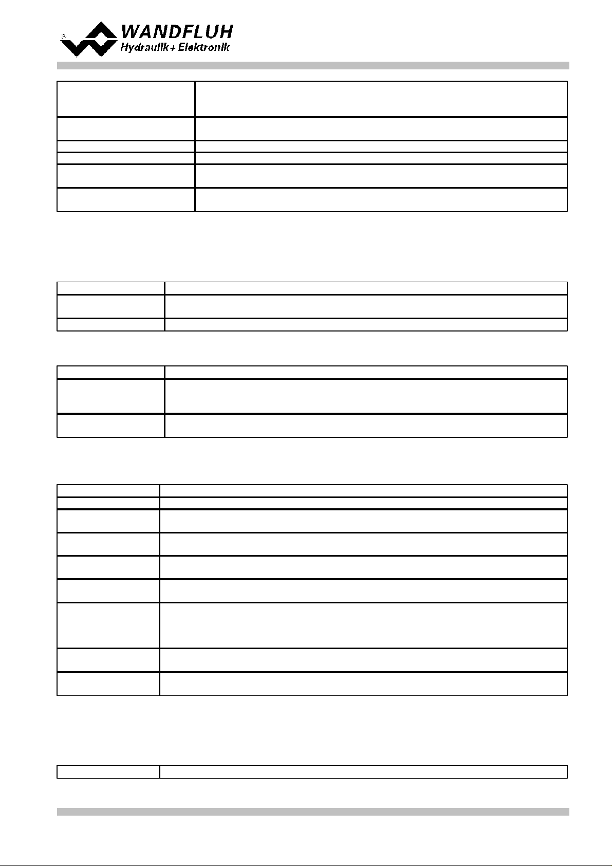
Trailing window type
Switch on/off the trailing window function
ATTENTION: With "on with error", the solenoid outputs will be disabled as
soon as the trailing window is active!
Trailing window threshold
Defines the trailing window range
(control deviation < trailing window threshold = trailing window reached)
Trailing window delay time
Delay time when falling below and exceeding the trailing window threshold
Solenoid-Off window type
Switch on/off the Solenoid-Off window function
Solenoid-Off window
threshold
Defines the Solenoid-Off window range
(control deviation < Solenoid-Off window threshold = solenoid are blocked)
Solenoid-Off window delay
time
Delay time when falling below and exceeding the Solenoid-Off window threshold
8.10 Set controller
Parameter
Description
Command feed
forward
In this control mode, this parameter must be set to 0
Velocity feed forward
In this control mode, this parameter must be set to 0
Parameter
Description
Threshold 1
Control deviation, at which the solenoid output from solenoid driver 1 will be set to
100%
(with increasing control deviation)
Threshold 2
Control deviation, at which the solenoid output from solenoid driver 1 will be set to 0%
(with decreasing control deviation)
Parameter
Description
Solenoid output
Select the output, where the solenoid is connected (in the example "SolOutA")
Enable
Selection, if the solenoid output is constantly enabled (selection "on"), constantly
disabled (selection "off") or if it depends on a digital input (selection "external")
Dig. input
If the parameter "Enable" is set to "external", the corresponding digital input can be
selected here
Inversion
If a solenoid with a inverse function is used, this selection should be "yes", otherwise
"no"
Cablebreak
detection
If the cablebreak detection for the solenoid output is desired, this selection should be
"yes", otherwise "no"
Characteristic
optimisation
If the characteristic optimisation is desired, this selection should be "yes", otherwise
"no".
(the settings for the characteristic optimisation is made in the Tab-window
"Characteristic optimisation")
Reduction time
If a power reduction on the solenoid output is desired, the time after the reduction will
start can be set here. With a setting from "0ms", the power reduction is switched off.
Reduced value
If a power reduction on the solenoid output is desired, the value where the output will be
reduced to can be set here. With a setting from "100%", the reduction is switched off.
Parameter
Description
General
Step by Step Instruction for Controller Electronics DSV
n-point controller
8.11 Set solenoid driver 1
The remaining parameters have no function in this control mode
8.12 Set error evaluation (optional)
Wandfluh AG
Postfach
CH-3714 Frutigen
Tel: +41 33 672 72 72
Fax: +41 33 672 72 12
Email: sales@wandfluh.com
Internet: www.wandfluh.com
Page 55
Edition 09 13
DSV_StepByStep_d.pdf
Page 56
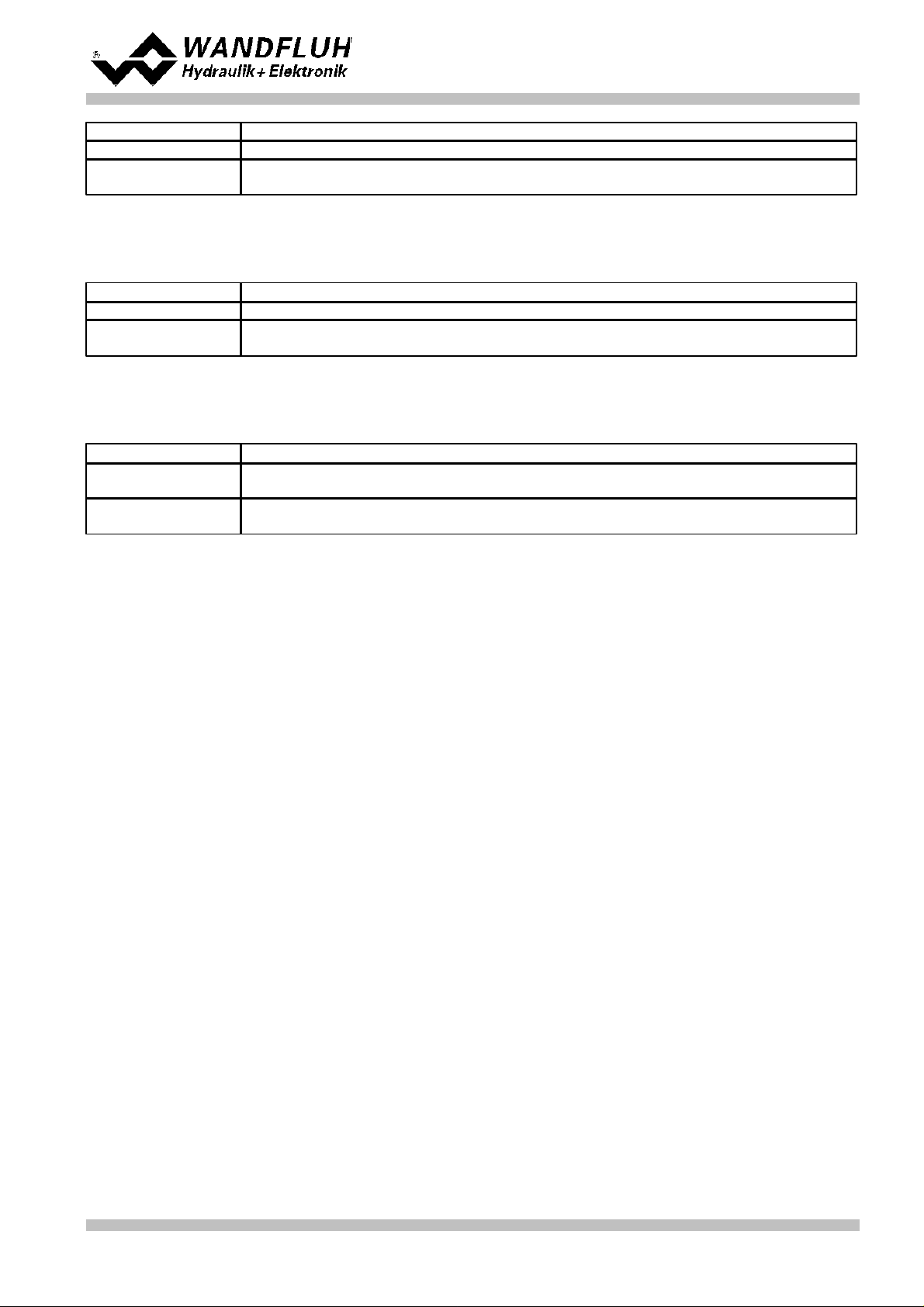
Selection
Here one can choose what error should activate the selected digital output
Dig. output
As soon as one of the selected error occurs, the selected digital output will be activated
Error action
With error "Cablebreak command signal" and "Cablebreak feedback signal", the desired
error action can be set. The default setting is "Solenoid 1 + 2 off"
8.13 Set function (optional)
Parameter
Description
Selection
Here one can choose what function should activate the selected digital output
Dig. output
As soon as one of the selected functions occurs, the selected digital output will be
activated
Parameter
Description
Enable
Selection, if the channel is constantly enabled (selection "on"), constantly disabled
(selection "off") of if it depends on a digital input (selection "external")
Dig. input
If the parameter "Enable" is set to *external", the corresponding digital input can be
selected here (in the example "DigInp1")
8.14 Set enable channel
Step by Step Instruction for Controller Electronics DSV
Wandfluh AG
Postfach
CH-3714 Frutigen
Tel: +41 33 672 72 72
Fax: +41 33 672 72 12
Email: sales@wandfluh.com
Internet: www.wandfluh.com
Page 56
Edition 09 13
DSV_StepByStep_d.pdf
Page 57

Step by Step Instruction for Controller Electronics DSV
8.15 Save parameters in a file (optional)
Select "File - Save as ..."
Enter the directory and file name, afterwards select "OK"
If required, enter the corresponding values to "Operator" and "Remarks", afterwards select "OK"
In the header line the corresponding file name appears
Wandfluh AG
Postfach
CH-3714 Frutigen
Tel: +41 33 672 72 72
Fax: +41 33 672 72 12
Email: sales@wandfluh.com
Internet: www.wandfluh.com
Page 57
Edition 09 13
DSV_StepByStep_d.pdf
Page 58

Step by Step Instruction for Controller Electronics DSV
8.16 Activate PASO On Line mode
Select "File - Activate On Line"
Select "Program the Wandfluh-Electronic with the new actual data?"
Select "OK"
Select "send all parameters without the valve specific parameters"
Select "OK"
Wait, until all parameters are sent to the DSV Electronics
In the status line the message "On-Line" appears
Wandfluh AG
Postfach
CH-3714 Frutigen
Tel: +41 33 672 72 72
Fax: +41 33 672 72 12
Email: sales@wandfluh.com
Internet: www.wandfluh.com
Page 58
Edition 09 13
DSV_StepByStep_d.pdf
Page 59

Step by Step Instruction for Controller Electronics DSV
Controller mode:
2-point controller (2-sol)
Command signal:
0 ... 10V on analog input 1
Feedback signal:
0 ... 10V on analog input 3
max. working stroke:
0 ... 50°C
desired working
stroke:
0 ... 50°C
Control behavior:
oil temperature < command temperature = oil to p
oil temperature >= command temperature = oil via cooler to tank, simultaneously switch
on the cooling circuit
Valve connection:
solenoid A = 3/2-way switching valve to switch oil to p - oil via cooler to tank
solenoid B = 2/2-way switching valve for switch on the cooling circuit
Enable channel:
external via digital input 1
9
Setup Instruction 2-point controller (2-sol)
9.1 Introduction
This guide shows with an example how to set channel 1 of the DSV Electronics as a 2-point controller
(2-solenoid).
Pretended:
Wandfluh AG
Postfach
CH-3714 Frutigen
Tel: +41 33 672 72 72
Fax: +41 33 672 72 12
Email: sales@wandfluh.com
Internet: www.wandfluh.com
Page 59
Edition 09 13
DSV_StepByStep_d.pdf
Page 60

Step by Step Instruction for Controller Electronics DSV
1.
Activate PASO Off Line mode
2.
Select controller mode
3.
Select valve type
4.
Scale command signal
5.
Scale feedback signal
6.
Set command values fixed (optional)
7.
Set command generator
8.
Set windows
9.
Set controller
10.
Set solenoid driver 1
11.
Set solenoid driver 2
12.
Set error evaluation (optional)
13.
Set function (optional)
14.
Set enable channel
15.
Save parameters in a file (optional)
16.
Activate PASO On Line mode
17.
By activating the digital input 1, the channel 1 will be released in the controller mode "2-point controller
(2-sol)"
The following steps are necessary (steps with the remark "optional" are only necessary if needed):
61
61
61
61
62
62
62
62
63
63
64
64
64
64
65
66
Wandfluh AG
Postfach
CH-3714 Frutigen
Tel: +41 33 672 72 72
Fax: +41 33 672 72 12
Email: sales@wandfluh.com
Internet: www.wandfluh.com
DSV_StepByStep_d.pdf
Page 60
Edition 09 13
Page 61

9.2 Activate PASO Off Line mode
Parameter
Description
Controller mode
Select controller mode "2-point controller (2-sol)"
Displayed unit
Select the desired unit (in the example "Free unit" and "°C")
Parameter
Description
Solenoid type
Select the solenoid type of the connected valve (in the example "Proportional solenoid
with current measurement")
Valve type
Select the valve type of the connected valve (in the example "Standard 2-solenoid")
Parameter
Description
Signal type
Set the signal type from the command signal generator (in the example "Voltage")
Used analog input
If the parameter "Signal type" is set to "Voltage" or "Current", the input where the
command signal generator is connect can be selected here (in the example "AnaInp1
[V]")
Used digital input
If the parameter "Signal type" is set to "Digital", "Frequency" or "PWM", the input where
the command signal generator is connect can be selected here
Cablebreak
detection
If the parameter "Signal type" is set to "Current", "Frequency" or "PWM", a cablebreak
detection of the command signal generator can be activated
Lower cablebreak
limit
If the parameter "Cablebreak detection" is set to "yes", the lower limit of this detection
can be set here
(command value < lower cablebreak limit = cablebreak)
Upper cablebreak
limit
If the parameter "Cablebreak detection" is set to "yes", the upper limit of this detection
can be set here
(command value > upper cablebreak limit = cablebreak)
Select "File - Activate Off Line"
Select "OK"
In the status line the message "Off-Line" appears
Step by Step Instruction for Controller Electronics DSV
9.3 Select controller mode
All other parameters in this window will be set later.
9.4 Select valve type
The remaining parameters have no function in this control mode
9.5 Scale command signal
Wandfluh AG
Postfach
CH-3714 Frutigen
Tel: +41 33 672 72 72
Fax: +41 33 672 72 12
Email: sales@wandfluh.com
Internet: www.wandfluh.com
Page 61
Edition 09 13
DSV_StepByStep_d.pdf
Page 62

Step by Step Instruction for Controller Electronics DSV
min interface
Set the minimum command signal level (in the example 0V)
max interface
Set the maximum command signal level (in the example 10V)
min reference
Set the minimum desired temperature (correspond to the temperature at "min interface",
in the example 0°C)
max reference
Set the maximum desired temperature (correspond to the temperature at "max
interface", in the example 50°C)
Parameter
Description
Signal type
Set the signal type from the feedback signal generator (in the example "Voltage")
Used analog input
If the parameter "Signal type" is set to "Voltage" or "Current", the input where the
feedback signal generator is connect can be selected here (in the example "AnaInp2
[V]")
Used digital input
If the parameter "Signal type" is set to "Digital", "Frequency" or "PWM", the input where
the feedback signal generator is connect can be selected here
Cablebreak
detection
If the parameter "Signal type" is set to "Current", "Frequency" or "PWM", a cablebreak
detection of the feedback signal generator can be activated
Lower cablebreak
limit
If the parameter "Cablebreak detection" is set to "yes", the lower limit of this detection
can be set here
(feedback value < lower cablebreak limit = cablebreak)
Upper cablebreak
limit
If the parameter "Cablebreak detection" is set to "yes", the upper limit of this detection
can be set here
(feedback value > upper cablebreak limit = cablebreak)
min interface
Set the minimum feedback signal level
(correspond to the feedback signal level at "min reference", in the example 0V)
max interface
Set the maximum feedback signal level
(correspond to the feedback signal level at "max reference", in the example 10V)
min reference
Set the minimum possible temperature (in the example 0°C)
max reference
Set the maximum possible temperature (in the example 50°C)
Parameter
Description
Enable
Enable the fixed command value function
Selection 1
Set the desired digital input for the fixed command value 1
Fixed command
value 1
Set the desired command value for the fixed command value 1. This value becomes the
active command value if the digital from "Selection 1" is activated
Parameter
Description
Speed +
This will set the temperature rise speed of the system
(temperature rise = positive control deviation => command > feedback)
Speed -
This will set the temperature reducing speed of the system
(temperature reducing = negative control deviation => command < feedback)
Parameter
Description
Target window type
Switch on/off the target window function
Target window threshold
Defines the target window range
(control deviation < target window threshold = target window reached)
Target window delay time
Delay time when falling below and exceeding the target window threshold
The remaining parameters have no function in this control mode
9.6 Scale feedback signal
9.7 Set command values fixed (optional)
9.8 Set speed (optional)
9.9 Set windows
Wandfluh AG
Postfach
CH-3714 Frutigen
Tel: +41 33 672 72 72
Fax: +41 33 672 72 12
Email: sales@wandfluh.com
Internet: www.wandfluh.com
Page 62
Edition 09 13
DSV_StepByStep_d.pdf
Page 63

Trailing window type
Switch on/off the trailing window function
ATTENTION: With "on with error", the solenoid outputs will be disabled as
soon as the trailing window is active!
Trailing window threshold
Defines the trailing window range
(control deviation < trailing window threshold = trailing window reached)
Trailing window delay time
Delay time when falling below and exceeding the trailing window threshold
Solenoid-Off window type
Switch on/off the Solenoid-Off window function
Solenoid-Off window
threshold
Defines the Solenoid-Off window range
(control deviation < Solenoid-Off window threshold = solenoid are blocked)
Solenoid-Off window delay
time
Delay time when falling below and exceeding the Solenoid-Off window threshold
9.10 Set controller
Parameter
Description
Command feed
forward
In this control mode, this parameter must be set to 0
Velocity feed forward
In this control mode, this parameter must be set to 0
Parameter
Description
Threshold 1
Control deviation, at which the solenoid output from solenoid driver 1 and solenoid
driver 2 will be set to 100%
(with increasing control deviation)
Threshold 2
Control deviation, at which the solenoid output from solenoid driver 1 and solenoid
driver 1 will be set to 0%
(with decreasing control deviation)
Parameter
Description
Solenoid output
Select the output, where the solenoid for switch oil to p - oil via cooler to tank is
connected
(in the example "SolOutA")
Enable
Selection, if the solenoid output is constantly enabled (selection "on"), constantly
disabled (selection "off") or if it depends on a digital input (selection "external")
Dig. input
If the parameter "Enable" is set to "external", the corresponding digital input can be
selected here
Inversion
If a solenoid with a inverse function is used, this selection should be "yes", otherwise
"no"
Cablebreak
detection
If the cablebreak detection for the solenoid output is desired, this selection should be
"yes", otherwise "no"
Characteristic
optimisation
the characteristic optimisation is desired, this selection should be "yes", otherwise "no".
(the settings for the characteristic optimisation is made in the Tab-window
"Characteristic optimisation")
Reduction time
If a power reduction on the solenoid output is desired, the time after the reduction will
start can be set here. With a setting from "0ms", the power reduction is switched off.
Reduced value
If a power reduction on the solenoid output is desired, the value where the output will be
reduced to can be set here. With a setting from "100%", the reduction is switched off.
General
Step by Step Instruction for Controller Electronics DSV
n-point controller
9.11 Set solenoid driver 1
The remaining parameters have no function in this control mode
Wandfluh AG
Postfach
CH-3714 Frutigen
Tel: +41 33 672 72 72
Fax: +41 33 672 72 12
Email: sales@wandfluh.com
Internet: www.wandfluh.com
Page 63
Edition 09 13
DSV_StepByStep_d.pdf
Page 64
Step by Step Instruction for Controller Electronics DSV
Parameter
Description
Solenoid output
Select the output, where the solenoid for the cooling system is connected (in the
example "SolOutB")
Enable
Selection, if the solenoid output is constantly enabled (selection "on"), constantly
disabled (selection "off") or if it depends on a digital input (selection "external")
Dig. input
If the parameter "Enable" is set to "external", the corresponding digital input can be
selected here
Inversion
If a solenoid with a inverse function is used, this selection should be "yes", otherwise
"no"
Cablebreak
detection
If the cablebreak detection for the solenoid output is desired, this selection should be
"yes", otherwise "no"
Characteristic
optimisation
the characteristic optimisation is desired, this selection should be "yes", otherwise "no".
(the settings for the characteristic optimisation is made in the Tab-window
"Characteristic optimisation")
Reduction time
If a power reduction on the solenoid output is desired, the time after the reduction will
start can be set here. With a setting from "0ms", the power reduction is switched off.
Reduced value
If a power reduction on the solenoid output is desired, the value where the output will be
reduced to can be set here. With a setting from "100%", the reduction is switched off.
Parameter
Description
Selection
Here one can choose what error should activate the selected digital output
Dig. output
As soon as one of the selected error occurs, the selected digital output will be activated
Error action
With error "Cablebreak command signal" and "Cablebreak feedback signal", the desired
error action can be set. The default setting is "Solenoid 1 + 2 off"
Parameter
Description
Selection
Here one can choose what function should activate the selected digital output
Dig. output
As soon as one of the selected functions occurs, the selected digital output will be
activated
Parameter
Description
Enable
Selection, if the channel is constantly enabled (selection "on"), constantly disabled
(selection "off") of if it depends on a digital input (selection "external")
Dig. input
If the parameter "Enable" is set to *external", the corresponding digital input can be
selected here (in the example "DigInp1")
9.12 Set solenoid driver 2
The remaining parameters have no function in this control mode
9.13 Set error evaluation (optional)
9.14 Set function (optional)
9.15 Set enable channel
Wandfluh AG
Postfach
CH-3714 Frutigen
Tel: +41 33 672 72 72
Fax: +41 33 672 72 12
Email: sales@wandfluh.com
Internet: www.wandfluh.com
Page 64
Edition 09 13
DSV_StepByStep_d.pdf
Page 65

Step by Step Instruction for Controller Electronics DSV
9.16 Save parameters in a file (optional)
Select "File - Save as ..."
Enter the directory and file name, afterwards select "OK"
If required, enter the corresponding values to "Operator" and "Remarks", afterwards select "OK"
In the header line the corresponding file name appears
Wandfluh AG
Postfach
CH-3714 Frutigen
Tel: +41 33 672 72 72
Fax: +41 33 672 72 12
Email: sales@wandfluh.com
Internet: www.wandfluh.com
Page 65
Edition 09 13
DSV_StepByStep_d.pdf
Page 66

Step by Step Instruction for Controller Electronics DSV
9.17 Activate PASO On Line mode
Select "File - Activate On Line"
Select "Program the Wandfluh-Electronic with the new actual data?"
Select "OK"
Select "send all parameters without the valve specific parameters"
Select "OK"
Wait, until all parameters are sent to the DSV Electronics
In the status line the message "On-Line" appears
Wandfluh AG
Postfach
CH-3714 Frutigen
Tel: +41 33 672 72 72
Fax: +41 33 672 72 12
Email: sales@wandfluh.com
Internet: www.wandfluh.com
Page 66
Edition 09 13
DSV_StepByStep_d.pdf
Page 67
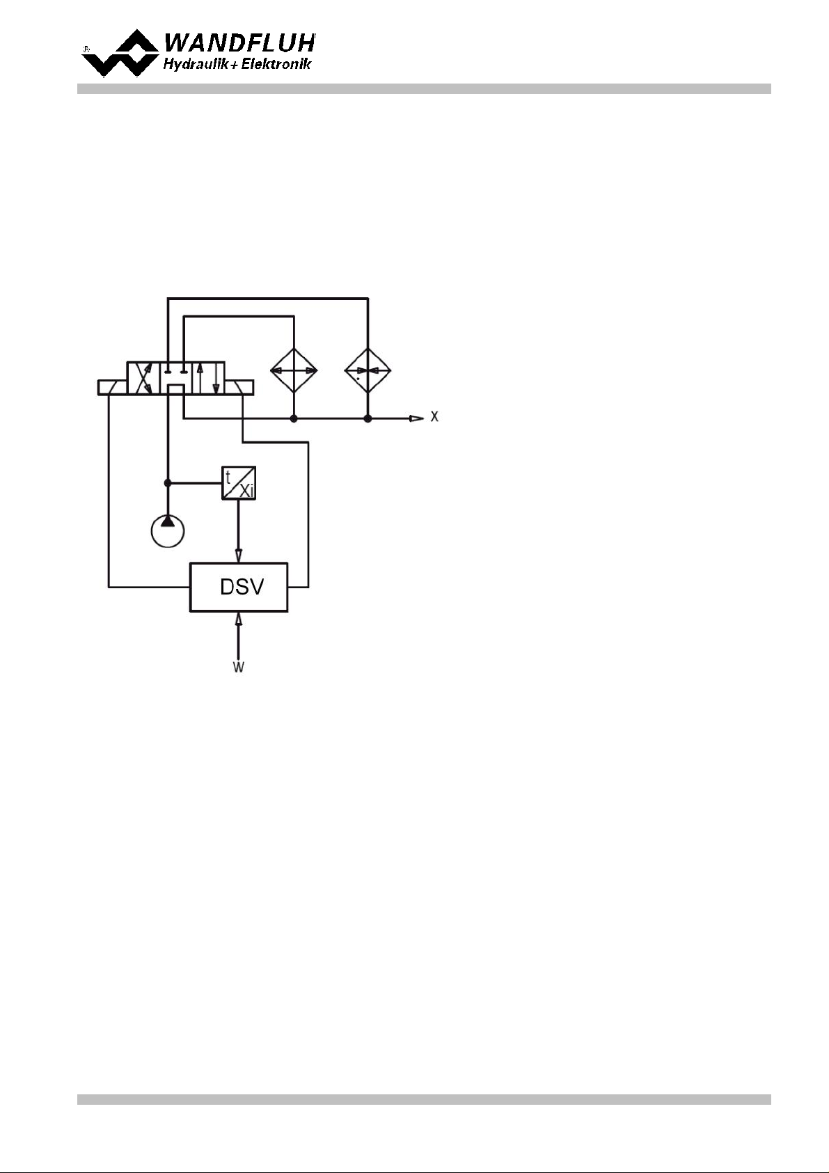
Step by Step Instruction for Controller Electronics DSV
Controller mode:
3-point controller (2-sol)
Command signal:
0 ... 10V on analog input 1
Feedback signal:
0 ... 20mA on analog input 3
max. working stroke:
0 ... 50°C
desired working
stroke:
0 ... 50°C
Control behavior:
oil temperature < command temperature - 5°C = oil via heating to x
oil temperature > command temperature + 5°C = oil via cooler to x
otherwise oil direct to x
Valve connection:
4/3-way switching valve, solenoid A for heating, solenoid B for cooling
Enable channel:
external via digital input 1
10
Setup Instruction 3-point controller (2-sol)
10.1 Introduction
This guide shows with an example how to set channel 1 of the DSV Electronics as a 3-point controller
(2-solenoid).
Pretended:
Wandfluh AG
Postfach
CH-3714 Frutigen
Tel: +41 33 672 72 72
Fax: +41 33 672 72 12
Email: sales@wandfluh.com
Internet: www.wandfluh.com
Page 67
Edition 09 13
DSV_StepByStep_d.pdf
Page 68
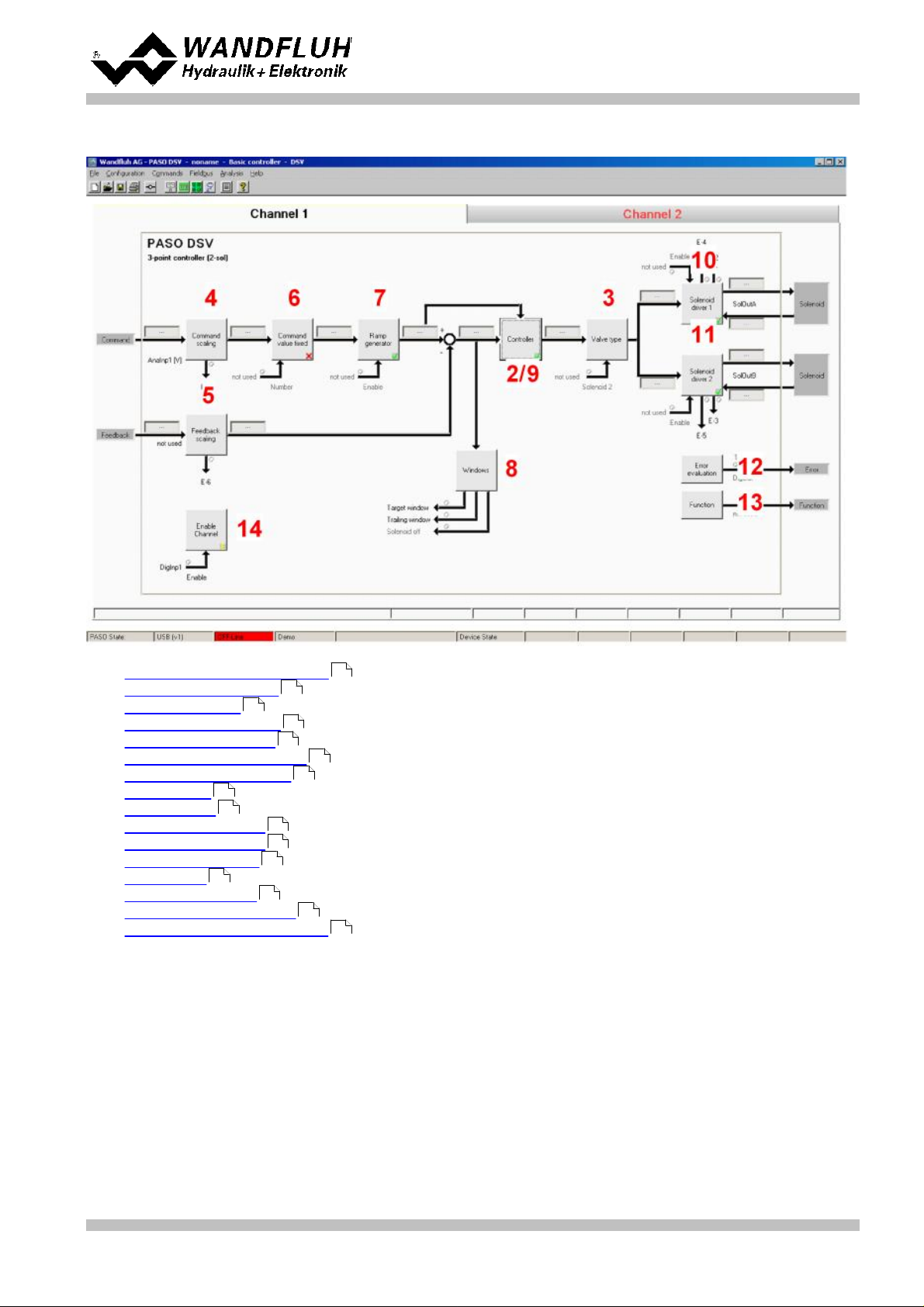
Step by Step Instruction for Controller Electronics DSV
1.
Activate PASO Off Line mode
2.
Select controller mode
3.
Select valve type
4.
Scale command signal
5.
Scale feedback signal
6.
Set command values fixed (optional)
7.
Set command generator
8.
Set windows
9.
Set controller
10.
Set solenoid driver 1
11.
Set solenoid driver 2
12.
Set error evaluation (optional)
13.
Set function (optional)
14.
Set enable channel
15.
Save parameters in a file (optional)
16.
Activate PASO On Line mode
17.
By activating the digital input 1, the channel 1 will be released in the controller mode "3-point controller
(2-sol)"
The following steps are necessary (steps with the remark "optional" are only necessary if needed):
69
69
69
69
70
70
70
70
71
71
72
72
72
72
73
74
Wandfluh AG
Postfach
CH-3714 Frutigen
Tel: +41 33 672 72 72
Fax: +41 33 672 72 12
Email: sales@wandfluh.com
Internet: www.wandfluh.com
DSV_StepByStep_d.pdf
Page 68
Edition 09 13
Page 69
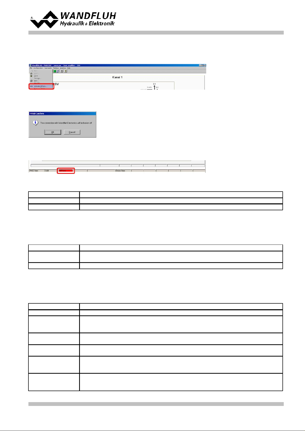
10.2 Activate PASO Off Line mode
Parameter
Description
Controller mode
Select controller mode "3-point controller (2-sol)"
Displayed unit
Select the desired unit (in the example"Free unit" and "°C")
Parameter
Description
Solenoid type
Select the solenoid type of the connected valve (in the example "Proportional solenoid
with current measurement")
Valve type
Select the valve type of the connected valve (in the example "Standard 2-solenoid")
Parameter
Description
Signal type
Set the signal type from the command signal generator (in the example "Voltage")
Used analog input
If the parameter "Signal type" is set to "Voltage" or "Current", the input where the
command signal generator is connect can be selected here (in the example "AnaInp1
[V]")
Used digital input
If the parameter "Signal type" is set to "Digital", "Frequency" or "PWM", the input where
the command signal generator is connect can be selected here
Cablebreak
detection
If the parameter "Signal type" is set to "Current", "Frequency" or "PWM", a cablebreak
detection of the command signal generator can be activated
Lower cablebreak
limit
If the parameter "Cablebreak detection" is set to "yes", the lower limit of this detection
can be set here
(command value < lower cablebreak limit = cablebreak)
Upper cablebreak
limit
If the parameter "Cablebreak detection" is set to "yes", the upper limit of this detection
can be set here
(command value > upper cablebreak limit = cablebreak)
Select "File - Activate Off Line"
Select "OK"
In the status line the message "Off-Line" appears
Step by Step Instruction for Controller Electronics DSV
10.3 Select controller mode
All other parameters in this window will be set later.
10.4 Select valve type
The remaining parameters have no function in this control mode
10.5 Scale command signal
Wandfluh AG
Postfach
CH-3714 Frutigen
Tel: +41 33 672 72 72
Fax: +41 33 672 72 12
Email: sales@wandfluh.com
Internet: www.wandfluh.com
Page 69
Edition 09 13
DSV_StepByStep_d.pdf
Page 70

Step by Step Instruction for Controller Electronics DSV
min interface
Set the minimum command signal level (in the example 0V)
max interface
Set the maximum command signal level (in the example 10V)
min reference
Set the minimum desired temperature (correspond to the temperature at "min interface",
in the example 0°C)
max reference
Set the maximum desired temperature (correspond to the temperature at "max
interface", in the example 50°C)
Parameter
Description
Signal type
Set the signal type from the feedback signal generator (in the example "Voltage")
Used analog input
If the parameter "Signal type" is set to "Voltage" or "Current", the input where the
feedback signal generator is connect can be selected here (in the example "AnaInp2
[V]")
Used digital input
If the parameter "Signal type" is set to "Digital", "Frequency" or "PWM", the input where
the feedback signal generator is connect can be selected here
Cablebreak
detection
If the parameter "Signal type" is set to "Current", "Frequency" or "PWM", a cablebreak
detection of the feedback signal generator can be activated
Lower cablebreak
limit
If the parameter "Cablebreak detection" is set to "yes", the lower limit of this detection
can be set here
(feedback value < lower cablebreak limit = cablebreak)
Upper cablebreak
limit
If the parameter "Cablebreak detection" is set to "yes", the upper limit of this detection
can be set here
(feedback value > upper cablebreak limit = cablebreak)
min interface
Set the minimum feedback signal level
(correspond to the feedback signal level at "min reference", in the example 0V)
max interface
Set the maximum feedback signal level
(correspond to the feedback signal level at "max reference", in the example 10V)
min reference
Set the minimum possible temperature (in the example 0°C)
max reference
Set the maximum possible temperature (in the example 50°C)
Parameter
Description
Enable
Enable the fixed command value function
Selection 1
Set the desired digital input for the fixed command value 1
Fixed command
value 1
Set the desired command value for the fixed command value 1. This value becomes the
active command value if the digital from "Selection 1" is activated
Parameter
Description
Speed +
This will set the temperature rise speed of the system
(temperature rise = positive control deviation => command > feedback)
Speed -
This will set the temperature reducing speed of the system
(temperature reducing = negative control deviation => command < feedback)
Parameter
Description
Target window type
Switch on/off the target window function
Target window threshold
Defines the target window range
(control deviation < target window threshold = target window reached)
Target window delay time
Delay time when falling below and exceeding the target window threshold
The remaining parameters have no function in this control mode
10.6 Scale feedback signal
10.7 Set command values fixed (optional)
10.8 Set speed (optional)
10.9 Set windows
Wandfluh AG
Postfach
CH-3714 Frutigen
Tel: +41 33 672 72 72
Fax: +41 33 672 72 12
Email: sales@wandfluh.com
Internet: www.wandfluh.com
Page 70
Edition 09 13
DSV_StepByStep_d.pdf
Page 71
Trailing window type
Switch on/off the trailing window function
ATTENTION: With "on with error", the solenoid outputs will be disabled as
soon as the trailing window is active!
Trailing window threshold
Defines the trailing window range
(control deviation < trailing window threshold = trailing window reached)
Trailing window delay time
Delay time when falling below and exceeding the trailing window threshold
Solenoid-Off window type
Switch on/off the Solenoid-Off window function
Solenoid-Off window
threshold
Defines the Solenoid-Off window range
(control deviation < Solenoid-Off window threshold = solenoid are blocked)
Solenoid-Off window delay
time
Delay time when falling below and exceeding the Solenoid-Off window threshold
10.10 Set controller
Parameter
Description
Command feed
forward
In this control mode, this parameter must be set to 0
Velocity feed forward
In this control mode, this parameter must be set to 0
Parameter
Description
Threshold 1
Control deviation, at which the solenoid output from solenoid driver 1 will be set to
100%
(with increasing control deviation)
Threshold 2
Control deviation, at which the solenoid output from solenoid driver 1 will be set to 0%
(with decreasing control deviation)
Threshold 3
Control deviation, at which the solenoid output from solenoid driver 2 will be set to
100%
(with decreasing control deviation)
Threshold 4
Control deviation, at which the solenoid output from solenoid driver 2 will be set to 0%
(with increasing control deviation)
Parameter
Description
Solenoid output
Select the output, where the solenoid for cooling is heating (in the example "SolOutA")
Enable
Selection, if the solenoid output is constantly enabled (selection "on"), constantly
disabled (selection "off") or if it depends on a digital input (selection "external")
Dig. input
If the parameter "Enable" is set to "external", the corresponding digital input can be
selected here
Inversion
If a solenoid with a inverse function is used, this selection should be "yes", otherwise
"no"
Cablebreak
detection
If the cablebreak detection for the solenoid output is desired, this selection should be
"yes", otherwise "no"
Characteristic
optimisation
If the characteristic optimisation is desired, this selection should be "yes", otherwise
"no".
(the settings for the characteristic optimisation is made in the Tab-window
"Characteristic optimisation")
Reduction time
If a power reduction on the solenoid output is desired, the time after the reduction will
start can be set here. With a setting from "0ms", the power reduction is switched off.
Reduced value
If a power reduction on the solenoid output is desired, the value where the output will be
reduced to can be set here. With a setting from "100%", the reduction is switched off.
General
Step by Step Instruction for Controller Electronics DSV
n-point controller
10.11 Set solenoid driver 1
The remaining parameters have no function in this control mode
Wandfluh AG
Postfach
CH-3714 Frutigen
Tel: +41 33 672 72 72
Fax: +41 33 672 72 12
Email: sales@wandfluh.com
Internet: www.wandfluh.com
Page 71
Edition 09 13
DSV_StepByStep_d.pdf
Page 72

10.12 Set solenoid driver 2
Parameter
Description
Solenoid output
Select the output, where the solenoid for cooling is connected (in the example
"SolOutB")
Enable
Selection, if the solenoid output is constantly enabled (selection "on"), constantly
disabled (selection "off") or if it depends on a digital input (selection "external")
Dig. input
If the parameter "Enable" is set to "external", the corresponding digital input can be
selected here
Inversion
If a solenoid with a inverse function is used, this selection should be "yes", otherwise
"no"
Cablebreak
detection
If the cablebreak detection for the solenoid output is desired, this selection should be
"yes", otherwise "no"
Characteristic
optimisation
If the characteristic optimisation is desired, this selection should be "yes", otherwise
"no".
(the settings for the characteristic optimisation is made in the Tab-window
"Characteristic optimisation")
Reduction time
If a power reduction on the solenoid output is desired, the time after the reduction will
start can be set here. With a setting from "0ms", the power reduction is switched off.
Reduced value
If a power reduction on the solenoid output is desired, the value where the output will be
reduced to can be set here. With a setting from "100%", the reduction is switched off.
Parameter
Description
Selection
Here one can choose what error should activate the selected digital output
Dig. output
As soon as one of the selected error occurs, the selected digital output will be activated
Error action
With error "Cablebreak command signal" and "Cablebreak feedback signal", the desired
error action can be set. The default setting is "Solenoid 1 + 2 off"
Parameter
Description
Selection
Here one can choose what function should activate the selected digital output
Dig. output
As soon as one of the selected functions occurs, the selected digital output will be
activated
Parameter
Description
Enable
Selection, if the channel is constantly enabled (selection "on"), constantly disabled
(selection "off") of if it depends on a digital input (selection "external")
Dig. input
If the parameter "Enable" is set to *external", the corresponding digital input can be
selected here (in the example "DigInp1")
Step by Step Instruction for Controller Electronics DSV
The remaining parameters have no function in this control mode
10.13 Set error evaluation (optional)
10.14 Set function (optional)
10.15 Set enable channel
Wandfluh AG
Postfach
CH-3714 Frutigen
Tel: +41 33 672 72 72
Fax: +41 33 672 72 12
Email: sales@wandfluh.com
Internet: www.wandfluh.com
Page 72
Edition 09 13
DSV_StepByStep_d.pdf
Page 73

Step by Step Instruction for Controller Electronics DSV
10.16 Save parameters in a file (optional)
Select "File - Save as ..."
Enter the directory and file name, afterwards select "OK"
If required, enter the corresponding values to "Operator" and "Remarks", afterwards select "OK"
In the header line the corresponding file name appears
Wandfluh AG
Postfach
CH-3714 Frutigen
Tel: +41 33 672 72 72
Fax: +41 33 672 72 12
Email: sales@wandfluh.com
Internet: www.wandfluh.com
Page 73
Edition 09 13
DSV_StepByStep_d.pdf
Page 74

Step by Step Instruction for Controller Electronics DSV
10.17 Activate PASO On Line mode
Select "File - Activate On Line"
Select "Program the Wandfluh-Electronic with the new actual data?"
Select "OK"
Select "send all parameters without the valve specific parameters"
Select "OK"
Wait, until all parameters are sent to the DSV Electronics
In the status line the message "On-Line" appears
Wandfluh AG
Postfach
CH-3714 Frutigen
Tel: +41 33 672 72 72
Fax: +41 33 672 72 12
Email: sales@wandfluh.com
Internet: www.wandfluh.com
Page 74
Edition 09 13
DSV_StepByStep_d.pdf
 Loading...