

LENGA
Installation, Servicing and User instructions
500 - 800 | Front, Bay and Corner
EN
v.1.0-112016
This appliance has been tested and certied for other counties (see technical data). However to install
appliance in other countries, modication of the appliance and its method of installation may be
necessary in order to use the appliance safely and correctly. The manual for the local language must be
obtained. Contact Wanders for further information.
2
© Copyright 2016 Wanders res & stoves
The information contained herein is subject to change without notice. Wanders res & stoves shall not be liable for technical or editorial errors or omissions contained herein.
1. General Notes 3
2. User instructions 4
2.1 First Time of Operation 4
2.2 Remote control 4
2.3 Wanders Eco Wave App control (optional) 4
2.4 Cleaning and Maintenance 4
3. Installation instructions. 4
3.1 Gas Connection 4
3.2 Ventilation 4
3.3 Appliance Fireplace Installation 4
3.3.1 Building the Fireplace 5
3.3.2 Built-In Fireplace Sizing 5
3.3.3 Mantel Clearances 6
3.4 Flue Connection 8
3.4.1. General Notes 8
3.4.2 Timber Frame Construction 8
3.4.3 Carport or Building Extension 8
3.4.4 Basements, Lightwells and Retaining walls 8
3.4.5 Terminal Locations 9
3.4.6 Horizontal Wall Vent Termination type C11 10
3.4.7 Vertical Roof Vent Termination type C31 10
3.4.8 Flue restrictors to be tted 10
3.4.9 Typical installations 11
3.5 Fuel Bed Media and Arrangements 12
Lenga 500 12
Lenga 800 17
3.6 Commissioning the Appliance 24
3.6.1 Pilot Ignition Check 24
3.6.2 Main Burner Check 24
3.6.3 Pressure Check 24
4. Servicing 24
4.1 Cleaning the Ceramics 25
4.2 Servicing the Burners 25
4.3 Opening the Glass 25
Terugplaatsen van de glasruit 25
5. Technical Information 26
5.1 Countries of use 26
5.2 Technical Data 27
5.2.1 Lenga 500 27
5.2.2. Lenga 800 27
5.3 Dimensions 28
5.3.1.a Lenga 500 A 28
5.3.1.b Lenga 500 AB 28
5.3.1.c Lenga 500 AE 29
5.3.1.d Lenga 500 ABE 29
5.3.2.a Lenga 800 A 30
5.3.2.b Lenga 800 AB 30
5.3.2.c Lenga 800 AE 31
5.3.2.d Lenga 800 ABE 31
Electrical diagram 32

3
Installation, Servicing and User Instructions | EN
1. General Notes
• This Wanders gas appliance is a High Eciency, Balanced Flue Live Fuel Eect appliance. It provides radiant
and convected heat using the latest burner technology. As well as having a variable heat output, these res
also utilise a special control system that allows the appliance to use two burners for high output or a single
burner for lower outputs.
• One of the burners will be designated as the “Main” Burner, this is the Front, the second burner will be
designated as the “Eect” Burner. The Eect burner can be switched ON or OFF whilst the appliance is alight.
• Before Installation, check that the local distribution conditions, nature of the gas and pressure, and adjustment
of the appliance are compatible.
• This appliance is intended for use on a gas installation with a governed meter.
• This Gas Installation may only be installed by a registered professional competent person (Gas Safe installer in
the UK). The installation must adhere to the requirements of the local and national Building regulations and
national standards. The installation manual must also be followed.
• Ensure that the Flue Terminal is not in any way obstructed and is clear of vegetation, i.e. trees, shrubs etc. and
that no objects are leant against the terminal or guard.
• Always clean the Window Panel before the re is ignited. Any nger prints must be removed, as these will be
burnt into the glass and will be un-removable.
• Do not operate this appliance if the glass panel has been broken (or cracked), removed or is open.
• The appliance is designed to t numerous installation situations as listed in these installation instructions.
However only ue approved by Wanders for this appliance may be used.
• This appliance is a balanced ue product and is room sealed and as such requires no additional ventilation for
operation. However an adequate supply of fresh air to maintain temperatures and a comfortable environment
is recommended.
• This appliance is designed as a heating appliance, and as such will get very hot in operation; all surfaces (except
the controls and access door) are considered to be working surfaces and as such should not be touched. The
front windows and surrounds are not considered to be fully secure guards against accidental contact. It is
recommended that an approved re screen be used if children, the elderly or persons with limited mobility
are to be present in the same area.
• Do not place curtains, laundry, furniture etc. within a safe distance of 300mm of this appliance.
• Do not attempt to burn rubbish on this appliance.
• If this appliance is extinguished, on purpose or other, no attempt to relight should be made within 3 minutes.

4
2. User instructions
2.1 First Time of Operation
Before igniting the appliance, ensure that all packaging, safety stickers and any protective wrapping have been
removed, and that the glass has been cleaned, including all ngerprints from the glass.
Ensure that the room is adequately ventilated the rst time that the appliance is ignited; we would recommend
opening windows if possible. Run the appliance at full setting for a few hours so that the paint gets an opportunity
to fully cure. During this period it is possible for some fumes and vapours to be given o. We would recommend
keeping children and pets out of the area at this time.
2.2 Remote control
Please refer to the separately added manual for the SYMAX remote control system.
2.3 Wanders Eco Wave App control (optional)
Please refer to the separately added manual for the Wanders Eco Wave control system.
2.4 Cleaning and Maintenance
This appliance should be inspected and serviced once a year by a qualied, competent and registered person.
The inspection and maintenance must at least ensure that the appliance is working correctly and safely. It is
advisable to clean the appliance of any dust and debris before regularly during the heating season and especially
if the appliance has not been used for some time. This can be done with a soft brush and a vacuum cleaner or a
damp cloth and if required a non-abrasive cleaning agent. Do not use corrosive or abrasive substances to clean
the appliance.
3. Installation instructions.
Before commencing Installation, conrm that the details on the appliance data plate correspond to the local
distribution conditions, gas type and pressure to which the appliance is to be installed.
Ensure that gas supply and supply pipe is capable of delivering the required volume and pressure of gas and is in
accordance with the rules in force.
3.1 Gas Connection
This appliance has a gas inlet connection of Ø 8mm.
3.2 Ventilation
This appliance is a Balanced Flue room sealed appliance, and as such needs no additional ventilation. However an
adequate supply of fresh air to maintain temperatures and a comfortable environment is recommended.
This appliance may be installed in a completely sealed or mechanically ventilated house.
3.3 Appliance Fireplace Installation
• Determine the position required for the appliance.
• Create a gas connection for the appliance in approximately the correct location for the gas controls.
• The gas controls are connected to the Burner of the appliance. These controls need to be located in the
control access box, so an appropriate position for the access box needs to be determined.
• This appliance has fully adjustable legs, these must me set to the desired length before the ue position is
nalised. Fine adjustment of the legs is available via the feet.
• Do not make any adjustments to the appliance, except the leg length.
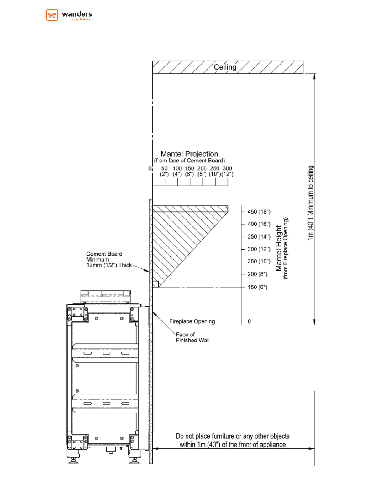
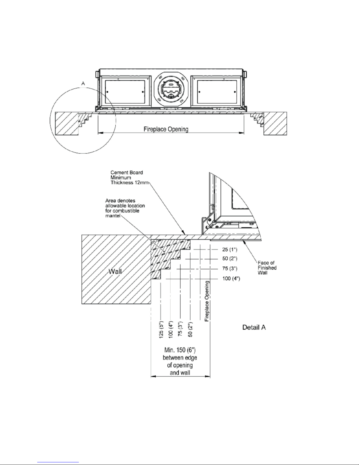
• The appliance should be tted with a minimum clearance of 150mm from any combustible objects or
materials; this includes any combustible materials used for the replace construction. This clearance distance
can be reduced to 50mm if a Cement Board, of minimum thickness 12mm is used. This Cement Board will act
as a Thermal Break.
• The clearance distance of the Flue from combustibles must not be less than 75mm. This dimension can be
reduced to 25mm as the distance from the underside and the sides of Horizontal Flue runs.
5
Installation, Servicing and User Instructions | EN
• As this is a room sealed appliance and the appliance stands on appropriate legs, a hearth is not required for
this appliance.
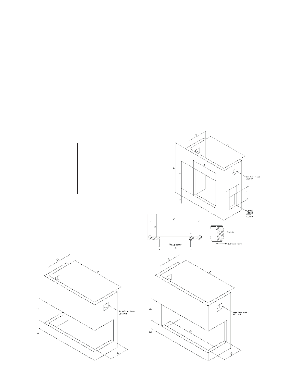
• The Fireplace should be ventilated with openings giving a total free vent area of 200 cm².
• A gap of 50mm should be left all round the appliance.
• If a shelf is to be tted above the replace opening, a gap of 150mm minimum should be left between the
opening and the shelf.See section 3.3.3, Mantel Clearances.
• The brackets supplied may be used for securing the appliance to a rear wall.
3.3.1 Building the Fireplace
• Construct a studwork replace to the desired sizes, minimum sizes are shown in section 3.3.2. Any combustible
material used to construct the Fireplace must not be closer than the minimum dimensions quoted in section
3.3 above. Cement Board of minimum thickness 12mm, can be used as a Thermal Break and can be used
directly against the Frame Face on the appliance.
• Do not use insulation material (or other) to pack the void around or above the appliance.
• Provide ventilation from the replace to the minimum amount quoted in 3.3 above.
• Provide a cut-out for the Control Access Door.
3.3.2 Built-In Fireplace Sizing
(assuming a Cement Board Lining is used)
Appliance
A
minB minC minD min
E
min
F
minG minH min
Lenga 500 A 552 905 655 415 195 1235 n/a n/a
Lenga 500 ABC n/a 905 600 415 195 1235 290 n/a
Lenga 500 AB/AC n/a 905 640 415 195 1235 290 505
Lenga 800 A 852 755 955 415 195 1083 n/a n/a
Lenga 800 ABC n/a 755 900 415 195 1083 290 n/a
Lenga 800 AB/AC n/a 755 940 415 195 1083 290 805
6
3.3.3 Mantel Clearances
3.3.3.a Combustible Mantel - side view
7
Installation, Servicing and User Instructions | EN
3.3.3.b Combustible Mantel/Side Wall - top view

8
3.4 Flue Connection
3.4.1. General Notes
This appliance may be installed with a roof terminal (C31) or a wall terminal (C11).
This appliance may only be used with Balanced Flue (otherwise known as Concentric Flue) parts as specied by
Wanders. The Wanders specied ue parts have been approved with the appliance. If the appliance is installed
on non-Wanders approved parts, Wanders cannot guarantee or accept and responsibility for the proper and safe
working of the appliance.
The ue system must be constructed from the appliance upwards, with all joints being fully locked and sealed
using the Wanders specied parts. Flue systems approved for this Appliance:
• Muelink & Grol (M&G) Concentric.
• Poujoulat PGI.
• Metaloterm US.
3.4.2 Timber Frame Construction
Whilst it is possible to install room-sealed appliances in timber frame properties, great care needs to be taken to
ensure that the ue assembly does not interfere with the weather proong qualities of any outer wall which it
may penetrate. Before attempting this work, further details need to be referenced, (e.g. “Gas Installations in Timber
Frame Buildings” from the CORGI installer series in the UK).
3.4.3 Carport or Building Extension
Where a ue terminal is sited within a carport or building extension, it should have at least two completely open
and unobstructed sides. The distance between the lowest part of the roof and the top of the terminal should be
at least 600mm.
Note: A covered passageway should not be treated as a carport. Flues should not be sited in a covered passageway
between properties.
3.4.4 Basements, Lightwells and Retaining walls
Flue terminals should not be sited within the connes of a basement area, light well or external space formed by a
retaining wall, unless steps are taken to ensure the products of combustion can disperse safely at all times. It may
be possible to install this Balanced Flue system in such a location provided that it is not sited lower than 1m from
the top level of that area to allow combustion products to disperse safely.
Flue terminals should be sited to ensure total clearance of the combustion products in accordance with the
included information.
When the products of combustion are discharged, they should not cause a nuisance to adjoining or adjacent
properties and they should be positioned so that damage cannot occur to other parts of the building. If the outer
wall surface is constructed of combustible material, a non-combustible plate should be tted behind the terminal
projecting 25mm beyond the external edges of the terminal.
9
Installation, Servicing and User Instructions | EN
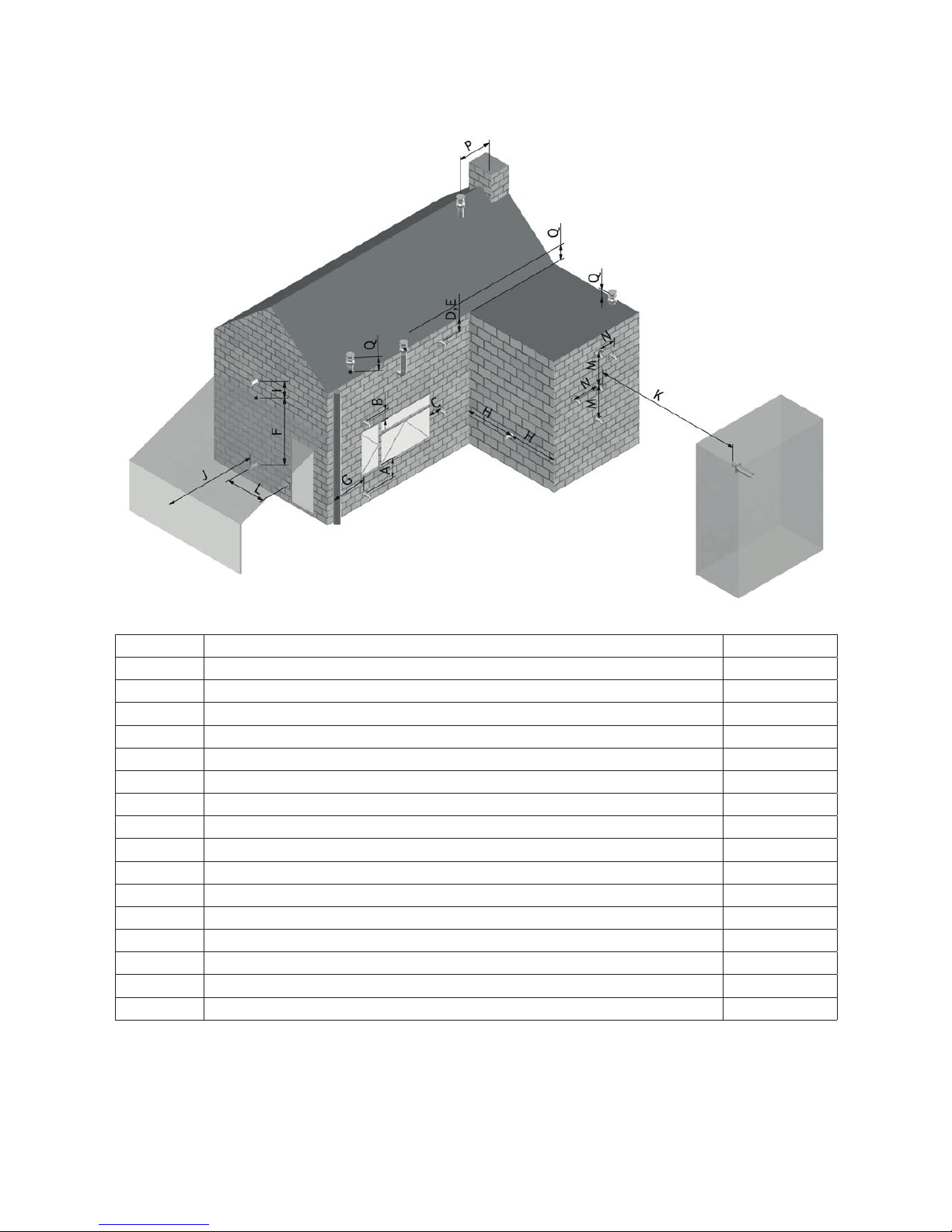
3.4.5 Terminal Locations
Dimension Terminal Position Distance (mm)
A* Directly below an opening, air brick, opening window etc. 600
B Above an opening, air brick, opening window etc. 300
C Adjacent to an opening, air brick, opening window etc. 400
D Below gutters, soil pipes or drain pipes 300
E Below eaves 300
F Below balconies or car port roof 600
G From a vertical drain pipe or soil pipe 300
H From an internal or external corner 600
I Above ground roof or balcony level 300
J From a surface facing the terminal 600
K From a terminal facing the terminal 600
L From an opening in the car port (e.g. door, window into the dwelling) 1200
M Vertically from a terminal on the same wall 1500
N Horizontally from a terminal on the same wall 300
P From a vertical structure on the roof 600
Q Above intersection with roof 150
* In addition, the terminal should not be nearer than 300mm to an opening in the building fabric
formed for the purpose of accommodating a built in element such as a window frame.
10
3.4.6 Horizontal Wall Vent Termination type C11
Flue sizing and regulations.
Lenga 500
• Ø100/150 Connector on appliance.
• Ø100/150 to be used throughout.
• Maximum horizontal length is 3 meters.
• Minimum vertical length directly on appliance is 1 meter.
• Maximum pipe extension for outside wall (H) is 2 x vertical pipe rise (V).
• Maximum length of the entire system (excl. outlet terminal) is 10 meters.
• Flue Terminal: Ø100/150 Part No. INK.4330
Lenga 800
• Ø130/200 Connector on appliance.
• Ø130/200 to be used throughout.
• Do NOT reduce to 100/150.
• Maximum horizontal length is 3 meters.
• Minimum vertical length directly on appliance is 1 meter.
• Maximum pipe extension for outside wall (H) is 4 x vertical pipe rise (V).
• Maximum length of the entire system (excl. outlet terminal) is 10 meters.
• Flue Terminal: Ø130/200 Part No. INK.4430
3.4.7 Vertical Roof Vent Termination type C31
Flue sizing and regulations.
Lenga 500
• Ø100/150 Connector on appliance.
• Ø100/150 to be used throughout.
• Maximum horizontal length is 3 meters.
• Minimum vertical length directly on appliance is 1 meter.
• Maximum length of the entire system (excl. outlet terminal) is 10 meters.
• Flue Terminal: Ø100/150 Part No. INK.4335
Lenga 800
• Ø130/200 Connector on appliance.
• Ø130/200 to be used throughout.
• Reducing to 100/150 is allowed if the ue run is entirely vertical with a maximum length of 10 meters. The rst
meter needs to be 130/200.
• Reducing to 100/150 is allowed when the ue run has elbows in it, but only at the very last moment just
before the roof outlet.
• Maximum horizontal length is 3 meters.
• Minimum vertical length directly on appliance is 1 meter.
• Maximum length of the entire system (excl. outlet terminal) is 10 meters.
• Reducer Ø130/200 > 100/150 Part No. INK.4490
• Flue Terminal: Ø100/150 Part No. INK.4430
3.4.8 Flue restrictors to be tted
The restrictor can be installed with the pre-installed M5x20 bolts
Lenga 500
Wall terminal:
• Ø100/150, vertical rise 1 meter, no restrictor
• Ø100/150, vertical rise > 1 meter, 35 mm restrictor
Roof terminal:
• Ø100/150, vertical rise < 2 meter, 35 mm restrictor
• Ø100/150, vertical rise > 2 meter, 60 mm restrictor
11
Installation, Servicing and User Instructions | EN
Lenga 800
Wall terminal:
• Ø130/200, vertical rise 1 meter, no restrictor
• Ø130/200, vertical rise 1-2 meter, 35 mm restrictor
• Ø130/200, vertical rise > 2 meter, 50 mm restrictor
Roof terminal:
• Ø130/200, vertical rise < 1 meter, no restrictor
• Ø130/200, vertical rise 1-2 meter, 35 mm restrictor
• Ø130/200, vertical rise 2-4 meter, 50 mm restrictor
• Ø130/200, vertical rise > 4 meter, 60 mm restrictor
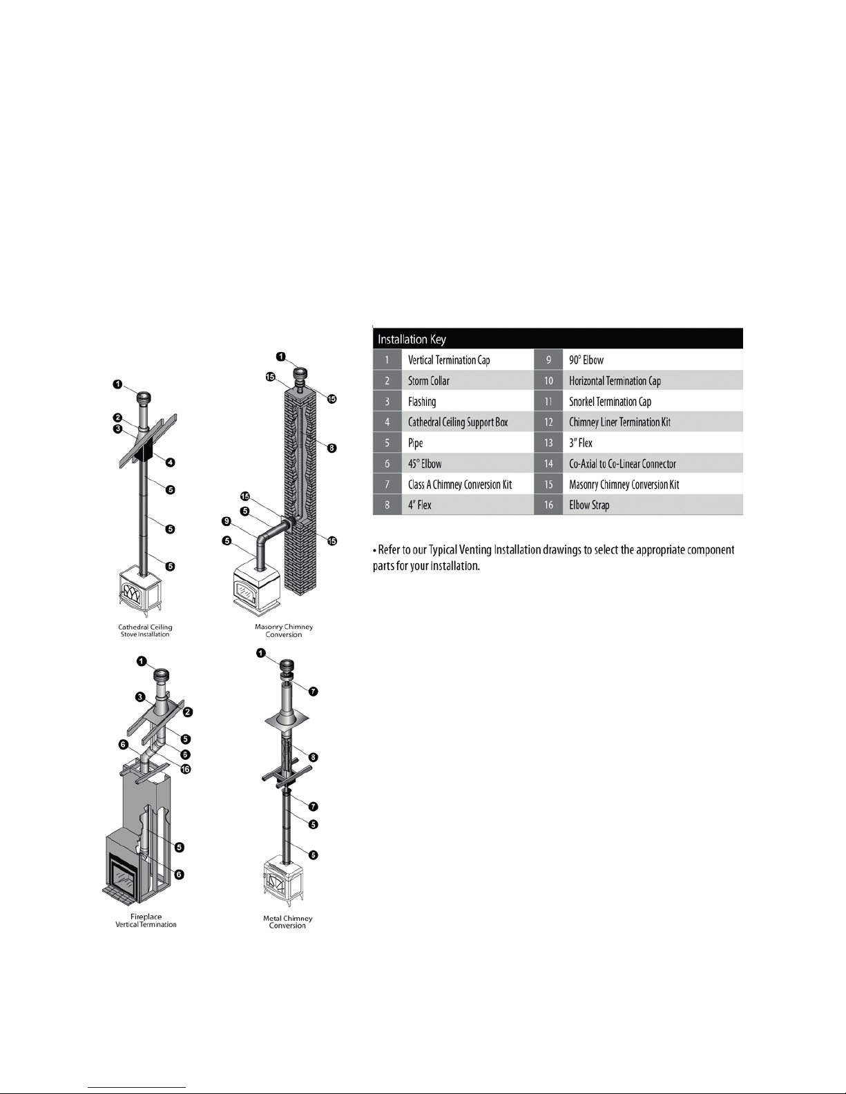
3.4.9 Typical installations

12
3.5 Fuel Bed Media and Arrangements
Please note that all arrangements are viewed from the front of the appliance, with the main burner at the front
(e ect burner at the rear).
01 - 02 -
03 - 04 -
05 - 06 -
07 - 08 -
09 - 10 - 11 -
Lenga 500

13
Installation, Servicing and User Instructions | EN
Place log 03 on the burner plate as
shown on the image.
Place log 02 on burner port BP 1 as
shown on the image.
Make absolutely sure the log slides all
the way over the connection.
When arranging the media in the re, it is always important to keep the mainburner (MAIN) clear from
media unless otherwise instructed. The main burner needs to have an uninterupted connection with the
pilot burner (PILOT) and with with logs of the eff ectburner that are connected to burner port 1 and 2 (BP
1 and BP 2)

14
Place log 04 on the burner plate as
shown on the image. The log leans on
log 03 and against log 02.
Place log 01 on burner port BP 2 as
shown on the image. The log leans
against log 02 at the top.
Make absolutely sure the log slides all
the way over the connection.
Place log 05 on the left-back side of
the burner. The log rests on log 03.

15
Installation, Servicing and User Instructions | EN
Place log 08 in the left front corner on
the burner as shown on the image.
Place log 06 on the right side of the
burner as shown on the image.
Place log 07 in front left of the middle
as shown on the image.
Make absolutely sure the log doesn’t
block the main burner (MAIN).

16
Place the ceramic bers (10). on the
main burner (MAIN) and secure them
with some small embers (09).
Make absolutely sure the ember don’t
block the main burner (MAIN).
Scatter the remaining embers (09)
evenly on the burnerplate.
Make absolutely sure the embers don’t
block the main burner (MAIN).
Scatter the vermiculite grains (11)
evenly over the burnerplate.
Make absolutely sure the grains don’t
block the main burner (MAIN).
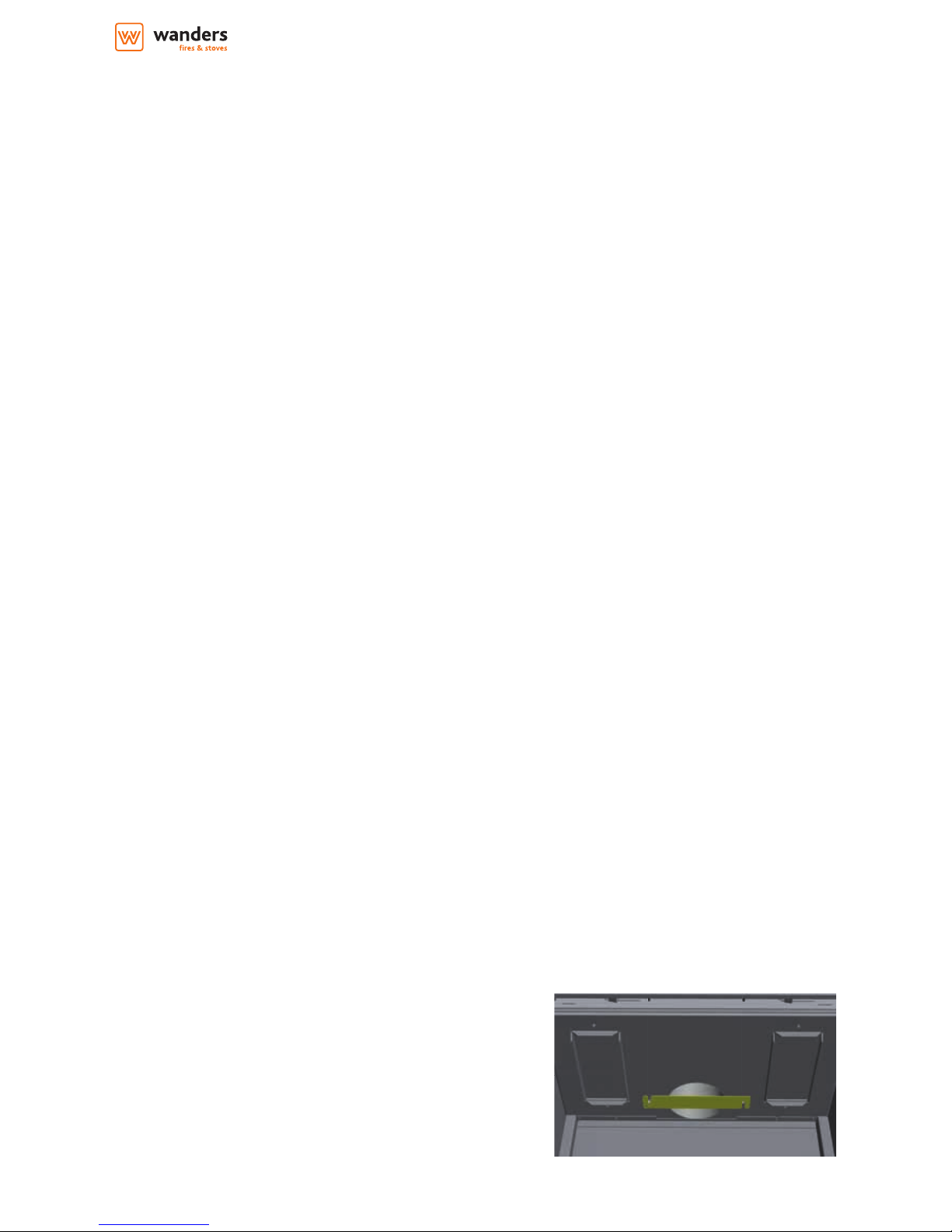
At this last step also ensure that the
front of the burner plate, as marked on
the image, is free of decoration. The
glass is installed in that area.

17
Installation, Servicing and User Instructions | EN
Lenga 800
11 - 12 -
09 - 10 -
01 - 02 -
03 - 04 -
05 - 06 -
07 - 08 -

18
13 - 14 - 15 -
When arranging the media in the re, it is always important to keep the mainburner (MAIN) clear from
media unless otherwise instructed. The main burner needs to have an uninterupted connection with the
pilot burner (PILOT) and with with logs of the eff ectburner that are connected to burner port 1, 2 and 3 (BP
1, BP 2 and BP 3)
Place log 04 on the burner plate as shown on the image.

19
Installation, Servicing and User Instructions | EN
Place log 06 on the burner plate as shown on the image.
Place log 09 on the left side of the burner plate as shown on the image.
Place log 08 on the right side of the burner plate as shown on the image. The log leans against log 04.

20
Place log 05 on the back of the burner plate as shown on the image.
Place log 07 on the left of the burner plate as shown on the image.
Place log 01 on burner port BP 3 as shown on the image. The log leans against log 04.
Make absolutely sure the log slides all the way over the connection.

21
Installation, Servicing and User Instructions | EN
Place log 02 on burner port BP 2 as shown on the image. The log leans against log 01.
Make absolutely sure the log slides all the way over the connection.
Place log 03 on burner port BP 1 as shown on the image. The log leans against log 02.
Make absolutely sure the log slides all the way over the connection.
Place the ceramic bers (14). on the main burner (MAIN) and secure them with some small embers (13).
Make absolutely sure the ember don’t block the main burner (MAIN).

22
Scatter the remaining embers (13) evenly on the burnerplate.
Make absolutely sure the embers don’t block the main burner (MAIN).
Place log 10 on the front of the burner plate as shown on the image.
Place log 11 on the embers between log 02 and 09 as shown on the image.

23
Installation, Servicing and User Instructions | EN
Place log 12 on the embers in the left back corner as shown on the image.
Scatter the vermiculite grains (15) evenly over the burnerplate.
Make absolutely sure the grains don’t block the main burner (MAIN).
At this last step also ensure that the front of the burner plate, as marked on the image, is free of decoration. The glass
is installed in that area.

24
3.6 Commissioning the Appliance
3.6.1 Pilot Ignition Check
1. Ignite the pilot light as described in the User Instructions
2. Check that the pilot ame stays alight
3. Extinguish the pilot light
3.6.2 Main Burner Check
1. Ignite the pilot light as described in the User Instructions
2. Turn on the main burner as described in the User Instructions
3. Check that the pilot smoothly cross-lights to the main burner and that the main burner and pilot stay alight
4. Check the operation of the second “eect” burner as described in the User Instructions
5. Extinguish the appliance fully
3.6.3 Pressure Check
The appliance is preset to give the correct heat inputs as listed in the technical details. No further adjustment is
necessary. Always check the inlet pressure and burner pressure.
1. Turn o the gas valve on the appliance
2. Release the screw on the Inlet Pressure test point on the gas valve and connect a manometer
3. Check that the measured pressure is as the prescribed supply pressure
4. Perform the test when the appliance is burning on full (inc. “eect” burner) and with only the pilot alight
5. If the pressure is low, check the gas supply pipes are too a correct sizing
6. If the pressure is too high (more than 5 mbar over) the appliance may be installed, but the gas supply company
should be contacted
7. Release the screw on the Burner Pressure test point on the gas valve and connect a manometer
8. Check that the measured pressure is as detailed in the Technical details
9. The measured value should be within +/- 10% of the described value. If this is not the case, please contact the
supplier.
Note: After checking the pressures and removing the manometers, the screws in the Pressure
Test points must be closed, and the system must be checked for gas-tightness.
4. Servicing
Turn the appliance OFF and isolate the gas supply. Ensure the appliance is fully cold before attempting to start
servicing the appliance. No liability can be accepted by Wanders for injury caused by burning or scolding by a hot
appliance.
A suggested procedure for servicing is listed below.
A. Lay out dust sheet on ooring, mask o any special replace materials.
B. Remove Side Window Trims
C. Remove Bottom Window Trim
D. Remove Window Assembly
E. Carefully remove the Ceramic components (including Embers) or Gravels
F. Use a Vacuum cleaner to clean the top of the burners and grate
G. Remove Grate
H. Remove all 3 Burner Top assemblies, there are 3 M6 ange bolts holding each in
I. Using a vacuum cleaner, fully clean both Burner Top.
J. With the Burner Tops now removed, the Pilot and the heads of the injectors are clearly visible. Use the
vacuum cleaner and a soft brush to clean the pilot assembly and both Injectors. Never modify or bend the
Thermocouple
K. Replace the burner top assemblies and x in with the xings
L. Turn on the gas supply and check for leaks, check the burners and Pilot for good condition and operation

25
Installation, Servicing and User Instructions | EN
M. Replace Grate
N. Replace the Firebed arrangements
O. Replace Window Assembly and Trims
P. Check the ue system and terminal, making sure that the terminal vent is fully clear
Q. Light the appliance and test setting pressures
R. Check the safe operation of the appliance.
4.1 Cleaning the Ceramics
Remove the ceramics as detailed in A - E above.
Gently clean the ceramics in the open air, using a soft brush and a vacuum cleaner. Where necessary replace
damaged components only with genuine Wanders speci ed parts. Seal any scrap ceramics in plastic bags and
dispose at proper refuse sites. When using a vacuum cleaner, it is recommended that one with a HEPA ltering
system is used.
Re- t the Firebed arrangement, re-seal the appliance and check the safe operation of the appliance.
4.2 Servicing the Burners
Remove the Burner Top Assemblies as detailed in A - H above.
The pilot is now clearly visible, the pilot, including the Thermocouple, can be replaced/serviced by removing
raising the pilot assembly from its mounting. This is done by removing the two screws on the surface of the pilot.
The ttings on the under-side of the pilot can be un-done using a 10mm spanner where appropriate.
To access the Main Burner Injectors, the Burner base units must be removed. This is done by removing the six
bolts (M6, 10mm spanner) holding the burner in. With these six bolts removed, the Burner base can be raised up
through the Firebox, and the Injectors can be easily accessed.
When replacing any parts use only original Wanders speci ed parts.
4.3 Opening the Glass
• Place the suction lifter on the middle of the glass. Make sure the glass is not hot.
• Open the glass clamps with the enclosed hook.
• Pull the glass slightly towards you.
• Lift the glass slightly and pull to bottom towards you.
• Put the glass aside carefully.
Terugplaatsen van de glasruit
• Place the glass at the base of the mainburner. Make sure the area is clear of any media covering the burner.
• Push the top of the glass in its place. Make sure the 2 steel tabs lock in the frame of the appliance.
• Pull the glass clamps down to lock the glass.
• Remove the suction lifter.

26
5. Technical Information
5.1 Countries of use
Code Country Natural LPG
AT Austria I2H, G20 at 20 mbar I3P(50), G31 at 50 mbar; I3B/P(50), G30/G31 at 50 mbar
BE Belgium I2E+, G20/G25 at 20/25 mbar
I3+, G31/G31 at 28/37 mbar; I3P(37), G31 at 37 mbar;
I3B/P(30), G30/G31 at 30 mbar
BG Bulgaria I2H, G20 at 20 mbar I3B/P(30), G30/G31 at 30 mbar
CH Switzerland I2H, G20 at 20 mbar
I3P(50), G31 at 50 mbar; I3+, G31/G31 at 28/37 mbar;
I3P(37), G31 at 37 mbar; I3B/P(50), G30/G31 at 50 mbar
CY Cyprus I2H, G20 at 20 mbar
I3+, G31/G31 at 28/37 mbar; I3B/P(30), G30/G31 at 30
mbar
CZ Czech Republic I2H, G20 at 20 mbar
I3P(50), G31 at 50 mbar; I3+, G31/G31 at 28/37 mbar;
I3P(37), G31 at 37 mbar; I3B/P(50), G30/G31 at 50 mbar
DE Germany I2ELL, G25 at 20 mbar¹; I2E, G20 at 20 mbar I3P(50), G31 at 50 mbar; I3B/P(50), G30/G31 at 50 mbar
DK Denmark I2H, G20 at 20 mbar I3B/P(30),G30/G31 at 30 mbar
EE Estonia I2H, G20 at 20 mbar I3B/P(30),G30/G31 at 30 mbar
ES Spain I2H, G20 at 20 mbar I3+, G31/G31 at 28/37 mbar; I3P(37), G31 at 37 mbar
FI Finland I2H, G20 at 20 mbar I3P(30), G31 at 30 mbar; I3B/P(30), G30/G31 at 30 mbar
FR France I2E+, G20/G25 at 20/25 mbar
I3+, G31/G31 at 28/37 mbar; I3P(37), G31 at 37 mbar;
I3B/P(30), G30/G31 at 30 mbar; I3B/P(50), G30/G31 at 50
mbar
GB United Kingdom I2H, G20 at 20 mbar
I3+, G31/G31 at 28/37 mbar; I3P(37), G31 at 37 mbar;
I3B/P(30), G30/G31 at 30 mbar
GR Greece I2H, G20 at 20 mbar
I3+, G31/G31 at 28/37 mbar; I3P(37), G31 at 37 mbar;
I3B/P(30), G30/G31 at 30 mbar
HU Hungary I3B/P(30), G30/G31 at 30 mbar
HR Croatia I2H, G20 at 20 mbar I3P(37), G31 at 37 mbar; I3B/P(30), G30/G31 at 30 mbar
IE Ireland I2H, G20 at 20 mbar I3+, G31/G31 at 28/37 mbar; I3P(37), G31 at 37 mbar
IS Iceland
IT Italy I2H, G20 at 20 mbar
I3+, G31/G31 at 28/37 mbar; I3P(37), G31 at 37 mbar;
I3B/P(30), G30/G31 at 30 mbar
LT Lithuania I2H, G20 at 20 mbar
I3+, G31/G31 at 28/37 mbar; I3P(37), G31 at 37 mbar;
I3B/P(30), G30/G31 at 30 mbar
LU Luxembourg I2E, G20 at 20 mbar
LV Latvia I2H, G20 at 20 mbar
MT Malta I3B/P(30), G30/G31 at 30 mbar
NL The Netherlands I2L/ I2EK, G25/G25.3 at 25 mbar
I3P(50), G31 at 50 mbar; I3P(30), G31 at 30 mbar; I3P(37),
G31 at 37 mbar; I3B/P(30), G30/G31 at 30 mbar
NO Norway I2H, G20 at 20 mbar I3B/P(30), G30/G31 at 30 mbar
PL Poland I2E, G20 at 20 mbar I3P(37), G31 at 37 mbar
PT Portugal I2H, G20 at 20 mbar I3+, G31/G31 at 28/37 mbar; I3P(37), G31 at 37 mbar
RO Romania I2E, G20 at 20 mbar I3P(30), G31 at 30 mbar; I3B/P(30), G30/G31 at 30 mbar
SE Sweden I2H, G20 at 20 mbar I3B/P(30), G30/G31 at 30 mbar
SL Slovenia I2H, G20 at 20 mbar
I3+, G31/G31 at 28/37 mbar; I3P(37), G31 at 37 mbar;
I3B/P(30), G30/G31 at 30 mbar
SK Slovakia I2H, G20 at 20 mbar
I3P(50), G31 at 50 mbar; I3+, G31/G31 at 28/37 mbar;
I3P(37), G31 at 37 mbar; I3B/P(30), G30/G31 at 30 mbar;
I3B/P(50), G30/G31 at 50
TR Turkey I2H, G20 at 20 mbar
I3+, G31/G31 at 28/37 mbar; I3P(37), G31 at 37 mbar;
I3B/P(30), G30/G31 at 30 mbar

27
Installation, Servicing and User Instructions | EN
5.2 Technical Data
Product Identication Number: 0359CO0001254
5.2.1 Lenga 500
Gas type
G20 G20/G25 G25/G25.3 G20/G25* G30/G31 G31
I2H, I2E I2E+ I2L/I2K I2ELL
I3B/P
(30/50)
I3+
I3P
(37/50)
I3P (30)
Supply Pressure mbar 20 20/25 25 20 30/50 28-30/37 37/50 30
Nominal Heat Input Gross (Hs) kW 10,5 10,5 10,3 10,5 11,5 11,5 11,5 9,7
Nominal Heat Input Nett (Hi) kW 9,5 9,5 9,3 9,5 10,6 10,6 10,6 9,0
Consumption m
3
/hr 1,022
1,022 /
1,103
1,117 1,117 0,204 0,204 0,403 0,341
Burner Pressure (hot) mbar 18,8 18,8 23,7 18,8 28,3 28,3 35,0 29,0
Injector Code 120 (middle), 320 (right), 220 (left) 100 (middle), 120 (right), 100 (left)
Pilot 440-1350-xx (31.2 inj) 440-1350-xx (27.1 inj)
Eciency Class 2
Nox Class 5
Type C11/C31
*) I2ELL Injectors: 120 (middle), 380 (right), 360 (left)
5.2.2. Lenga 800
Gas type
G20 G20/G25 G25/G25.3 G20/G25* G30/G31 G31
I2H, I2E I2E+ I2L/I2K I2ELL
I3B/P
(30/50)
I3+
I3P
(37/50)
I3P
(30)
Supply Pressure mbar 20 20/25 25 20 30/50 28-30/37 37/50 30
Nominal Heat Input Gross (Hs) kW 14,5 14,5 13,7 14,5 14,0 14,0 14,0 12,0
Nominal Heat Input Nett (Hi) kW 13,1 13,1 12,3 13,1 12,9 12,9 12,9 11,1
Consumption m
3
/hr 1,388
1,388 /
1,482
1,490 1,482 0,398 0,398 0,517 0,444
Burner Pressure (hot) mbar 17,8
17,8 /
22,3
22,5 18,0 28,4 28,4 36,4 28,9
Injector Code
160 (middle), 320 (right), 320 (front left), 280
(back left)
100 (middle), 120 (right), 120 (front left),
100 (back left)
Pilot 440-1350-xx (31.2 inj) 440-1350-xx (27.1 inj)
Eciency Class 2
Nox Class 5
Type C11/C31
*) I2ELL Injectors: 160 (middle), 360 (right), 360 (front left), 320 (back left)

28
5.3 Dimensions
5.3.1.a Lenga 500 A
5.3.1.b Lenga 500 AB
388,30
366,00
1061,70
1170,93
118,40
893,50
469,00
554,00
100/150
M&G
103,43
94,00
488,00
120,40
488,00
575,00
894,50
254,80
894,50
479,00
100/150
M&G
368,00
1061,70
1170,93
93,00
103
,43
388,30

29
Installation, Servicing and User Instructions | EN
5.3.1.c Lenga 500 AE
5.3.1.d Lenga 500 ABE
120,40
488,00
575,00
100/150
M&G
388,30
894,50
254,80
894,50
479,00
1061,70
1170,93
93,00
,43
376,00
488,00
600,00
100/150
M&G
894,50
500,00
894,50
254,80
1067,50
1170,93
120,40
93,00
103,43
288,50
192,43
1229,93
898,50
554,00
554,00

30
5.3.2.a Lenga 800 A
5.3.2.b Lenga 800 AB
120,40
788,00
875,00
130/200
M&G
368,00
388,30
744,50
254,80
744,50
779,00
912,00
1020,93
93,00
,43
120,40
788,00
854,00
130/200
M&G
743,50
769,00
94,00
103
,43
368,00
390,30
911,70
1020,93

31
Installation, Servicing and User Instructions | EN
5.3.2.c Lenga 800 AE
5.3.2.d Lenga 800 ABE
120,40
788,00
875,00
130/200
M&G
368,00
744,50
779,00
743,99
254,80
912,00
1020,93
103
,43
93,00
390,30
854,00
120,40
900,00
130/200
M&G
376,00
744,50
254,80
917,50
1020,93
93,00
744,50
800,00

32
“myfire” App for Android/iOS
Handset
B6R-H8(9)…P…
Light
Fan
Ignition Cable G60-ZKIS…
Interrupter Block
G60-ZUS…
Combination Control
GV60…
Mains Power
(115/230 V; AC)
V Module
G6R-BU(E)…
Cable
G6R-CBV…
Home Network
NOTE:
Components are not actual size.
OPTIONAL WiFi/APP (excl. tablet and router)
OPTIONAL MODULE (INK.3255)
Electrical diagram

33
Installation, Servicing and User Instructions | EN

34

garantiebewijs / guarantee certicate / certicat de garantie / garantieschein
Wanders res & stoves
Amtweg 4
7077 AL Netterden
The Netherlands
T: +31 (0) 315 - 386 414
F: +31 (0) 315 - 386 201
E: service@wanders.nl
I: www.wanders.com
model / model / modèle / modell
serienummer / serial number
nr. de série / seriennummer
aankoop datum / date of purchase
date de láchat / kaufdatum
s'il vous plaît joindre copie de la preuve d'achatplease enclose copy of proof of purchase bitte kopie vom kaufbeleg beifügenkopie aankoopbewijs bijvoegen aub
/ / /
naam / name / nom / name
adres / address / adresse / adresse
postcode - plaats / postal code - town
code postal - lieu / postleitzahl - ort
land / country / pays / land
naam / name / nom / name
adres / address / adresse / adresse
postcode - plaats / postal code - town
code postal - lieu / postleitzahl - ort
land / country / pays / land
dealer gegevens / dealer information / l'information revendeur / händler informationen
Onder de garantie vallen alle gebreken die te herleiden zijn
tot materiaal- en constructiefouten. In die gevallen ontvangt
u gratis nieuwe onderdelen. Arbeidsloon en andere kosten
vallen niet onder de garantie. Defecte onderdelen kunt
franco toezenden aan WANDERS Metaalproducten B.V.,
Amtweg 4, 7077 AL, Netterden.
Voordat de haard geplaatst wordt, moet u controleren of er
zichtbare schade is aan het toestel.
In dat geval moet u het toestel niet accepteren, maar contact
opnemen met uw leverancier.
Buiten de garantie vallen: het glas, storingen ontstaan
door onoordeelkundig gebruik; niet juiste naleving van de
landelijke voorschriften en de bijgevoegde installatie- en
bedieningsvoorschrif-ten; installatie door een niet door
WANDERS erkend installateur of dealer; verwaarlozing van
het toestel en bij wisseling van eigenaar. De garantie vervalt
ook bij gebruik van een verkeerde brandstof.
WANDERS is niet verantwoordelijk voor eventuele
scheuren in sierpleisterwerk en verkleuringen van wanden,
plafonds en/of roosters na het stoken van de haard.
Verkleuringen kunnen ontstaan doordat stofdeeltjes
verbranden in de convectiemantel. Om de kans op
scheuren in sierpleisterwerk en eventuele verkleuringen te
minimaliseren verwijzen wij naar het advies dat gegeven
wordt in de sfeerhaardenbranche. Uw installateur kan u
hierover informeren.
Klachten worden in behandeling genomen nadat de
verkooprma/installateur of het gasbedrijf een klacht
heeft ingediend, vergezeld van de aankoopdatum en een
kopie van de aankoopbon. Reparaties geven geen recht op
verlenging van de garantietermijn.
Alle gevolgschade wordt uitgesloten.
The guarantee includes all defects which can be reduced
to aws in material and construction, in which case you
will receive the new parts free of charge. Labour costs
or other expenses are not covered by the guarantee.
You can send defect parts (shipping paid) to WANDERS
Metaalproducten B.V., Amtweg 4, 7077 AL in Netterden
[The Netherlands].
Before installing your stove you must check if there is any
visible damage to the unit. If there is, do not accept the
unit and contact your supplier.
The guarantee does not include: the glass, failure due
to improper use; non-compliance with the national
regulations and enclosed installation and operating
instructions; installation by an installer of dealer who is
not acknowledged by WANDERS, negligence of the unit
and change of owner. The guarantee is also disclaimed
when a wrong fuel is used.
WANDERS disclaims responsibility for any cracks in
stuccoed walls or discolouration of walls, ceilings and/
or grates after burning the replace. Discolouration can
be caused when dust particles burn in the convection
cover. To minimize the chance of cracks in stucco and
discolouration we refer to the advice given for decorative
hearths. Your installer can give you more information.
Any complaints will be dealt with after the sales rm,
the installer has led a complaint and sent a copy of the
purchase receipt with purchase date. Any repairs do not
entitle you to extend the guarantee term.
All consequential damages or loss are excluded.
La garantie couvre tous les défauts qui résulteraient des vices
de matière et de construction. Dans ces cas, vous recevrez des
pièces nouvelles gratuitement. Les frais de salaire et les autres frais
n’entrent pas dans le champ de la garantie. Les pièces défectueuses
peuvent être expédiées franco à WANDERS Metaalproducten B.V.,
Amtweg 4, 7077 AL, Netterden, Pays-Bas .
Avant de procéder à la pose de l’appareil vous devrez vérifier si
le poêle ne présente pas des dommages visibles. Dans ce cas, il
ne faut pas accepter l’appareil en prendre contact avec votre
fournisseur.
La garantie ne couvre pas la vitre et ne s’applique pas aux
dérangements provenant d’une mauvaise utilisation, d’un
manque de respect de la réglementation nationale et des
instructions d’installation et d’emploi fournis avec l’appareil, d’une
installation effectuée par un installateur ou revendeur non-agréé
par WANDERS , d’un défaut d’entretien et en cas où le poêle serait
passé en d’autres mains. La garantie ne s’applique pas non plus si
un combustible non approprié a été utilisé.
WANDERS n’est pas responsable des éventuelles fissures au
plâtrage de parement et des décolorations des parois, plafonds et/
ou grilles après le chauffage du poêle. Les décolorations peuvent
être causées par la combustion des grains de poussière dans le
manteau de convection. Pour réduire au maximum les fissures au
plâtrage et les décolorations éventuelles, veuillez vous reporter
aux consignes généralement données dans le commerce sur les
poêles d’ambiance. Votre installateur vous renseignera.
Les plaintes sont examinées après qu’elles ont été présentées
par l’établissement de vente, par l’installateur, accompagnées
d’une copie de la facture d’achat indiquant la date d’achat. Les
réparations ne donnent pas droit à une prorogation de la durée
de garantie.
Les dommages conséquents sont exclus.
Unter diese Garantie fallen alle Mängel die auf Materialoder Konstruktionsfehler zurückzuführen sind. In
diesen Fällen erhalten Sie gratis neue Ersatzteile. Der
Arbeitslohn und andere Kosten fallen nicht unter die
Garantie. Fehlerhafte Teile können Sie franco an WANDERS
Metaalproducten B.V. Amtweg 4, 7077 AL Netterden
(Holland) schicken.
Vor Montage des Ofens müssen Sie kontrollieren ob das
Gerät keine sichtbaren Schäden aufweist. In dem Fall
müssen Sie das Gerät nicht akzeptieren, müssen aber mit
Ihren Lieferanten Kontakt aufnehmen.
Nicht unter die Garantie fallen: Störungen die durch nicht
sachgemäßen Gebrauch entstanden sind; nicht strikte
Befolgung der Installations- und Bedienungsvorschriften;
Montage durch einen nicht von WANDERS anerkannten
Installateur, Vernachlässigung des Ofens und bei einem
Wechsel des Besitzers. Die Garantie verfällt auch, wenn
verkehrtes Heizmaterial benützt wurde.
Wanders ist nicht verantwortlich für eventuelle Risse im
Feinputz und Verfärbungen der Wände, Decken und/
oder Roste nach Heizen des Ofens. Verfärbungen können
entstehen weil Staubteilchen im Konvektionsmantel
verbrennen. Um eventuelle Risse im Feinputz und
Verfärbungen zu minimalisieren, verweisen Sie auf den
Rat der von der Branche für Kaminöfen gegeben wird. Ihr
Installateur kann Sie darüber informieren.
Reklamationen werden erst dann behandelt, wenn
die Verkaufsrma, der Installateur eine Reklamation,
zusammen mit einer Kopie des Kassenzettels mit
Kaufdatum, eingereicht hat. Reparaturen berechtigen
nicht zu einer Verlängerung der Garantie.
Alle Folgeschäden sind ausgeschlossen.

Wanders res & stoves
Amtweg 4
7077 AL NETTERDEN
Nederland
Tel: +31 (0)315 - 386 414
Fax: +31 (0)315 - 386 201
info@wanders.nl
www.wanders.nl
@Wanders_ res
www.facebook.com/Wanders resstoves
Type- en zetfouten voorbehouden. Wanders res & stoves is een onderdeel van de Wanders Groep
© 2014 Wanders Metaalproducten B.V. - All rights reserved
wanders res
wandersnetterden
 Loading...