

WANDERS Lenga 500, lenga 800 Installation, Servicing And User Instructions Manual
LENGA
Installation, Servicing and User instructions
500 - 800 | Front, Bay and Corner
EN
v.1.0-112016
This appliance has been tested and certied for other counties (see technical data). However to install
appliance in other countries, modication of the appliance and its method of installation may be
necessary in order to use the appliance safely and correctly. The manual for the local language must be
obtained. Contact Wanders for further information.
2
© Copyright 2016 Wanders res & stoves
The information contained herein is subject to change without notice. Wanders res & stoves shall not be liable for technical or editorial errors or omissions contained herein.
1. General Notes 3
2. User instructions 4
2.1 First Time of Operation 4
2.2 Remote control 4
2.3 Wanders Eco Wave App control (optional) 4
2.4 Cleaning and Maintenance 4
3. Installation instructions. 4
3.1 Gas Connection 4
3.2 Ventilation 4
3.3 Appliance Fireplace Installation 4
3.3.1 Building the Fireplace 5
3.3.2 Built-In Fireplace Sizing 5
3.3.3 Mantel Clearances 6
3.4 Flue Connection 8
3.4.1. General Notes 8
3.4.2 Timber Frame Construction 8
3.4.3 Carport or Building Extension 8
3.4.4 Basements, Lightwells and Retaining walls 8
3.4.5 Terminal Locations 9
3.4.6 Horizontal Wall Vent Termination type C11 10
3.4.7 Vertical Roof Vent Termination type C31 10
3.4.8 Flue restrictors to be tted 10
3.4.9 Typical installations 11
3.5 Fuel Bed Media and Arrangements 12
Lenga 500 12
Lenga 800 17
3.6 Commissioning the Appliance 24
3.6.1 Pilot Ignition Check 24
3.6.2 Main Burner Check 24
3.6.3 Pressure Check 24
4. Servicing 24
4.1 Cleaning the Ceramics 25
4.2 Servicing the Burners 25
4.3 Opening the Glass 25
Terugplaatsen van de glasruit 25
5. Technical Information 26
5.1 Countries of use 26
5.2 Technical Data 27
5.2.1 Lenga 500 27
5.2.2. Lenga 800 27
5.3 Dimensions 28
5.3.1.a Lenga 500 A 28
5.3.1.b Lenga 500 AB 28
5.3.1.c Lenga 500 AE 29
5.3.1.d Lenga 500 ABE 29
5.3.2.a Lenga 800 A 30
5.3.2.b Lenga 800 AB 30
5.3.2.c Lenga 800 AE 31
5.3.2.d Lenga 800 ABE 31
Electrical diagram 32

3
Installation, Servicing and User Instructions | EN
1. General Notes
• This Wanders gas appliance is a High Eciency, Balanced Flue Live Fuel Eect appliance. It provides radiant
and convected heat using the latest burner technology. As well as having a variable heat output, these res
also utilise a special control system that allows the appliance to use two burners for high output or a single
burner for lower outputs.
• One of the burners will be designated as the “Main” Burner, this is the Front, the second burner will be
designated as the “Eect” Burner. The Eect burner can be switched ON or OFF whilst the appliance is alight.
• Before Installation, check that the local distribution conditions, nature of the gas and pressure, and adjustment
of the appliance are compatible.
• This appliance is intended for use on a gas installation with a governed meter.
• This Gas Installation may only be installed by a registered professional competent person (Gas Safe installer in
the UK). The installation must adhere to the requirements of the local and national Building regulations and
national standards. The installation manual must also be followed.
• Ensure that the Flue Terminal is not in any way obstructed and is clear of vegetation, i.e. trees, shrubs etc. and
that no objects are leant against the terminal or guard.
• Always clean the Window Panel before the re is ignited. Any nger prints must be removed, as these will be
burnt into the glass and will be un-removable.
• Do not operate this appliance if the glass panel has been broken (or cracked), removed or is open.
• The appliance is designed to t numerous installation situations as listed in these installation instructions.
However only ue approved by Wanders for this appliance may be used.
• This appliance is a balanced ue product and is room sealed and as such requires no additional ventilation for
operation. However an adequate supply of fresh air to maintain temperatures and a comfortable environment
is recommended.
• This appliance is designed as a heating appliance, and as such will get very hot in operation; all surfaces (except
the controls and access door) are considered to be working surfaces and as such should not be touched. The
front windows and surrounds are not considered to be fully secure guards against accidental contact. It is
recommended that an approved re screen be used if children, the elderly or persons with limited mobility
are to be present in the same area.
• Do not place curtains, laundry, furniture etc. within a safe distance of 300mm of this appliance.
• Do not attempt to burn rubbish on this appliance.
• If this appliance is extinguished, on purpose or other, no attempt to relight should be made within 3 minutes.

4
2. User instructions
2.1 First Time of Operation
Before igniting the appliance, ensure that all packaging, safety stickers and any protective wrapping have been
removed, and that the glass has been cleaned, including all ngerprints from the glass.
Ensure that the room is adequately ventilated the rst time that the appliance is ignited; we would recommend
opening windows if possible. Run the appliance at full setting for a few hours so that the paint gets an opportunity
to fully cure. During this period it is possible for some fumes and vapours to be given o. We would recommend
keeping children and pets out of the area at this time.
2.2 Remote control
Please refer to the separately added manual for the SYMAX remote control system.
2.3 Wanders Eco Wave App control (optional)
Please refer to the separately added manual for the Wanders Eco Wave control system.
2.4 Cleaning and Maintenance
This appliance should be inspected and serviced once a year by a qualied, competent and registered person.
The inspection and maintenance must at least ensure that the appliance is working correctly and safely. It is
advisable to clean the appliance of any dust and debris before regularly during the heating season and especially
if the appliance has not been used for some time. This can be done with a soft brush and a vacuum cleaner or a
damp cloth and if required a non-abrasive cleaning agent. Do not use corrosive or abrasive substances to clean
the appliance.
3. Installation instructions.
Before commencing Installation, conrm that the details on the appliance data plate correspond to the local
distribution conditions, gas type and pressure to which the appliance is to be installed.
Ensure that gas supply and supply pipe is capable of delivering the required volume and pressure of gas and is in
accordance with the rules in force.
3.1 Gas Connection
This appliance has a gas inlet connection of Ø 8mm.
3.2 Ventilation
This appliance is a Balanced Flue room sealed appliance, and as such needs no additional ventilation. However an
adequate supply of fresh air to maintain temperatures and a comfortable environment is recommended.
This appliance may be installed in a completely sealed or mechanically ventilated house.
3.3 Appliance Fireplace Installation
• Determine the position required for the appliance.
• Create a gas connection for the appliance in approximately the correct location for the gas controls.
• The gas controls are connected to the Burner of the appliance. These controls need to be located in the
control access box, so an appropriate position for the access box needs to be determined.
• This appliance has fully adjustable legs, these must me set to the desired length before the ue position is
nalised. Fine adjustment of the legs is available via the feet.
• Do not make any adjustments to the appliance, except the leg length.
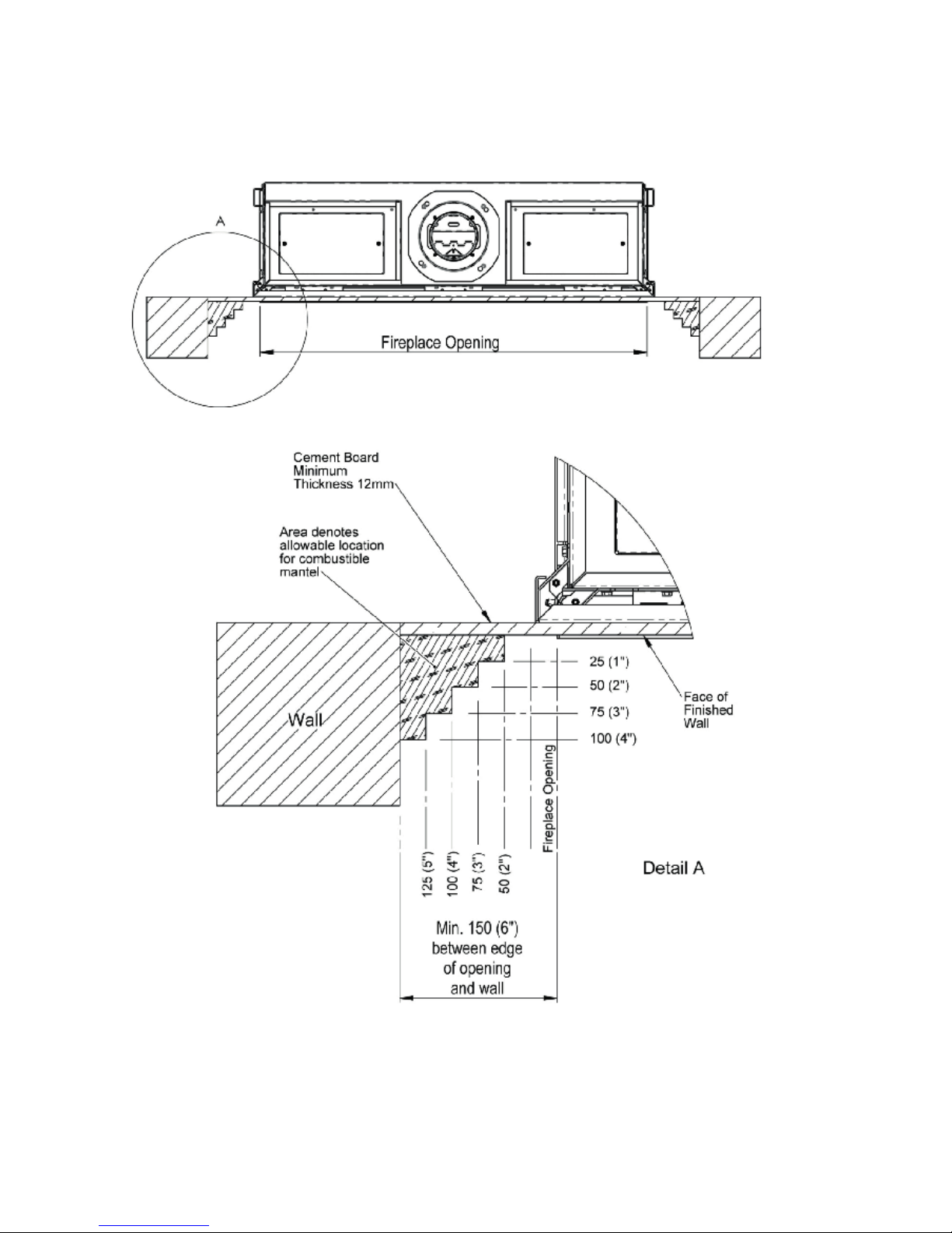
• The appliance should be tted with a minimum clearance of 150mm from any combustible objects or
materials; this includes any combustible materials used for the replace construction. This clearance distance
can be reduced to 50mm if a Cement Board, of minimum thickness 12mm is used. This Cement Board will act
as a Thermal Break.
• The clearance distance of the Flue from combustibles must not be less than 75mm. This dimension can be
reduced to 25mm as the distance from the underside and the sides of Horizontal Flue runs.
5
Installation, Servicing and User Instructions | EN
• As this is a room sealed appliance and the appliance stands on appropriate legs, a hearth is not required for
this appliance.
• The Fireplace should be ventilated with openings giving a total free vent area of 200 cm².
• A gap of 50mm should be left all round the appliance.
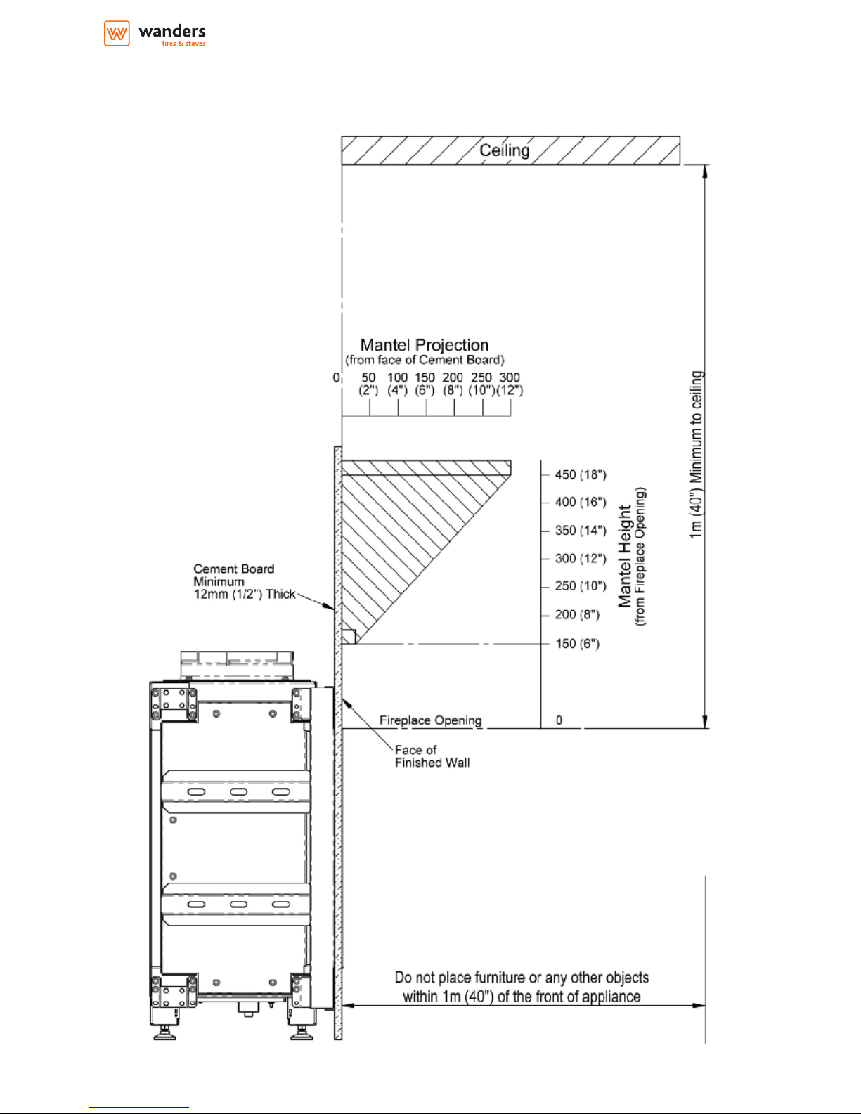
• If a shelf is to be tted above the replace opening, a gap of 150mm minimum should be left between the
opening and the shelf.See section 3.3.3, Mantel Clearances.
• The brackets supplied may be used for securing the appliance to a rear wall.
3.3.1 Building the Fireplace
• Construct a studwork replace to the desired sizes, minimum sizes are shown in section 3.3.2. Any combustible
material used to construct the Fireplace must not be closer than the minimum dimensions quoted in section
3.3 above. Cement Board of minimum thickness 12mm, can be used as a Thermal Break and can be used
directly against the Frame Face on the appliance.
• Do not use insulation material (or other) to pack the void around or above the appliance.
• Provide ventilation from the replace to the minimum amount quoted in 3.3 above.
• Provide a cut-out for the Control Access Door.
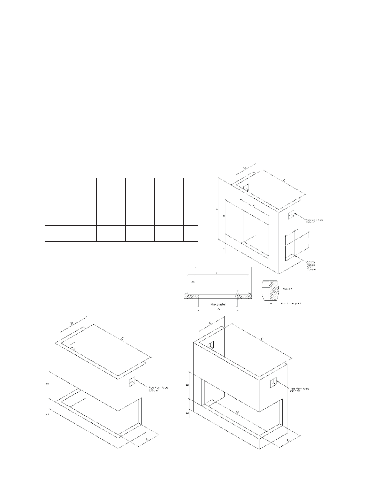
3.3.2 Built-In Fireplace Sizing
(assuming a Cement Board Lining is used)
Appliance
A
minB minC minD min
E
min
F
minG minH min
Lenga 500 A 552 905 655 415 195 1235 n/a n/a
Lenga 500 ABC n/a 905 600 415 195 1235 290 n/a
Lenga 500 AB/AC n/a 905 640 415 195 1235 290 505
Lenga 800 A 852 755 955 415 195 1083 n/a n/a
Lenga 800 ABC n/a 755 900 415 195 1083 290 n/a
Lenga 800 AB/AC n/a 755 940 415 195 1083 290 805
6
3.3.3 Mantel Clearances
3.3.3.a Combustible Mantel - side view
7
Installation, Servicing and User Instructions | EN
3.3.3.b Combustible Mantel/Side Wall - top view

8
3.4 Flue Connection
3.4.1. General Notes
This appliance may be installed with a roof terminal (C31) or a wall terminal (C11).
This appliance may only be used with Balanced Flue (otherwise known as Concentric Flue) parts as specied by
Wanders. The Wanders specied ue parts have been approved with the appliance. If the appliance is installed
on non-Wanders approved parts, Wanders cannot guarantee or accept and responsibility for the proper and safe
working of the appliance.
The ue system must be constructed from the appliance upwards, with all joints being fully locked and sealed
using the Wanders specied parts. Flue systems approved for this Appliance:
• Muelink & Grol (M&G) Concentric.
• Poujoulat PGI.
• Metaloterm US.
3.4.2 Timber Frame Construction
Whilst it is possible to install room-sealed appliances in timber frame properties, great care needs to be taken to
ensure that the ue assembly does not interfere with the weather proong qualities of any outer wall which it
may penetrate. Before attempting this work, further details need to be referenced, (e.g. “Gas Installations in Timber
Frame Buildings” from the CORGI installer series in the UK).
3.4.3 Carport or Building Extension
Where a ue terminal is sited within a carport or building extension, it should have at least two completely open
and unobstructed sides. The distance between the lowest part of the roof and the top of the terminal should be
at least 600mm.
Note: A covered passageway should not be treated as a carport. Flues should not be sited in a covered passageway
between properties.
3.4.4 Basements, Lightwells and Retaining walls
Flue terminals should not be sited within the connes of a basement area, light well or external space formed by a
retaining wall, unless steps are taken to ensure the products of combustion can disperse safely at all times. It may
be possible to install this Balanced Flue system in such a location provided that it is not sited lower than 1m from
the top level of that area to allow combustion products to disperse safely.
Flue terminals should be sited to ensure total clearance of the combustion products in accordance with the
included information.
When the products of combustion are discharged, they should not cause a nuisance to adjoining or adjacent
properties and they should be positioned so that damage cannot occur to other parts of the building. If the outer
wall surface is constructed of combustible material, a non-combustible plate should be tted behind the terminal
projecting 25mm beyond the external edges of the terminal.
9
Installation, Servicing and User Instructions | EN
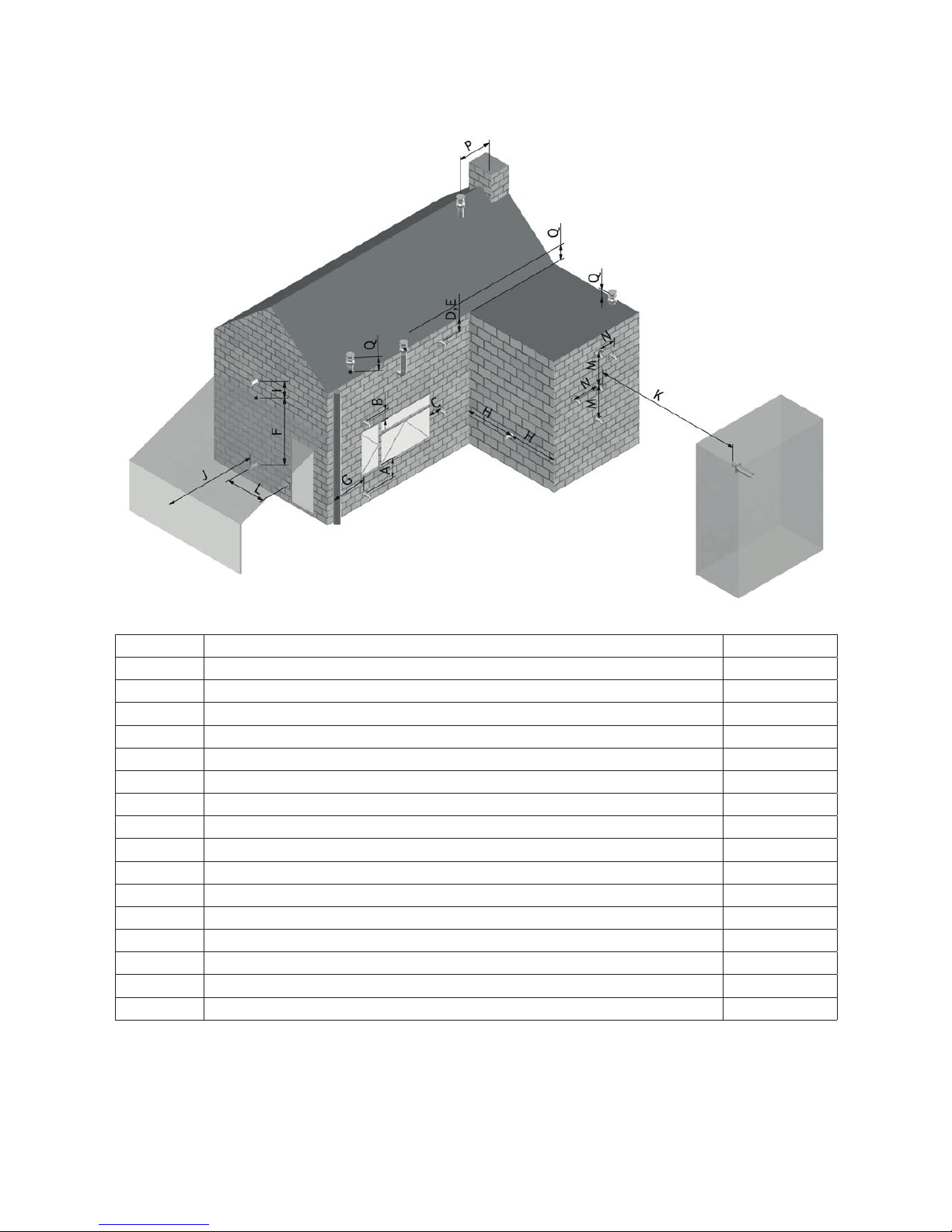
3.4.5 Terminal Locations
Dimension Terminal Position Distance (mm)
A* Directly below an opening, air brick, opening window etc. 600
B Above an opening, air brick, opening window etc. 300
C Adjacent to an opening, air brick, opening window etc. 400
D Below gutters, soil pipes or drain pipes 300
E Below eaves 300
F Below balconies or car port roof 600
G From a vertical drain pipe or soil pipe 300
H From an internal or external corner 600
I Above ground roof or balcony level 300
J From a surface facing the terminal 600
K From a terminal facing the terminal 600
L From an opening in the car port (e.g. door, window into the dwelling) 1200
M Vertically from a terminal on the same wall 1500
N Horizontally from a terminal on the same wall 300
P From a vertical structure on the roof 600
Q Above intersection with roof 150
* In addition, the terminal should not be nearer than 300mm to an opening in the building fabric
formed for the purpose of accommodating a built in element such as a window frame.
10
3.4.6 Horizontal Wall Vent Termination type C11
Flue sizing and regulations.
Lenga 500
• Ø100/150 Connector on appliance.
• Ø100/150 to be used throughout.
• Maximum horizontal length is 3 meters.
• Minimum vertical length directly on appliance is 1 meter.
• Maximum pipe extension for outside wall (H) is 2 x vertical pipe rise (V).
• Maximum length of the entire system (excl. outlet terminal) is 10 meters.
• Flue Terminal: Ø100/150 Part No. INK.4330
Lenga 800
• Ø130/200 Connector on appliance.
• Ø130/200 to be used throughout.
• Do NOT reduce to 100/150.
• Maximum horizontal length is 3 meters.
• Minimum vertical length directly on appliance is 1 meter.
• Maximum pipe extension for outside wall (H) is 4 x vertical pipe rise (V).
• Maximum length of the entire system (excl. outlet terminal) is 10 meters.
• Flue Terminal: Ø130/200 Part No. INK.4430
3.4.7 Vertical Roof Vent Termination type C31
Flue sizing and regulations.
Lenga 500
• Ø100/150 Connector on appliance.
• Ø100/150 to be used throughout.
• Maximum horizontal length is 3 meters.
• Minimum vertical length directly on appliance is 1 meter.
• Maximum length of the entire system (excl. outlet terminal) is 10 meters.
• Flue Terminal: Ø100/150 Part No. INK.4335
Lenga 800
• Ø130/200 Connector on appliance.
• Ø130/200 to be used throughout.
• Reducing to 100/150 is allowed if the ue run is entirely vertical with a maximum length of 10 meters. The rst
meter needs to be 130/200.
• Reducing to 100/150 is allowed when the ue run has elbows in it, but only at the very last moment just
before the roof outlet.
• Maximum horizontal length is 3 meters.
• Minimum vertical length directly on appliance is 1 meter.
• Maximum length of the entire system (excl. outlet terminal) is 10 meters.
• Reducer Ø130/200 > 100/150 Part No. INK.4490
• Flue Terminal: Ø100/150 Part No. INK.4430
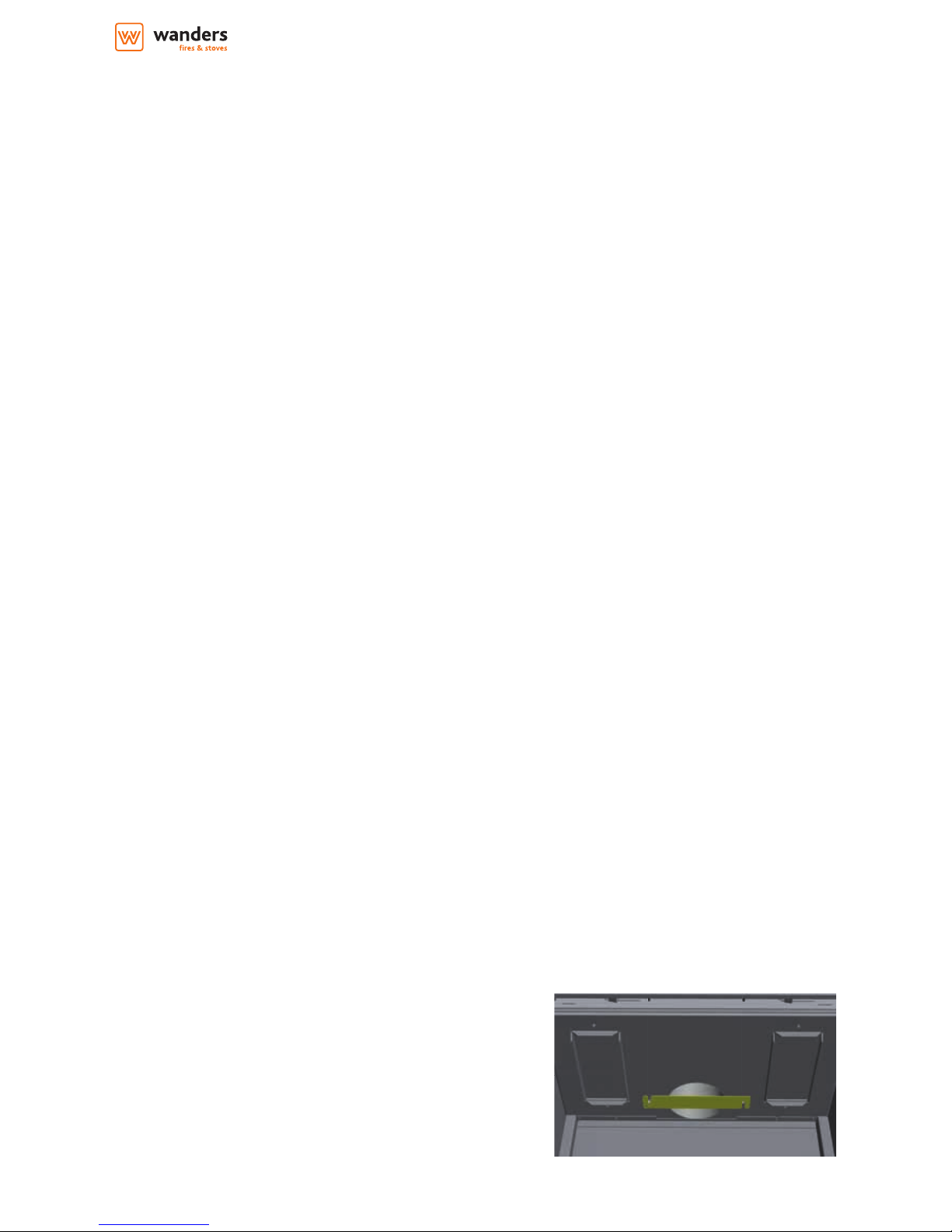
3.4.8 Flue restrictors to be tted
The restrictor can be installed with the pre-installed M5x20 bolts
Lenga 500
Wall terminal:
• Ø100/150, vertical rise 1 meter, no restrictor
• Ø100/150, vertical rise > 1 meter, 35 mm restrictor
Roof terminal:
• Ø100/150, vertical rise < 2 meter, 35 mm restrictor
• Ø100/150, vertical rise > 2 meter, 60 mm restrictor
11
Installation, Servicing and User Instructions | EN
Lenga 800
Wall terminal:
• Ø130/200, vertical rise 1 meter, no restrictor
• Ø130/200, vertical rise 1-2 meter, 35 mm restrictor
• Ø130/200, vertical rise > 2 meter, 50 mm restrictor
Roof terminal:
• Ø130/200, vertical rise < 1 meter, no restrictor
• Ø130/200, vertical rise 1-2 meter, 35 mm restrictor
• Ø130/200, vertical rise 2-4 meter, 50 mm restrictor
• Ø130/200, vertical rise > 4 meter, 60 mm restrictor
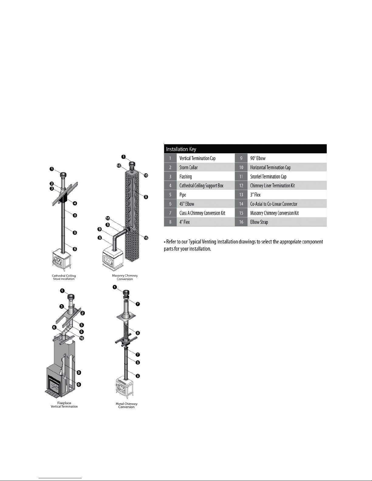
3.4.9 Typical installations
 Loading...