

WANDERS DANTA 500, DANTA 800, DANTA 1400, DANTA Koto, DANTA 1100 Installation, Servicing And User Instructions Manual
DANTA
installation, servicing and user instructions
500 - 800 - 1100 - 1400 - Koto
includes Front, Corner, Bay and Room Divider
IEGB
This appliance has been tested and certied for other counties (see technical data). However
to install appliance in other countries, modication of the appliance and its method
of installation may be necessary in order to use the appliance safely and correctly. The
manual for the local language must be obtained. Contact Wanders for further information.
v.3.3-082017


installation, servicing and user instructions manual | GB + IE
3
© Copyright 2014 Wanders res & stoves
The information contained herein is subject to change without notice. Wanders res & stoves shall not be liable for technical or editorial errors or omissions contained herein.
1. General Notes 4
2. User instructions 5
Operation (remote control with EcoWave) 5
Operation (optional Wanders EcoWave app) 5
2.1 First Time of Operation 5
2.2 Remote Control Overview 5
2.3 Batteries 6
2.4 Replacing the batteries 6
2.5 Setting the Transmitter code 6
2.6 To Ignite the appliance 6
2.7 To Turn the appliance OFF 7
2.8 Adjusting the Flame setting 7
2.9 Using the "Eect" Burner 7
2.10 Setting °C/24 hour or °F/12 hour clock 7
2.11 Setting the Time 7
2.12 Cleaning and Maintenance 7
3. Installation instructions 8
3.1 Gas Connection 8
3.2 Ventilation 8
3.3 Appliance Fireplace Installation 8
3.3.1 Building the Fireplace 8
3.3.2 Built-In Fireplace Sizing (assuming a Cement Board Lining is used) 9
3.3.4 Mantel Clearances 11
3.4 Flue Connection 13
3.4.1 General notes 13
3.4.2 Timber Frame Construction 13
3.4.3 Carport or Building Extension 13
3.4.4 Basements, Lightwells and Retaining walls 13
3.4.5 Terminal Locations 14
3.4.6 Horizontal Wall Vent Termination type C11 15
3.4.7 Vertical Roof Vent Termination C31 16
3.4.8 Typical Installations Roof Vent Termination C31 20
3.5 Fuel Bed Media and Arrangements 21
3.5.1 Danta 500 22
3.5.2 Danta 800 22
3.5.3 Danta 1100 23
3.5.4 Danta 1400 & Koto 24
3.5.5 Pebbles 25
3.5.6 Stones 25
3.6 Commissioning the Appliance 26
3.6.1 Pilot Ignition Check 26
3.6.2 Main Burner Check 26
3.6.3 Pressure Check 26
4. Servicing 27
4.1 Cleaning the Ceramics 27
4.2 Servicing the Burners 27
4.3 Spare parts 28
4.4 Flue pipes 28
5. Technical Information 29
5.1 Countries of Use 29
5.2 Technical Data 30
5.2.1 Danta 500 30
5.2.2 Danta 800 30
5.2.3 Danta 1100 & Koto 31
5.2.4 Danta 1400 31
6. Electric wiring 32

4
1. General Notes
This Wanders gas appliance is a High Eciency, Balanced Flue Live Fuel Eect appliance. It provides radiant and
convected heat using the latest burner technology. As well as having a variable heat output, these res also utilise
a special control system that allows the appliance to use two burners for high output or a single burner for lower
outputs.
One of the burners will be designated as the "Main" Burner, this is the Front, the second burner will be designated
as the "Eect" Burner. The Eect burner can be switched ON or OFF whilst the appliance is alight.
Before Installation, check that the local distribution conditions, nature of the gas and pressure, and adjustment of
the appliance are compatible.
This appliance is intended for use on a gas installation with a governed meter.
This Gas Installation may only be installed by a registered professional competent person (Gas Safe installer in the
UK). The installation must adhere to the requirements of the local and national Building regulations and national
standards. The installation manual must also be followed.
Ensure that the Flue Terminal is not in any way obstructed and is clear of vegetation, i.e. trees, shrubs etc. and that
no objects are leant against the terminal or guard.
Always clean the Window Panel before the re is ignited. Any nger prints must be removed, as these will be burnt
into the glass and will be un-removable.
Do not operate this appliance if the glass panel has been broken (or cracked), removed or is open.
The appliance is designed to t numerous installation situations as listed in these installation instructions. However
only ue approved by Wanders for this appliance may be used.
This appliance is a balanced ue product and is room sealed and as such requires no additional ventilation for
operation. However an adequate supply of fresh air to maintain temperatures and a comfortable environment is
recommended.
This appliance is designed as a heating appliance, and as such will get very hot in operation; all surfaces (except
the controls and access door) are considered to be working surfaces and as such should not be touched. The front
windows and surrounds are not considered to be fully secure guards against accidental contact. It is recommended
that an approved re screen be used if children, the elderly or persons with limited mobility are to be present in
the same area.
Do not place curtains, laundry, furniture etc. within a safe distance of 300mm of this appliance.
Do not attempt to burn rubbish on this appliance.
If this appliance is extinguished, on purpose or other, no attempt to relight should be made within 3 minutes.
installation, servicing and user instructions manual | GB + IE
5
2. User instructions
Operation (remote control with EcoWave)
For the complete explanation of the operation via the SYMAX-remote control, please refer to the instruction
manual supplied separately.
Operation (optional Wanders EcoWave app)
It is possible to order the optional Wi-Fi module in order to operate the replace using the Wanders EcoWave app,
The app can be downloaded for free at the Apple App Store and/or the Google Play Store. Incidentally, the app
can only be used in combination with the SYMAX EcoWave remote control.
2.1 First Time of Operation
Before igniting the appliance, ensure that all packaging, safety stickers and any protective wrapping have been
removed, and that the glass has been cleaned, including all ngerprints from the glass.
Ensure that the room is adequately ventilated the rst time that the appliance is ignited; we would recommend
opening windows if possible. Run the appliance at full setting for a few hours so that the paint gets an opportunity
to fully cure. During this period it is possible for some fumes and vapours to be given o. We would recommend
keeping children and pets out of the area at this time.
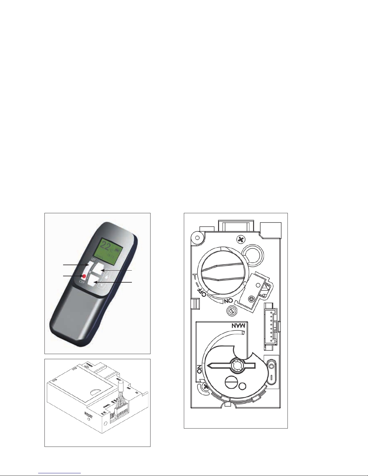
2.2 Remote Control Overview
This Wanders Gas Appliance has been constructed with an advanced remote control system. This consists of three
main parts; Handset (g. 1.1), Receiver (g. 1.2) and Gas Valve with Manual Override (g. 1.3). The Gas control valve
and the Receiver are behind the access door. This is also where the product Data Label is located.
g. 1.2. Remote Receiver
g. 1.1. Remote Handset
A
B
C
D
g. 1.3. Gas Control Valve

6
• The Remote Handset has 4 Buttons; these will perform all operations of the re.
• Always leave the dial on the Gas Control Valve set to "ON", the "MAN" position is only for servicing and
emergency use if the handset is misplaced, or the battery fails.
• With each successful button press of the handset, the receiver will emit an audible signal.
• A toggle switch is present on the Gas Control Valve; this should be put into the "O" position if the appliance is
not operated for a long period (over a week).
• The heat output can be manually adjusted by turning the setting knob on the Gas Control Valve.
2.3 Batteries
Remote Handset:
1 x 9V "PP3" Battery, Quality alkaline recommended
Receiver:
4 x 1.5V "AA", Quality alkaline recommended for maximum life.
An alternative AC Mains Adaptor may be used to power the Receiver instead of the 4 AA batteries. Only an AC
Mains Adapter supplied by Wanders may be used. The Mains Adaptor is plugged into the DC 6V socket on the end
of the receiver.
Note - if the AC Mains Adapter is used, remove the 4 AA's from the Receiver, failure to do so could result in damage
and failure of the Receiver. During a period of power outage, the receiver may be unplugged and batteries returned
to the Receiver.
2.4 Replacing the batteries
Handset:
There is a battery level indicator on the display of the handset. When this gets low remove the cover on the rear of
the handset and replace the battery with another 9V PP3 battery.
Receiver:
Three short audible beeps will sound when the appliance is on to indicate that the batteries in the receiver are
getting low.
When the batteries get very low the appliance will be turned o by the remote control. This will fail to happen if
the power supply is interrupted.
To replace the Receiver batteries, slide the cover o of the top of the receiver and use the ribbon to pull the
batteries out. Replace the batteries with new 1.5V AA's, ensuring that the ribbon is located under the batteries and
that the polarity is correct on all 4 batteries.
Never mix new batteries with old; this will result in the new batteries being emptied very quickly.
When the batteries are replaced, it may be necessary to reset the transmitter code, as detailed in the next section.
2.5 Setting the Transmitter code
Press and hold the RESET button with a sharp object (pen or screwdriver) until you hear two audible beeps. After
the second, longer beep, release the RESET button.
Within the next twenty seconds press the down button (Button D g 1.1) on the remote handset until you hear an
additional long signal conrming the code is set.
2.6 To Ignite the appliance
Note - If this appliance is extinguished or goes out in use for any reason, wait 3 minutes before attempting to
relight the appliance. The Gas Control Valve has an interlock device which will not allow relighting until the 3
minutes have passed.
To be able to use the Remote control Handset (g. 1.1), the rocker switch on the Gas Valve, must be turned "ON"
(the "1" position) and the manual Dial set to the "On" position.

installation, servicing and user instructions manual | GB + IE
7
• Simultaneously press and hold buttons B & C (Star and Large Flame), until a short acoustic beep conrms the
start sequence has begun; release the buttons.
• Continuing signals conrm the ignition is in process.
• Once pilot ignition is conrmed, there will be gas ow and the main burner will ignite.
• Repeat process if pilot ignition fails.
2.7 To Turn the appliance OFF
Press the OFF button (Button B g. 1.1) on the Handset. This will extinguish all Burners including Pilot.
Note: - Repeated presses of the small ame (Button D g. 1.1) will turn the main burner OFF, but will leave the Pilot
alight.
2.8 Adjusting the Flame setting
To increase the ame height; press the large ame button (Button C g. 1.1).
To decrease the ame height; press the small ame button (Button D g. 1.1).
2.9 Using the "Eect" Burner
Note: The solenoid valve will not operate for one minute after Ignition.
The solenoid valve cannot be operated manually. If the battery runs down, the solenoid will remain in its
last operating position.
During normal operation the solenoid will be reset to the ON (Open) when the Gas Valve is switched OFF
via the Handset.
Upon ignition both "Main" and "Eect" burner are ON.
To switch the "Eect" burner OFF, simultaneously press the OFF and Large Flame buttons (buttons B & C g. 1.1).
To switch the "Eect" burner ON, simultaneously press the SET and Large Flame buttons (buttons A & C g. 1.1).
Printed instructions are located on the battery cover on the rear of the handset.
2.10 Setting °C/24 hour or °F/12 hour clock
Simultaneously press OFF and Small Flame buttons (buttons B & D g. 1.1) until display changes from Fahrenheit/12
hour clock to Celsius/24 hour clock and vice versa.
2.11 Setting the Time
The display will ash after either:
• Installing the battery or
• Simultaneously pressing the Large Flame Button and Small Flame Button (buttons C & D g. 1.1)
Press the Large Flame button (button C g. 1.1) to set the hour.
Press the Small Flame button (button D g. 1.1) to set the minutes.
Press OFF (button B g. 1.1) to return to standard operating mode or simply wait and it will return to standard
mode after approximately 15 seconds.
2.12 Cleaning and Maintenance
This appliance should be inspected and serviced once a year by a qualied, competent and registered person.
The inspection and maintenance must at least ensure that the appliance is working correctly and safely. It is
advisable to clean the appliance of any dust and debris before regularly during the heating season and especially
if the appliance has not been used for some time. This can be done with a soft brush and a vacuum cleaner or a
damp cloth and if required a non-abrasive cleaning agent. Do not use corrosive or abrasive substances to clean
the appliance.

8
3. Installation instructions
Before commencing Installation, conrm that the details on the appliance data plate correspond to the local
distribution conditions, gas type and pressure to which the appliance is to be installed.
Ensure that gas supply and supply pipe is capable of delivering the required volume and pressure of gas and is in
accordance with the rules in force.
3.1 Gas Connection
This appliance has a gas inlet connection of Ø 8mm.
3.2 Ventilation
This appliance is a Balanced Flue room sealed appliance, and as such needs no additional ventilation. However an
adequate supply of fresh air to maintain temperatures and a comfortable environment is recommended.
This appliance may be installed in a completely sealed or mechanically ventilated house.
3.3 Appliance Fireplace Installation
• Determine the position required for the appliance.
• Create a gas connection for the appliance in approximately the correct location for the gas controls.
• The gas controls are connected to the Burner of the appliance. These controls need to be located in the
control access box, so an appropriate position for the access box needs to be determined.
• This appliance has fully adjustable legs, these must me set to the desired length before the ue position is
nalised. Fine adjustment of the legs is available via the feet.
• Do not make any adjustments to the appliance, except the leg length.
• The appliance should be tted with a minimum clearance of 150mm from any combustible objects or
materials; this includes any combustible materials used for the replace construction. This clearance distance
can be reduced to 50mm if a Cement Board, of minimum thickness 12mm is used. This Cement Board will act
as a Thermal Break.
• The clearance distance of the Flue from combustibles must not be less than 75mm. This dimension can be
reduced to 25mm as the distance from the underside and the sides of Horizontal Flue runs.
• As this is a room sealed appliance and the appliance stands on appropriate legs, a hearth is not required for
this appliance.
• The Fireplace should be ventilated with openings giving a total free vent area of 200 cm².
• A gap of 50mm should be left all round the appliance.
• If a shelf is to be tted above the replace opening, a gap of 150mm minimum should be left between the
opening and the shelf.See section 3.3.3, Mantel Clearances.
• The brackets supplied may be used for securing the appliance to a rear wall.
3.3.1 Building the Fireplace
• Construct a studwork replace to the desired sizes, minimum sizes are shown in section 3.3.2. Any combustible
material used to construct the Fireplace must not be closer than the minimum dimensions quoted in section
3.3 above. Cement Board of minimum thickness 12mm, can be used as a Thermal Break and can be used
directly against the Frame Face on the appliance.
• Do not use insulation material (or other) to pack the void around or above the appliance.
• Provide ventilation from the replace to the minimum amount quoted in 3.3 above.
• Provide a cut-out for the Control Access Door.
installation, servicing and user instructions manual | GB + IE
9
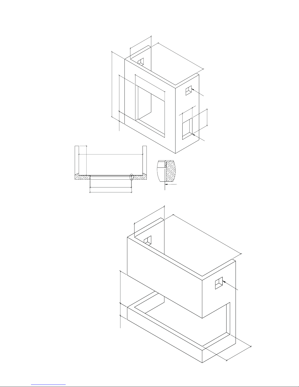
3.3.2 Built-In Fireplace Sizing (assuming a Cement Board Lining is used)
C
F
B
E
D
250
A
175
Free Vent Area
200 cm²
Control
Access
Door
Cut-out
C
A
D
Max plaster
Y
Max. Plaster point
Detail Y
C
E
D
B
G
Free Vent Area
200 cm²
Built in replace sizing
Bay and Room Divider
10
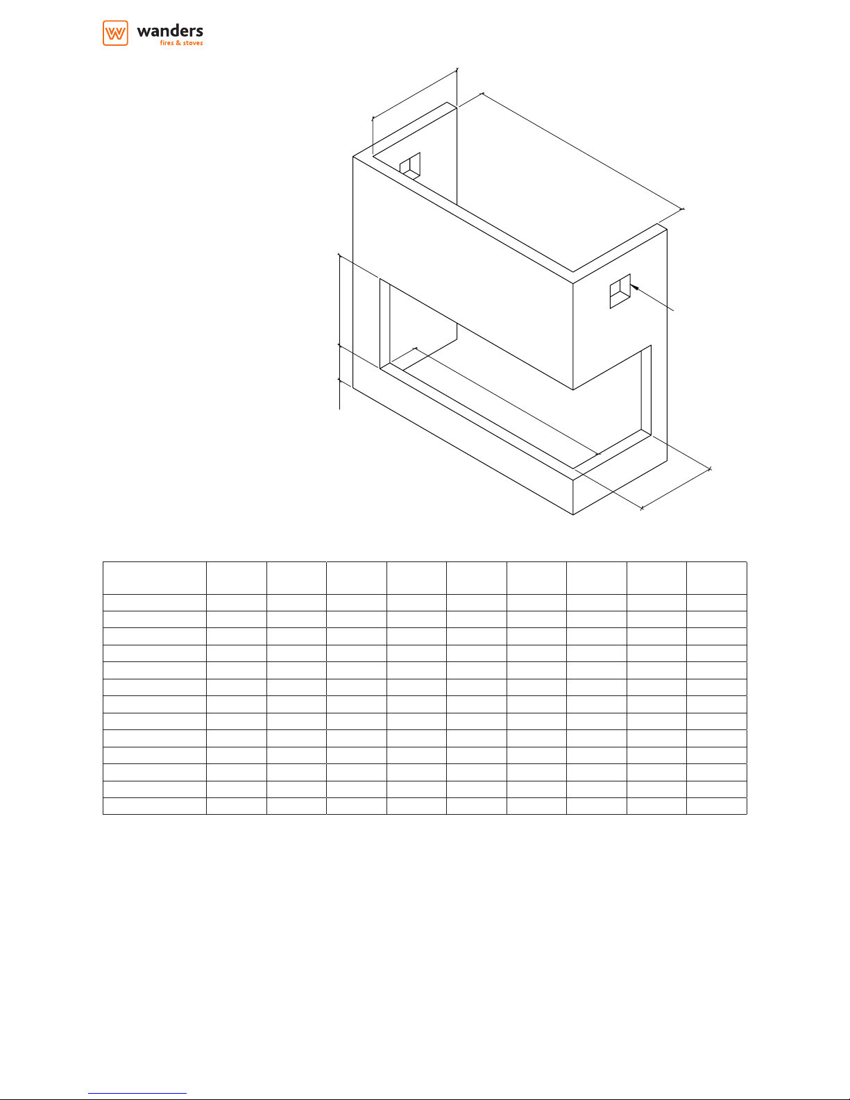
Appliance A min B min C min D min E min F min G min G2 min H min
Danta 500 Front 515 375 650 490 195 700 n/a n/a n/a
Danta 500 Bay n/a 375 555 490 195 700 355 355 n/a
Danta 500 Corner n/a 375 600 490 195 700 355 n/a 515
Danta 800 Front 815 375 850 490 195 700 n/a n/a n/a
Danta 800 Bay n/a 375 855 490 195 700 355 355 n/a
Danta 800 Corner n/a 375 900 490 195 700 355 n/a 815
Danta 1100 Front 1115 375 1150 490 195 700 n/a n/a n/a
Danta 1100 Bay n/a 375 1155 490 195 700 355 355 n/a
Danta 1100 Corner n/a 375 1200 490 195 700 355 n/a 1115
Danta 1100 Front 1415 375 1450 490 195 700 n/a n/a n/a
Danta 1100 Bay n/a 375 1455 490 195 700 355 355 n/a
Danta 1100 Corner n/a 375 1500 490 195 700 355 n/a 1415
Koto 1316 395 1500 425 195 750 n/a n/a n/a
C
E
D
B
G
H
Free Vent Area
200 cm²
Built in replace sizing
Corner appliances

installation, servicing and user instructions manual | GB + IE
11
3.3.4 Mantel Clearances
3.3.4.a Combustible Mantel – Side view
1m (40") Minimum to ceiling
Do not place furniture or any other objects
within 1m (40") of the front of appliance
0 50
(2")
150
(6")
200
(8")
100
(4")
250
(10")
300
(12")
Fireplace Opening
Cement Board
Minimum
12mm (1/2") Thick
0
150 (6")
200 (8")
250 (10")
300 (12")
350 (14")
400 (16")
450 (18")
Mantel Projection
(from face of Cement Board)
Ceiling
Mantel Height
(from Fireplace Opening)
Face of
Finished Wall
 Loading...