

WAM EXTRAC SBB Series, EXTRAC SBB 125C, EXTRAC SBB 150T, EXTRAC SBB 125T, EXTRAC SBB 125S Technical Catalogue [en, de, fr, it]
...Page 1
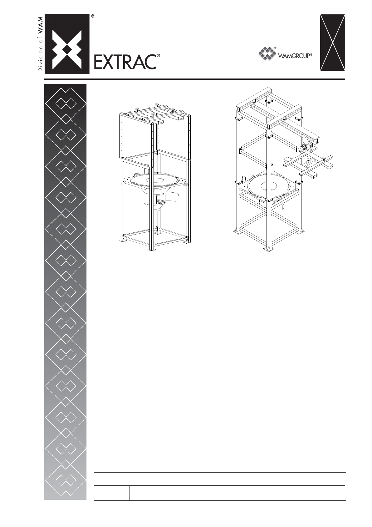
SBB
• FLEXIBLE INTERMEDIATE BULK CONTAINER UNLOADER
• BIG-BAG - ENTLEERST A TION
• VIDE-SACS DE GRANDES DIMENSIONS
• SVUOT A BIG BAG
CAT ALOGUE No. W A.14
ISSUE
A5
All rights reserved © WAMGROUP
CIRCULATION
100
LA TEST UPDA TE
11.07
Page 2
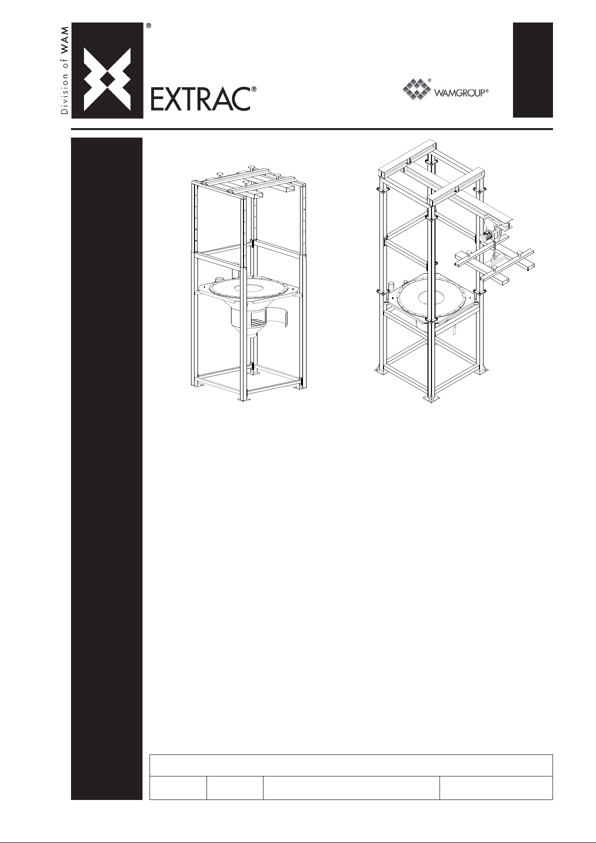
1
• FLEXIBLE INTERMEDIATE BULK CONTAINER UNLOADER
TECHNICAL CA T ALOGUE
• BIG-BAG - ENTLEERSTATION
TECHNISCHER KA T ALOG
• VIDE-SACS DE GRANDES DIMENSIONS
CA TALOGUE TECHNIQUE
• SVUOTA BIG BAG
CATALOGO TECNICO
TECHNICAL CATALOGUE
CAT ALOGUE No. W A.14 T.
SBB
ISSUE
A4
All rights reserved © WAMGROUP
CIRCULATION
100
LA TEST UPDA TE
09.07
Page 3

All the products described in this catalogue are manufactured according to WAM® S.p.A. Quality System
0
procedures.
The Company’s Quality System, certified in July 1994 according to International S tandards UNI EN ISO 9002-94 and
extended to UNI EN ISO 9001-2000 in October, 2002, ensures that the entire production process, starting from the
processing of the order to the technical service after delivery, is carried out in a controlled manner that guarantees
the quality standard of the product.
Alle in diesem Katalog beschriebenen Erzeugnisse werden in Konformität mit dem Qualitätssystem der WAM
S.p.A. hergestellt.
Das im Juli 1994 zertifizierte Qualitätssystem entspricht der Norm UNI EN ISO 9002-94 (im Oktober 2002 auf
UNI EN ISO 9001-2000 erweitert) und gewährleistet dem Kunden eine strenge Qualitätskontrolle in jeder Phase
des Produktionprozesses bis hin zum Kundendienst nach Auslieferung der Ware.
Tous les produits décrits dans ce catalogue ont été réalisé selon les modalités opérationnelles définies Système
de Qualité de WAM® S.p.A.
Le système de Qualité de l’entreprise, certifié au mois de juillet 1994 en conformité aux Normes Internationales UNI
EN ISO 9002-94 et successivement étendu à UNI EN ISO 9001-2000 au mois de octobre 2002, est en mesure
d’assurer que le procédé entier de production, à partir de la formulation de la commande jusqu’au service technique
après la livraison, soit effectué de manière contrôlée et appropriée afin de garantir le standard de qualité du produit.
Tutti i prodotti descritti in questo catalogo sono stati realizzati secondo modalità operative definite Sistema
Qualità di WAM® S.p.A.
Il Sistema Qualità aziendale, certificato dal luglio 1994 in conformità alle Normative Internazionali UNI EN ISO
9002-94 e successivamente esteso alle Normative Internazionali UNI EN ISO 9001-2000 nell’ottobre 2002, è in
grado di assicurare che l’intero processo produttivo, dalla formulazione dell’ordine fino all’assistenza tecnica
successiva alla consegna, venga effettuato in modo controllato ed adeguato a garantire lo standard qualitativo
del prodotto.
®
UNI EN ISO 9001-200
Certifie d Company
This publication cancels and replaces any previous edition and revision.
We reserve the right to implement midifications without notice.
This catalogue cannot be reproduced, even partially, without prior consent.
Diese Veröffentlichung annuliert und ersetzt jeder hergehende Edition oder Revision.
WAM® behält sich das Recht vor, Anderungen ohne vorherige Informationen durchzuführen.
Cette publication annule et remplace toutes les autres précédentes.
La reproduction et la publication partielle ou totale de ce catalogue est interdite sans notre autorisation.
Nous nous réservons le droit d’apporter toutes modifications à nos produits.
Questa pubblicazione annulla e sostituisce ogni precedente edizione o revisione.
Ci riserviamo il diritto di apportare modifiche senza preavviso.
E’ vietata la riproduzione anche parziale senza autorizzazione.
Page 4

1
1
TECHNICAL CA T ALOGUE
SBB
INDEX
INHALTSVERZEICHNIS
INDEX
INDICE
-
09.07
WA.14.INDEX
TECHNISCHER KA TALOG
DESCRIPTION AND USE...................................................
OPERATING CONDITIONS................................................
BASE SUPPL Y: MA TERIALS AND FINISCHING ..................
OPTIONS: MA TERIALS AND FINISCHING..........................
ORDERING CODES..........................................................
FINISHING CARBON STEEL.............................................
FINISHING STAINLESS STEEL AISI 304L .........................
FINISHING STAINLESS STEEL..........................................
MATERIALS AND FINISCHING: NUTS AND BOLTS............
DIMENSION: MODEL T ......................................................
DIMENSION: MODEL C.....................................................
DIMENSION: MODEL S.....................................................
DIMENSION: MODEL M.....................................................
DIMENSION: FIBC LIFTING FRAME...................................
DIMENSION: FOUNDATION PLAN.....................................
OPTIONS: CUTTING SYSTEM...........................................
OPTIONS: PNEUMA TIC ACTIVATORS...............................
OPTIONS: VIBRATOR......................................................
OPTIONS: SEAL - ELECTRIC VIBRA TOR VOL T AGE.........
OPERATION NOISE..........................................................
ACCESSORIES................................................................
APPLICATIONS................................................................
1
CAT ALOGUE TECHNIQUE
DESCRIPTION ET DOMAINE D’UTILISA TION.......................
LIMITES DE EMPLOI..........................................................
COMPOSITION BASIQUE: MA TERIAUX ET FINITION..........
OPTIONS: MA TERIAUX ET FINITION..................................
CODES DE COMMANDE....................................................
FINITION ACIER AU CARBONE..........................................
FINITION AISI 304L............................................................
FINITION ACIER INOX........................................................
MATERIAUX ET FINITION: BOULONNERIE.........................
DIMENSIONS: MODELE T..................................................
DIMENSIONS: MODELE C..................................................
DIMENSIONS: MODELE S..................................................
DIMENSIONS: MODELE M..................................................
DIMENSIONS: CHÂSSIS DE SOULÈVEMENT BIG-BAG ......
DIMENSIONS: PLAN D’ANCRAGE.....................................
OPTIONS: SYSTÈME DE COUPE.........................................
OPTIONS: ACTIVATEURS PNEUMA TIQUES.......................
OPTIONS: VIBRATEUR.....................................................
OPTIONS: JOINT-TENSION DU MOTOVIBRA TEUR.............
BRUYANCE......................................................................
ACCESSOIRES................................................................
APPLICATIONS................................................................
BESCHREIBUNG UND FUNKTION..................................................
EINSATZEINSCHRÄNKUNGEN.........................................................
GRUNDVERRION LIEFERUMFANG: WERKSTOFFE UND FINISH.......
OPTIONEN: WERKSTOFFE UND FINISH...........................................
BESTELLCODE................................................................................
FINISH AUS STAHL..........................................................................
FINISH EDELST AHL 1.4306.............................................................
FINISH EDELSTAHL ........................................................................
WERKSTOFFE UND FINISH:SCHRAUBTEILE....................................
EINBAUMASSE - MODELL T ...........................................................
EINBAUMASSE - MODELL C...........................................................
EINBAUMASSE - MODELL S............................................................
EINBAUMASSE - MODELL M...........................................................
EINBAUMASSE - BIG-BAG - HEBEGESTELL ..............................
EINBAUMASSE -FUNDAMENTPLAN...............................................
OPTIONEN: AUFSCHNEIDEVORRICHTUNG .......................................
OPTIONEN: PNEUMA TISCHE AUSTRAGHILFEN...............................
OPTIONEN: VIBRATION...................................................................
OPTIONEN: DICHTUNG - SPANNUNG DES UNWUCHTMOTORS.......
BETRIEBSGERÄUSHE.....................................................................
ZUBEHÖR.......................................................................................
ANWENDUNGEN..............................................................................
CATALOGO TECNICO
DESCRIZIONE E FUNZIONE D’USO...............................................
LIMITI DI IMPIEGO............................................................................
FORNITURA BASE: MA TERIALI E FINITURE.....................................
OPZIONI: MATERIALI E FINITURE.....................................................
CODICE DI ORDINAZIONE................................................................
FINITURA ACCIAIO AL CARBONIO...................................................
FINITURA AISI 304L........................................................................
FINITURA ACCIAIO INOX.................................................................
MATERIALI E FINITURE: BULLONERIA.............................................
DIMENSIONI: MODELLO T................................................................
DIMENSIONI: MODELLO C...............................................................
DIMENSIONI: MODELLO S................................................................
DIMENSIONI: MODELLO M................................................................
DIMENSIONI: TELAIO DI SOLLEVAMENT O BIG-BAG ........................
DIMENSIONI: PIANTA DI FISSAGGIO................................................
OPZIONI: SISTEMA DI T AGLIO.........................................................
OPZIONI: ATTIV A TORI PNEUMA TICI.................................................
OPZIONI: VIBRATORE.....................................................................
OPZIONI: GUARNIZIONE-TENSIONE MOTOVIBRA TORE..................
RUMOROSITA’.................................................................................
ACCESSORI ...................................................................................
APPLICAZIONI.................................................................................
T.01→ .03
T.01→ .03
.04
.05→ .07
.08
.09
.10→.11
.12
.13
.14
.15→.16
.17→.18
.19→.20
.21
.22→.24
.25→.27
.28
.29→.30
.31
.32
.33
.34→.37
.38→.40
.04
.05→ .07
.08
.09
.10→.11
.12
.13
.14
.15→.16
.17→.18
.19→.20
.21
.22→.24
.25→.27
.28
.29→.30
.31
.32
.33
.34→.37
.38→.40
Page 5

SBB
-
DESCRIPTION AND USE
-
BESCHREIBUNG UND FUNKTION
-
DESCRIPTION ET DOMAINE D’UTILISATION
-
DESCRIZIONE E FUNZIONE D’USO
WA.14 T.
09.07
1
01
The FIBCs, (code SBB) are devices suitable for discharging bulk
bags of different shapes and
sizes.
They are manufactured from shotblasted, painted carbon steel; on
request, they may be supplied in
304 stainless steel, entirely or
only the parts in contact with the
product to prevent its contamination.
The numerous models and sizes of SBB available, together
with the complete range of accessories make these machines
suitable for use in virtually all applications in various industrial
sectors and with different types of
FIBCs: in fact, the hopper, which
can also be supplied alone, is
specially designed for optimising
the bulk material flow.
MACHINE CODE
- SBB
Die Big-Bag Entleerstationen
(Code SBB), sind Vorrichtungen,
die zum Entleeren von Big-Bags
unterschiedlicher Formen und
Abmessungen geeignet sind.
Sie bestehen aus sandgestrahltem und lackierten Stahl. Auf
Anfrage sind sie auch entweder
komplett oder nur in den produktberührenden T eilen aus Edelstahl 1.4301 lieferbar.
Die zahlreichen Modellvarianten
der SBB in Bezug auf Einbaumaße und komplettes Zubehörsortiment machen diese Geräte für
jeden Einsatz in praktisch allen
Industriezweigen sowie für
unterschiedliche Big-Bag-Typen
einsetzbar. Der auch separat
lieferbare Trichter ist für eine
optimierte Fließfähigkeit des
Schüttguts konstruiert.
MASCHINENCODE
- SBB
Les vide BIG-BAG (code SBB)
sont des dispositifs qui servent à
décharger des sacs de différentes
formes et dimensions.
Ils sont réalisés en acier au carbone sablé et peint. Sur demande, ils peuvent être réalisés en
acier inox 304, soit entièrement,
soit uniquement les parties au
contact du produit pour éviter de
le contaminer.
Les nombreuses variantes de
SBB en termes de modèle et dimensions disponibles, associées à une ample gamme d’accessoires, rendent ces machines utilisables pour n’importe
quelle application dans tous les
secteurs industriels et avec différents types de big-bag : en
effet la trémie, qui peut être fournie même séparément, a été conçue spécialement pour optimiser
la fluidité des produits.
CODE MACHINE
- SBB
Gli svuota BIG-BAG (codice SBB)
sono dispositivi idonei a scaricare sacchi di svariate tipologie per
forme e dimensioni.
Sono realizzati in acciaio al carbonio sabbiato e verniciato; su richiesta comunque possono essere realizzati in AISI 304, sia interamente che solo nelle parti a contatto col prodotto per evitare contaminazioni dello stesso.
Le numerose varianti di SBB in
termini di modello e dimensioni
disponibili, unite ad una completa
gamma di accessori, rendono queste macchine utilizzabili per qualsiasi applicazione in tutti i settori
industriali e con diverse tipologie
di big-bag: infatti la tramoggia, che
può essere fornita anche da sola,
è stata accuratamente studiata
per ottimizzare la scorrevolezza
dei materiali.
CODICE MACCHINA
- SBB
MACHINE TYPE
- FLEXIBLE INTERMEDIATE BULK
CONTAINER UNLOADER
USE
- Emptying FIBCs of various sizes containing product in powder or granular form.
ADVANTAGES
- Equipment which can be as-
sembled according to requirements.
- The model with hoist does not
require the use of a forklift
truck.
- The removable frame makes it
possible to empty FIBCs 600
to 1800 mm in height.
- The operator is protected from
falling FIBCs by the four posts
of the frame.
- The FIBC valve can be accessed through the hatch.
- The pneumatic activators optimises emptying of FIBCs.
MASCHINENTYPE
- BIG-BAG ENTLEERSTA TION
BENUTZUNG
- Entleeren von Big-Bags unterschiedlicher Größe mit staubund granulatförmigen Produkten.
VORTEILE
- Leicht und schnell mon-tierba-
res Gerät.
- Die Version mit Flaschenzug
macht den Gabelstapler überflüssig.
- Der herausziehbare Rahmen
ermöglicht das Entleeren von
Big-Bags mit Höhen von 600 bis
1800 mm.
- Der Bediener ist gegen den
eventuellen Absturz des BigBags durch die vier Ständer des
Gestells geschützt.
- Die Klappe ermöglicht den Zugriff zum Ventil des Big-Bags.
- Die pneumatische Austraghilfe
optimiert die Entleerung des
Big-Bags.
TYPE DE MACHINE
- VIDE-SACS GRANDES DIMENSIONS
UTILISATION
- Vidage de GRANDS SACS de
différentes dimensions avec
des produits en poudre ou granulaires.
AVANTAGES
- Machine composée suivant les
exigences.
- La version avec palan n’exige
pas l’utilisation du chariot élévateur.
- Le châssis démontable permet
de vide des sacs d'une hauteur de 600 à 1800 mm.
- Les opérateurs sont protégés
contre la chute des sacs par
quatre montants du châssis.
- Une trappe permet l' accès à la
vanne du BIG BAG.
- Les activateurs pneumatiques
optimisent le vidage du BIG
BAG.
TIPO MACCHINA
- SVUOTA BIG-BAG
FUNZIONE D'USO
- Svuotamento di BIG-BAG di varie dimensioni con prodotti in
polvere o granulari.
VANTAGGI
- Macchina componibile a secon-
da delle esigenze.
- La versione con paranco non richiede l' utilizzo del carrello elevatore.
- Il telaio sfilabile permette di svuotare big bag con altezze da 600
a 1800 mm.
- Gli operatori sono protetti dall'
eventuale caduta dei big bag dai
quattro montanti del telaio.
- Attraverso il portello si accede
alla valvola del BIG BAG .
- Gli attivatori pneumatici ottimizzano lo svuotamento del BIG
BAG.
Page 6

SBB
-
DESCRIPTION AND USE
-
BESCHREIBUNG UND FUNKTION
-
DESCRIPTION ET DOMAINE D’UTILISATION
-
DESCRIZIONE E FUNZIONE D’USO
WA.14 T.
09.07
1
02
MODELS AVAILABLE
MODEL T:
UNLOADING HOPPER
- SBB._.125.T
- SBB._.150.T
Supplied separately, in two sizes, it is carefully designed to
optimize the flowability of materials.
It comprises:
- seals made of material suitable
for the type of use.
- adjustable weight motovi-brator.
- vent pipe with filter bag.
- finger mesh.
- inspection hatch with seal.
- damper supports.
MODEL C:
HOPPER WITH FEET
- SBB._.125.C
- SBB._.150.C
Thanks to its structure, there is
plenty of space for using different systems for loading the
FIBCs.
It comprises:
- a unloading hopper.
- supporting frame made of tubular elements having suitable
size and thickness to ensure
sturdiness and solidity.
- cross with pegs for hooking
FIBC harness, lifting hooks and
tubular elements for lift truck
forks
LIEFERBARE MODELLE
MODELL T:
AUSLAUFTRICHTER
- SBB._.125.T
- SBB._.150.T
Wird separat geliefert; in zwei
Größen erhältlich; ausgelegt, um
optimalen Materialfluß zu gewährleisten.
Besteht aus:
- Dichtung aus dem Einsatz angepaßten Material.
- Vibrationsmotor mit einstellbaren Unwuchtmassen.
- Entlüftungsstutzen mit Filtersack.
- Schutzgitter.
- Inspektionsklappe mit Dichtung.
- Schwingungsdämpfende Träger.
MODELL C:
TRICHTER AUF STANDBEINEN
- SBB._.125.C
- SBB._.150.C
Läßt dank der besonderen Konstruktion viel Platz für Big-BagHandlingsyteme.
Besteht aus:
- Auslauftrichter .
- Robustes und solides Traggestell aus Rohren.
- Kreuzteil mit Stiften zum Einhaken der Big-Bag-Gurte, Hubhaken und Rohre für die Gabeln
des Staplers.
MODELES DISPONIBLES
MODELE T :
TREMIE DE DÉCHARGEMENT
- SBB._.125.T
- SBB._.150.T
Fournie même seule, en deux dimensions, elle a été étudiée spécialement pour optimiser l' écoulement des produits.
Elle est composée de:
- joint en matière appropriée au
secteur d' utilisation.
- motovibrateur à masses réglables.
- tube d' évent à manchon filtrant.
- grille de sécurité.
- trappe de visite avec joint.
- supports absorbe vibrations.
MODELE C :
TREMIE AVEC PIEDS
- SBB._.125.C
- SBB._.150.C
Grâce à sa conformation il laisse un espace ample à l'utilisateur des systèmes les plus variés de chargement du BIG BAG .
Composé de:
- trémie de dechargement.
- châssis de soutien réalisé en
tubulaire aux dimensions et
épaisseurs garantissant la robustesse et la solidité de la
structure.
- croisillon à picots d' accrochage des bretelles BIG BAG, crochet de soulèvement et tubulaires pour fourches de chariot élévateur.
MODELLI DISPONIBILI
MODELLO T :
TRAMOGGIA DI SCARICO
- SBB._.125.T
- SBB._.150.T
Fornita anche da sola, in due dimensioni, è stata accuratamente studiata per ottimizzare la scorrevolezza dei materiali.
E' composta da:
- guarnizione di tenuta in materiale idoneo al settore di impiego.
- motovibratore a masse regolabili.
- tubo sfiato aria con manica filtrante.
- griglia di sicurezza.
- portello di ispezione con relativa guarnizione.
- supporti antivibranti.
MODELLO C:
TRAMOGGIA CON PIEDI
- SBB._.125.C
- SBB._.150.C
Grazie alla sua conformazione lascia ampio spazio all' utilizzo dei
più svariati sistemi di carico del
BIG BAG.
Composto da:
- tramoggia di scarico.
- telaio di sostegno realizzato in
tubolari di dimensioni e spessori tali da garantire robustezza e
solidità.
- crociera con pioli di aggancio
bretelle BIG BAG , gancio di sollevamento e tubolari per forche
carrello elevatore.
MODEL S:
HOPPER WITH REMOVABLE
FRAME
- SBB._.125.S
- SBB._.150.S
Athough it is identical as regards
design and use, the difference
lies in the size of the FIBCs
which can be accepted.
These comprise:
- a unloading hopper.
- supporting tubular frame having size and thickness suitable
to guarantee sturdiness and
solidity.
- removable frame which makes
it possible to adapt the Unloader for use with FIBCs of different heights.
- cross with pegs for hooking
FIBC harness, lifting hooks and
tubular elements for lift truck
forks
MODELL S:
TRICHTER MIT HERAUSZIEHBAREM GESTELL
- SBB._.125.S
- SBB._.150.S
Im Aufbau und im Einsatz identisch, jedoch geeignet für größere Big-Bags.
Besteht aus:
- Auslauftrichter.
- Rohrtragegestell in robu-ster
Bauweise.
- Herausziehbarer Rahmen zur
Anpassung des Geräts an
verschiedene Big-Bag-Größen.
- Kreuzteil mit Stiften zum Einhaken der Big-Bag-Gurte, Hubhaken und Rohre für die Gabeln
des Staplers.
MODELE S :
TREMIE AVEC CHASSIS AMOVIBLE
- SBB._.125.S
- SBB._.150.S
Bien qu' étant identiques par
composition et utilisation ils se
différencient par les dimensions
des SACS "BIG BAG" qu'ils peuvent accepter.
Ils sont composés de:
- trémie de dechargement.
- châssis réalisé en tubulaire aux
dimensions et épaisseurs garantissant robustesse et solidité.
- châssis démontable pour permettre d' adapter la machine
aux différentes hauteurs des
BIG BAG.
- croisillon à picots d' accrochage des bretelles BIG BAG, crochet de soulèvement et tubulaires pour fourches de chariot élévateur.
MODELLO S:
TRAMOGGIA CON TELAIO SFILABILE
- SBB._.125.S
- SBB._.150.S
Pur essendo identici per composizione e funzione d' uso si differenziano per le dimensioni dei
BIG BAG che possono accettare.
Sono composti da:
- tramoggia di scarico.
- telaio di sostegno realizzato in
tubolari di dimensioni e spessori tali da garantire robustezza e solidità.
- telaio sfilabile per consentire di
adattare la macchina alle diverse altezze dei BIG BAG.
- crociera con pioli di aggancio
bretelle BIG BAG , gancio di sollevamento e tubolari per forche
carrello elevatore.
Page 7

SBB
-
DESCRIPTION AND USE
-
BESCHREIBUNG UND FUNKTION
-
DESCRIPTION ET DOMAINE D’UTILISATION
-
DESCRIZIONE E FUNZIONE D’USO
WA.14 T.
09.07
1
03
MODEL M:
FRAME WITH MONORAIL
- SBB._.125.M
The special feature of this equipment lies in the fact that it does
not require the use of a fork lift
truck for external loading of
FIBCs, as it is designed for use
with its own hoist (not supplied)
which makes it possible to operate
independently during the various
phases.
The equipment comprises:
- a unloading hopper.
- a supporting frame made of
suitably sized tubular elements
thick enough to guarantee the
required sturdiness and solidity.
- a monorail for the hoist (hoist
excluded).
- cross with pegs for hooking
the FIBC harness, lifting hooks
and tubular elements for using
a lift truck if necessary for handling FIBCs.
ACCESSORIES
- Hopper seal made of foodgrade material.
MODELL M:
GESTELL MIT MONOSCHIENE
- SBB._.125.M
Die Besonderheit dieses Geräts
besteht darin, daß es zum Aufladen des Big-Bags keinen Gabelstapler benötigt, weil das
Gerät für die Installation einer
eigenen Seilwinde ausgelegt ist
(gehört nicht zum Lieferumfang),
was in den verschiedenen
Arbeitsphasen ein Höchstmaß an
Autonomie bedeutet.
Besteht aus:
- Auslauf trichter.
- Rohrtragegestell in robuster
Bauweise.
- Monoschiene für Seilwinde (Flaschenzug ausgenommen).
- Kreuzteil mit Stiften zum Einhaken der Big-Bag-Gurte, Haken
zum Heben und Rohre für die
eventuelle Benutzung eines
Gabelstaplers zum Handling der
Big-Bags.
ZUBEHÖR
- Trichterdichtung aus nahrungsmitteltauglichem Material.
MODELE M :
CHASSIS AVEC MONORAIL
- SBB._.125.M
Sa particularité est celle de ne
pas exiger l' utilisation d'un chariot élévateur pour le chargement
du BIG BAG extérieur car il est
prévu pour être équipé d' un treuil
(non fourni) qui permet une
meilleure autonomie dans les différentes phases de travail.
Composé de:
- trémie de dechargement.
- châssis réalisé en tubulaire aux
dimensions et épaisseurs garantissant robustesse et solidité.
- monorail pour palan (palan exclu).
- croisillon à picots d'accrochage des bretelles BIG BAG, crochet de soulèvement et tubulaires pour l'utilisation éventuelle d'un chariot élévateur pendant les phases de manutention des BIG BAG.
ACCESSOIRES
- Joint trémie en matière indiquée
pour le secteur alimentaire
MODELLO M:
TELAIO CON MONOROTAIA
- SBB._.125.M
La sua particolarità è quella di non
richiedere l' uso di un carrello elevatore per il carico BIG BAG esterno in quanto è predisposto per l'
installazione di un proprio verricello (non fornito) che permette la più
completa autonomia nelle varie fasi
di lavoro.
Composto da:
- tramoggia si scarico.
- telaio di sostegno realizzato in
tubolari di dimensioni e spessori tali da garantire robustezza e
solidità.
- monorotaia per paranco (paranco escluso).
- crociera con pioli di aggancio
bretelle BIG BAG , gancio di sollevamento e tubolari per l' eventuale utilizzo di un carrello elevatore durante le fasi di movimentazioni dei BIG BAG.
ACCESSORI
- Guarnizione tramoggia in materiale idoneo al settore alimentare
- Pneumatic activators
Materials featuring poor flowability do not flow out of the
FIBC easily. It is therefore necessary to use pneumatic activators. These devices act directly at the bottom of the FIBC,
causing lifting and lowering of
the opposite corners to stimulate the flow of material compacted at the bottom.
The gradual movement of the
activators makes the FIBC assume a "V" shape, to eliminate
the deadlock points.
For more information, see Technical Catalogue - Maintenance
KSC.
- Cutting device
It is used for cutting FIBCs without valves which cannot be recycled after emptying.
- Hose connector kit available in
black or white food- grade rubber.
- Round or square flange for
hopper.
- Raised feet for lifting the entire
structure.
- Mechanical limit stop for signalling door open status.
- Manual gate valve at outlet.
- Pneumatische Austraghilfe Materialien, die nur schwach rieselfähig sind und nur schwer
aus dem Big-Bag ausgetragen
werden können, verlangen den
Einsatz pneumatischer Austraghilfen. Diese wirken direkt
auf den unteren Teil des BigBags und bewegen die gegenüberliegenden Sackkanten aufund abwärts, damit das im unteren Bereich verdichtete Material abläuft.
Das ständige Ausfahren der
Austraghilfe dient dazu, daß
der Big-Bag eine V-förmige
Gestalt annimmt, wodurch T oträume beseitigt werden.
Weitere Informationen siehe
T echnischer Katalog - Einbau und
Wartungsanleitung KSC.
- Schneidevorrichtung
Hat die Funktion, Einwegsäcke
ohne Ventil aufzuschneiden.
- Montagesatz für flexible Verbindung, erhältlich in schwarzem oder weißem, nahrungsmittelechtem Kautschuk.
- Rund- oder Vierkantflansche
für Trichter.
- Füße zum Höherstellen der
kompletten Vorrichtung.
- Mechanischer Endschalter für
Meldung Klappe offen.
- Handschieber am Auslauf.
.
- Activateurs pneumatiques.
Les matières peu fluides ne
sortent pas facilement des
sacs. Il est donc nécessaire
d'appliquer des activateurs
pneumatiques. Ils agissent directement sur le fond des "big
bag" en déterminant un rehaussement ou un abaissement des
angles opposés de manière à
stimuler la sortie du produit
compacte sur le fond.
Le mouvement progressif des
activateurs fait prendre une
forme en "V" au big bag de
manière à éliminer les points
morts.
Pour plus d'informations voir Catolgue Techinique - Utilisation et
Entertien KSC.
- Système de coupe.
Sa fonction est de couper les
gros sacs sans valve, qui ne
sont pas récupérés après vidange.
- Kit de liaison flexible disponible
en caoutchouc noir ou blanc
pour secteur alimentaire.
- Brides rondes ou carrées pour
la trémie.
- Pieds de rehausse pour le soulèvement de toute la structure.
-- Fin de course mécanique pour
signaler l’ouverture du portillon.
- Vanne manuelle de déchargement.
- Attivatori pneumatici.
I materiali poco scorrevoli non
escono facilmente dai big bag
pertanto si rende necessario
applicare degli attivatori pneumatici. Questi agiscono direttamente sul fondo dei big bag
determinando un innalzamento
e un abbassamento degli spigoli opposti in modo da stimolare la fuoriuscita del materiale
compattato sul fondo.
La progressiva escursione degli attivatori fa si che il big bag
assume la forma a "V" in modo
da eliminare i punti morti.
Per ulteriori informazioni consultare il relativo Catalogo Tecnico Uso e Manutenzione KSC.
- Sistema di taglio.
Ha la funzione di tagliare BIG
BAG senza valvola, monouso.
- Kit collegamento flessibile disponibile in gomma nera o bianca per settore alimentare.
- Flange tonde o quadre per tramoggia.
- Piedi di rialzo per il sollevamento di tutta la struttura.
- Fine corsa meccanico per segnalazioni apertura portello.
- Serranda manuale allo scarico.
Page 8

SBB
-
OPERATING CONDITIONS
-
EINSATZEINSCHRÄNKUNGEN
-
LIMITES D’EMPLOI
-
LIMITI DI IMPIEGO
WA.14 T.
09.07
1
04
The SBB-type FIBCs are designed
and constructed for carrying out
their function in compliance with
the following limits of use:
Maximum operating temperature:
+40°C in continuous mode
Minimum operating temperature:
-20°C
Height of FIBC:
- Min. 600mm
- Max. 2000mm
(for models S and M)
- Any
(for models T and C)
USE
- The FIBC discharger is NOT
designed for operating in potentially explosive atmospheres or with materials that
could be hazardous by contact
and/or inhalation, or else dangerous from a bacteriological
or viral viewpoint.
Die Big-Bag Entleerstationen
(SBB) wurden entwickelt, um ihre
Funktion unter Beachtung der folgenden Einsatzgrenzen auszuführen:
Max. Betriebstemperatur:
+40°C bei Dauerbetrieb
Tiefste Betriebstemperatur:
-20°C
Höhe der Big-Bag:
- Min. 600 mm
- Max. 2000 mm
(für Modelle S und M)
- Jede beliebige
(für Modelle T und C)
GEBRAUCHSANGABEN
- Die Big-Bag Entleerstation ist
NICHT zum Einsatz in explosionsgefährdeten Bereichen
oder zur Arbeit mit Materialien
bestimmt, die bei Berührung
und/oder Einatmen schädlich
sind oder die unter bakteriologi-schen oder virologischen
Ge-sichtspunkten gefährlich
sind.
Les vide BIG BAG (SBB) ont été
conçus et projetés pour assurer
leur fonction d’utilisation dans le
respect des limites d’emploi suivantes :
Température maximum de
travail :
+40°C en continu
Température minimum de
travail :
-20°C
Hauteur des BIG-BAG:
- Min. 600 mm
- Max. 2000 mm
(pour modèles S et M)
- Quelconque
(pour modèles T et C)
MODES D’EMPLOI
- Le vide BIG-BAG N’A PAS été
conçu pour travailler dans des
atmosphères explosibles, ni
avec des matières nocives au
contact ou à l’inhalation, ou
encore dangereuses du point
de vue bactériologique et viral :
Gli svuota BIG-BAG (SBB) sono
stati studiati e progettati per assolvere alla loro funzione d’uso
nel rispetto dei seguenti limiti di
impiego:
Temperatura
massima di lavoro:
+40°C in continuo
Temperatura
minima di lavoro:
-20°C
Altezza dei BIG-BAG:
- Min. 600 mm
- Max. 2000 mm
(per modelli S e M)
- Qualsiasi
(per modelli T e C)
INDICAZIONI PER L’USO
- Lo svuota BIG-BAG NON è statoprogettato per operare in atmosfere potenzialmente esplosive o con materiali nocivi al
contatto e/o inalazione, oppure pericolosi dal punto di vista
batteriologico e virale.
If the machine has to cater
for similar requirements,
please contact the manufacturer.
Wenn die Maschinen unter
solchen Bedingungen zum
Einsatz kommen sollen, ist
es vorgeschrieben, Kontakt
mit dem Hersteller aufzunehmen.
Quand la machine doit être
utilisée dans ces conditions,
il faut contacter le fabricant.
Quando la macchina deve
assolvere a queste esigenze è d’obbligo contattare il
Costruttore.
Page 9
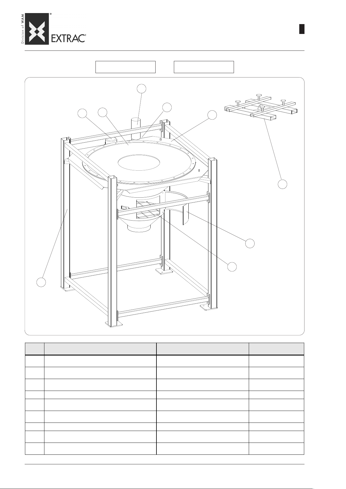
-
BASE SUPPL Y : MA TERIALS AND FINISHING
-
SBB
GRUNDVERRION LIEFERUMFANG: WERKSTOFFE UND FINISH
-
COMPOSITION BASIQUE: MATERIAUX ET FINITION
-
FORNITURA BASE: MA TERIALI E FINITURE
SBB._.125.C SBB._.150.C
07
WA.14 T.
09.07
1
05
01
02
05
•
•
06
•
•
•
•
09
•
•
•
03
04
08
ITEM
POS.
Motovibrator - Vibrationsmotor
01
Motovibrateur - Motovibratore
Seal - Dichtung
02
Joint - Guarnizione
Access door - Inspektionsklappe
03
Porte - Boccaporto
04
Grille - Gi tter - Grille - Griglia AISI 304 Vibrating hopper - Vibrationstrichter
05
Trèmie vibrante - Tramoggia vibrante
Venting pipe - Entlüftungsrohr
06
Tube èvent air - Tubo sfiato aria
07
Filter bag - Fi ltersack - Manchon filtran t - M ani ca filtrante Felt - Filz - Feutre - Feltro -
Frame - Traggestell
08
Châssis de soutien - Telaio di sostegno
Lifting cross - Kreuzstück zum Heben
09
Croisillon de soulèvement - Crociera di sollevamento
DESCRIPTION - BENENNUNG
DESIGNATION - DESCRIZIONE
MAT ERIAL - WERKSTOFF
MATER IAU - MATERIALE
-RAL 2004
SBR
Carbon steel - Normstahl
Acier au carbone - Acciaio al carbonio
Carbon steel - Normstahl
Acier au carbone - Acciaio al carbonio
Carbon steel - Normstahl
Acier au carbone - Acciaio al carbonio
Carbon steel - Normstahl
Acier au carbone - Acciaio al carbonio
Carbon steel - Normstahl
Acier au carbone - Acciaio al carbonio
FINISHING - FINISH
FINITION - FINITUR A
black - schwarze Farbe
co ul eur noi r - colore nero
RAL 7001
RAL 7001
RAL 7001
RAL 7001
RAL 7001
Page 10
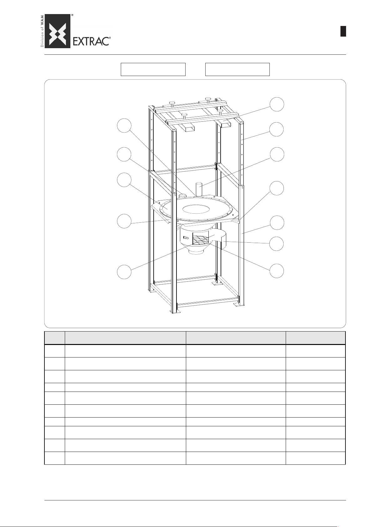
-
BASE SUPPL Y : MA TERIALS AND FINISHING
-
SBB
GRUNDVERRION LIEFERUMFANG: WERKSTOFFE UND FINISH
-
COMPOSITION BASIQUE: MATERIAUX ET FINITION
-
FORNITURA BASE: MA TERIALI E FINITURE
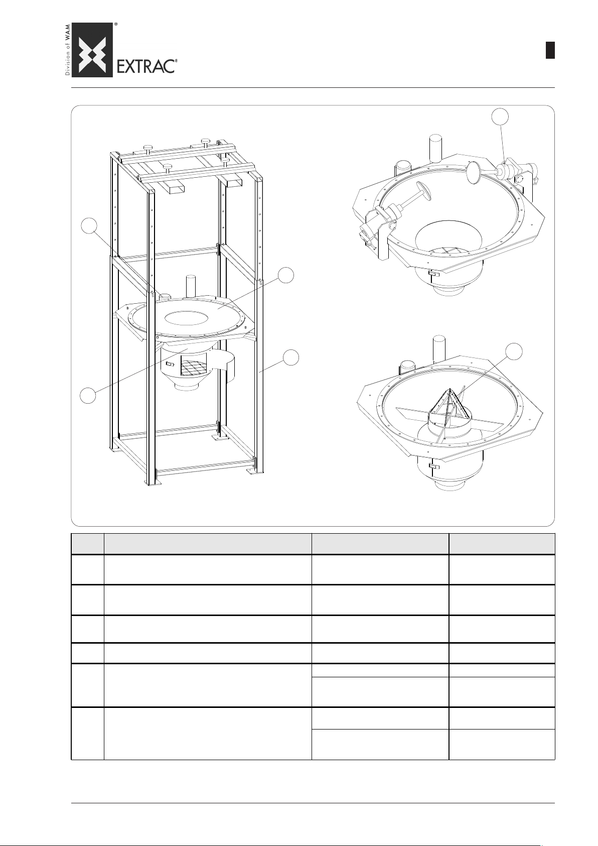
SBB._.125.S SBB._.150.S
10
WA.14 T.
09.07
1
06
06
01
02
05
12
•
09
•
07
•
•
•
05
•
•
•
•
•
08
•
•
03
04
ITEM
POS.
Motovibrator - Vi brationsmotor
01
Motovibrateur - Motovibratore
Seal - Dichtung
02
Joint - Guarnizione
Access door - Inspektionsklappe
03
Porte - Boccaporto
04
Grille - Gi tte r - Grille - Griglia AISI 304 -
Vibrating hopper - Vibrationstrichter
05
Trèmie vibrante - Tramoggia vibrante
Venting pipe - Entlüftungsrohr
06
Tube èvent air - Tubo sfiato aria
07
Filter bag - Fi l tersack - Manchon filtra nt - M anica filtrante Felt - Filz - Feutre - Feltro -
Frame - Traggestell
08
Châssis de soutien - Telaio di sostegno
Monorail - Einschienenbahn
09
Monorail - Telaio sfilabile
Lifting cross - Kreuzstück zum Heben
10
Croisillon de soulèvement - Crociera di sollevamento
DESCRIPTION - BENENNUNG
DESIGNATION - DESCRIZIONE
MATERIAL - WERKSTOFF
MAT ERIAU - MATERIALE
- RAL 2004
SBR
Carbon steel - Normstahl
Acier au carbone - Acciaio al carbonio
Carbon steel - Normstahl
Acier au carbone - Acciaio al carbonio
Carbon steel - Normstahl
Acier au carbone - Acciaio al carbonio
Carbon steel - Normstahl
Acier au carbone - Acciaio al carbonio
Carbon steel - Normstahl
Acier au carbone - Acciaio al carbonio
Carbon steel - Normstahl
Acier au carbone - Acciaio al carbonio
FINISHING - FINISH
FINITION - FINITURA
black - schwarze Farbe
couleur no ir - colore nero
RAL 7001
RAL 7001
RAL 7001
RAL 7001
RAL 7001
RAL 7001
Page 11
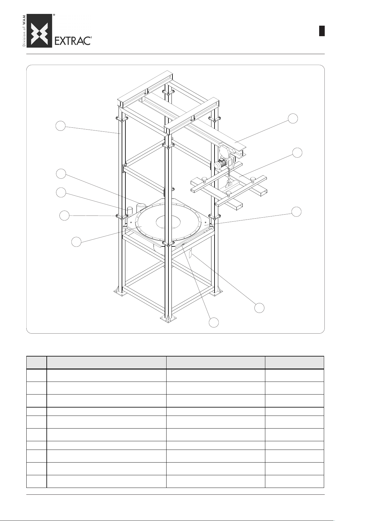
08
SBB
-
BASE SUPPL Y : MA TERIALS AND FINISHING
-
GRUNDVERRION LIEFERUMFANG: WERKSTOFFE UND FINISH
-
COMPOSITION BASIQUE: MATERIAUX ET FINITION
-
FORNITURA BASE: MA TERIALI E FINITURE
•
•
WA.14 T.
09
10
09.07
1
07
01
07
06
02
•
•
•
•
•
•
05
•
•
03
04
ITEM
POS.
Motovibrator - Vibrationsmotor
01
Motovibrateur - Motovibratore
Seal - Dichtung
02
Joint - Guarnizione
Access door - Inspektionsklappe
03
Porte - Boccaporto
04
Grille - Gi tter - Grille - Griglia AISI 304 Vibrating hopper - Vibrationstrichter
05
Trèmie vibrante - Tramoggia vibrante
Venting pipe - Entlüftungsrohr
06
Tube èvent air - Tubo sfiato aria
07
Filter bag - Fi ltersack - Manchon filtrant - M anica filtrante Feltro - Feltro - Feltro - Feltro Frame - Traggestell
08
Châssis de soutien - Telaio di sostegno
Monorail - Einschienenbahn
09
Monorail - Telaio sfilabile
Lifting cross - Kreuzstück zum Heben
10
Croisillon de soulèvement - Crociera di sollevamento
DESCRIPTION - BENENNUNG
DESIGNATION - DESCRIZIONE
MAT ERIAL - WERKSTOFF
MATERIAU - MATERIALE
- RAL 2004
SBR
Carbon steel - Normstahl
Aci er au carbone - Acciaio al carbonio
Carbon steel - Normstahl
Aci er au carbone - Acciaio al carbonio
Carbon steel - Normstahl
Aci er au carbone - Acciaio al carbonio
Carbon steel - Normstahl
Aci er au carbone - Acciaio al carbonio
Carbon steel - Normstahl
Aci er au carbone - Acciaio al carbonio
Carbon steel - Normstahl
Aci er au carbone - Acciaio al carbonio
FINISHING - FINISH
FINITION - FINITURA
black - schwarze Farbe
co ul eur noi r - colore nero
RAL 7001
RAL 7001
RAL 7001
RAL 7001
RAL 7001
RAL 7001
Page 12
04
WA.14 T.
09.07
1
08
SBB
-
OPTIONS: MATERIALS AND FINISHING
-
OPTIONEN: WERKSTOFFE UND FINISH
-
OPTIONS: MATERIAUX ET FINITION
-
OPZIONI: MATERIALI E FINITURE
05
•
03
•
•
•
02
ITEM
POS.
Supporting frame - Taggestell
01
Châssis de soutien - Telaio di sostegno
Vibrating hopper - Vibrationstrichter
02
Trèmie vibrante - Tramoggia vibrante
Seal - Dichtung
03
Joint - Guarnizione
Larger vibrator - Verstä rk ter Unwuchtmo to r
04
Vibrateur majoré - Vibratore maggiorato
Pneumatic activators Kit - Bausatz pneumatische Austraghilfen
05
Kit actionneurs pneumatiques - Kit attivatori pneumatici
Cutting Kit - Aufschneidvorrichtung
06
Kit de coupe - Kit di taglio
DESCRIPTION - BENENNUNG
DESIGNATION - DESCRI ZI ONE
01
06
•
•
MATERIAL - WERKSTOFF
MATERIAU - MATERIALE
304L St.st. - Edelstahl 1.4401
Inox 304L - AISI 304L
304L St.st. - Edelstahl 1.4401
Inox 304L - AISI 304L
food-grade - lebensmitteltauglich
Carbon steel - Stahl - Aci e r - Ferro RAL 7001
304L St.st. - Edelstahl 1.4401
304L St.st. - Edelstahl 1.4401
NBR
alimentaire - alimentare
- RAL 2004
Inox 304L - AISI 304L
Carbon steel - Stahl
Aci er - Ferro
Inox 304L - AISI 304L
FINISHING - FINISH
FINITION - FINITURA
Mesc buffing - Schliff
Satin. - Satinatura
80 (4/4/IV*)
Mesc buffing - Schliff
Satin. - Satinatura
80 (4/4/IV*)
white - we iß e F arbe
couleur blanc - colore bianco
Mesc buffing - Schliff
Satin. - Satinatura
80 (4/4/IV*)
RAL 7001
Mesc buffing - Schliff
Satin. - Satinatura
80 (4/4/IV*)
*Accordin to UNI-EN 10088 (1997)/AISI (1974) / DIN 17440 (1985) - *Gemaß UNI-EN 10088 (1997)/AISI (1974) / DIN 17440 (1985)
*Selon UNI-EN 10088 (1997)/AISI (1974) / DIN 17440 (1985) - *Secondo UNI-EN 10088 (1997)/AISI (1974) / DIN 17440 (1985)
Page 13
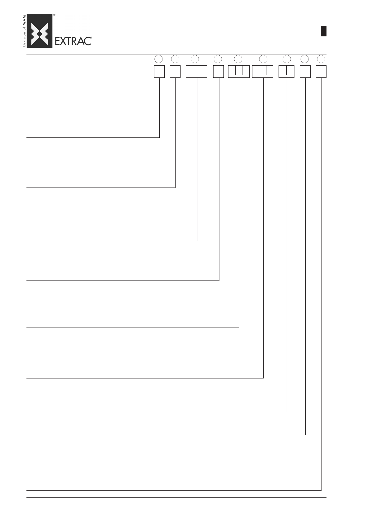
SBB
-
ORDERING CODE
-
BESTELLCODE
-
CODE DE COMMANDE
-
CODICE DI ORDINAZIONE
WA.14 T.
09.07
1
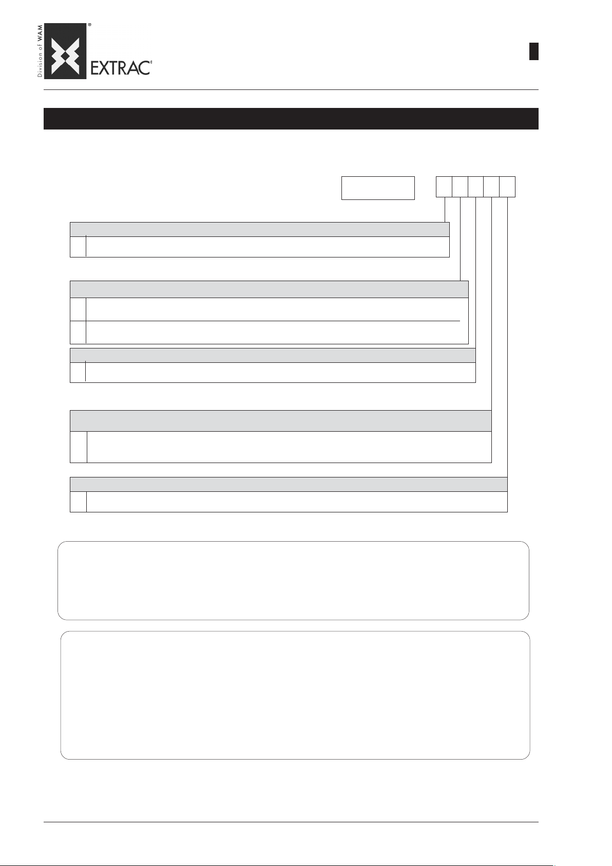
09
1 2 3 4
SBB
HOPPER AND FRAME MATERIAL
WERKSTOFF TRICHTER UND GESTELL
MATÉRIAU TREMIE ET CHASSIS
MATERIALE TRAMOGGIA E TELAIO
1= Fe (St) Standard
2= Parts in contact AISI 304 - medienberührende T eile aus Edelstahl 1.4301
Parties en contact AISI 304 - Parti a contatto AISI 304
4= Entirely made of - Komplett aus
Emtièrement en - Completamente in 304 st. st. - Edelstahl 1.4306- AISI 304
COUNTER-FLANGE AND BOLTS MA TERIAL
WERKSTOFF GEGENFLANSCH UND SCHRAUBTEILE
MA TERIAU CONTRE-BRIDE ET BOULONS
MATERIALE CONTROFLANGIA E BULLONERIA
1 = Fe (St) Standard
2 = AISI 304 (1.4306)
HOPPER DIAMETER - TRICHTERDURCHMESSER
DIAMÈTRE TRÉMIE - DIAMETRO TRAMOGGIA
125 = 1250 mm
150 = 1500 mm
FRAME TYPE - TYP TRAGGESTELL - TYPE DE CHÂSSIS - TIPO TELAIO
5 6
7 8 9
T =
WITHOUT - OHNE - SANS - SENZA (only hopper - nur Trichter - seulement trémie - solo tramoggia)
C = SHORT - KURZ - COURT - CORTO
S = WITH HEIGHT EXT. - MIT HÖHENVERST. - A VEC DÉFILABLES - CON SFILABILI
M = WITH HOIST RAIL - MIT KETTENZUGSCHIENE
AVEC MONORAIL POUR PALAN - CON MONOROTAIA PER P ARANCO
CUTTING KIT “KT” - AUFSCHNEIDEVORRICHTUNG “KT”
SYSTÈME DE COUPE “KT” - KIT TAGLIO “KT”
+++ = WITHOUT - OHNE - SANS - SENZA
KT1 = Kit Fe (St)
KT2 = Kit AISI 304
KIT PNEUMATIC ACTIVATORS - KIT PNEUMATISCHE AUSTRAGHILFE
KIT ACTIVATEURS PNEUMATIQUES - KIT A TTIVAT ORI PNEUMA TICI
+++ = WITHOUT - OHNE - SANS - SENZA
KSP = only predisposition - nur vorgesehen für - seulement prédisposition - solo predisposizione
KSC = WITHOUT ELECTRIC-PNEUMATIC PANEL - OHNE ELEKTROPNEUMATIKSTEUERUNG
SANS ARMOIRE ÉLECTRIQUE-PNEUMATIQUE - SENZA QUADRO ELETTROPNEUMA TICO
KSQ = WITH ELECTRIC-PNEUMATIC PANEL - MIT ELEKTROPNEUMA TIKSTEUERUNG
AVEC ARMOIRE ÉLECTRIQUE-PNEUMA TIQUE - CON QUADRO ELETTROPNEUMATICO
VIBRATOR - VIBRATIONSMOTOR - VIBRATEUR - VIBRATORE
++ = NONE - KEINER - AUCUN - NESSUNO
10 = VIBRATOR - VIBRATIONSMOTOR - VIBRATEUR - VIBRA TORE: 0.10 kW
18 = VIBRATOR - VIBRATIONSMOTOR - VIBRATEUR - VIBRAT ORE: 0.18 kW (STD SBB150)
SEAL - DICHTUNG - JOINT - GUARNIZIONE
N = BLACK RUBBER - GUMMI SCHWARZ - CAOUTCHOUC NOIR - GOMMA NERA (SBR)
B = WHITE FOOD-GRADE - GUMMI WEISS NAHRUNGSM. - CAOUTCHOUC BLANC POUR ALIMENT . - GOMMA BIANCA USO ALIMEN. (NBR)
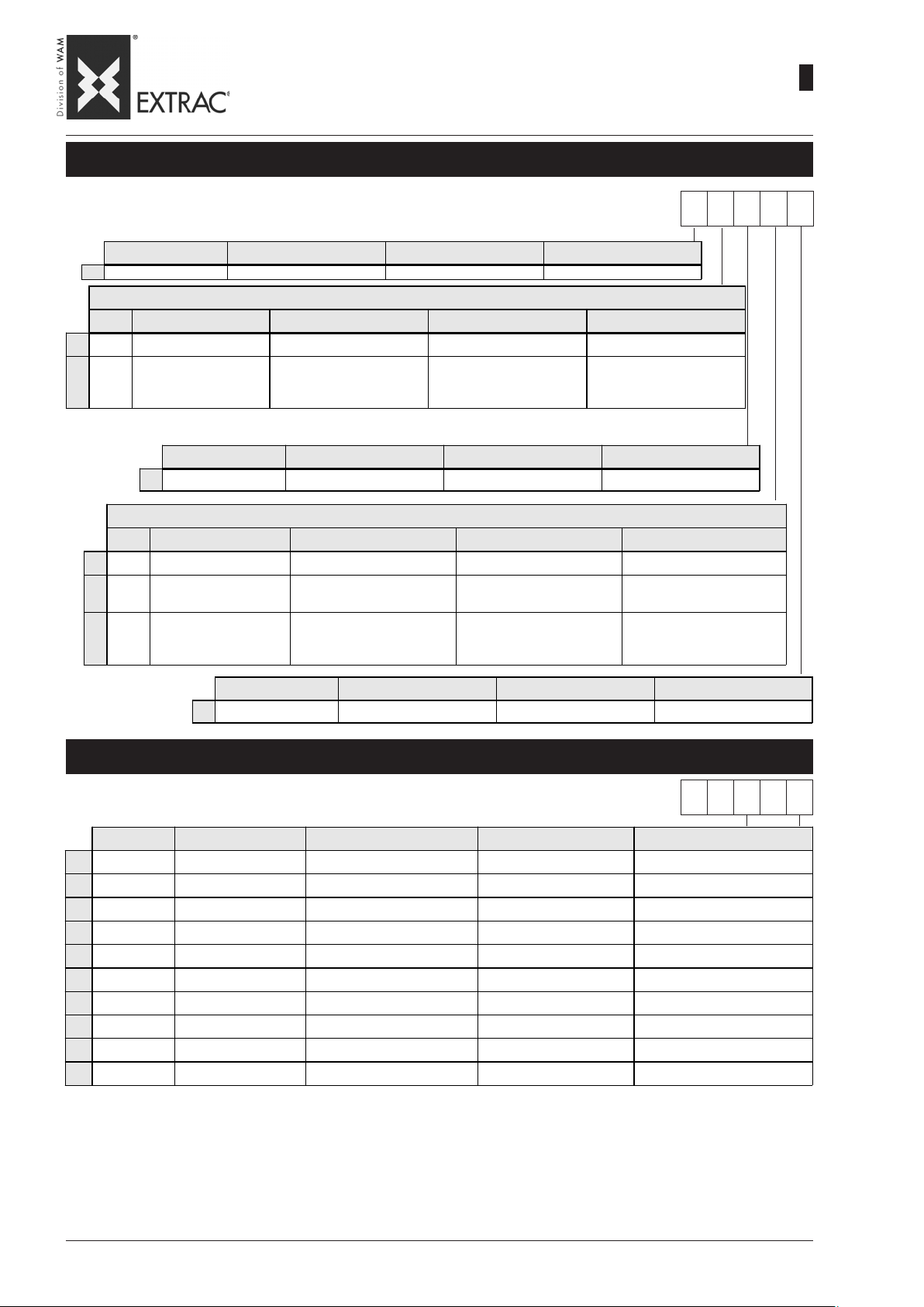
Vibrator Voltages/Frequencies - Spannung/Frequenzen Unwuchtmotor
Tensions / Fréquences du vibrateur - Tensioni / Frequenze vibratore
+ Without vibrator- Ohne Unwuchtmotor - Sans vibrateur - Senza vibratore
1 230/400V 50Hz (STD)
5 260/440V 60Hz
6 220/380V 60Hz
F 330/575V 60Hz
H 290/500V 50Hz
P 230/460V 60Hz
Page 14

SBB
-
FINISHING OF CARBON STEEL
-
FINISH AUS STAHL
-
FINITION ACIER AU CARBONE
-
FINITURA ACCIAIO AL CARBONIO
WA.14 T.
09.07
1
10
The term "finish" includes the
sequence and the operations
necessary for machining and
finishing a material.
The finish provided for the internal and external surfaces is
classified as:
4 (ACCURATE)
“4” FINISH (ACCURATE) - FINISH “4”(HOCHWERTIG) - FINITION “4” (SOIGNEE) - FINITURA “4”(ACCURATA)
MATERIALS WERKSTOFFE MATERIAUX MATERIALI
Plates Bleche Tôles Lamiere
OPERATION FEATURES
Plasma/Laser cut
Welding
Trimming
Clea ning weld s
Sand blasting
Painting
FERTIGUNG EIGENSCHAFTEN
Plasma-/Laserschnitt
Schweißen
Entgraten
Reinigung der
Schweißarbeit
Sandstrahlen
Anstreichen
FINITION CARACTÉRISTIQUES
Coupe au plasma/laser
Soudure
Ebavurage
Nettoyage soudures
Sablage
Peinture
LAVORAZIONE CARATTERISTICHE
Taglio al plasma/laser
Saldatura
Sbavatura
Pulizia salda t u re
Sabbiatura
Verniciatura
Mit Finish wird die Abfolge der
Arbeitsgänge beschrieben, welche erforderlich sind, um das
Produkt zu bearbeiten und fertigzustellen.
Das Finish für außen und innen
liegende Oberflächen ebtspricht
der Kategorie:
4 (HOCHWERTIG)
in normal mode, with attention to linearity and precision
Continuous, on all edges, MAG type, with attentio n to lineari ty
Removal of rags and sharp edges by grinding and sanding
Mechanical cleaning of welding slag by grinding
Internal and external sand blasting to prepare the surfaces for painting;, there must be no ruffles or
projections; extreme care to create continuity
See treatments and shades of internal and external surfaces pa ge T.11
normaler Ausführ ung, auf G er ad l inigk eit und Genauigke it achten
Auf allen Seiten kontinuierlich, Typ MAG-Verfahren, auf Geradlinigkeit achten
B es eitigung von Gra t en und s chnei dend en Ka nten mittels Sc hl eifen und S chmirg eln
Mechanische Reinigung der Schweißreste mittels Schleifen
Innen und auße n sa ndgestra hl t, um die O berf l äche n f ür d en Ans t rich vor zube reiten. Wede r Krä uselungen
noch Auskragungen dürfen festgestellt werden. Größte Aufmerksamkeit, um Kontinuierlichkei t zu erreic hen
S iehe Beha ndlun ge n und Fa rbton Anstri ch der Innen- und Außenfl ächen Sei te T.11
E n exé cut ion no rmale, en s oignant l a linéa ri té et la pr éc isio n
E n co ntinu, s u r tou s les bords , type : MA G en soignant l a linéa r it é
Elimination de bavures et arêtes coupantes, par meulage et ponçage.
Nettoyage mécanique des scories de soudure par meulage
Sablage extérieur et intérieur de préparation des surface pour peinture ; aucune saillie ni d'effets rugueux
ne doivent être constatés ; soin extrême dans la formation de la continuité
voir trai tements et tonalités des surfaces intérieures et extéri eures page T.11
di normale esecuzione, curandone linearità e precisione
In continuo , su t u t t i i l embi, t ipo : MAG curandon e linea ri t à
Eliminazione di ba ve e spigoli taglienti, tramite molatura e carteggi atura
Pulizia meccanica delle scorie di saldatura tramite molatura
Sabbia tura esterna e interna per predis porre le superfici per la verniciatura; non si devono riscontrare
increspature o sporgenze; estrema cura nel creare continuità
vedi trattamenti e tonalità superfi ci i nterne ed esterne pag. T.11
Par le terme "finition" on entend
la séquence et les opérations
nécessaires pour travailler et finir un matériau.
La finition prévue pour les surfaces internes et externes est
classée:
4 (SOIGNEE)
Con il termine “finitura” si intende la sequenza e le operazioni
necessarie per lavorare e finire
un materiale.
La finitura prevista per le superfici interne ed esterne è classificata:
4 (ACCURATA)
Page 15
SBB
-
FINISHING OF CARBON STEEL
-
FINISH AUS STAHL
-
FINITION EN ACIER AU CARBONE
-
FINITURA ACCIAIO AL CARBONIO
WA.14 T.
09.07
1
11
TRAITEMENTS DES SURFACES INTERIEURES ET EXTERIEURES - TRATTAMENTI SUPERFICI INTERNE ED ESTERNE
4
0
1
* With internal finish “9” only the “N” RAL 9010 shade available - Mit Innenfinish “9” ausschließlich Farbton “N” RAL 9010 lieferbar.
Avec finition interne « 9 » seule la teinte « N » RAL 9010 est disponible. - Con finitura interna “9” è disponibile esclusivamente la tonalità “N” RAL 9010
SURFACE TREATMENT INSIDE AND OUTSIDE - OBERFLÄCHENBEHANDLUNG INNEN UND AUSSEN
STANDARD
Finishing Finish Finition Finitura
ACCURATE HOCHWERTIG SOIGNEE ACCURATA
INTERNAL - INNEN - INTERIEUR - INTERNO
Ra Treatment Behandlung Traitement Trattamento
none keine aucune nessuna
SA 2,5 +
40 µm
1 primer coat (standard)
Pain t co lour Farbton Anstrich Tonalité Tonalità
See Table Siehe Tabelle Cf. Table Vedi Tabella
Ra Treatment Behandlung Traitement T rattamento
0
1
3
none keine aucune nessuna
40µmSA 2,5 +
1 primer coat
80µmSA 2,5 + 1 primer
+ 1 paint coat
SA 2,5 +
1 x Grund (serienmäßig)
EXTERNAL - AUSSEN - EXTERIEUR - ESTERNO
SA 2,5 +
1 x G rund
SA 2,5 + 1 x Grund
+ 1 x De c k
SA 2,5 +
1 couche antirouille
(de sé rie)
SA 2,5 +
1 co u che antir ouill e
SA 2,5 + 1 antirouille
+ 1 peinture
SA 2,5 +
1 mano antiruggine
(di serie )
SA 2,5 +
1 mano antiruggine
SA 2,5 + 1 mano
antiruggine
+ 1 m ano f ini re
4 1 0 3 I
Pain t co lou r Farbton Anstrich Tonalité Tonalità
See Table Si e he Tab elle C f. Table Ve di Ta bella
PAINT COLOUR INSIDE AND OUTSIDE - ANSTRICHFARBTON INNEN UND AUSSEN
TONALITES INTERIEURES ET EXTERIEURES - TONALITÁ INTERNE ED ESTERNE
STANDARD
RAL Pain t c olou r Farbton Anstrich Tonalité Tonalità
B
RAL 1013 pearl white Perlweiß blanc perle bianco perla
C
RAL 1015 light ivory Hellelfenbein ivoire clair avorio chiaro
D
RAL 5 010 gentian blue Enzia n blau bl eu ge nti ane bl u genzia na
E
RAL 5015 sky blue Himmelblau bleu ciel blu ci elo
G
RAL 7035 light grey Li chtgrau g ris lumière gri gi o luce
H
RAL 7032 pebble grey Kieselgrau gris gravier grigio ghiaia
I
RAL 7001 silver grey * Silbergrau * gris argent * grigio a rgento *
N
RAL 9010 pure white Reinweiß blanc pur bianco puro
Z
0
* = standard - serienmäßig - de série - di serie
N.B.: Finishing vibrator motors RAL 2004 - Finish: Vibrationsmotoren RAL 2004
- to be specified Zu spezi fizieren à préciser su specifica
- / RAL 8023 none / primer “beaver” K einer / Grundanstrich “Biber” aucune / anti rouille castor nessuna / antiruggine castoro
Finition motovibrateurws: RAL 2004 - Finitura motovibratori: RAL 2004.
4 1 0 3 I
THICKNESS IN MICRONMETRES (tolerance for 15 μm for each coat)
Ra =
SCHICHTDICKE IN MIKRONMETERN (Toleranz 15 µm für jede Schicht)
EPAISSEUR EN MICRON (tolérance 15 µm pour chaque couche)
SPESSORE IN MICRON (tolleranza 15 µm per ogni mano)
Page 16

SBB
-
FINISHING AISI 304L
-
FINISH 1.4306
-
FINITION AISI 304L
-
FINITURA AISI 304L
WA.14 T.
09.07
1
12
The term "finish" includes the
sequence and the operations
necessary for machining and
finishing a material.
The finish provided for the internal and external surfaces of the
pullers is classified as:
A (ACCURATE)
"A" FINISH (ACCURATE) - FINISH "A" (HOCHWERTIG) - FINITION "A" (SOIGNEE) - FINITURA “A” (ACCURATA)
MATERIALS WERKSTOFFE MATERIAUX MATERIALI
Plates Bleche Tôles Lamiere
Operation FEATURES
Plasma/Laser cut
Satin finishing Carried out on the inner surface of the cone after turning, using grinder SA80
Weldi ng Co ntinuous, on all edge s, type: TIG with fac ing for BA (04 0 -1 0 0 ), MIG with flux cored wi re BA (125 -300)
Trimming Removal of rags and sharp ed ges b y grinding and sanding
Cleaning welds Carried out with micro shot blasting or satin finishing SA240, depending on the selected finish
Micro shoot blasting
Satin finishing SA240, in successive passes, passing from SA80 to SA240
FERTIGUNG EIGENSCHAFTEN
Plasma-/Laserschnitt
Satinieren Auf der Innenfläche des Trichters nach dem Drehen mittels einer Schleifscheibe SA80 ausgeführt
Schweißen
Entgraten Beseitigung von Graten und schneide nden Kanten mittels Schleifen und Schmirgeln
Reinigung der
Schweißarbeit
Mikrokugelstrahlen
Satinieren SA240, in aufeinanderfolgenden Durchgängen von SA80 bis SA 240
FINITION CARACTÉRISTIQUES
Coupe a u plasma/laser
Satinage Réalisé sur la surface interne du cône après le tournage, par utilisation d'une meule SA80
Soudure
Ebavurage Elimination de bavures et arêtes coupantes, par meulage et ponçage.
Nettoyage Soudures Réalisé par micro-grenaillage ou satinage SA 240 se lon la finiti on choisie.
Micro-grenaillage
Satinage SA240, en passes successives allant de SA80 à SA240
LAVORAZIONE CARATTERISTICHE
Ta glio al plasma / laser Di normale secuzione, curandone linearità e preci sione
Satinatura Eseguita s ulla supe r fici e interna de l cono dopo la to rni tura, me d iante l'uso d i mola SA8 0
Saldatura In continuo, su tutti i lembi, tipo: TIG con riporto per BA (040-100), MIG con filo animato BA (125-300)
Sbavatura Eliminazione di bave e spigoli taglienti, tramite molatura e carteggiatura
Pulizia Sa ldature Eseguita con la mi cropa llinatura o satinatura S A 240 a s ec onda della finitura scelta
Micropallinatura
Satinatura SA240, in passate successive passando da SA80 a SA240
Unter dem Begriff “Finish” versteht man die Reihenfolge und
die Vorgänge, die erforderlich
sind, um ein Material zu bearbeiten und fertig zu stellen.
Das vorgesehene Finish für die
internen und externen Oberflächen der Austragsvorrichtung
wird klassifiziert mit:
A (HOCHWERTIG)
in normal mode, with attention to linearity and precision
Internal and external micro shot blasting, depending the finish selected, there must be no ruffles or
projections; extreme care to create continuity
normaler Aus führung, auf Geradlinigk eit und G ena uigkeit achten
Kontinuierlich im MIG-Verfahren mit Schweißdraht auf allen Seiten für BA (040-100), mit MIG-Verfahren mit
Schweißdra ht BA (125 -300)
Je nach dem gewählten Finish mittels Mikrokugelstrahlen oder Satinierung SA240 ausgeführt
Je nach de m g ewählt en Finish innen und a u ßen mikrokugelge stra hl t, W ede r Kr äuse lun gen no ch
Auskragungen dürfen festgestellt werden. Größte Aufmerksamkeit, um Kontinuierlichkeit zu erreichen
En exécution normale, en soignant la linéarité et la précision
En continu, sur tous les bords, type: TIG avec métal d'apport pour BA (040-100), MIG avec fil fourré BA
(125-300)
Micro-grenaillage extérieur et intérieur selon la finition choisie, aucune saillies ni d'effets rugueux ne doivent
être constatés ; soin extrême dans la formatio n de la continuité.
Micropallinatura esterna e i nterna a seconda d ella finitura scelta, non si devono riscontrare increspature o
sporgenze; estrema cura nel creare continuità
Par le terme “finition” on entend
la séquence et les opérations
nécessaires pour travailler et finir un matériau.
La finition prévue pour les surfaces internes et externes des
extracteurs est classée:
A (SOIGNEE)
Con il termine “finitura” si intende la sequenza e le operazioni
necessarie per lavorare e finire
un materiale.
La finitura prevista per le superfici interne ed esterne è classificata:
A (ACCURATA)
Page 17
-
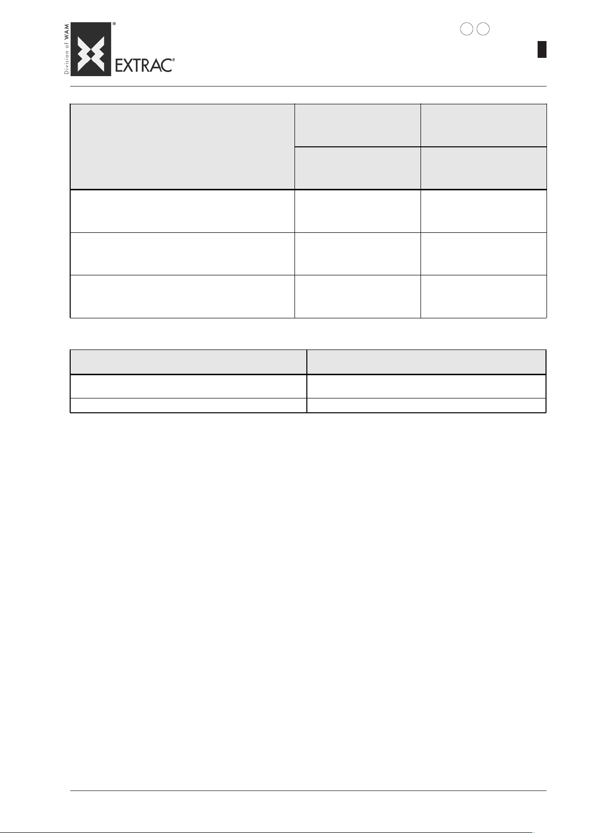
FINISHING: STAINLESS STEEL
-
SBB
HOPPER SURFACE TREATMENT INSIDE AND OUTSIDE - TRICHTER-OBERFLÄCHENBEHANDLUNG INNEN UND AUSSEN
TRAITEMENTS SUPERFICIES INTÉRIEURES ET EXTÉRIEURES TRÉMIE - TRATTAMENTO SUPERFICI INTERNE ED ESTERNE TRAMOGGIA
FINISH: EDELSTAHL
-
FINITION: ACIER INOX
-
FINITURA: ACCIAIO INOX
09.07
WA.14 T.
1
13
Finishing Finish Finition Finitura
A
INTERNAL - INNEN - INTÉRIEUR - INTERNO
D
E
0
EXTERNAL - AUSSEN - EXTÉRIEUR - ESTERNO
Treatment Behandlung Traitement Trattamento
D
ACCURATE HOCHWERTIG SOIGNEE ACCURATA
Treatment Behandlung Traitement Trattamento
Silking Satinieren Satinage Satinatura
SA 60-80 SA 60-80 SA 60-80 SA 60-80
Silking Satinieren Satinage Satinatura
SA 120-180 SA 120-180 SA 120-180 SA 120-180
Paint colour Farbton Anstrich Tonalité Tonalità
None Keiner Aucune Nessuna
Silking Satinieren Satinage Satinatura
SA 60-80 SA 60-80 SA 60-80 SA 60-80
ST ANDARD
AD D0
0
Paint colour Farbton Anstrich Tonalité Tonalità
0
VERSION WITH CONTACT P ARTS IN SS - VERSION PRODUKTERÜHRENDE TEILE AUS EDELST AHL
None Keiner Aucune Nessuna
VERSION PARTIES EN CONT ACT EN INOX - VERSIONE PARTI IN CONT A TTO AISI
FRAME OUTSIDE SURFACE TREA TMENT: POWDER (RAL 7001)
BEHANDLUNG DER AUSSENFLÄCHEN DES GESTELLS: STAUBBESCHICHTET (RAL 7001)
TRAITEMENT SURFACES EXTÉRIEURES CHÂSSIS POUDRE (RAL 7001)
TRATTAMENTO SUPERFICI ESTERNE TELAIO: POLVERE (RAL 7001)
VERSION ENTIREL Y IN SS - VERSION KOMPLETT AUS EDELST AHL
VERSION ENTIEREMENT EN INOX - VERSIONE COMPLET AMENTE IN AISI
FRAME OUTSIDE SURFACE TREA TMENT: Glass bead blasted
BEHANDLUNG DER AUSSENFLÄCHEN DES GESTELLS: Glasperlengestrahlt
TRAITEMENT SURFACES EXTÉRIEURES CHÂSSIS: Microbillage
TRATTAMENTO SUPERFICI ESTERNE TELAIO: Micropallinato
MOTOR-VIBRA TOR: RAL 2004
VIBRATIONSMOTOR: RAL 2004
MOTOVIBRA TEUR: RAL 2004
MOTOVIBRATORE: RAL 2004
Page 18
SBB
-
MATERIALS AND FINISHING: NUTS AND BOL TS
-
WERKSTOFFE UND FINISH: SCHRAUBTEILE
-
MATERIAUX ET FINITION: BOULONNEIRE
-
MATERIALI E FINITURE: BULLONERIA
1142
09.07
1
WA.14 T.
HOPPER CONSTRUCTION MATERIAL
WERKSTOFF DES TRICHTER
MATÉRIAU DE CONSTRUCTION TRÉMIE
MATER IA LE COS T RU ZIONE TRAM OGGIA
Fe St
Parts in contact with the product made of 304L St. st.
Produktberührende Teile aus Edelstahl 1.4306
Parties en contact avec le produit en inox AISI 304L
Parti a contatto prodotto in AISI 304L
All made from 304L St. st.
Alles aus Edelstahl 1.4306
Complètement en inox AISI 304L
Com pl e tame nte in AISI 304L
FRAME MATERIAL - MATERIAL DES RAHMENS
MATÉRIAU DU CHÂSSIS - MATERIALE TELAIO
Fe St
AISI 304L AISI 304
INTERNAL NUTS AND BOLTS
SCHRAUBTEILE INNEN
BOULONNERIE INTÉRIEURE
BULLONERIA INTERNA
Grille
Gitter
Grille
Griglia
Zinc plated
Kaltverzinkt
Galvanisée à froid
Zincata a freddo
304 St. st.
1.4306
AISI 304 (A2)
AISI 304
304 St. st.
1.4306
AISI 304 (A2)
AISI 304
EXTERNAL NUTS AND BOLTS - AUSSEN-SCHRAUBTEILE
BOULONNERIE EXTÉRIEURE- BULLONERIA ESTERNA
Zinc plated - Kaltverzinkt
Galvanisée à froid - Zincata a freddo
EXTERNAL NUTS AND BOLTS
SCHRAUBTEILE FÜR AUSSEN
BOULONNEIRE EXTERIEUR
BULLONERIA ESTERNA
Flange stop-sleeve
Flan sch Dichtmanschette
Bride â rre te -joint
Flangia fermaguarnizione
Zinc plated
Kaltverzinkt
Galvanisée à froid
Zincata a freddo
Zinc plated
Kaltverzinkt
Galvanisée à froid
Zincata a freddo
304 St. st.
1.4306
AISI 304 (A2)
AISI 304
Page 19
SBB
-
DIMENSIONS - MODEL T
-
EINBAUMASSE - MODELL T
-
DIMENSIONS - MODELE T
-
DIMENSIONI - MODELLO T
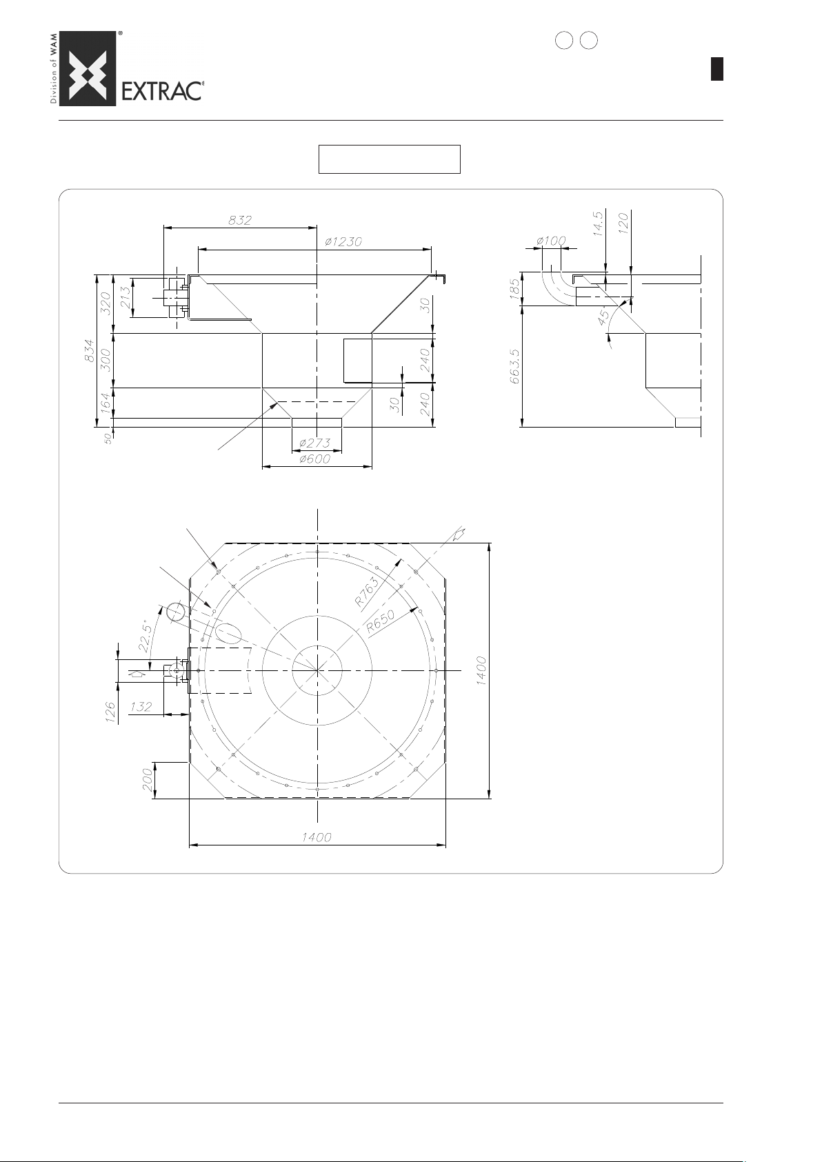
SBB._.125.T
3154
09.07
1
WA.14 T.
Safety finger mesh - Schutzgitter
Grille de protection - Griglia antinfortuni
Slots - Langlöcher - Rainures - Asole
bores - Bohr. - Trous - fori
N° 24 x ø 16
N°4 25 x16
Page 20
SBB
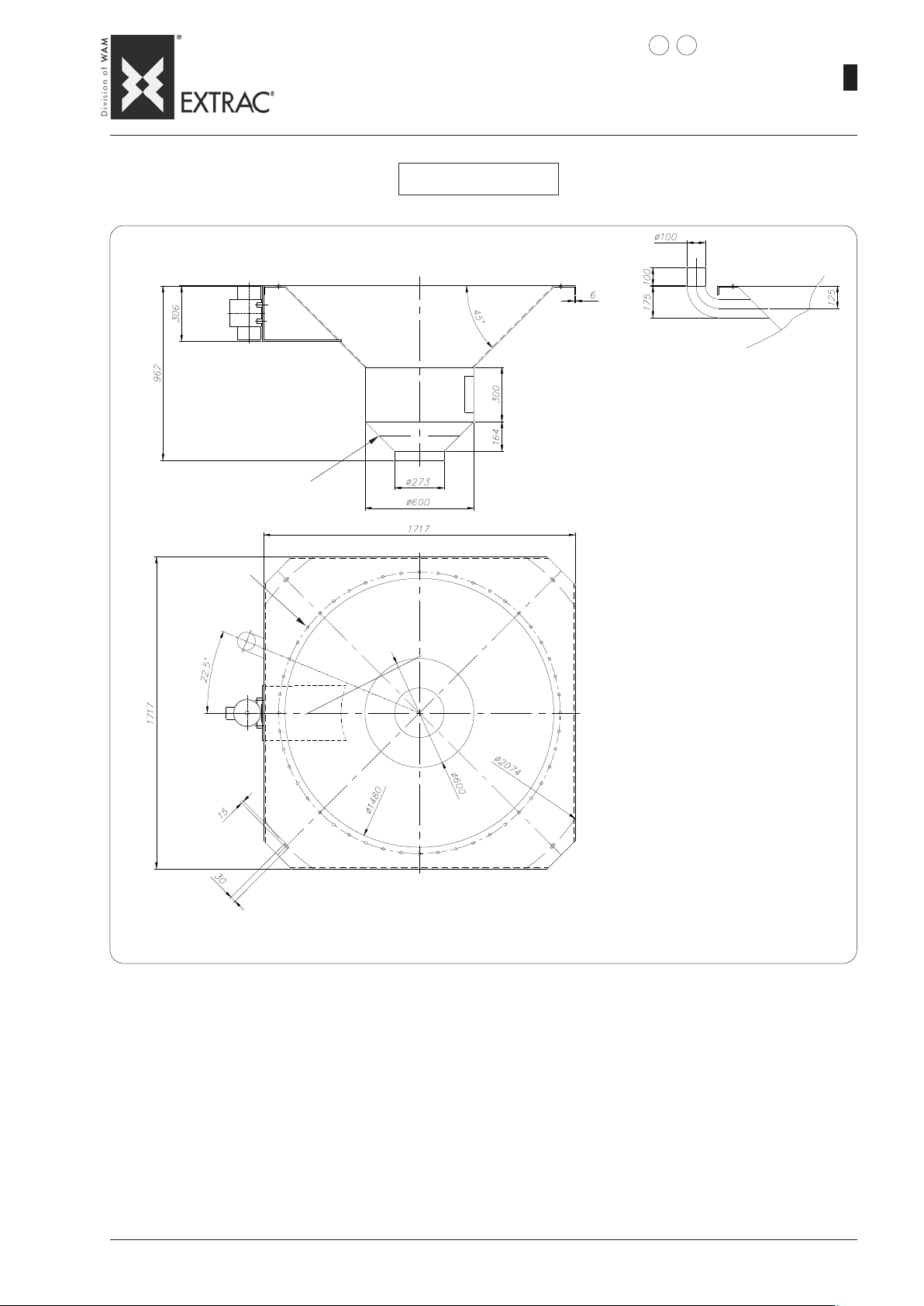
Safety finger mesh - Schutzgitter
Grille de protection - Griglia antinfortuni
-
DIMENSIONS - MODEL T
-
EINBAUMASSE - MODELL T
-
DIMENSIONS - MODELE T
-
DIMENSIONI - MODELLO T
SBB._.150.T
3 4
WA.14 T.
09.07
1
16
N° 48 x ø 16
Feed side
Aufgabeseite
Côté chargement
Lato carico
Page 21
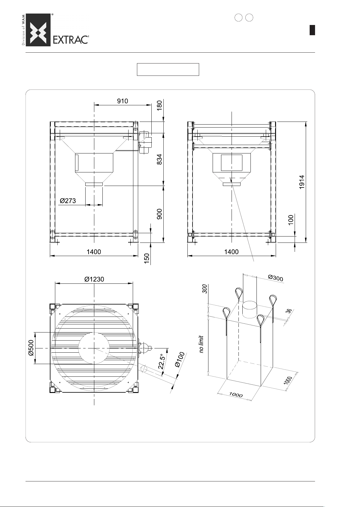
SBB
-
DIMENSIONS - MODEL C
-
EINBAUMASSE - MODELL C
-
DIMENSIONS - MODELE C
-
DIMENSIONI - MODELLO C
SBB._.125.C
3 4
WA.14 T.
09.07
1
17
Feed side
Aufgabeseite
Côté chargement
Lato carico
Safety finger mesh - Schutzgitter
Grille de protection - Griglia antinfortuni
Page 22
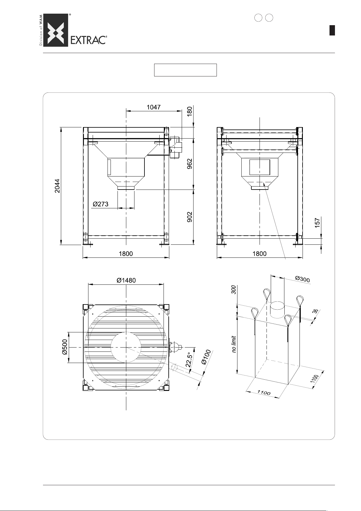
SBB
-
DIMENSIONS - MODEL C
-
EINBAUMASSE - MODELL C
-
DIMENSIONS - MODELE C
-
DIMENSIONI - MODELLO C
SBB._.150.C
3 4
WA.14 T.
09.07
1
18
Feed side
Aufgabeseite
Côté chargement
Lato carico
Safety finger mesh - Schutzgitter
Grille de protection - Griglia antinfortuni
Page 23
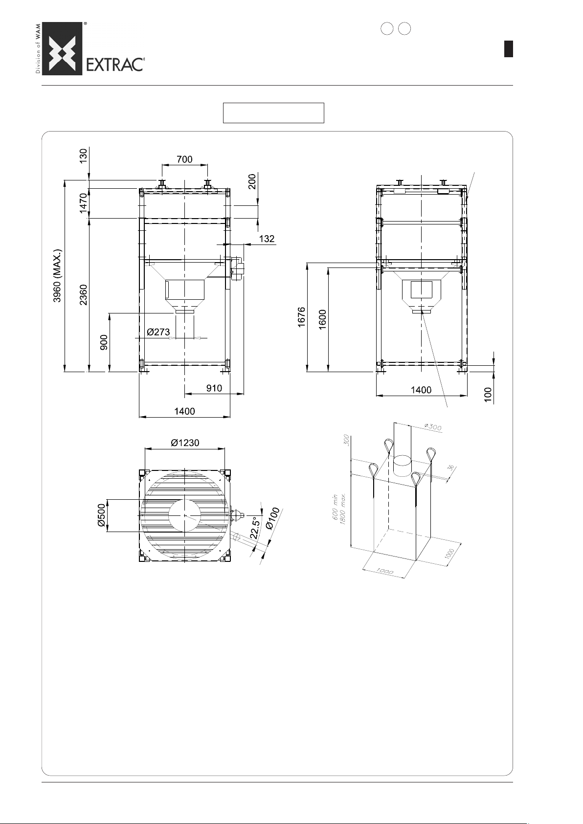
SBB
-
DIMENSIONS - MODEL S
-
EINBAUMASSE - MODELL S
-
DIMENSIONS - MODELE S
-
DIMENSIONI - MODELLO S
SBB._.125.S
3 4
WA.14 T.
7 bores Ø17 pitch 200
7 Bohrungen Ø17 T eil. 200
7 trous Ø17 pas 200
N° 7 fori Ø17 passo 200
09.07
1
19
Feed side
Aufgabeseite
Côté chargement
Lato carico
NOTE: The heights given are theoretical.
They do not take into account deformation of filled FIBCs.
HINWEIS:Die genannten Höhen sind theoretische Werte.
Sie berücksichtigen nicht die Verformung des gefüllten Big-Bags.
REMARQUES : Les hauteurs indiquées sont théoriques.
Elles ne tiennent pas compte des déformations des Big-Bag pleins.
NOTE: Le altezze indicate sono teoriche.
Non tengono conto delle deformazioni dei Big-Bag pieni.
Safety finger mesh - Schutzgitter
Grille de protection - Griglia antinfortuni
Page 24
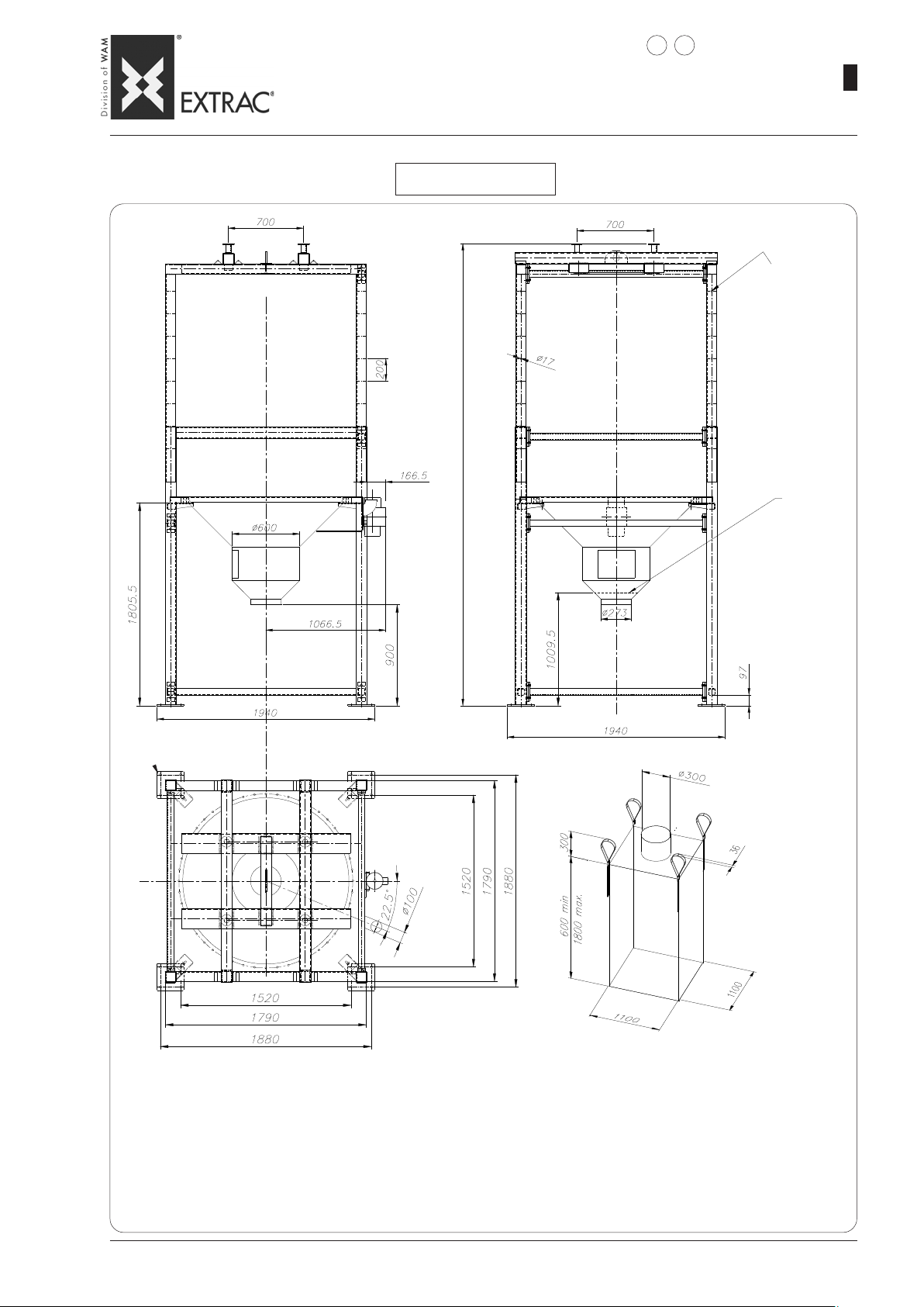
SBB
-
DIMENSIONS - MODEL S
-
EINBAUMASSE - MODELL S
-
DIMENSIONS - MODELE S
-
DIMENSIONI - MODELLO S
SBB._.150.S
3 4
09.07
WA.14 T.
7 bores Ø17 pitch 200
7 Bohrungen Ø17 Teilung 200
7 trous Ø17 pas 200
N° 7 fori Ø17 passo 200
Safety finger mesh
Schutzgitter
Grille de protection
Griglia antinfortuni
1
20
4 bores Ø 22 - 4 Bohrungen Ø22
4 trous Ø22 - N° 4 fori Ø22
(Maximum lift - Max. Hubhöhe - Levée maximum - Alzata massima)
NOTE: The heights given are theoretical.
They do not take into account deformation of filled FIBCs.
HINWEIS:Die genannten Höhen sind theoretische Werte.
REMARQUES : Les hauteurs indiquées sont théoriques.
NOTE: Le altezze indicate sono teoriche.
Sie berücksichtigen nicht die Verformung des gefüllten Big-Bags.
Elles ne tiennent pas compte des déformations des Big-Bag pleins.
Non tengono conto delle deformazioni dei Big-Bag pieni.
Page 25
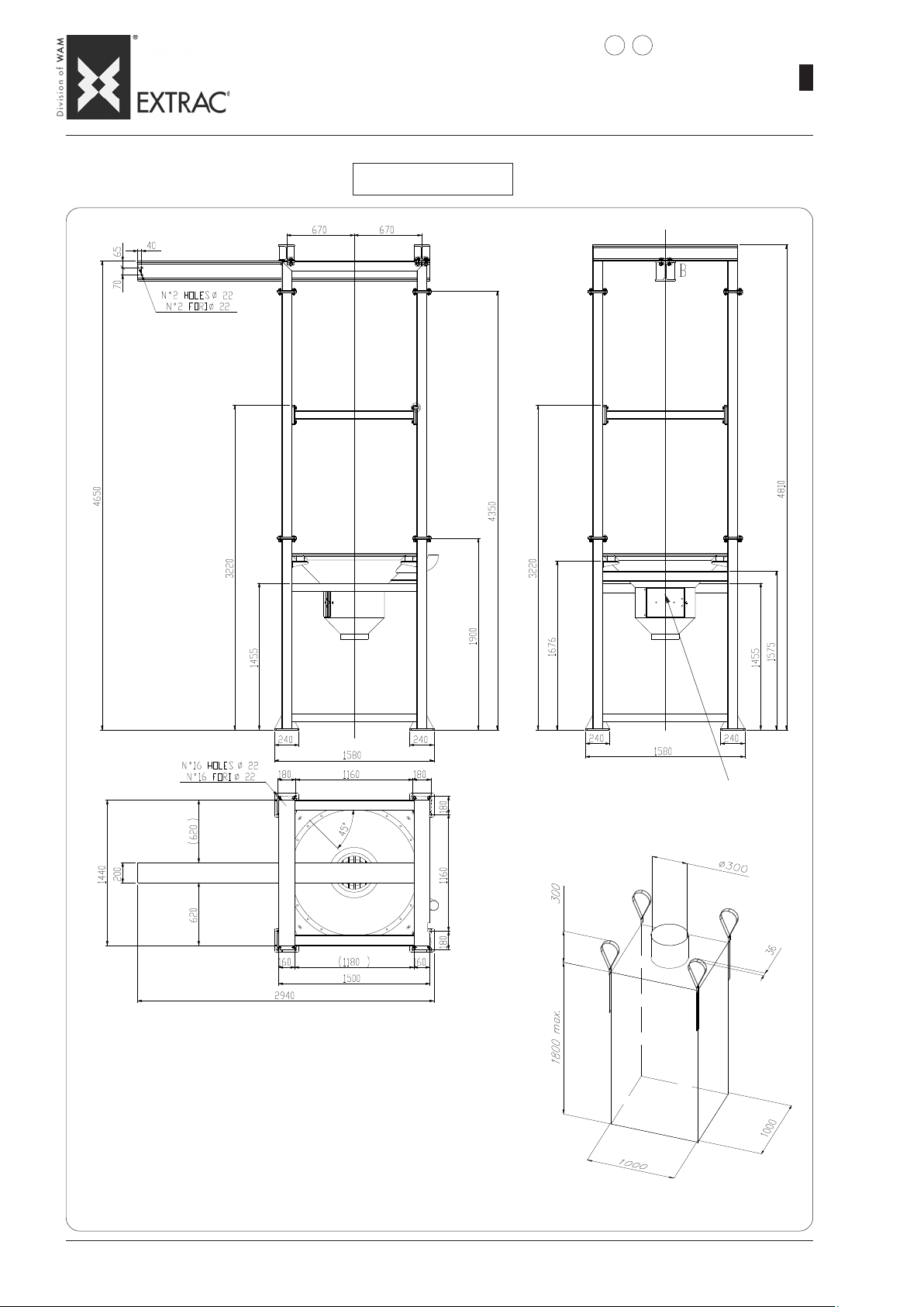
SBB
-
DIMENSIONS - MODEL M
-
EINBAUMASSE - MODELL M
-
DIMENSIONS - MODELE M
-
DIMENSIONI - MODELLO M
SBB._.125.M
3 4
WA.14 T.
09.07
1
21
Feed side
Aufgabeseite
Côté chargement
Lato carico
NOTE: The heights given are theoretical.
They do not take into account deformation of filled FIBCs.
The hoist is not included in the WAM® supply
HINWEIS:Die genannten Höhen sind theoretische Werte.
REMARQUES : Les hauteurs indiquées sont théoriques.
NOTE: Le altezze indicate sono teoriche.
Sie berücksichtigen nicht die Verformung des gefüllten Big-Bags.
Der Flaschenzug gehört nicht zum Lieferumfang von WAM
Elles ne tiennent pas compte des déformations des Big-Bag pleins.
Le palan est exclu de la fourniture WAM
Non tengono conto delle deformazioni dei Big-Bag pieni.
Il paranco è escluso dalla fornitura WAM
®
Safety finger mesh - Schutzgitter
Grille de protection - Griglia antinfortuni
®
®
Page 26
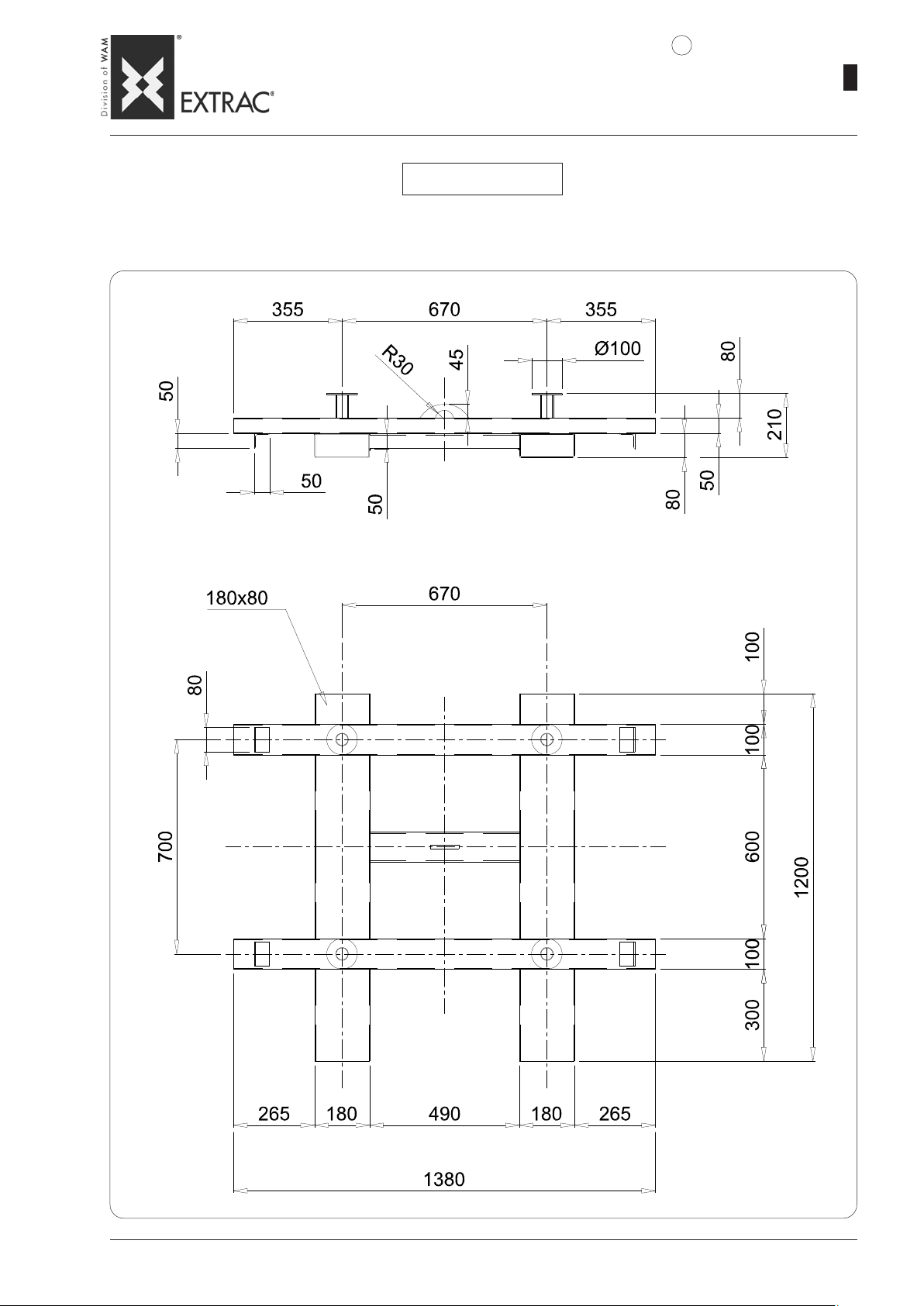
-
SBB
DIMENSIONS - FIBC LIFTING FRAME
-
EINBAUMASSE - BIG-BAG - HEBEGESTELL
-
DIMENSIONS - CHÂSSIS DE SOULÈVEMENT BIG-BAG
-
DIMENSIONI - TELAIO DI SOLLEV AMENTO BIG-BAG
4
SBB._.125.S
MAX. CAPACITY 1600 daN ( CLASS A5 ) - MAX. TRAGLAST 1600 daN (KLASSE A5)
CAPACITÉ MAXI 1600 daN (CLASSE A5) - PORTATA MAX. 1600 daN ( CLASSE A5 )
WA.14 T.
09.07
1
22
Page 27

-
SBB
DIMENSIONS - FIBC LIFTING FRAME
-
EINBAUMASSE - BIG-BAG - HEBEGESTELL
-
DIMENSIONS - CHÂSSIS DE SOULÈVEMENT BIG-BAG
-
DIMENSIONI - TELAIO DI SOLLEVAMENTO BIG-BAG
4
SBB._.150.S
MAX. CAPACITY 2500 daN ( CLASS A5 ) - MAX. TRAGLAST 2500 daN (KLASSE A5)
CAPACITÉ MAXI 2500 daN (CLASSE A5) - PORTATA MAX. 2500 daN ( CLASSE A5 )
WA.14 T.
09.07
1
23
Page 28
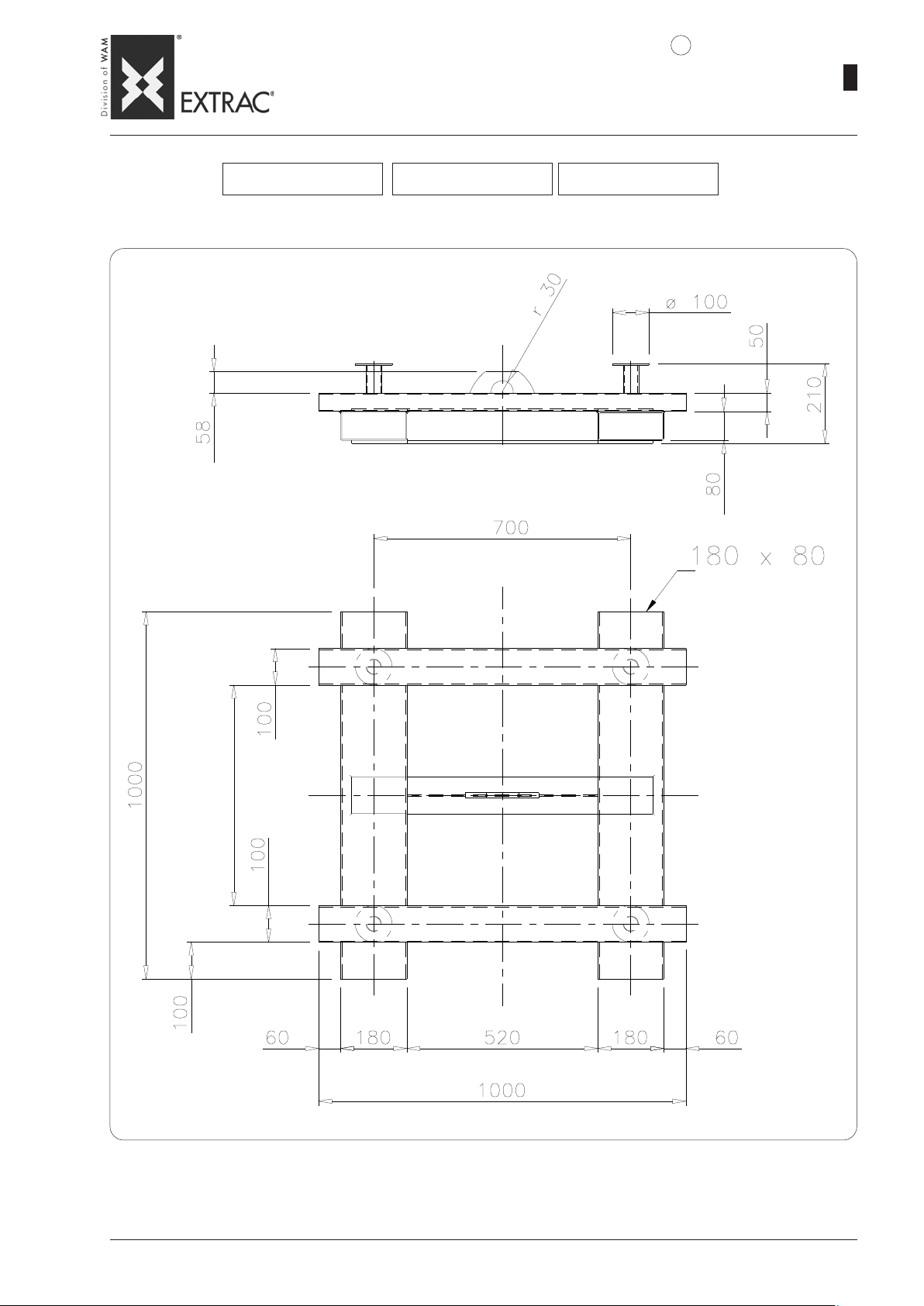
-
SBB
DIMENSIONS - FIBC LIFTING FRAME
-
EINBAUMASSE - BIG-BAG - HEBEGESTELL
-
DIMENSIONS - CHÂSSIS DE SOULÈVEMENT BIG-BAG
-
DIMENSIONI - TELAIO DI SOLLEVAMENT O BIG-BAG
4
SBB._.125.C SBB._.125.M SBB._.150.C
MAX. CAPACITY 2000 daN ( CLASS A5 ) - MAX. TRAGLAST 2000 daN (KLASSE A5)
CAPACITÉ MAXI 2000 daN (CLASSE A5) - PORTATA MAX. 2000 daN ( CLASSE A5 )
WA.14 T.
09.07
1
24
Page 29
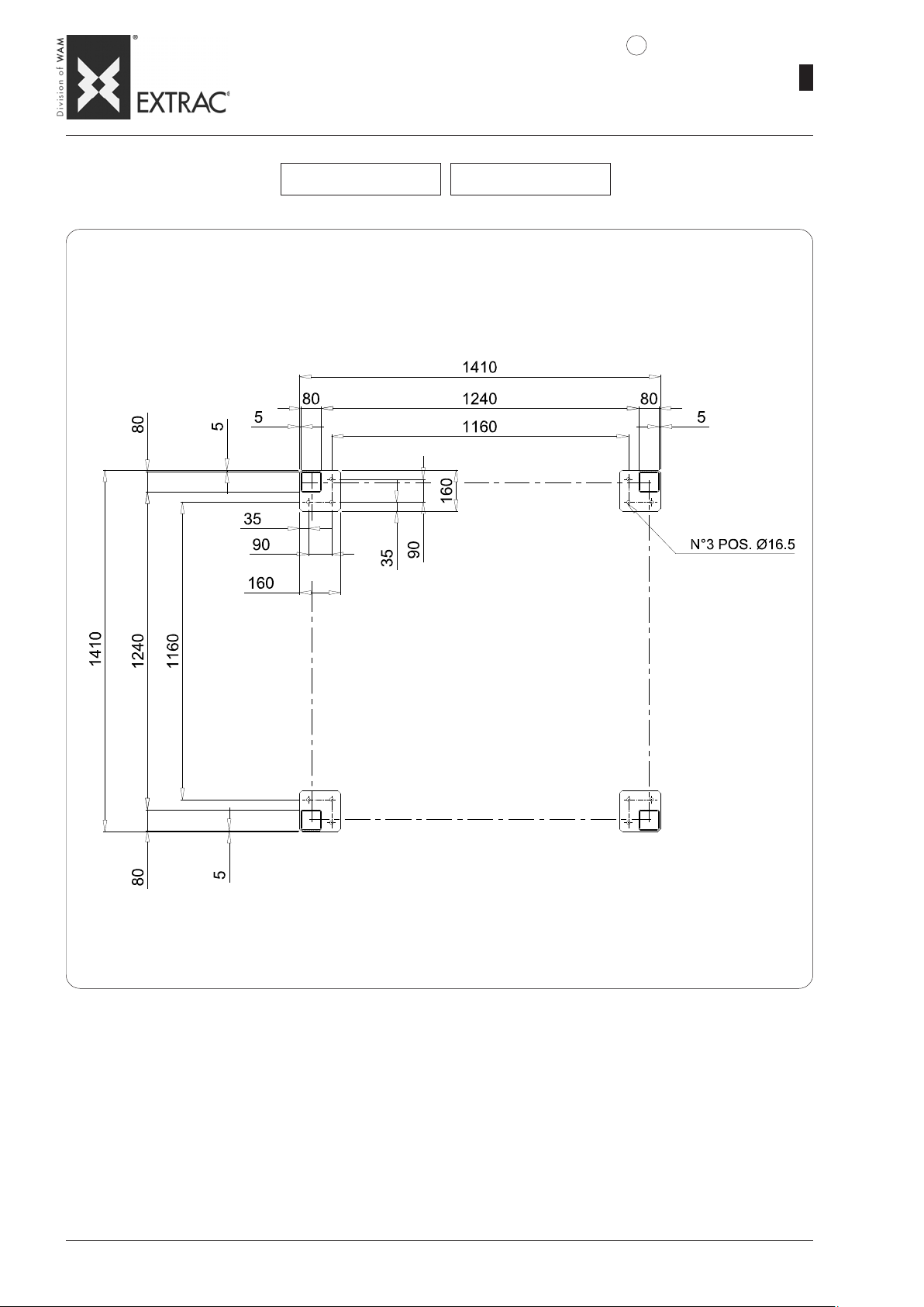
SBB
-
DIMENSIONS - FOUNDATION PLAN
-
EINBAUMASSE - FUNDAMENTPLAN
-
DIMENSIONS - PLAN D’ANCRAGE
-
DIMENSIONI - PIANTA DI FISSAGGIO
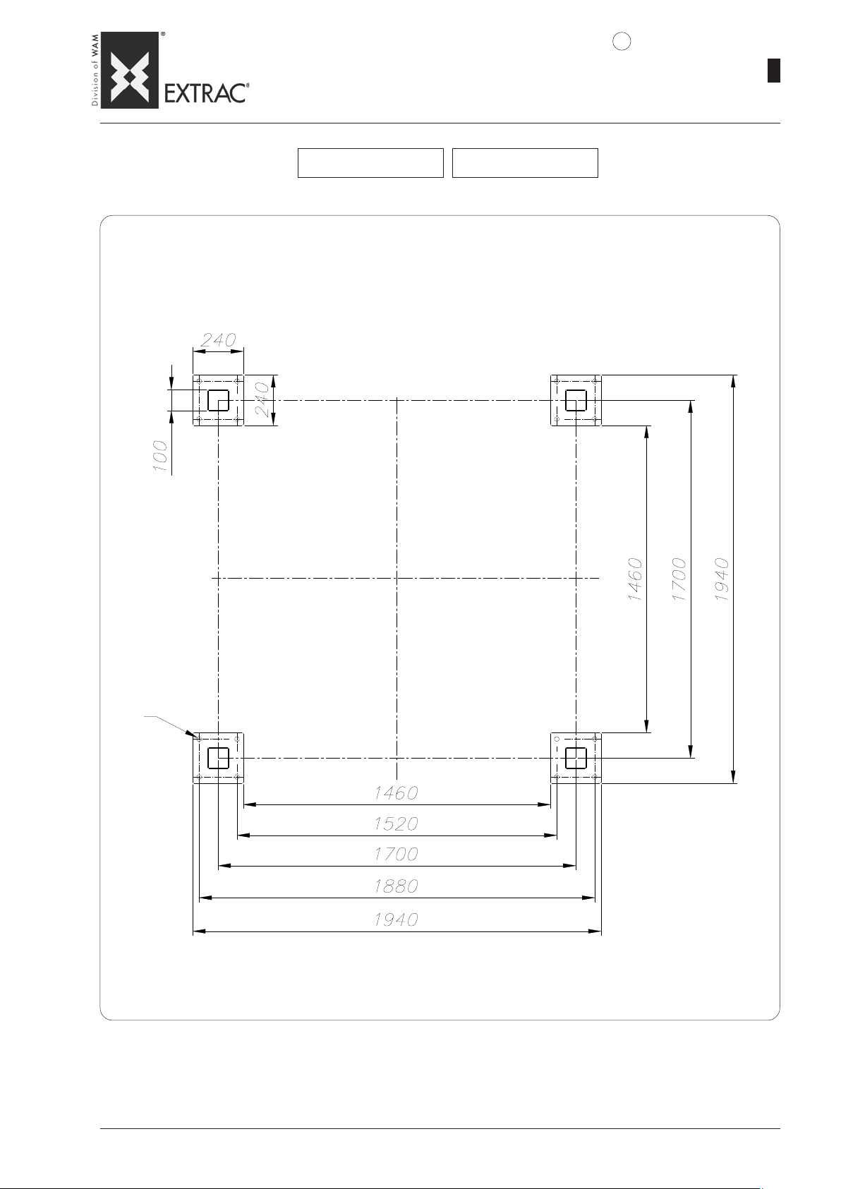
SBB._.125.C SBB._.125.S
4
09.07
1
WA.14 T.
25
TOT AL DYNAMIC VER TICAL LOAD
VERTIKALE DYNAMISCHE GESAMTLAST
CHARGE VERTICALE DYNAMIQUE TOT ALE
CARICO VERTICALE DINAMICO COMPLESSIVO
N max. = 2600 daN
TOT AL TILTING T ORQUE
GESAMTKIPPMOMENT
COUPLE DE BASCULEMENT TOT AL
COPPIA DI RIBAL T AMENTO COMPLESSIV A
Mf max. = 358 daN · m
MAX. CAPACITY 1600 daN (CLASS A5)
MAX. TRAGLAST 1600 daN (KLASSE A5)
CAPACITÉ MAXI 1600 daN (CLASSE A5)
PORTATA MAX. 1600 daN (CLASSE A5)
Page 30
SBB
-
DIMENSIONS - FOUNDATION PLAN
-
EINBAUMASSE - FUNDAMENTPLAN
-
DIMENSIONS - PLAN D’ANCRAGE
-
DIMENSIONI - PIANTA DI FISSAGGIO
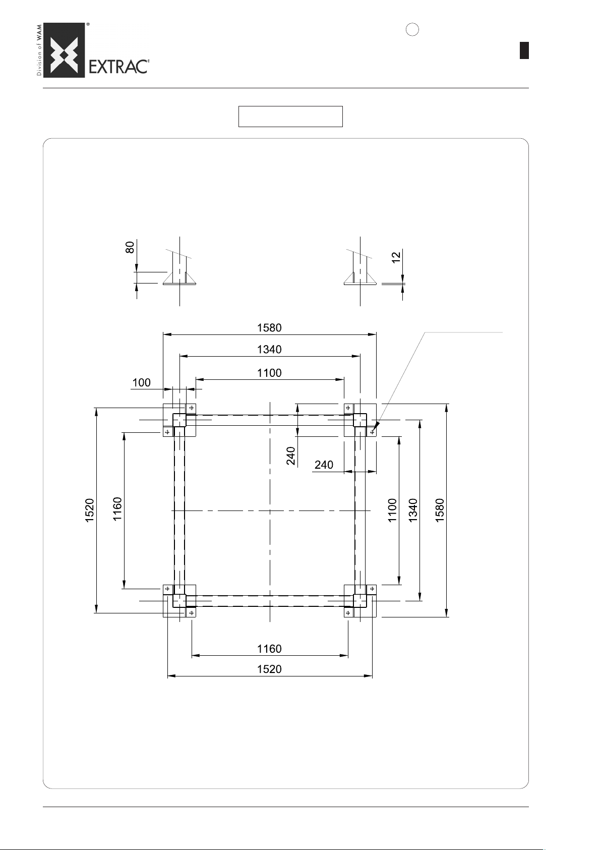
SBB._.150.C SBB._.150.S
4
09.07
1
WA.14 T.
26
TOT AL DYNAMIC VER TICAL LOAD
VERTIKALE DYNAMISCHE GESAMTLAST
CHARGE VERTICALE DYNAMIQUE TOT ALE
CARICO VERTICALE DINAMICO COMPLESSIVO
N max. = 4000 daN
TOT AL TILTING T ORQUE
GESAMTKIPPMOMENT
COUPLE DE BASCULEMENT TOT AL
COPPIA DI RIBALTAMENTO COMPLESSIVA
Mf max. = 1125 daN · m
4 bores Ø 22
4 Bohrungen Ø22
4 trous Ø22
N° 4 fori Ø22
MAX. CAPACITY x daN ( CLASS A5 )
MAX. TRAGLAST x daN (KLASSE A5)
CAPACITÉ MAXI x daN (CLASSE A5)
PORTATA MAX. x daN ( CLASSE A5 )
Page 31
SBB
-
DIMENSIONS - FOUNDATION PLAN
-
EINBAUMASSE - FUNDAMENTPLAN
-
DIMENSIONS - PLAN D’ANCRAGE
-
DIMENSIONI - PIANTA DI FISSAGGIO
SBB._.125.M
4
09.07
1
WA.14 T.
27
TOT AL DYNAMIC VER TICAL LOAD
VERTIKALE DYNAMISCHE GESAMTLAST
CHARGE VERTICALE DYNAMIQUE TOT ALE
CARICO VERTICALE DINAMICO COMPLESSIVO
N max. = 3400 daN
TOT AL TILTING T ORQUE
GESAMTKIPPMOMENT
COUPLE DE BASCULEMENT TOT AL
COPPIA DI RIBALTAMENTO COMPLESSIVA
Mf max. = 6150 daN · m
N°2 POS. x Ø22
MAX. PULL FOR EACH ANCHORING BOL T: N1 = 1250 daN
MAX. ZUG PRO ANKERSCHRAUBE: N1 = 1250 daN
TRACTION MAXI DE CHAQUE TIGE D'ANCRAGE: N1 = 1250 daN
TIRO MAX PER CADAUNA ZANCA DI ANCORAGGIO: N1 = 1250 daN
MAX. CAPACITY 2000 daN ( CLASS A5 )
MAX. TRAGLAST 2000 daN (KLASSE A5)
CAPACITÉ MAXI 2000 daN (CLASSE A5)
PORTATA MAX. 2000 daN ( CLASSE A5 )
Page 32
SBB
-
OPTIONS: CUTTING SYSTEM
-
OPTIONEN: AUFSCHNEIDEVORRICHTUNG
-
OPTIONS: SYSTÈME DE COUPE
-
OPZIONI: SISTEMA DI TAGLIO
5
09.07
1
WA.14 T.
28
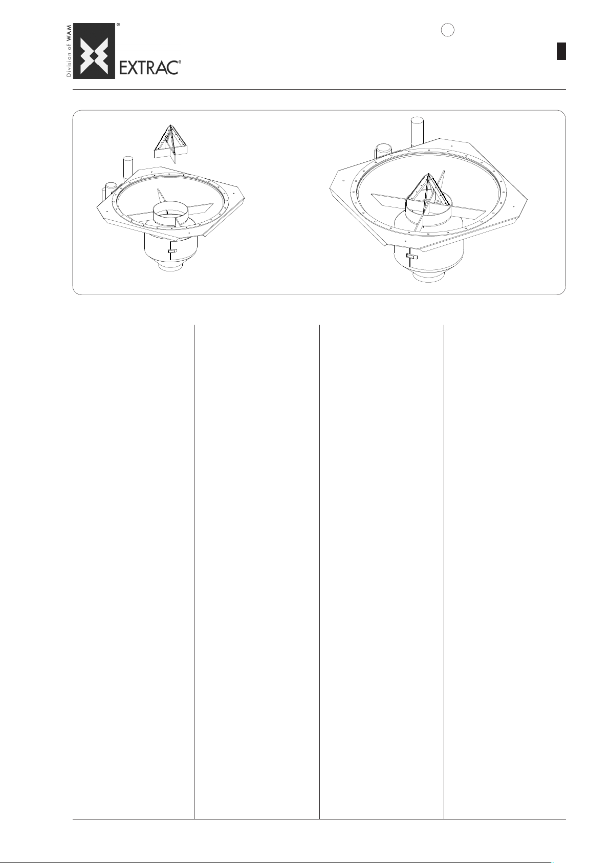
Its function is to cut valveless
FIBCs which cannot be recycled.
N.B.: The blades can be removed
so as to enable use also with
FIBCs having valves.
Accessory applicable on all SBB
models.
The knife blade is always made
of Fe 430 mild steel, while the
supporting frame is made of the
same material as the FIBC.
Zum Aufschneiden von Einweg-BigBags ohne Auslaß-ventil.
N.B.: Die Messer können herausgenommen werden, da-mit auch
Big-Bags ohne Ventil verarbeitet
werden können.
Zubehör, das bei jedem Modell
der SBB angewendet werden
kann.
Die Messerklinge besteht jeweils
aus St 430, während das
Traggestell aus dem gleichen
Werkstoff wie die Big-Bag
Entleerstation gefertigt ist.
Sa fonction est de couper les
gros sacs sans valve irrécupérables.
N.B.: les couteaux sont démontables de manière à permettre de
travailler aussi les BIG BAG avec
valve.
Accessoire applicable à chaque
modèle de SBB.
La lame des couteaux est toujours réalisée en Fe 430, tandis
que le châssis de soutien est
réalisé dans le même matériau
que le vide BIG-BAG.
Ha la funzione di tagliare BIG BAG
senza valvola non recuperabili.
N.B.: i coltelli sono smontabili in
modo da consentire di svuotare
anche i BIG BAG con valvola.
Accessorio apllicabile ad ogni
modello di SBB.
La lama dei coltelli è sempre realizzata in Fe 430, mentre il telaio
di sostegno viene realizzato con
lo stesso materiale dello svuota
BIG-BAG.
Page 33
SBB
-
OPTIONS: PNEUMATIC ACTIVATORS
-
OPTIONEN: PNEUMATISCHE AUSTRAGHILFEN
-
OPTIONS: ACTIVA TEURS PNEUMA TIQUES
-
OPZIONI: ATTIVA T ORI PNEUMATICI
6
09.07
1
WA.14 T.
29
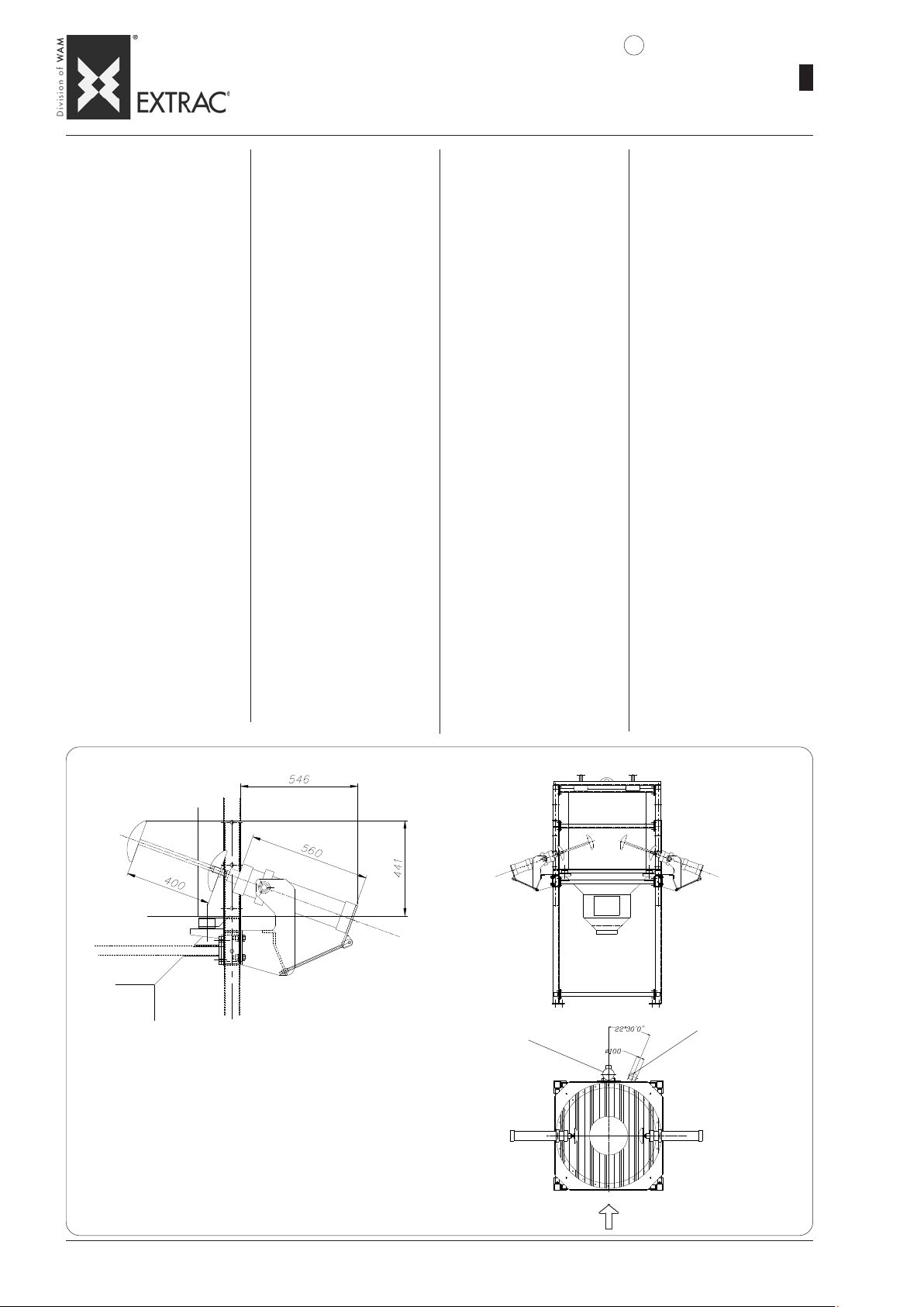
- Materials featuring poor flowability
do not flow out of the FIBC easily.
It is therefore necessary to use
pneumatic activators. These devices act directly at the bottom of the
FIBC, causing lifting and lowering
of the opposite corners to stimulate the flow of material compacted
at the bottom.
The gradual movement of the activators makes the FIBC assume a
"V" shape, to eliminate the deadlock points.
In field 6 of the order code, select
from the following options:
+ + + = SBB without actuators
KCS = Actuators Kit without control
panel
KSQ = Actuators Kit with electro-pneumatic control panel
KSP = provision for actuators kit (In
the latter case, the activators are not
supplied)
N.B.: The pneumatic activators can
be installed on SSB ONLY if provi-
sion has been made on the latter during the order phase.
The weight of the pneumatic actuators is approximately 80 kg.
ADVANT AGES:
1) System functional and easy to
install.
2) Possibility of adjustment to opti-
mize operation.
EXECUTION:
1) Carbon steel
2) 304L SS depending on the ma-
terial used for constructing the
SBB frame.
- Materialien, die nur schwach rieselfähig sind und nur schwer aus dem
Big-Bag ausgetragen werden können,
verlangen den Einsatz pneumatischer Austraghilfen. Diese wirken
direkt auf den unteren Teil des BigBags und bewegen die gegenüberliegenden Sackkanten auf- und
abwärts, damit das im unteren Bereich verdichtete Material abläuft.
Das ständige Ausfahren der Austraghilfe dient dazu, daß der Big-Bag
eine V-förmige Gestalt annimmt,
wodurch T oträume beseitigt werden.
Im Feld 6 des Bestellcodes kann man
unter den folgenden Optionen wählen:
+ + + = SBB ohne Austraghilfen
KCS = Bausatz Austraghilfen ohne
Schaltkasten
KSQ = Bausatz Austraghilfen mit
elektrisch-pneumatischem Schaltkasten
KSP = Vorrüstung für Bausatz Austraghilfen (im letzteren Fall gehören
die Austraghilfen nicht zum Lieferumfang)
N.B.: Die pneumatischen Austraghilfen können NUR dann auf dem SBB
installiert werden, wenn dies bei der Bestellung der Vorrichtung bereits vorgesehen wurde.
Die pneumatischen Austraghilfen haben ein Gewicht von circa 80 kg.
VORTEILE:
1) Funktionelles und einfach zu instal-
lierendes System.
2) Einstellmöglichkeit zur Betriebsop-
timierung.
AUSFÜHRUNG:
1) Normstahl
2) Edelstahl 1.4306 je nach dem
Werkstoff, der für das Gestell
des SBB benutzt worden ist.
- Les matières peu fluides ne sortent
pas facilement des sacs. Il est donc
nécessaire d'appliquer des activateurs pneumatiques. Ils agissent directement sur le fond des "big bag"
en déterminant un rehaussement ou
un abaissement des angles opposés de manière à stimuler la sortie
du produit compacte sur le fond.
Le mouvement progressif des activateurs fait prendre une forme en
"V" au big bag de manière à éliminer
les points morts.
Dans le champ 6 du code de commande on peut choisir entre les options suivantes :
+ + + = SBB sans actionneurs
KCS = Kit actionneurs sans tableau
de commande
KSQ = Kit actionneurs avec tableau
électrique-pneumatique de commande
KSP = réservé pour kit actionneurs
(Dans ce dernier cas les actionneurs
ne sont pas fournis)
N.B.: Les activateurs pneumatiques
peuvent être installés sur le SBB
SEULEMENT si celui-ci a été prévu
pour recevoir ce dispositif lors de la
commande.
Les poids des actionneurs pneumatiques est d’environ 80 kg.
A VAN TAGES:
1) Système fonctionnel et facile à
installer.
2) Possibilité de réglage pour optimi-
ser le fonctionnement.
REALISATION
1) Acier au carbone
2) Acier inox 304L selon le matériau
de fabrication du châssis de
l’SBB.
- I materiali poco scorrevoli non
escono facilmente dai big bag
pertanto si rende necessario applicare degli attivatori pneumatici.
Questi agiscono direttamente sul
fondo dei big bag determinando
un innalzamento e un abbassamento degli spigoli opposti in
modo da stimolare la fuoriuscita
del materiale compattato sul fondo.
La progressiva escursione degli
attivatori fa si che il big bag assume la forma a "V" in modo da eliminare i punti morti.
Nel campo 6 del codice di ordinazione è possibile scegliere tra le
seguenti opzioni:
+ + + = SBB senza attivatori
KCS = Kit attivatori senza quadro di
comando
KSQ = Kit attivatori con quadro elettro-pneumatico di comando
KSP = predisposizione per kit attivatori (In quest’ultimo caso gli attivatori non sono forniti)
N.B.: Gli attivatori pneumatici possono essere installati sull’ SBB
SOLO se questo è già stato predisposto in fase d’ordine.
Il peso degli attivatori pneumatici
è di circa 80kg.
VAN T AGGI:
1) Sistema funzionale e di facile in-
stallazione.
2) Possibilità di regolazione per ot-
timizzarne il funzionamento.
ESECUZIONE:
1) Acciaio al carbonio
2) Aisi 304L dipendentemente dal
materiale di esecuzione del telaio dell’SBB.
NOTES: For more information, see specific Catalogue KSC.
Accessory applicable on all SBB models.
NOTEN: Nähere Informationen siehe Katalog KSC.
Für alle SBB-Modelle verwendbares Zubehör.
REMARQUES: Pour plus d'informations voir spécifique Catalogue KSC.
Accessoire applicable à chaque modèle de SBB.
NOTE: Per ulteriori informazioni consultare Catalogo specifico KSC.
Accessorio applicabile ad ogni modello di SBB
FILTER BAG
FILTERSCHLAUCH
MANCHON FILTRANT
MANICA FILTRANTE
VIBRAT OR MOT OR
VIBRATIONSMOTOR
MOTOVIBRATEUR
MOTOVIBRATORE
FIBC LOAD SIDE
BIG-BAG AUFGABESEITE
CÔTÉ CHARGEMENT BIG-BAG
LATO CARICO BIG-BAG
Page 34
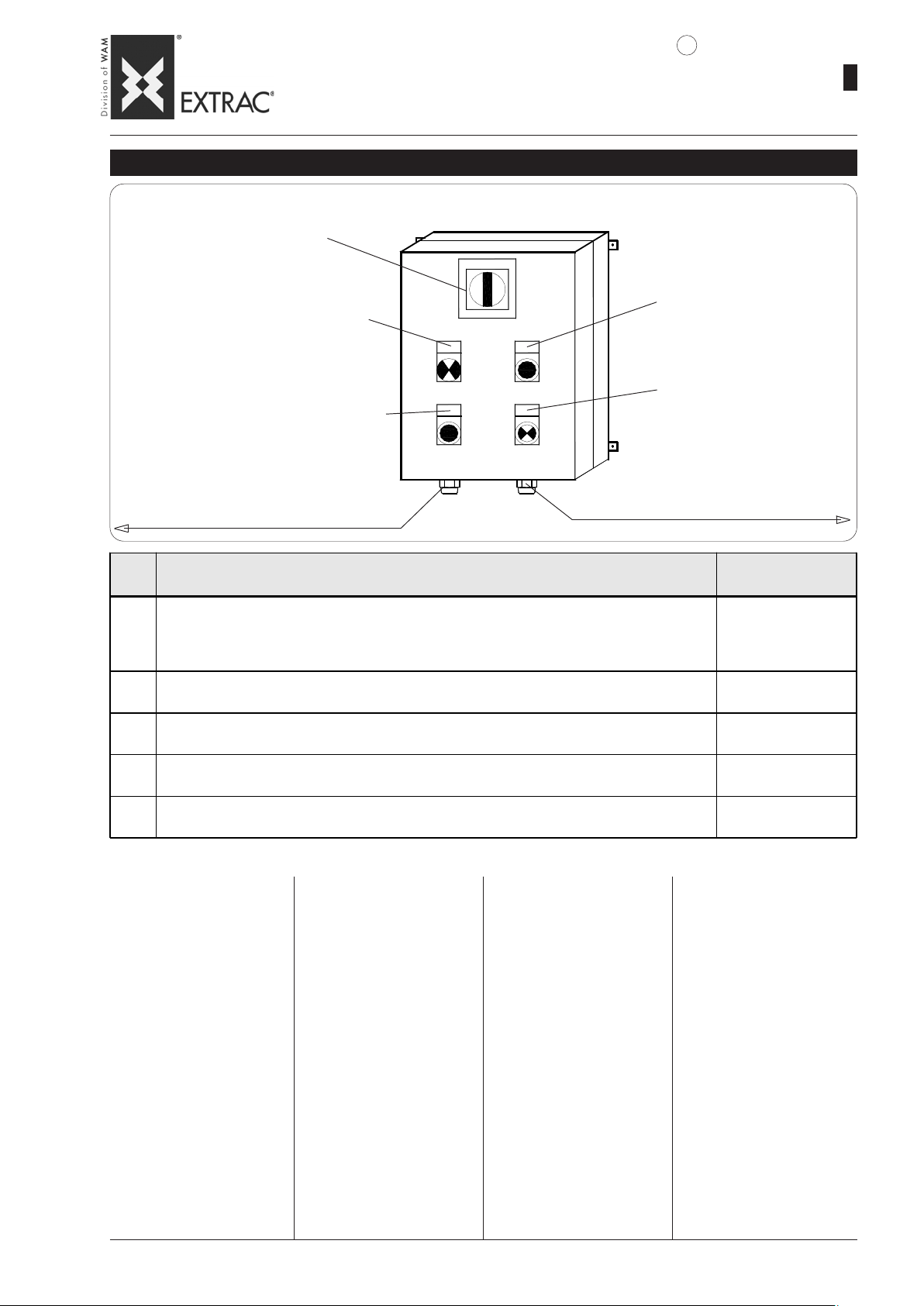
-
SBB
OPTIONS-PNEUMATIC ACTUA TORS
-
OPTIONEN – PNEUMA TISCHE AUSTRAGHILFEN
-
OPTIONS - ACTIONNEURS PNEUMA TIQUES
-
OPZIONI - ATTIVATORI PNEUMATICI
6
ELECTRIC CONTROL PANEL - ELEKTROSCHALTKASTEN - ARMOIRE ÉLECTRIQUE - QUADRO ELETTRICO
MAIN SWITCH
HAUPTSCHALTER
INTERRUPTEUR GÉNÉRAL
INTERRUTTORE GENERALE
CYCLE STAR T PUSHBUTTON
MAN./AUT . CYCLE SELECTOR
WAHLSCHALTER ZYKLUS HANDB../AUTOM.
SÉLEC. CHOIX CYCLE MAN. & AUTOM.
QS
TASTE FÜR ZYKLUS-START
BOUTON DÉBUT CYCLE
PULSANTE INIZIO CICLO
SELETT. SCELTA CICLO MAN. & AUTOM.
PG16
SB
EMSA1
CYCLE STOP PUSHBUTTON
TASTE FÜR ZYKLUS-STOP
BOUTON ARRÊT CYCLE
PULSANTE STOP CICLO
ELECTRIC POWER SUPPL Y INPUT
EINGANG FÜR STROMVERSORGUNG
ENTRÉE ALIMENTA TION ÉLECTRIQUE
INGRESSO ALIMENTAZIONE ELETTRICA
SINGLE/IN PAIRS CYCLE SELECT OR
WAHLSCHALTER ZYKLUS ABWECHS./SIMULTAN
SÉLECTEUR CHOIX CYCLE MAN. / AL T .
SELETT. SCELTA CICLO ALT. & SIMUL.
PNEUMATIC P ANEL POWER SUPPLY
VERSORGUNG PNEUMATIKSTEUERUNG
ALIMENTA TION ARMOIRE PNEUMATIQUE
ALIMENTAZIONE QUADRO PNEUMATICO
SA2
PG21
WA.14 T.
09.07
1
30
ITEM
POS.
MAIN SW ITCH - HAUPTSCHALTER
QS
INTERRUPTEUR GÉ NÉRAL - INTERRUTTORE GENERALE
CYCLE START PUSHBUTTON - TASTE FÜR ZYKLUS-START
SB
BOUTON DÉBUT CYCLE - PULS ANTE INIZIO CICLO
CYCLE STOP PUSHBUTTON - TASTE FÜR ZYKLUS-STOP
EM
BOUTON ARRÊT CYCLE - PULSANTE STOP CICLO
SINGLE/IN PAIRS CYCLE SELECTOR - WAHLSCHALTER ZYKLUS ABWECHSELND - SIMULTAN
SA1
SÉLECTEUR CHOIX C YCLE ALT. - SIMULT. - SELETTORE SCELTA CICLO ALTERNATIVO -SIMULTANEO
MAN./AUT. C YCLE SELECTOR - WAHLSCHALTER ZYKLUS MANUELL - AUTOMATISCH
SA2
SÉLECTEUR CHOIX C YCLE MAN. - AUT. - SELETTORE SCELTA CICLO MANU ALE - AUTOMATICO
DESCRIPTION - BENENNUNG - DÉSIGNATION - DENOMINAZI ONE
The control board comprises a
box with front door on which the
controls and operation indicators
are fitted.
Description of controls and
indicators:
SB/EM = PUSHBUTTONS:
controls with single operating mode
SA = SELECTORS:
double-function switches
QS = SWITCHES:
controls with two possible
positions.
Die elektrische Steuerung ist mit
einer Tür ausgestattet, auf der
sich die Bedienelemente und
Kontrollanzeigen befinden.
Beschreibung der Bedienelemente und Kontrollanzeigen:
SB/EM = DRUCKKNÖPFE:
Bedienelemente mit nur einer
Betriebsart.
SA = WAHLSCHAL TER:
Bedienelemente mit zwei Betriebsarten.
QS = SCHALTER:
Bedienelemente mit zwei
möglichen Positionen.
L`armoire électrique de commande est constituée d'un boîtier à porte frontale sur lequel
sont montés les commandes et
témoins de fonctionnement.
Description commandes et
indicateurs:
SB / EM = BOUTONS: comman-
des avec un seul mode de
fonctionnemnt.
SA= SÉLECTEURS: commuta-
teurs à deux fonctions.
QS=INTERRUPTEURS comman-
des à deux positions possibles.
COLOUR - FARBE
COULEUR - COLOR E
RED – YELLOW
ROT –GELB
ROUGE – JAUNE
ROSSO - GIALLO
BLACK - SCHWARZ
NOIR - NERO
RED - ROT
ROUGE - ROSSO
BLACK - SCHWARZ
NOIR - NERO
BLACK - SCHWARZ
NOIR - NERO
Il quadro elettrico di comando è
costituito da una cassetta con
portello frontale sul quale sono
montati dei comandi ed indicatori
di funzionamento.
Descrizione comandi ed indicatori:
SB / EM =PULSANTI:
sono comandi con un'unica
modalità di funzionamento
SA=SELETTORI:
sono commutatori a due funzioni.
QS=INTERRUTTORI:
sono comandi con due posizioni possibili.
Page 35
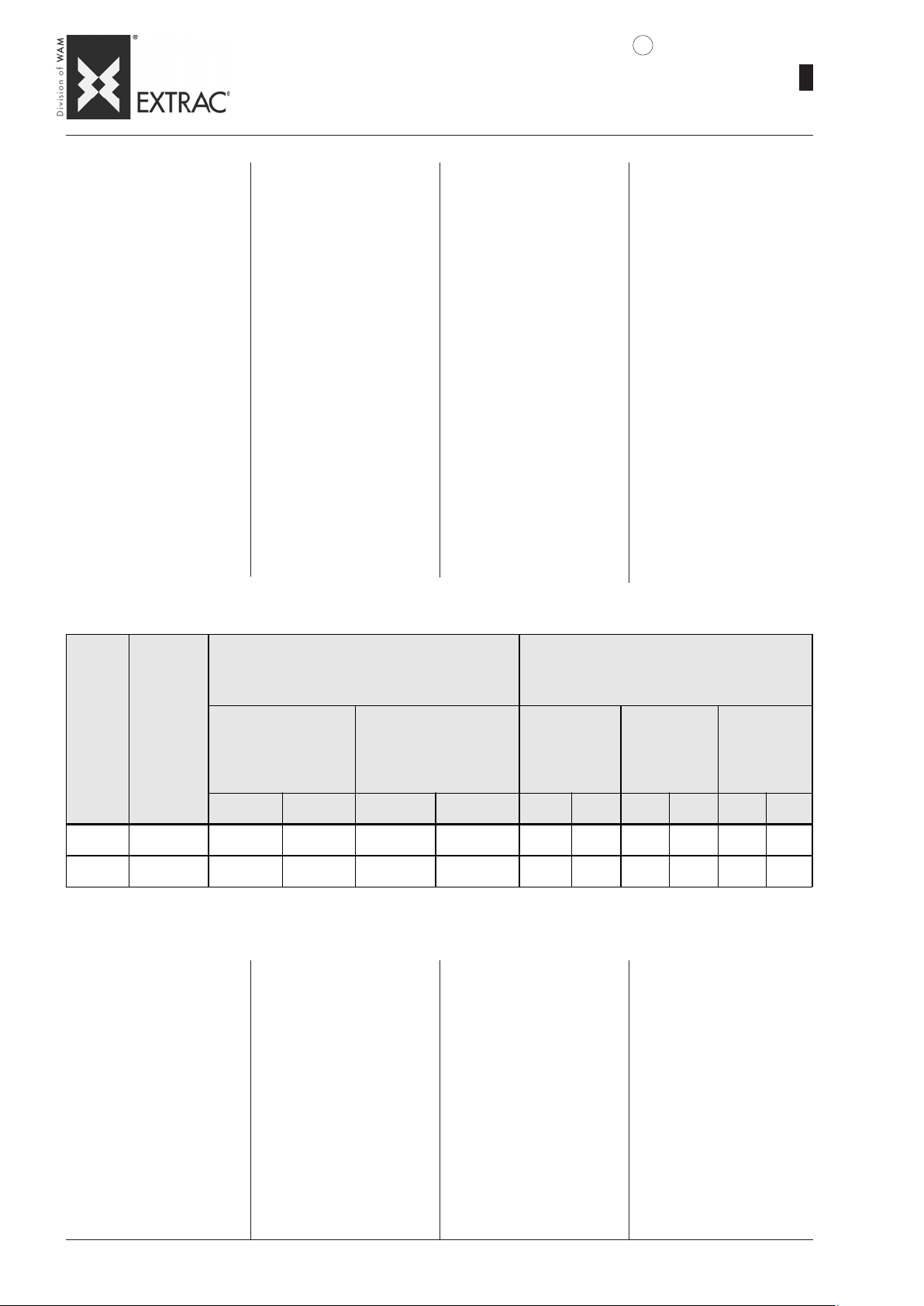
SBB
-
OPTIONS: VIBRAT OR
-
OPTIONEN: VIBRATION
-
OPTIONS: VIBRATEUR
-
OPZIONI: VIBRATORE
7
09.07
1
WA.14 T.
31
ELECTRIC VIBRAT OR MOTORS
Each SBB model is provided with
an electric vibrator motor to activate and facilitate descent of the
product; the vibrating mass on
each vibrator can be adjusted in
a simple manner (see use and
maintenance catalogue) to increase or decrease the centrifugal force.
For the SBB._.125 model it is
possible to mount a bigger vibrator, as shown in the Table below.
In field 7 of the order code it is
possible to select from the following options:
+ + = without vibrator
10 = vibrator 0.10 kW (std for
SBB 125)
18 = vibrator 0.18 kW (std for
SBB 150)
ELEKTRISCHE VIBRATIONSMOTOREN
Für jedes SBB-Modell gibt es
einen elektrischen Unwuchtmotor,
um den Ablauf des Produkts in
Gang zu bringen und zu vereinfachen. Auf jedem Unwuchtmotor
kann man die Unwuchtmassen auf
einfache Weise einstellen (siehe
betr. Betriebs- und Wartungsanleitung), um die Fliehkraft zu erhöhen
oder zu verringern.
Für das Modell SBB._.125 besteht die Möglichkeit, einen Unwuchtmotor größerer Bauart zu
montieren, wie folgende Tabelle
zeigt.
Im Feld 7 des Bestellcodes kann
man unter folgenden Optionen
wählen:
+ + = ohne Unwuchtmotor
10 = Unwuchtmotor 0,1 kW (Stan-
dard für SBB 125)
18 = Unwuchtmotor 0,18 kW
(Standard für SBB 150)
MOTOVIBRATEURS ÉLECTRIQUES
Chaque modèle SBB est équipé
d’un motovibrateur électrique qui
active et facilite la descente du
produit. Sur chaque vibrateur il
est possible de régler les masses vibrantes de manière très
simple (voir le catalogue d’utilisation et d’entretien) pour augmenter ou diminuer la force centrifuge.
Pour le modèle SBB._.125 il est
possible de monter un vibrateur
de taille supérieure, comme l’indique le tableau suivant.
Dans le champ 7 du code de commande on peut choisir entre les
options suivantes :
+ + = sans vibrateur
10 = vibrateur 0,1 kW (std pour
SBB 125)
18 = vibrateur 0,18 kW (std pour
SBB 150)
MOTOVIBRA TORI ELETTRICI
Ciascun modello di SBB è provvisto di un motovibratore elettrico per
attivare e agevolare la discesa del
prodotto; su ciascun vibratore è
possibile regolare le masse vibranti in modo molto semplice (vedere
catalogo uso e manutenzione) per
aumentarne o diminuirne la forza
centrifuga. Per il modello
SBB._.125 vi è la possibilità di
montare un vibratore di taglia superiore, come mostrato in tabella
seguente.
Nel campo 7 del codice di ordinazione è possibile scegliere tra le
seguenti opzioni:
+ + = senza vibratore
10 = vibratore 0,10 kW (std per
SBB 125)
18 = vibratore 0,18 kW (std per
SBB 150)
MERKMALE MECHANISCHER VIBRATOREN
CARACTERISTIQUES MECANIQUES VIBRATEUR
CARATTERISTICHE MECCANICHE VIBRATORE
SBB TYPE
50Hz 60Hz 50Hz 60Hz 50Hz 60Hz 230V 40 0V 267V 460V
125 MVE 100/3
125-150 MVE 200/3
TECHNICAL DA T A
- Standard power supply:
230/400 V 50 Hz
264/470 V 60 Hz
- Protection degree IP 65.
- Standard tropicalization.
- Continuous running.
- Operating temperature:
from -30° to +40°C
- Standard applicable:
IEC 34.1 - CEI 2/3 ; 73/72/CEE EN 292-89/CCE - EMC 89/336/
CE
- Vibrator motors with voltages
and frequencies different from
the standard production can be
supplied on request.
3000 3600 99 107 0.10 0.11 0.33 0.19 0.32 0.18
3000 3600 198 190 0.18 0.21 0.60 0.35 0.62 0.35
VIBRATOR MECHANICAL FEATURES
CENTRIFUGAL FORCE
FLIEHKRAFT
rpm/min
TECHNISCHE DATEN
- Standardstromanschluß:
230/400 V 50 Hz
264/470 V 60 Hz
- Schutzart IP 65.
- Serienmäßiger Tropenschutz.
- Funktion mit Dauerbetrieb.
- Betriebstemperatur:
von -30° bis +40°C
- Normen:
IEC 34.1 - CEI 2/3 ; 73/72/CEE EN 292-89/CCE - EMC 89/336/
CE
- Auf Anfrage werden Vibrationsmotoren realisiert, die von
der Standardproduktion abweichende Spannungen und
Frequenzen aufweisen.
FORCE CENTRIFUGE
FORZA CENTRIFUGA
kg
DONNÉES TECHNIQUES
- Alimentation standard:
230/400 V 50 Hz
264/470 V 60 Hz
- Degré de protection IP 65.
- Tropicalisation de série.
- Fonctionnement à service continu.
- Température de fonctionnement: de -30° à +40°C
- Normes appliquées:
IEC 34.1 - CEI 2/3 ; 73/72/CEE EN 292-89/CCE - EMC 89/336/
CE
- Réalisation sur demande de motovibrateur à tensions et fréquences différentes de la production standard.
ELECTRICAL FEATURES
ELEKTRISCHE EIGENSCHAFTEN
CARACTERISTIQUES ELECTRIQUES
CARATTERISTICHE ELETTRICHE
kW
A max.
50 Hz
DATI TECNICI
- Alimentazione standard:
230/400 V 50 Hz
264/470 V 60 Hz
- Grado di protezione IP 65.
- Tropicalizzazione di serie.
- Funzionamento a servizio continuo.
- T emperatura di funzionamento:
da -30° a +40°C
- Normativa applicata:
IEC 34.1 - CEI 2/3 ; 73/72/CEE EN 292-89/CCE - EMC 89/336/
CE
- Su richiesta si realizzano motovibratori con voltaggi e frequenze diversi dalla produzione standard.
A m ax.
60 Hz
Page 36
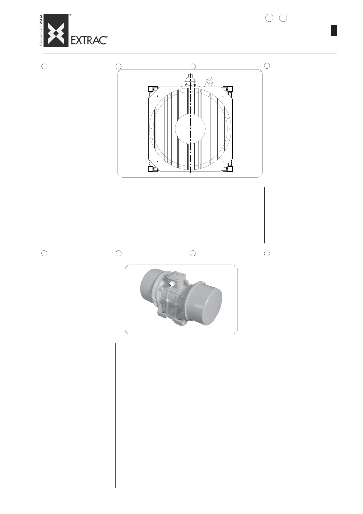
SBB
-
OPTIONS: SEAL - ELECTRIC VIBRAT OR VOL T AGE
-
OPTIONEN: DICHTUNG - SPANNUNG DES UNWUCHTMOT ORS
-
OPTIONS: JOINT - TENSION DU MOTOVIBRA TEUR
-
OPZIONI: GUARNIZIONE - TENSIONE MOTOVIBRAT ORE
8
9
09.07
1
WA.14 T.
32
8 GASKET 8 DICHTUNG 8 JOINT
In field 8 of the order code it is
possible to select the type of
hopper gasket required, depending on the product to be handled;
the following options are possible:
- N: gasket made of black SBR.
- B: gasket made of white NBR
for food-grade use.
Im Feld 8 des Bestellcodes kann
man den Typ der gewünschten
Trichterdichtung passend zum
Schüttgut wählen, welches zu
handeln ist. Es bestehen folgende
Optionen:
- N: Dichtung aus Werkstoff SBR
in schwarzer Farbe.
- B: Dichtung aus NBR in weißer
Farbe (lebensmitteltauglich).
Dans le champ 8 du code de
commande on peut choisir le type
de joint de trémie désiré en fonction du produit à traiter ; les options suivantes sont disponibles :
- N: Joint en matériau SBR couleur noir.
- B: joint en NBR couleur blanc à
usage alimentaire.
8 GUARNIZIONE
Nel campo 8 del codice di ordinazione è possibile scegliere il tipo
di guarnizione tramoggia desiderato in funzione del prodotto che
si dovrà trattare; sono disponibili
le seguenti opzioni:
- N: guarnizione in materiale SBR
di colore nero.
- B: guarnizione in NBR di colore
bianco idoneo ad uso alimentare.
9 ELECTRIC VIBRATOR
VOLTAGE
In field 9 of the order code it is
possible to select the voltage and
frequency of the electric vibrator motor from the following options:
- +: without
- 1: 230/400V 50Hz
- 5: 254/440V 60Hz
- 6: 220/380V 60Hz
- F: 330/575V 60Hz
- H: 290/500V 50Hz
- P: 230/460V 60Hz
electric vibrator with special voltages and frequencies are available on request.
9 SP ANNUNG DES
UNWUCHTMOTORS
Im Feld 9 des Bestellcodes kann
man die Spannung und die Frequenz des elektrischen Unwuchtmotors unter folgenden
Optionen wählen:
- +: ohne
- 1: 230/400V 50Hz
- 5: 254/440V 60Hz
- 6: 220/380V 60Hz
- F: 330/575V 60Hz
- H: 290/500V 50Hz
- P: 230/460V 60Hz
Auf Anfrage sind auch Unwuchtmotoren mit spezieller
Spannung und Frequenz erhältlich.
9 TENSION DU
MOTOVIBRA TEUR
Dans le champ 9 du code de
commande on peut choisir la tension et la fréquence du motovibrateur électrique parmi les options suivantes :
- +: sans
- 1: 230/400V 50Hz
- 5: 254/440V 60Hz
- 6: 220/380V 60Hz
- F: 330/575V 60Hz
- H: 290/500V 50Hz
- P: 230/460V 60Hz
Sur demande on peut avoir des
motovibrateurs avec des voltages et fréquences spécifiques.
9 TENSIONE
MOTOVIBRA T ORE
Nel campo 9 del codice di ordinazione è possibile scegliere la tensione e la frequenza del motovibratore elettrico tra le seguenti opzioni:
- +: senza
- 1: 230/400V 50Hz
- 5: 254/440V 60Hz
- 6: 220/380V 60Hz
- F: 330/575V 60Hz
- H: 290/500V 50Hz
- P: 230/460V 60Hz
A richiesta si possono avere motovibratori con voltaggi e frequenze speciali.
SAFETY CABLE
Each vibrator is provided with a
safety cable, which connects
the vibrator to the FIBC cone in
order to prevent accidental falling in the event of breakage of
the fixing feet.
SICHERHEITSKABEL
Jeder Unwuchtmotor ist mit einem
Sicherheitskabel ausgestattet,
das den Unwuchtmotor mit dem
Auslaufkonus der Big-BagEntleerstation verbindet, damit bei
einem etwaigen Bruch der
Standbeine ein Herunterfallen
desselben verhindert wird.
CABLE DE SÉCURITÉ
Chaque vibrateur est équipé d’un
câble de sécurité qui relie le vibrateur au cône du vide BIG-BAG
de manière à éviter sa chute accidentelle en cas de rupture des
pieds de fixation.
CAVO DI SICUREZZA
Ciscun vibratore è dotato di un
cavo di sicurezza che collega il
vibratore al cono dello svuota BIGBAG in modo da impedirne la caduta accidentale in caso di rottura dei piedi di fissaggio.
Page 37

SBB
-
OPERATION NOISE
-
BETRIEBSGERÄUSCHE
-
BRUY ANCE
-
RUMOROSITÀ
WA.14 T.
09.07
1
33
OPERATION NOISE
The noise level values, expressed in dB(A) are obtained
from readings made in an open
field, at maximum performance,
on 4 cardinal points at a distance of 1.5 metres from the
machine.
The values obtained are:
max. 75 dB(A)
The user may obtain values different from those indicated depending on the environment in
which the machine is installed.
It is therefore advisable to avoid
installing the machine near corners, walls and boxed metal
structures.
BETRIEBSGERÄUSCHE
Die Lärmpegelwerte, ausgedrückt in dB(A), resultieren aus
Freifeldmessungen bei maximaler Leistungsstufe, in den 4 Himmelsrichtungen, in 1,5 Meter
Abstand von der Maschine.
Meßwerte:
max. 75 dB(A)
Der Betreiber kann je nach der
Positionierung der Maschine im
Raum andere Werte ermitteln.
Daher die Maschine nicht in
Ecken, nahe an Wänden oder
Metallstrukturen aufstellen.
NIVEAU SONORE
Les valeurs du niveau sonore,
exprimées en dB(A) sont obtenues à travers des lectures en
champ libre, au rendement maximum, sur les 4 points cardinaux
à 1,5 mètres de la machine.
Valeurs mesurées:
max. 75 dB(A)
L’utilisateur pourrait relever des
valeurs différentes de celles
indiquées en fonction de l' emplacement de la machine.
Il est préférable d'éviter de placer la machine à proximité des
angles, murs, structures métalliques en caisson.
RUMOROSITÀ
I valori di rumorosità, espressi
in dB (A) sono ottenuti attraverso letture eseguite in campo libero, al massimo rendimento,
sui 4 punti cardinali a 1,5 metri
dalla macchina.
I valori rilevati sono:
dB(A) max. 75
L’ utilizzatore potrebbe rilevare
valori diversi da quelli indicati in
funzione della collocazione ambientale.
Pertanto è preferibile evitare di
collocare la macchina in prossimità di angoli, pareti, strutture
metalliche cassonate.
Page 38
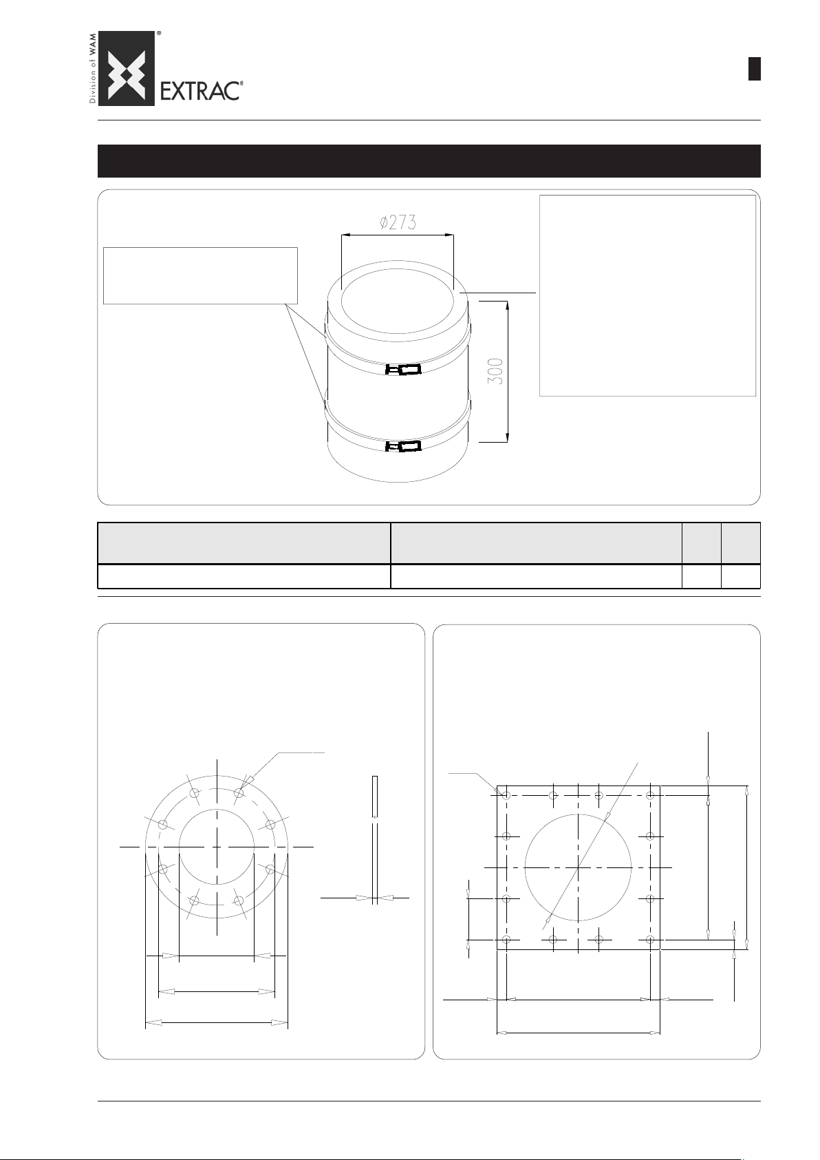
-
ACCESSORIES
-
SBB
ZUBEHÖR
-
ACCESSOIRES
-
ACCESSORI
FLEXIBLE ATTACHMENT KIT - SCHLAUCHVERBINDUNG
KIT LIAISON FLEXIBLE - KIT COLLEGAMENTO FLESSIBILE
Attachment made of:
- Black rubber
- Food-grade white rubber
WA.14 T.
09.07
1
34
Metal hose clamps Ø 273
Metallschellen Ø 273
Colliers métalliques serre-tube Ø 273
Fasce metalliche stringitubo Ø 273
CODE
BLACK RUBBER - SCHWARZER GUMMI
CAOUTCHOUC NOIR - GOM MA NERA
XJN 273236 X JN 273136 273 300
ROUND FLANGE XKF 34._
RUNDFLANSCH XKF 34._
BRIDE RONDE XKF 34._
FLANGIA TONDA XKF 34._
Schlauch aus
- schwarzem Gummi
•
•
•
WHITE RUBBER - WEISSER GUMM I
CAOUTCHOUC BLANC - GOMMA BIANCA
- weißem, nahrungsmittelechtem Gummi
Raccord en:
- Caoutchouc noir
- Caoutchouc blanc à usage alimentaire
Raccordo in:
-Gomma nera
-Gomma bianca per uso alimentare
CODE
Ø L
SQUARE FLANGE XKF 74._
QUADRATFLANSCH XKF 74._
BRIDE CARRÉE XKF 74._
FLANGIA QUADRA XKF 74._
ø 273
ø 300
ø 328
ø 14
5
ø 12.5
7
2
ø
15.5
330
361
7
110
15.5
330 15.5
361
15.5
Page 39
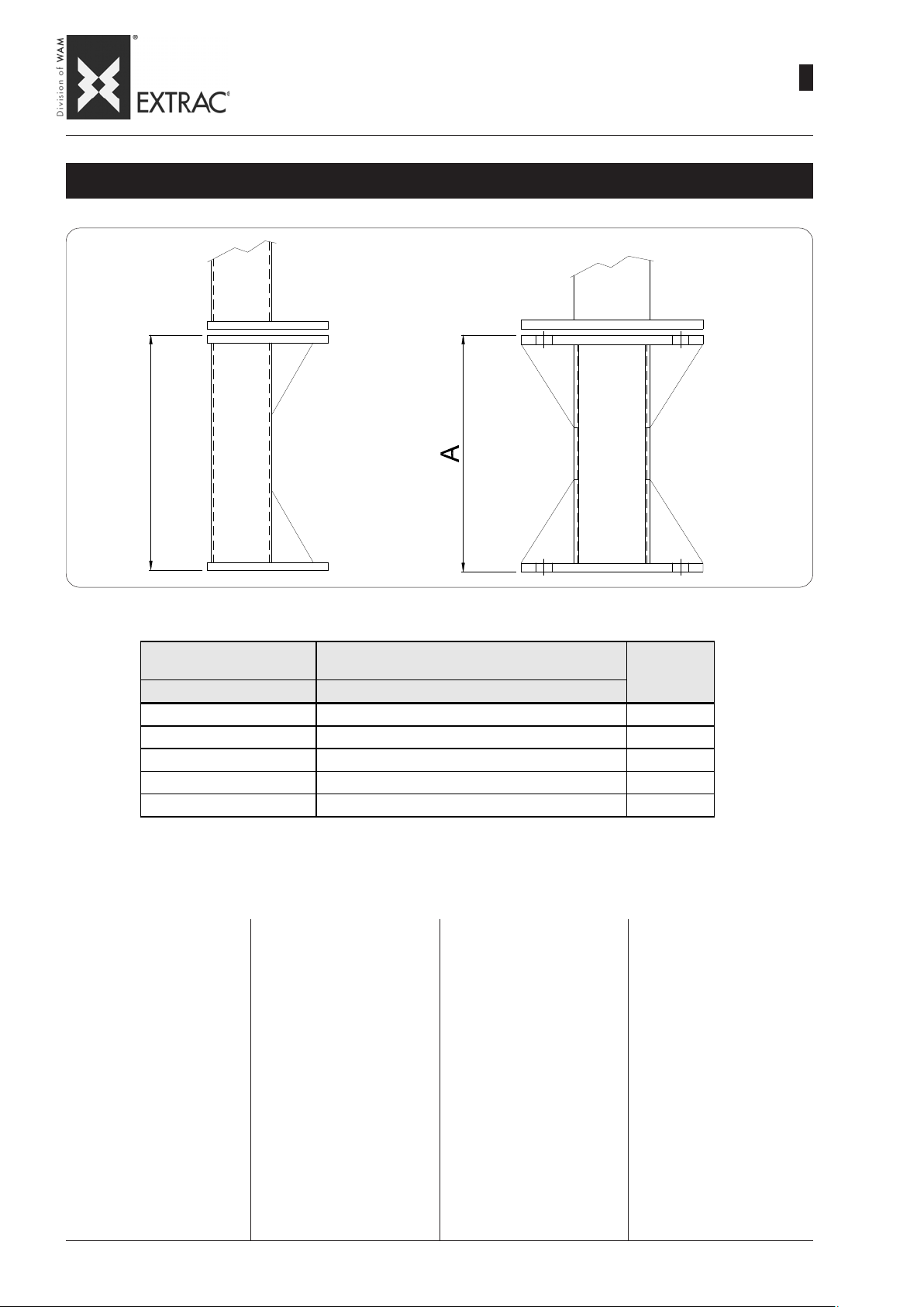
A
SBB
-
ACCESSORIES
-
ZUBEHÖR
-
ACCESSOIRES
-
ACCESSORI
FEET EXTENSIONS - FUSSVERLÄNGERUNGEN
PIEDS DE REHAUSSE - PIEDI DI RIALZO
WA.14 T.
09.07
1
35
SBB125C - SBB125S SBB150C - SBB125M - SBB150S
Code Code
KF_SBB12510 KF_SBB15010 100
KF_SBB12515 KF_SBB15015 150
KF_SBB12520 KF_SBB15020 200
KF_SBB12525 KF_SBB15025 250
KF_SBB12530 KF_SBB15030 300
NOTE:
The kit comprises four feet.
THE FOUNDATION PLAN REMAINS UNCHANGED
Materials available:
- Carbon steel
- AISI 304L
HINWEIS:
Der Bausatz besteht aus 4 Füßen.
DER FUNDAMENTPLAN BLEIBT
UNVERÄNDERT
Erhältliche Werkstoffe:
- Normstahl
- Edelstahl 1.4307
REMARQUES :
Le kit est composé de 4 pieds
LE PLAN D'ANCRAGE EST LE
MÊME
Matériaux disponibles :
- Acier au carbone
- AISI 304L
A
mm
NOTE:
Il kit è composto da n°4 piedi
LA PIANT A DI FISSAGGIO RIMANE INVARIATA
Materiali disponibili:
- Acciaio al carbonio
- AISI 304L
Page 40
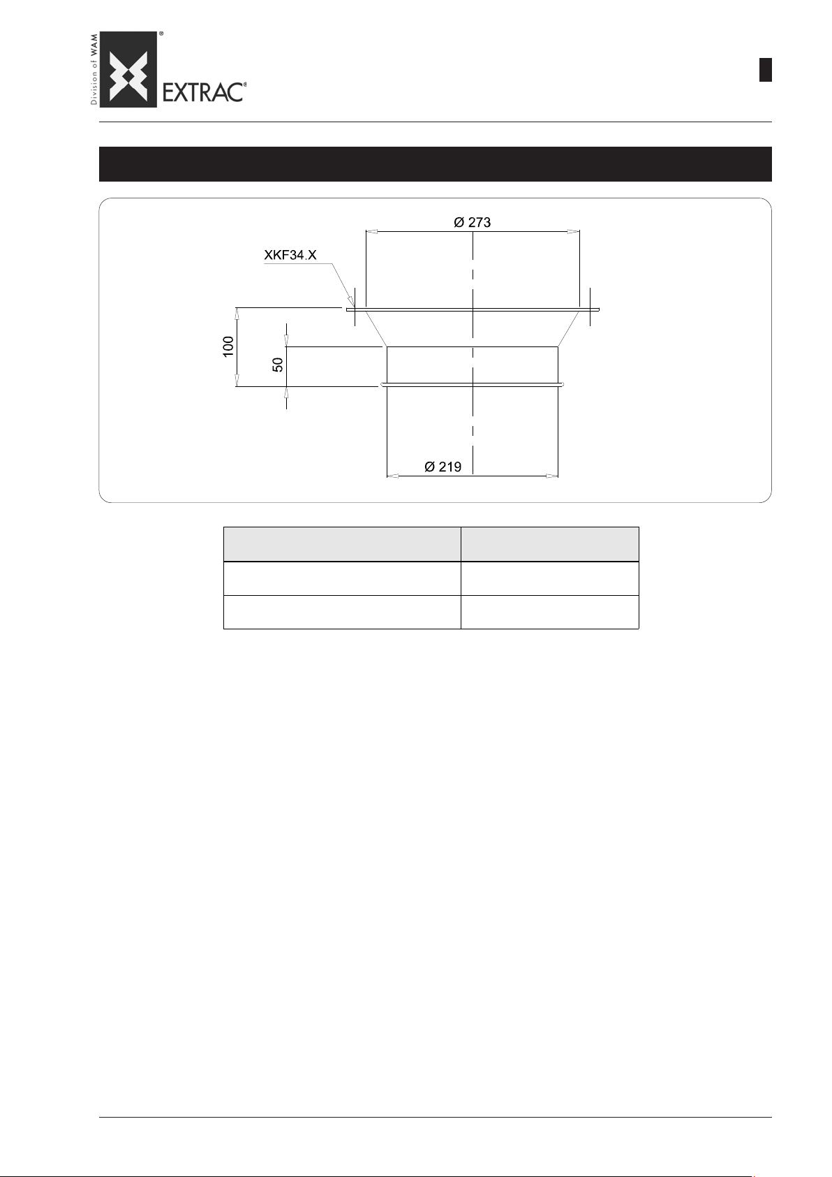
SBB
-
ACCESSORIES
-
ZUBEHÖR
-
ACCESSOIRES
-
ACCESSORI
WA.14 T.
09.07
1
36
TRONÇON DE RÊDUCTION POUR BOUCHE DE SORTIE - TRONCHETTO DI RIDUZIONE PER BOCCA SCARICO
REDUCTION SECTION FOR OUTLET SPOUT - STUTZEN ZUR AUSLUAFREDUZIERUNG
MATERIAL - WERKSTOFF
MATÉRIAU - MATERIALE
Carb on steel - Stahl
Acier au carbone - Acciai o a l carbon i o
AISI 304
1.4301
Code
KMR2732191001
KMR2732191002
Page 41
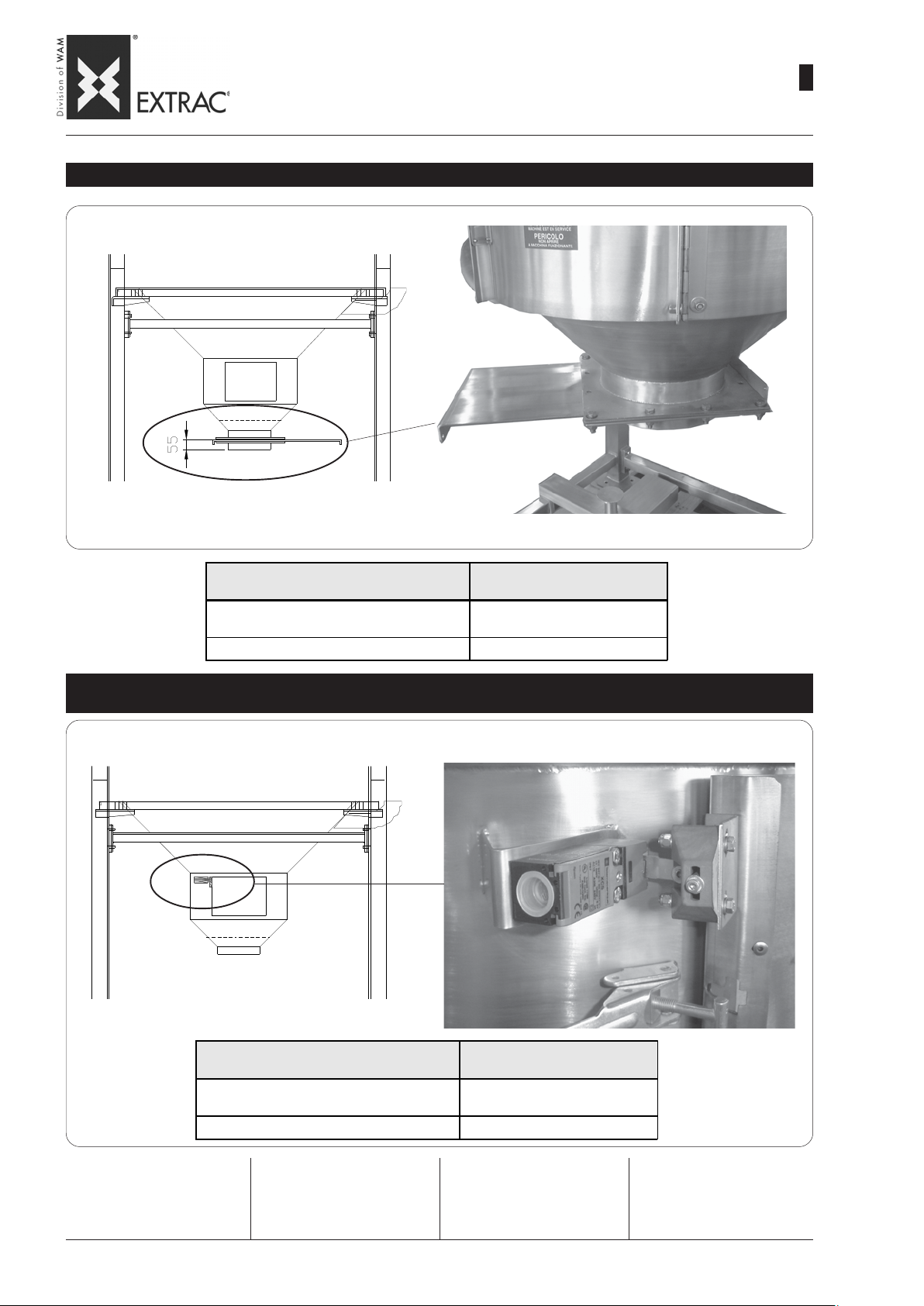
-
ACCESSORIES
-
SBB
MANUAL GATE VALVE - HANDSCHIEBER - VANNE MANUELLE - SERRANDA MANUALE
ZUBEHÖR
-
ACCESSOIRES
-
ACCESSORI
WA.14 T.
09.07
1
37
MATERIAL - WERKSTOFF
MATÉRIAU - M ATERIALE
Carb on steel - Stahl
Acier au carbone - Acciai o al carbonio
AISI 304L
DOOR OPEN MECHANICAL LIMIT STOP - MECHANISCHER ENDSCHALTER KLAPPE OFFEN
FIN DE COURSE MECANIQUE D’OUVERTURE DU PORTILLON - FINE CORSA MECCANICO APERTURA A PORTELLO
Code
KSMSBB2731A
KSMSBB2732A
Acier au carbone - Acciai o al carbonio
Useful for impeding activation of
the vibrator if the valve is not
closed correctly.
MATERIAL - WERKSTOFF
MATÉRIAU - MATERIALE
Ca rbon steel - Stahl
AISI 304L
Dient zum Hemmen der Betätigung des Unwuchtmotors, wenn
die Klappe nicht korrekt geschossen ist.
Code
KFMSBB1A
KFMSBB2A
Empêche l’activation du vibrateur
en cas de portillon non fermé
correctement.
Utile per inibire l’attivazuine del
vibratore nel caso il portello non
fosse correttamente chiuso.
Page 42
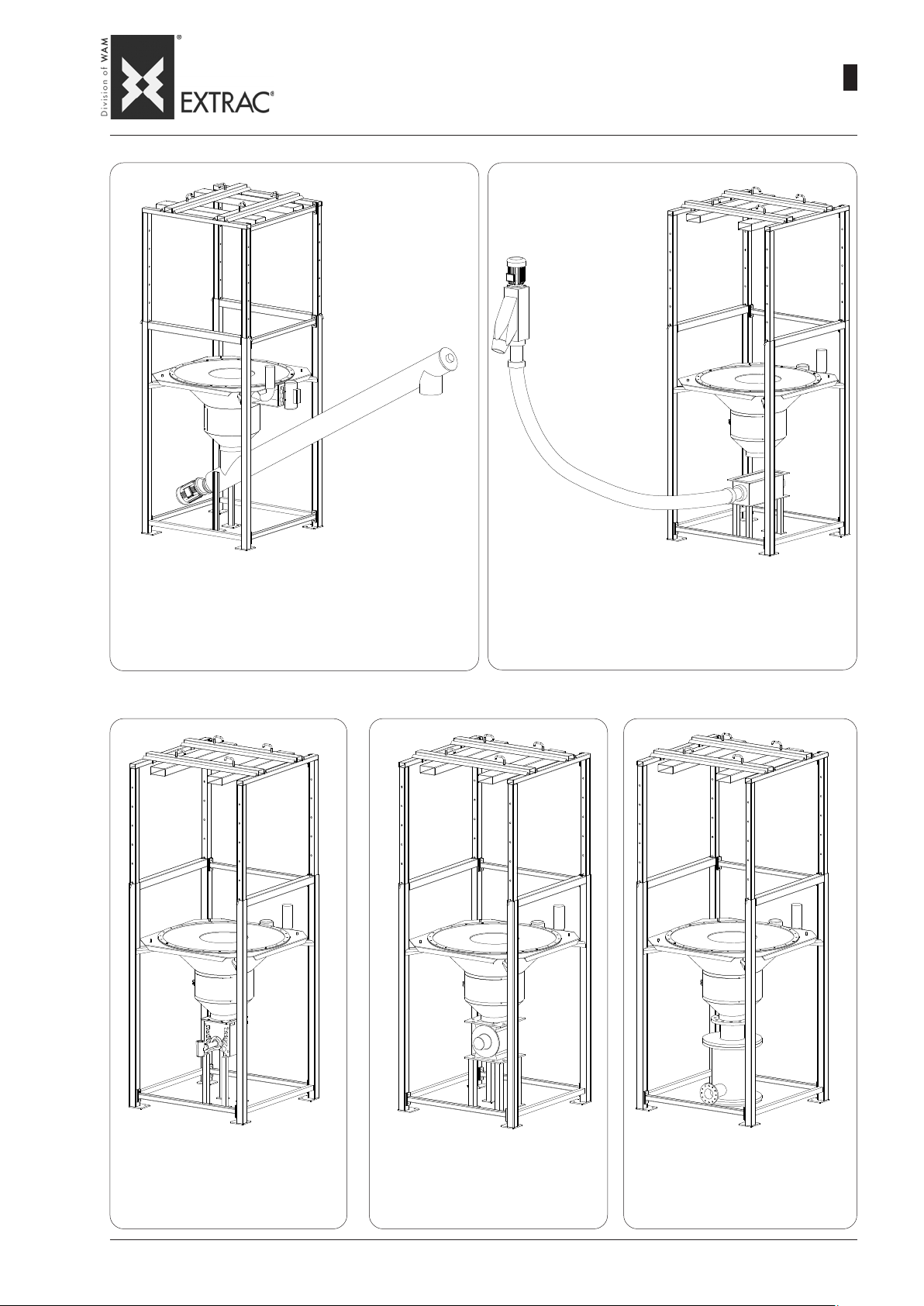
SBB
-
APPLICATIONS
-
ANWENDUNGEN
-
APPLICATIONS
-
APPLICAZIONI
WA.14 T.
09.07
1
38
SBB + INCLINED SCREW FEEDER
SBB + SCHRÄGSCHNECKE
SBB + VIS D'EXTRACTION INCLINÉE
SBB + COCLEA ESTRATTRICE INCLINATA
SBB + FLEXIBLE SCREW
SBB + FLEXIBLE SCHNECKE
SBB + VIS FLEXIBLE
SBB + COCLEA FLESSIBILE
SBB + ROT AR Y VALVE
SBB + ZELLENRADSCHLEUSE
SBB + VANNE ALVÉOLAIRE
SBB + ROTOVALVOLA
SBB + MICRO-BATCH FEEDER
SBB + MIKRODOSIERER
SBB + MICRODOSEUR
SBB + MICRODOSATORE
SBB + PNEUMATIC CONVEYING
SBB + PNEUMATISCHE FÖRDERUNG
SBB + TRANSPORT PNEUMA TIQUE
SBB + TRASPORTO PNEUMATICO
Page 43
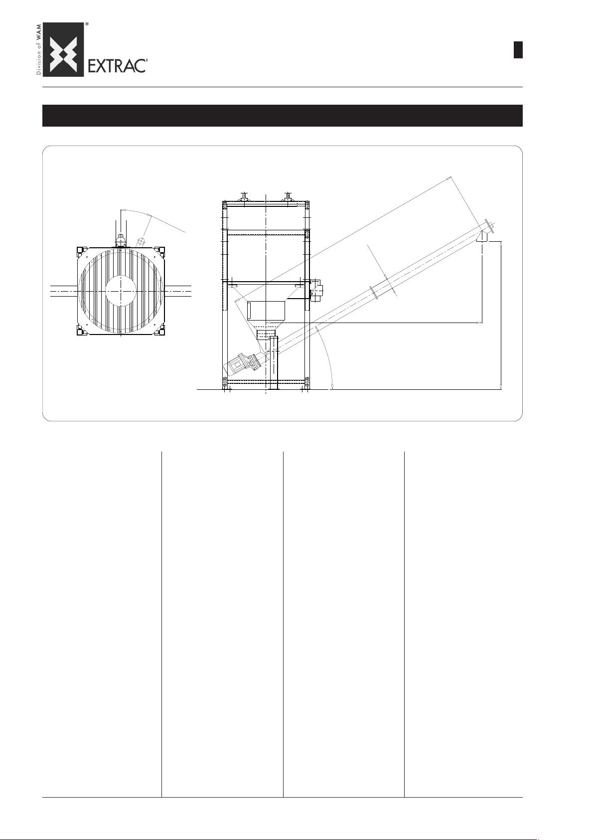
-
APPLICATIONS
-
SBB
SBB with Ø 168 tubular screw conveyor - SBB mit Rohrschnecke Ø 168
SBB avec vis sans fin tubulaire Ø 168 - SBB con coclea tubolare Ø 168
SCREW CONVEYOR OUTLET ORIENTATION
AUSRICHTUNG SCHNECKENAUSLAUF
ORIENTATION SORTIE VIS
ORIENTAMENTO USCITA COCLEA
ANWENDUNGEN
-
APPLICATIONS
-
APPLICAZIONI
WA.14 T.
09.07
1
39
N
E
LOAD SIDE
AUFGABESEITE
CÔTÉ CHARGEMENT
LATO CARICO
INCLINED SCREW FEEDER
For this application it is advisable to use:
Ø168 tubular screw conveyor
complete with:
- tapered inlet spout Ø168/Ø273.
- drive unit at inlet end.
- supporting base XJP168031.
- Ø273 flexible rubber sleeve
300mm long complete with hose
clamp.
2
2
.
5
°
W
SCHRÄGSCHNECKE
Für diese Anwendung sollte folgende Version eingesetzt werden:
Rohrschnecke Ø168 komplett
mit:
- Konischer Einlauf Ø168/Ø273.
- Antrieb einlaufseitig.
- Bodenstütze XJP168031.
- Gummimanschette Ø273, Länge 300 mm komplett mit
Schlauchschellen.
0
0
0
4
3
0
°
VIS INCLINEE
Pour cette application il est conseillé d'utiliser:
vis tubulaire Ø168 équipée de:
- bouche d'entrée conique Ø168/
Ø273.
- motorisation en entrée.
- support de soutien mod.
XJP168031.
- manchon flexible en caoutchouc Ø273, long. 300 mm avec
colliers serre-tube.
Ø
1
6
8
3464
COCLEA INCLINATA
Per questa applicazione si consiglia di utilizzare:
coclea tubolare Ø168 completa
di:
- bocca carico conica Ø168/
Ø273.
- motorizzazione al carico.
- supporto di sostegno mod.
XJP168031.
- calzone flessibile di gomma
Ø273 lunghezza 300mm completo di fascette stringitubo.
2370
The length of the screw conveyor must be defined on the basis
of the plant requirements, with
maximum inclination angle of 30°
(to be specified in the order
phase).
The drawing represents an example of a 4000mm long screw
conveyor.
However, it is the Custo-mer's
responsibility to fix the final part
of the screw conveyor rigidly.
Die Schneckenlänge ist in bezug
auf die Anlagenanfor-derungen
auszulegen, mit einem max. Einbauwinkel von 30° (in der Bestellung anzugeben).
In der Abbildung ist als Beispiel
eine Schnecke von 4000 mm
Länge dargestellt.
Die fachgerechte Befestigung
des Auslaufteils der Schnecke
ist bauseitig vorzunehmen.
La longueur de la vis doit être
déterminée en fonction des exigences de production, avec un
angle d'inclinaison maximum de
30° (à préciser lors de la commande).
Le dessin illustre un exemple de
vis d'une longueur de 4000 mm.
La fixation rigide de la partie finale de la vis est à la charge du
Client.
La lunghezza della coclea dovrà
essere definita in funzione delle
esigenze impiantistiche, con angolo di inclinazione massimo di
30° (da precisare in fase d'ordine).
Il disegno rappresenta una coclea lunga 4000mm come esempio.
Rimane comunque a carico del
Cliente il fissare rigidamente la
parte finale della coclea.
Page 44
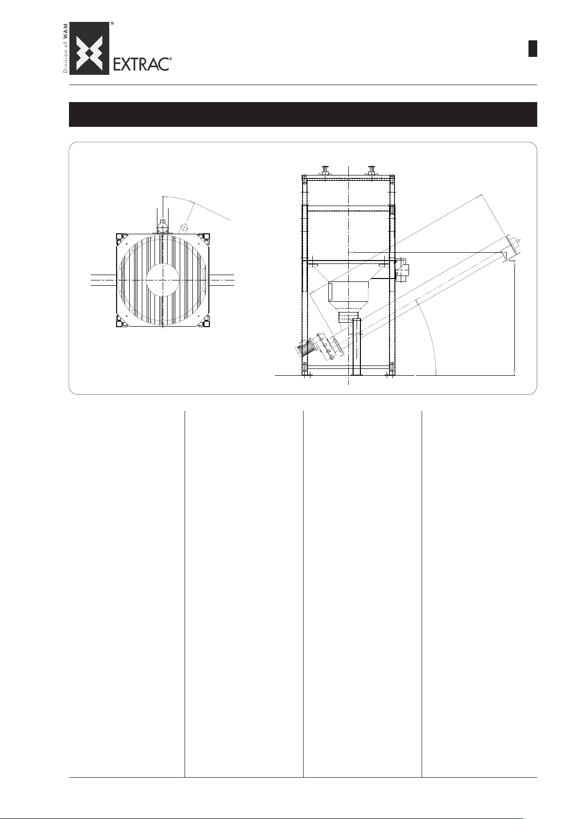
-
APPLICATIONS
-
SBB
SBB with Ø 150 trough screw conveyor - SBB mit Trogschnecke Ø 150
SBB avec vis en auge Ø 150 - SBB con coclea a canala Ø 150
SCREW CONVEYOR OUTLET ORIENTATION
AUSRICHTUNG SCHNECKENAUSLAUF
ORIENTATION SORTIE VIS
ORIENTAMENTO USCITA COCLEA
N
ANWENDUNGEN
-
APPLICATIONS
-
APPLICAZIONI
2
2
.
5
°
0
0
3
2380
09.07
1
WA.14 T.
0
40
E
LOAD SIDE
AUFGABESEITE
CÔTÉ CHARGEMENT
LATO CARICO
INCLINED SCREW FEEDER
For this application it is advisa-
ble to use:
Ø150 trough screw conveyor
complete with:
- tapered inlet spout
Ø150/Ø 273.
- drive unit at inlet end.
- supporting base XJP168031.
- Ø 273 flexible rubber sleeve
300 mm long complete with
hose clamps.
The length of the screw must
be defined on the basis of the
plant requirements, with maximum inclination angle of 30° (to
be specified in the order phase).
The drawing represents an example of a 3000mm long screw
conveyor, with outlet spout.
However, it is the Customer's
responsibility to fix the final part
of the screw conveyor rigidly.
W
SCHRÄGSCHNECKE
Für diese Anwendung sollte folgende Version eingesetzt werden:
Trogschnecke Ø150 komplett
mit:
- Konischer Einlauf Ø150/Ø273.
- Antrieb einlaufseitig.
- Bodenstütze XJP168031.
- Gummimanschette Ø 273, Länge 300 mm komplett mit
Schlauchschellen.
Die Schneckenlänge ist in bezug auf die Anlagenanfor- derungen auszulegen, mit einem
max. Einbauwinkel von 30° (in
der Bestellung anzugeben).
In der Abbildung ist als Beispiel
eine Schnecke von 3000 mm
Länge dargestellt.
Die fachgerechte Befestigung
des Auslaufteils der Schnecke
ist bauseitige vorzunehmen.
VIS INCLINÉE
Pour cette application il est conseillé d'acheter:
vis en auge Ø 150 équipée de:
- bouche d'entrée conique
Ø 150/Ø 273.
- motorisation en entrée.
- support de soutien mod.
XJP168031.
- manchon flexible en caoutchouc Ø 273, long. 300mm
avec colliers serre-tube.
La longueur de la vis doit être
déterminée en fonction des exigences de production, avec un
angle d'inclinaison maximum de
30° (à préciser lors de la commande).
Le dessin illustre un exemple de
vis d'une longueur de 3000 mm,
avec bouche de sortie de tête.
La fixation rigide de la partie finale de la vis est à la charge du
Client.
3
0
°
COCLEA INCLINATA
Per questa applicazione si consiglia di acquistare:
coclea a canala Ø 150 completa
di:
- bocca carico conica
Ø150/Ø 273.
- motorizzazione al carico.
- supporto di sostegno mod.
XJP168031.
- calzone flessibile di gomma Ø
273 lunghezza 300 mm completo di fascette stringitubo.
La lunghezza della coclea dovrà essere definita in funzione
delle esigenze impiantistiche,
con angolo di inclinazione massimo di 30° (da precisare in fase
d'ordine).
Il disegno rappresenta una coclea lunga 3000mm, con bocca
di scarico di testa, come esempio.
Rimane comunque a carico del
Cliente il fissare rigidamente la
parte finale della coclea.
1730
Page 45

N.B. Rights reserved to modify technical specifications
N.B. Angaben ohne Gewähr. Änderungen können ohne Vorankündigung vorgenommen werden.
N.B. Toutes données portées dans le présent catalogue n’engagent pas le fabricant. Elles peuvent être modifiéès à tout moment.
N.B. Tutti i dati riportati nel presente catalogo non sono impegnativi e possono subire variazioni in qualsiasi momento.
WAM S.p.A. - EXTRAC Division
Via Cavour, 338
I - 41030 Ponte Motta
Cavezzo (MO) - ITALY
fax
e-mail
internet
videoconferenze
+ 39 / 0535 / 618111
+ 39 / 0535 / 618226
[email protected]
www.wamgroup.com
+ 39 / 0535 / 49032
Page 46
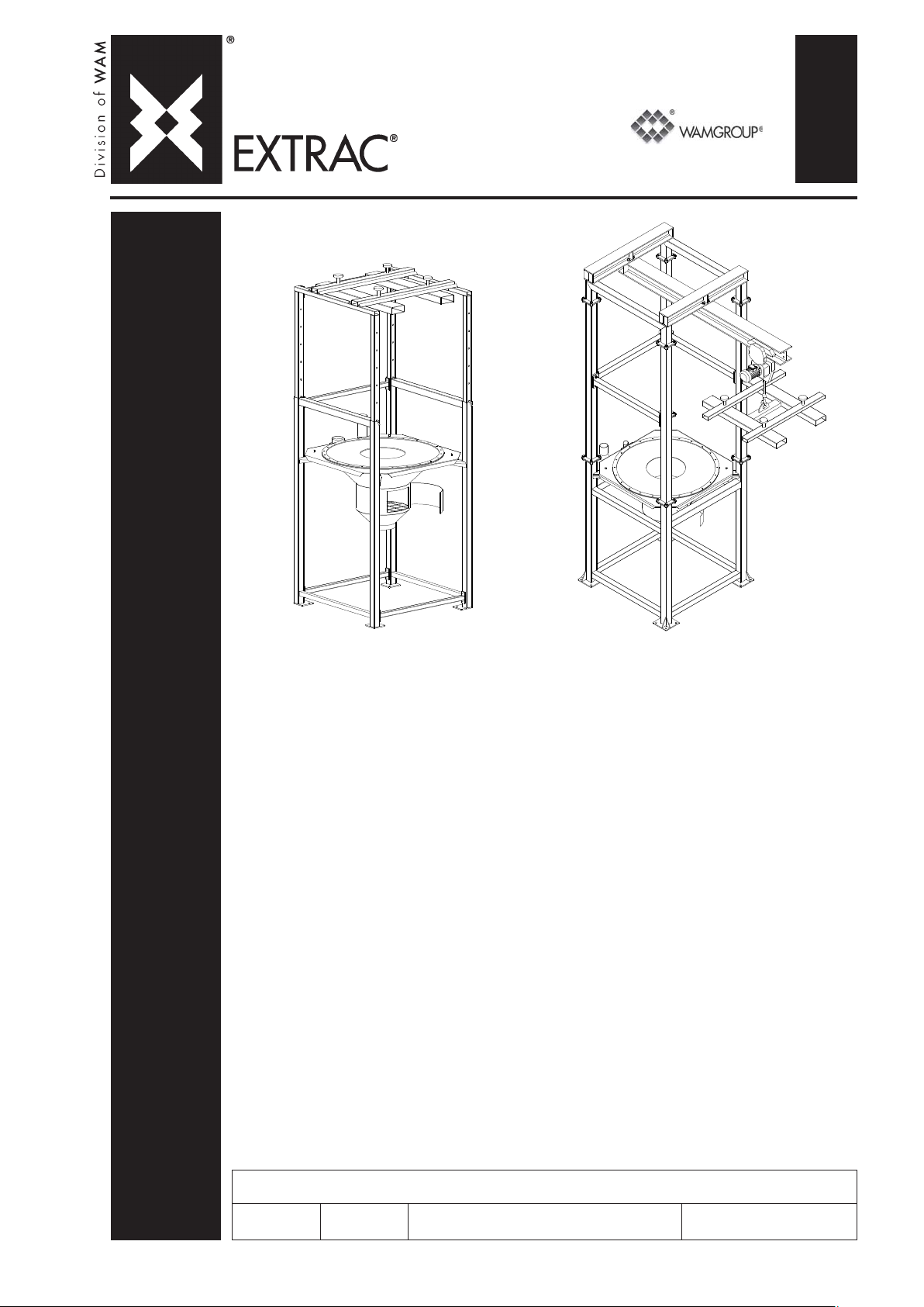
2
• FLEXIBLE INTERMEDIATE BULK CONTAINER UNLOADER
INST ALLA TION, OPERATION AND MAINTENANCE
• BIG-BAG - ENTLEERSTATION
EINBAU-, BETRIEBS- UND WARTUNGSANLEITUNG
MAINTENANCE
• VIDE-SACS DE GRANDES DIMENSIONS
INST ALLATION, UTILISA TION ET ENTRETIEN
• SVUOTA BIG BAG
INSTALLAZIONE, USO E MANUTENZIONE
CAT ALOGUE No. W A.14 M.
SBB
ISSUE
A4
All rights reserved © WAMGROUP
CIRCULATION
100
LA TEST UPDA TE
09.07
Page 47
All the products described in this catalogue are manufactured according to WAM® S.p.A. Quality System
0
procedures.
The Company’s Quality System, certified in July 1994 according to International S tandards UNI EN ISO 9002-94 and
extended to UNI EN ISO 9001-2000 in October, 2002, ensures that the entire production process, starting from the
processing of the order to the technical service after delivery, is carried out in a controlled manner that guarantees
the quality standard of the product.
Alle in diesem Katalog beschriebenen Erzeugnisse werden in Konformität mit dem Qualitätssystem der WAM
S.p.A. hergestellt.
Das im Juli 1994 zertifizierte Qualitätssystem entspricht der Norm UNI EN ISO 9002-94 (im Oktober 2002 auf
UNI EN ISO 9001-2000 erweitert) und gewährleistet dem Kunden eine strenge Qualitätskontrolle in jeder Phase
des Produktionprozesses bis hin zum Kundendienst nach Auslieferung der Ware.
Tous les produits décrits dans ce catalogue ont été réalisé selon les modalités opérationnelles définies Système
de Qualité de WAM® S.p.A.
Le système de Qualité de l’entreprise, certifié au mois de juillet 1994 en conformité aux Normes Internationales UNI
EN ISO 9002-94 et successivement étendu à UNI EN ISO 9001-2000 au mois de octobre 2002, est en mesure
d’assurer que le procédé entier de production, à partir de la formulation de la commande jusqu’au service technique
après la livraison, soit effectué de manière contrôlée et appropriée afin de garantir le standard de qualité du produit.
Tutti i prodotti descritti in questo catalogo sono stati realizzati secondo modalità operative definite Sistema
Qualità di WAM® S.p.A.
Il Sistema Qualità aziendale, certificato dal luglio 1994 in conformità alle Normative Internazionali UNI EN ISO
9002-94 e successivamente esteso alle Normative Internazionali UNI EN ISO 9001-2000 nell’ottobre 2002, è in
grado di assicurare che l’intero processo produttivo, dalla formulazione dell’ordine fino all’assistenza tecnica
successiva alla consegna, venga effettuato in modo controllato ed adeguato a garantire lo standard qualitativo
del prodotto.
®
UNI EN ISO 9001-200
Certifie d Company
This publication cancels and replaces any previous edition and revision.
We reserve the right to implement midifications without notice.
This catalogue cannot be reproduced, even partially, without prior consent.
Diese Veröffentlichung annuliert und ersetzt jeder hergehende Edition oder Revision.
WAM® behält sich das Recht vor, Anderungen ohne vorherige Informationen durchzuführen.
Cette publication annule et remplace toutes les autres précédentes.
La reproduction et la publication partielle ou totale de ce catalogue est interdite sans notre autorisation.
Nous nous réservons le droit d’apporter toutes modifications à nos produits.
Questa pubblicazione annulla e sostituisce ogni precedente edizione o revisione.
Ci riserviamo il diritto di apportare modifiche senza preavviso.
E’ vietata la riproduzione anche parziale senza autorizzazione.
Page 48

SBB
INDEX
INHALTSVERZEICHNIS
INDEX
INDICE
-
09.07
WA.14.INDEX
2
MAINTENANCE CAT ALOGUE
MANUFACTURING DATA..........................................................
GENERAL STANDARDS...........................................................
OPERATING CONDITIONS........................................................
INDICATIONS FOR USE............................................................
WARNINGS..............................................................................
DESCRIPTION AND USE...........................................................
WARRANTY CONDITIONS.......................................................
TRANSPORT AND STORAGE..................................................
PAKING AND WEIGHTS............................................................
STORING THE MACHINE...........................................................
PACKING - UNPACKING...........................................................
HANDLING...............................................................................
INSTALLATION - ANCHORING ..................................................
INST ALLA TION - ASSEMBLY OF MODEL S..............................
INSTALLATION - ASSEMBLY OF MODEL M..............................
ELECTRICAL CONNECTIONS...................................................
ELECTRIC -PNEUMA TIC ACTUA TORS CONNECTION................
START-UP.................................................................................
START-UP - OPERA TION..........................................................
STAR T-UP - ADJUSTING THE ELECTRIC VIBRATOR.................
STAR T-UP - PNEUMATIC ACTUATORS.....................................
MAINTENANCE - WARNING.....................................................
CLEANING................................................................................
OPERATION NOISE...................................................................
RESIDUAL RISKS.....................................................................
SCRAPPING THE MACHINE - RETURNING THE MACHINE.........
FAUL T FINDING.........................................................................
WARTUNGS KA T ALOG
KONSTRUKTIONSDATEN.....................................................
ALLGEMEINES.........................................................................
EINSATZEINSCHRÄNKUNGEN.................................................
ANGABEN ZUM GEBRAUCH...................................................
HINWEISE................................................................................
BESCHREIBUNG UND FUNKTION.............................................
GARANTIEBEDINGUNGEN.......................................................
TRANSPORT UND EINLAGERUNG ...........................................
VERPACKUNGEN UND GEWICHTE...........................................
LAGERHALTUNG....................................................................
VERP ACKUNG - AUSPACKEN.................................................
HANDLING...............................................................................
INSTALLATION - BEFESTIGUNG..............................................
INSTALLA TION - ZUSAMMENBAU MODELL S.........................
INSTALLA TION - ZUSAMMENBAU MODELL M.........................
ELEKTRISCHE ANSCHLÜSSE..................................................
ELEKTRISCHER UND PNEUM. ANSCHLÜSS DER AUSTRAG ....
INBETRIEBNAHME...................................................................
INBETRIEBNAHME - BETRIEB..................................................
INBETRIEBNAHME - EINSTELLUNG DES UNWUCHTMOTORS..
INBETRIEBNAHME - PNEUMATISCHE AUSTRAGHILFEN...........
WARTUNG - HINWEISE...........................................................
REINIGUNG..............................................................................
BETRIEBSGERAUSCHE...........................................................
RESTRISIKEN..........................................................................
VERSCHROTTEN DER MASCHINE - MASCHINENRÜCKG .........
BETRIEBSSTÖRUNGEN UND ABHILFE.....................................
M.01
.02
.03
.04
.05
.06 →.08
.09
.10
.11
.12
.13
.14
.15
.16
.17→.20
.21
.22→.30
.31
.32→.33
.34
.35→.37
.38→.40
.41
.42
.43
.44
.45
2
CAT ALOGUE D’ENTRETIEN
DONNÉES COSTRUCTIVES......................................................
CONSIGNES GENERALES........................................................
LIMITES D’EMPLOI....................................................................
MODE D’EMPLOI......................................................................
RECOMMANDATIONS..............................................................
DESCRIPTION ET DOMAINE D’UTILISATION..............................
CONDITIONS DE GARANTIE.....................................................
TRANSPORT ET EMMAGASINAGE..........................................
EMBALLAGES ET POIDS.........................................................
EMMAGASINAGE.....................................................................
EMBALLAGE DEBALLAGE......................................................
MANUTENTION........................................................................
INSTALLATION - NORMES DE FIXA TION..................................
INSTALLA TION - ASSEMBLAGE MODELE S.............................
INSTALLA TION - ASSEMBLAGE MODELE M............................
RACCORDEMENTS ÉLECTRIQUES...........................................
RACCORDEMENT ÉLECTRIQUE-PNEUMA TIQUE DES ACTION..
MISE EN SERVICE DE LA MACHINE..........................................
MISE EN SERVICE - FONCTIONNEMENT ...................................
MISE EN SERVICE - REGLAGE DU MOTOVIBRA TEUR.............
MISE EN SERVICE - ACTIONNEURS PNEUMATIQUES...............
ENTRETIEN - RECOMMANDATIONS..........................................
NETTOYAGE............................................................................
BRUYANCE..............................................................................
RISQUES RESIDUELS...............................................................
DEMANTELEMENT DE LA MACHINE- RESTITUTION MACHINE..
RECHERCHE DES PANNES.......................................................
CAT ALOGO DI MANUTENZIONE
DATI COSTRUZIONE.............................................................
NORME GENERALI...................................................................
LIMITI DI IMPIEGO......................................................................
INDICAZIONE PER L’USO..........................................................
AVVERTENZE..........................................................................
DESCRIZIONE E FUNZIONE D’USO...........................................
CONDIZIONI DI GARANZIA.......................................................
TRASPORTO E IMMAGAZZINAGGIO.......................................
IMBALLI E PESI.........................................................................
IMMAGAZZINAGGIO................................................................
IMBALLO-RIMOZIONE..............................................................
MOVIMENTAZIONE...................................................................
INSTALLAZIONE- NORME DI FISSAGGIO.................................
INSTALLAZIONE- ASSEMBLAGGIO MODELLO S.....................
INSTALLAZIONE- ASSEMBLAGGIO MODELLO M.....................
COLLEGAMENTI ELETTRICI......................................................
COLLEGAMENTO ELETTRO-PNEUMA TICO ATTIVATORI...........
MESSA IN SERVIZIO DELLA MACCHINA..................................
MESSA IN SERVIZIO - FUNZIONAMENTO.................................
MESSA IN SERVIZIO - REGOLAZIONE MOT OVIBRA TORE.......
MESSA IN SERVIZIO - ATTIVATORI PNEUMATICI......................
MANUTENZIONE - A VVERTENZE..............................................
PULIZIA....................................................................................
RUMOROSITA’..........................................................................
RISCHI RESIDUI........................................................................
ROTTAMAZIONE MACCHINA - RESO MACCHINA....................
RICERCA GUASTI.....................................................................
M.01
.02
.03
.04
.05
.06 →.08
.09
.10
.11
.12
.13
.14
.15
.16
.17→.20
.21
.22→.30
.31
.32→.33
.34
.35→.37
.38→.40
.41
.42
.43
.44
.45
Page 49
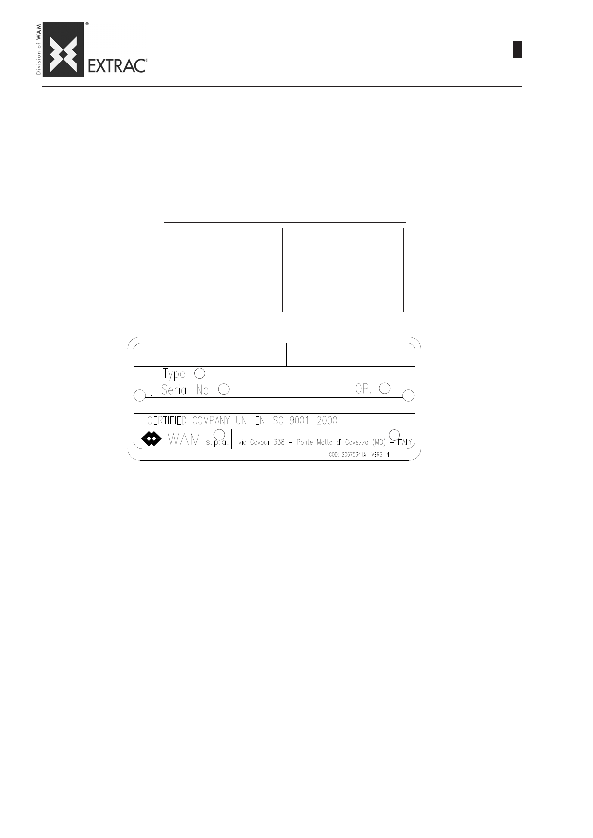
SBB
-
MANUFACTURING DA TA
-
KONSTRUKTIONSDATEN
-
DONNEES CONSTRUCTIVES
-
DATI COSTRUZIONE
09.07
WA.14 M.
2
01
ADDRESS OF LOCAL DEALER
OR SERVICE POINT
MACHINE
IDENTIFICATION
Refer to order code in acknowledgment of order, in invoice and
on packaging to identify equipment or on the label applied on
the package or on the plate affixed directly on the machine..
ANSCHRIFT DES LOKALEN
HÄNDLERS ODER KUNDENDIENSTES
IDENTIFIKATION
DER MASCHINE
Zur korrekten Identifikation des
Geräts auf den Code Bezug nehmen, der sich in der Auftragsbestätigung, der Rechnung und
dem Aufkleber auf der Verpackung oder dem Schild auf der
Maschine befindet.
1
2
ADRESSE DU REVENDEUR OU
DU SERVICE APRES-VENTE
LOCAL
IDENTIFICATION
DE LA MACHINE
Pour identifier correctement la
machine, vous devez vous référer au code qui se trouve sur
la confirmation de commande,
sur la facture ou sur l’étiquette
apposée sur l’emballage et sur
la plaque appliquée directement
sur la machine.
3
INDIRIZZO RIVENDITORE O
PUNTO DI ASSISTENZA LOCALE
IDENTIFICAZIONE
DELLA MACCHINA
Per una corretta identificazione
della macchina, bisogna fare riferimento al codice che si trova
sulla conferma d’ordine, sulla fattura o sulla etichetta posta sull’imballo e sulla targhetta direttamente applicata sulla macchina.
1) Machine code
2) Machine Serial No.
3) Assembly operator code
4) Logo of manufacturer
5) Manufacturer’s address
4
1) Gerätecode
2) Serien-Nr. des Geräts
3) Zeichen des Monteurs
4) Herstellerlogo
5) Herstelleradresse
1) Code de la machine
2) Matricule machine.
3) Code opérateur assembleur
4) Logo constructeur
5) Adresse constructeur
5
1) Codice macchina
2) Matricola macchina
3) Codice operatore assemblatore
4) Logo costruttore
5) Indirizzo costruttore
Page 50
SBB
-
GENERAL ST ANDARDS
-
ALLGEMEINES
-
CONSIGNES GÉNÉRALES
-
NORME GENERALI
09.07
WA.14 M.
2
02
SCOPE AND IMPORTANCE OF
THE MANUAL
This manual, prepared by the
manufacturer, forms an integral
part of the FIBC UNLOADER; it
must therefore accompany of the
FIBC UNLOADER right up to its
final scrapping, and must be
available ready at hand for consultation by the operators concerned and those in charge of
operations at the work site. If the
machine changes hands, this
manual must be handed over to
the new owner, as part of the
SBB supply. Before carrying out
any operation on or using the
SBB, the personnel concerned
must have read this manual carefully and completely. If the manual is lost, or in such a condition
as to make it illegible, download
a new copy from the internet site
www.wamgroup.com, and
check the date of the last revision. This manual provides warnings and indications concerning
the safety regulations for preventing accidents at the work
site. However, the operators
MUST scrupulously follow the
safety regulations meant for
them by the existing legislation.
Modifications to the safety regulations made over time must be
integrated and implemented.
ZWECK UND BEDEUTUNG DES
HANDBUCHS
Dieses vom Hersteller erstellte
Handbuch ist integrierender Teil
der BIG-BAG Entleerstation.. Daher muss es der BIG-BAG Entleerstation unbedingt folgen, bis
dieser zerlegt bzw. verschrottet
wird. Es muss zudem einfach zu
finden sein, wenn die betroffenen Bediener oder die Baustellenleitung in ihm nachschlagen
wollen. Bei einem Besitzerwechsel des SBB muss das Handbuch dem neuen Besitzer als
normale Bestückung des SBB
ausgehändigt werden. Bevor irgendwelche Arbeiten an oder mit
dem Austragboden SBB ausgeführt werden, müssen die betreffenden Personen dieses
Handbuch unbedingt mit großer
Aufmerksamkeit durchgelesen
haben. Falls das Handbuch verloren geht oder unleserlich geworden ist, kann eine neue Kopie von den Internetseiten unter
www.wamgroup.com her-untergeladen werden, nachdem
man das Datum der letzten Aktualisierung des Handbuchs geprüft hat. Dieses Handbuch liefert Hinweise und Angaben zu
den Sicherheits- und Unfallverhütungsbestimmungen am Arbeits-platz. Die Sicherheitsbestimmungen, die laut den geltenden Normen vom Bedienungspersonal zu beachten sind, müssen zu jedem Zeitpunkt beachtet
wer-den.
Etwaige Änderungen der Sicherheitsbestimmungen, die im
Laufe der Zeit vorgenommen
werden, sind immer zu erfassen
und umzusetzen.
BUT ET IMPORTANCE DU MANUEL
Le présent Manuel, rédigé par le
constructeur, fait partie intégrante de la fourniture du vide BIGBAG. Il doit absolument suivre le
vide BIG-BAGS jusqu’à son démantèlement et être à portée de
la main pour une consultation rapide de la part des opérateurs
concernés et par la direction
des travaux du chantier. En cas
de changement de propriété de
la machine, le manuel doit être
remis au nouveau propriétaire,
comme équipement du SBB.
Avant d’effectuer une quelconque opération avec ou sur le
SBB, le personnel concerné doit
absolument et obligatoirement
avoir lu très attentivement le présent manuel. Si le manuel est
égaré, abîmé de manière à ne
plus être lisible, une copie doit
être téléchargée à partir du site
internet www.wamgroup.com
en vérifiant la date de la dernière mise à jour.
Le présent manuel fournit les recommandations et les indications
concernant les consignes de sécurité pour la prévention contre
les accidents du travail. Dans
tous les cas les consignes de
sécurité conformément aux normes en vigueur doivent être observée avec la plus grande attention par les différents opérateurs.
Les modifications éventuelle des
consignes de sécurité devront
être adoptées et mises en
oeuvre.
SCOPO ED IMPORTANZA DEL
MANUALE
Il presente manuale, redatto dal
costruttore, è parte integrante
del corredo dello svuota BIGBAG; come tale deve assolutamente seguire lo svuota BIGBAG fino al suo smantellamento
ed essere facilmente reperibile
per una rapida consultazione da
parte degli operatori interessati
e della direzione lavori del cantiere. In caso di cambio di proprietà della macchina, il manuale
deve essere consegnato alla
nuova proprietà, quale corredo
dello stesso SBB. Prima di eseguire qualsiasi operazione con,
o sul SBB, il personale interessato deve assolutamente ed obbligatoriamente aver letto con la
massima attenzione il presente
manuale. Qualora il manuale venga smarrito, sgualcito e tale da
non essere leggibile, si deve scaricare una nuova copia dal sito
internet www.wamgroup.com e
verificarne la data dell’ultimo aggiornamento. Il presente manuale fornisce avvertenze ed indicazioni relative alle norme di sicurezza per la prevenzione degli infortuni sul lavoro. Vanno comunque, ed in ogni caso, osservate con il massimo scrupolo da
parte dei vari operatori le norme
di sicurezza poste a loro carico
dalle vigenti normative.
Eventuali modifiche delle norme
di sicurezza che nel tempo dovessero aver luogo, dovranno
essere recepite ed attuate.
The basic features of the machine being unchanged, the manufacturer reserves the right to
make modifications to components, parts and accessories,
which he considers as suitable
for improving the product or for
structural or commercial requirements, at any moment, without
any obligation to updating this
manual immediately.
Auch wenn die wesentlichen Eigenschaften der beschriebenen
Geräte unverändert bleiben, behält der Hersteller sich das Recht
vor, Änderungen an Organen,
Einzelteilen und dem Zubehör
vorzunehmen, die er von Fall zu
Fall als angemessen betrachtet,
um das Produkt zu verbessern,
oder wenn die Konstruktion oder
der Vertrieb dies verlangen,
ohne dazu gezwungen zu sein,
diese Veröffentlichung immer
sofort auf den neuesten Stand
zu bringen.
Sans préjudice des caractéristiques principales des machines
décrites, le constructeur se réserve le droit d’apporter les modifications aux organes, pièces
et accessoires qu’il retient avantageuses pour l’amélioration du
produit ou pour des exigences
de fabrication ou commerciale, à
tout moment et sans l’obligation
de mettre à jour immédiatement
cette publication.
Ferme restando le caratteristiche
essenziali delle macchine descritte, il costruttore si riserva il
diritto di apportare modifiche di
organi, dettagli ed accessori, che
riterrà convenienti per il miglioramento del prodotto o per esigenze di carattere costruttivo o
commerciale, in qualunque momento e senza impegnarsi di aggiornare tempestivamente questa pubblicazione.
Page 51

SBB
-
OPERATING CONDITIONS
-
EINSATZEINSCHRÄNKUNGEN
-
LIMITES D’EMPLOI
-
LIMITI DI IMPIEGO
09.07
WA.14 M.
2
03
The FIBC Dischargers (SBB) are
designed and constructed for
carrying out their function in
compliance with the following
limits of use:
Maximum operating temperature:
+40°C in continuous mode
Minimum operating temperature:
-20°C
Height of FIBC:
- Min. 600mm
- Max. 2000mm
(for models S and M)
- Any
(for models T and C)
USE
- The FIBC unloader is NOT
designed for operating in potentially explosive atmospheres or with materials that
could be hazardous by contact
and/or inhalation, or else dangerous from a bacteriological
or viral viewpoint.
Die Big-Bag-Entleerstationen
(SBB) wurden entwickelt und
werden hergestellt, um ihre Funktion unter Berücksihtigung folgender Einsatzeinschrämkungen zu
erfüllen:
Max. Betriebstemperatur:
+40°C bei Dauerbetrieb
Niedrigste Betriebstemperatur:
-20°C
Höhe der Big-Bags:
- Min. 600 mm
- Max. 2000 mm
(für Modelle S und M)
- Jede beliebige
(für Modelle T und C)
GEBRAUCHSANGABEN
- Diese Big-Bag-Entleerstationen
sind NICHT zum Einsatz in explosionsgefährdeten Bereichen
oder zum Betrieb mit Schüttgütern bestimmt, die bei Berührung und/oder Einatmen schädlich sind oder die unter bakteriologischen oder virologischen
Gesichtspunkten gefährlich
sind.
Les vide BIG BAG (SBB) ont été
conçus et projetés pour assurer
leur fonction d’utilisation dans le
respect des limites d’emploi suivantes :
Température maximum de
travail :
+40°C en continu
Température minimum de
travail :
-20°C
Hauteur des BIG-BAG:
- Min. 600 mm
- Max. 2000 mm
(pour modèles S et M)
- Quelconque
(pour modèles T et C)
MODES D’EMPLOI
- Le vide BIG-BAG N’A PAS été
conçu pour travailler dans des
atmosphères explosibles, ni
avec des matières nocives au
contact ou à l’inhalation, ou
encore dangereuses du point
de vue bactériologique et viral :
Gli svuota BIG-BAG (SBB) sono
stati studiati e progettati per assolvere alla loro funzione d’uso
nel rispetto dei seguenti limiti di
impiego:
Temperatura
massima di lavoro:
+40°C in continuo
Temperatura
minima di lavoro:
-20°C
Altezza dei BIG-BAG:
- Min. 600 mm
- Max. 2000 mm
(per modelli S e M)
- Qualsiasi
(per modelli T e C)
INDICAZIONI PER L’USO
- Lo svuota BIG-BAG NON è statoprogettato per operare in atmosfere potenzialmente esplosive o con materiali nocivi al contatto e/o inalazione, oppure pericolosi dal punto di vista batteriologico e virale.
If the machine has to cater
for similar requirements,
please contact the manufacturer.
Wenn die Maschinen unter
solchen Bedingungen zum
Einsatz kommen sollen, ist
es vorgeschrieben, Kontakt
mit dem Hersteller aufzunehmen.
Quand la machine doit être
utilisée dans ces conditions,
il faut contacter le fabricant.
Quando la macchina deve assolvere a queste esigenze è
d’obbligo contattare il Costruttore.
Page 52

SBB
-
INDICATIONS FOR USE
-
ANGABEN ZUM GEBRAUCH
-
MODE D’EMPLOI
-
INDICAZIONE PER L’USO
09.07
WA.14 M.
2
04
The FIBC UNLOADERS ARE NOT
designed for operating in potentially explosive atmospheres or
with materials that are harmful on
contact and/or when inhaled, or
hazardous from a bacteriological
or viral point of view.
The manufacturer must be informed if the machine is required
to satisfy these requirements.
The FIBC UNLOADER must be
installed with sufficient clearance
around it to allow for normal assembly/disassembly, cleaning and
maintenance operations.
It is also forbidden to start up the
machine before the plant in which
it is installed has been declared
as conforming to the provisions
of Machine Directive 23/07/1998
(98/37/EC). In this regard, the installer must make provision for
installing suitable personal and
public protection devices to avoid
damage to objects and harm to
persons in the event of breakage.
Before carrying out any operation,
make sure the machine is in safety condition.
In this manual, from here onwards
“setting the machine in safety
conditions” will indicate the fol-
lowing operations:
- Make sure the machine is disconnected from all electric
power supply sources.
- Make sure the machine is completely stopped
- Provide sufficient lighting
around the machine operating
area (the operators may be provided with electric lamps if necessary).
- Wait for the powder mass inside
to settle down completely, and
then stop the machine.
Before carrying out any operation
on the machine (maintenance or
cleaning), the operators must use
suitable personal protection
equipment:
- antistatic safety footwear (certified)
- antistatic protective clothing (certified)
- helmet
- antistatic, cut-proof gloves
- safety masks
In addition to these, use the safety devices specified in the safety
chart of the product handled.
Die BIG-BAG Entleerstation sind
NICHT zum Einsatz in explosionsgefährdeter Umgebung oder mit
bei Berührung und/oder beim
Einatmen schädlichen oder unter dem bakteriologischen oder virologischen Gesichtspunkt gefährlichen Substanzen ausgelegt.
Wenn die Maschine unter solchen
Bedingungen arbeiten muss, ist
es unbedingt erforderlich, den
Hersteller davon zu unterrichten.
Die BIG-BAG Entleerstation ist so
zu installieren dass ringsum ausreichend freier Platz bleibt, um
die normalen Ein- und Ausbauarbeiten, die Reinigung und die
Wartung auszuführen.
Es ist außerdem verboten, die Maschine in Betrieb zu nehmen, bevor die Anlage, in die sie installiert werden, den Bestimmungen
der Maschinen-Richtlinie vom
123.07.1998 (98/37/EG) konform
erklärt worden ist. In diesem Rahmen ist es Pflicht des Anlagenbauers/Installateurs, die persönlichen bzw. der Allgemeinheit dienenden Schutzausrüstungen vorzubereiten und zu installieren, um
zu vermeiden dass im Bruchfall
Personen- oder Sachschäden entstehen.
Bevor man irgendeinen Eingriff
an der Maschine ausführt, ist zu
überprüfen, dass diese in einen
sicheren Zustand versetzt worden
ist.
In diesem Handbuch verstehen
wir unter dem Begriff „das Gerät
in einen sicheren Zustand versetzen” folgendes:
- Sicherstellen, dass das Geräte
von allen elektrischen Versorgungsquellen getrennt ist.
- Sicherstellen, dass die Maschine ganz still steht.
- Dafür sorgen, dass der Bereich
rings um das Gerät in angemessener Weise beleuchtet ist
(eventuell indem man das Personal mit elektrischen Lampen
ausstattet).
- Sicherstellen, dass die Staubmasse innerhalb sich ganz abgelagert hat und sich daher
nicht mehr bewegt.
Für jede am Gerät durch-zuführende Arbeit wie Wartung und
Reinigung muss das Personal mit
den entsprechenden persönlichen Schutzausrüstungen (PSA)
ausgestattet sein:
- Antistatische Sicherheitsschuhe
(zertifiziert)
- Antistatische Schutzkleidung
(zertifiziert)
- Schutzhelme
- Antistatische SchnittschutzHandschuhe
- Atemschutzmasken.
Außerdem sind die Schutz-maßnahmen, die auf dem Sicherheitsdatenblatt des behandelten Produkts stehen, betroffen.
Les vide BIG-BAG N’ONT pas été
conçus pour travailler dans les atmosphères potentiellement explosibles, avec des matériaux
nocifs au contact et/ou à l’inhalation ou encore dangereux du point
de vue bactériologique et viral.
Quand la machine doit satisfaire
ces exigences il est obligatoire
d’en informer le constructeur.
Le vide BIG-BAG devra être installé avec un espace circonstant
suffisant pour effectuer les opérations ordinaires de montage/démontage, nettoyage et entretien.
Il est interdit, en outre, de mettre
en service la machine avant que
l’installation dans laquelle il sera
monté n’ait été déclarée conformes aux dispositions de la Directive Machines du 23/07/1998 (98/
37/CE). Dans ce cadre, le technicien installateur devra monter les
équipements de protection individuels et collectifs, afin d’éviter
les dommages aux choses ou aux
personnes en cas de ruptures.
Avant d’effectuer une quelconque
intervention sur la machine s’assurer que celle-ci a été placée en
condition de sécurité.
Dans le présent manuel la consigne “mettre la machine en sé-
curité” indique les opérations suivantes :
- S’assurer que la machine est débranchée de toutes les alimentations électriques.
- S’assurer que la machine est
complètement arrêtée.
- Eclairer correctement la zone
qui entoure la machine (en dotant éventuellement les opérateur de lampes électriques).
- Attendre que la masse de poussière contenue se soit entièrement déposée et donc arrêtée.
Pour toute opération à effectuer
sur la machine (entretien et nettoyage), les opérateurs devront
être munis des équipements de
protection individuelle (EPI) :
- Chaussures de sécurité antistatiques (certifiées)
- Vêtements de protection antistatiques (certifiés)
- Casque
- Gants anticoupure antistatiques
- Maques de protection respiratoire
En outre les équipements de protection prévus par la fiche de sécurité du produit traité.
Gli svuota BIG-BAG NON sono
stati progettati per operare in atmosfere potenzialmente esplosive o con materiali nocivi al contatto e/o all’inalazione oppure pericolosi dal punto di vista batteriologico e virale.
Quando la macchina deve assolvere a queste esigenze è d’obbligo informare il costruttore.
Lo svuota BIG-BAG dovrà essere
installato con uno spazio circostante sufficiente per effettuare
le normali operazioni di montaggio/smontaggio, pulitura e manutenzione.
È vietato, inoltre, mettere in funzione la macchina prima che l’impianto nel quale venga installato sia stato dichiarato conforme
alle disposizioni della Direttiva
Macchine 23/07/1998 (98/37/CE).
In quest’ambito è cura dell’impiantista/installatore predisporre
ed installare gli idonei dispositivi
di protezione individuali e collettivi al fine di evitare danni a
cose o persone in caso di rotture.
Prima di effettuare un qualsiasi
intervento sulla macchina assicurasi che questa sia messa in sicurezza.
In seguito, nel presente manuale, indicheremo con la dicitura
“mettere in sicurezza la macchina” le seguenti operazioni:
- Accertarsi che la macchina sia
scollegata da tutte le alimentazioni elettriche.
- Accertarsi che la macchina sia
completamente ferma.
- Provvedere ad illuminare correttamente la zona circostante
alla macchina (eventualmente
dotando gli operatori di lampade elettriche).
- Attendere che la massa di polvere contenuta all’interno sia
completamente depositata e
quindi ferma.
Per qualsiasi operazione da effettuarsi sulla macchina (manutenzioni e pulizia), gli operatori
dovranno essere muniti degli appositi dispositivi di protezione individuale (DPI):
- Scarpe antinfortunistiche antistatiche (certificate)
- Indumenti protettivi antistatici
(certificati)
- Casco
- Guanti antitaglio antistatici
- Mascherine protettive
Inoltre quei dispositivi di protezione previsti dalla scheda di sicurezza del prodotto trattato.
Page 53

SBB
-
WARNING
-
HINWEISE
-
RECOMMANDATIONS
-
AVVERTENZE
09.07
WA.14 M.
2
05
WARNINGS
The manufacturer shall be relieved of all responsibility concerning the safety of persons
and objects and operations if the
truck loading and unloading operations, transport, positioning at
the worksite, use, repairs, maintenance are not carried out in
conformity with the instructions
in this manual.
Similarly the manufacturer shall
not be responsible iif the FIBC is
used:
- improperly;
- by unauthorized and/or unskilled personnel;
- with modifications to the original configuration;
- with spare parts that are not
original;
- in a manner non conforming to
existing standards and legisla
tion;
- non conforming to the recom
mendations in this manual or on
the warning and hazard notices on the machine.
The user is obliged to carefully
check that the work area is clear
of obstacles, persons, and machines with potential risk, before
carrying out any operation.
Lifting, transport, installation at
the worksite, set-up, checking
stability and operations, routine
and extraordinary maintenance,
etc. must be carried out by qualified authorized personnel according to the instructions in this
manual and in compliance with
the existing safety regulations.
When positioning the FIBC at the
work site must be earthed.
- It is forbidden to carry out maintenance, repairs or modifications with the machine in operation.
- For every operation, it is compulsory to disconnect all the
electric power supplies to the
machine.
- It is forbidden to remove the
guards and safeties present on
the machine.
- Before startup, make sure all
the guards are installed correctly.
HINWEISE
Der Hersteller betrachtet sich
jeglicher Haftung hinsichtlich der
Sicherheit von Personen, Sachen und Betrieb enthoben, falls
das Auf- und Abladen vom Lkw,
Transport, Aufstellung auf der
Baustelle, Gebrauch, Reparaturen, Wartung etc. nicht gemäß
der in diesem Handbuch beschriebenen Hinweise ausgeführt werden.
Gleichermaßen betrachtet der
Hersteller sich in keinerlei Weise verantwortlich, falls die BIGBAG Entleerstation wie folgt
benutzt wird:
- bestimmungswidrig;
- durch Personal, das nicht befugt und/oder ausreichend angewiesen ist;
- mit Änderungen im Bezug zur
ursprünglichen Konfiguration;
- mit Einbau von Ersatzteilen, die
keine Originale sind;
- nicht entsprechend der augenblicklich geltenden Normen und
Gesetze;
- nicht entsprechend der Empfehlungen dieses Hand buchs
oder der Hinweis- und Warnschilder, die auf der Ma schine
angebracht sind.
Der Anwender ist dazu verpflichtet, vor der Ausführung irgendeines Vorgangs sehr aufmerksam zu prüfen, dass der
Arbeitsbereich frei von Hindernissen, Personen und Maschinen ist, die eine mögliche Gefahrenquelle darstellen.
Heben, Transport, Installation auf
der Baustelle, Inbetriebnahme,
Standsicherheits- und Funktion
stests, regelmäßige und außeror dentliche Wartung etc. müssen durch qualifiziertes und befugtes Personal vorgenommen
werden, das gemäß der Anweisungen, die in diesem Handbuch
stehen, und unter Beachtung der
geltenden Sicherheitsbestim
mungen vorzugehen hat.
Bei der Aufstellung vor Ort muss
die Big-Bag-Entleerstation geerdet
werden.
- Es ist verboten, die laufende
Maschine zu warten, zu reparieren oder zu ändern.
- Vor jedem Eingriff ist es unbedingt erforderlich, alle elektrischen Verbindungen der Maschine abzuklemmen.
- Es ist verboten, die Schutzund Sicherheitseinrichtungen,
die auf der Maschine vorhanden sind, zu entfernen.
- Vor der Inbetriebnahme sicherstellen, dass alle Schutzvorrichtungen korrekt installiert
sind.
RECOMMANDATIONS
Le constructeur se considère
dégagé de toute responsabilité
concernant la sécurité des personnes, des choses et du fonctionnement si les opérations de
chargement et de déchargement
du camion, transport, positionnement sur chantier, utilisation, réparations, entretiens, etc. n’ont
pas été effectuées conformément aux recommandations décrites dans cette notice d’instructions.
De même le constructeur ne pourra être considéré respon sable si
le vide BIG-BAG est utilisé:
- de manière impropre;
- par du personnel non autorisé
et/ou pas suffisamment formé;
- avec des modifications par rapport à la configuration originale
;
- avec introduction de pièces détachées non d’origine ;
- de manière non conforme à la
réglementation et à la législation
en vigueur ;
- de manière non conforme aux
recommandations fournies
dans la présente notice ou par
les plaques signalétiques apposées sur la machine.
L’utilisateur a l’obligation de vérifier avec la plus grande attention, avant d’effectuer une quelconque opération, que la zone de
travail est dégagée de tout obstacle, personnes, machines pouvant représenter une source potentielle de danger.
Les opérations de soulèvement,
le transport, le montage sur chantier, la mise en service, les vérifications de stabilité et de fonctionnement, les entretiens ordinaires et extraordinaires, etc. doivent être effectuées par du personnel qualifié et autorisé, lequel
doit intervenir suivant les indications indiquées dans la présente
notice d’instructions et dans le
respect des normes de sécurité
en vigueur.
Au moment du positionnement sur
chantier le vide BIG BAG doit être
relié électriquement à la terre.
- Il est interdit d’effectuer des
opérations d’entretien, des réparations ou des modifications
quand la machine est en marche.
- Avant toute opération il est obligatoire de débrancher toutes les
alimentations électriques de la
machine.
- Il est interdit d’enlever les protections et les sécurités présentes sur la machine.
- Avant la mise en marche s’assurer que toutes les protections
sont montées correctement.
AVVERTENZE
Il costruttore si riterrà sollevato
da qualsiasi responsabilità inerente la sicurezza delle persone, delle cose e di funzionamento qualora le operazioni di carico
e scarico da autocarro, trasporto, posizionamento in cantiere,
utilizzo, riparazioni, manutenzioni, ecc. non siano eseguite conformemente alle avvertenze descritte nel presente manuale.
Analogamente il costruttore non
si riterrà in alcun modo responsabile qualora lo svuota BIG-BAG
venga utilizzato:
- impropriamente;
- da personale non autorizzato
e/o non sufficientemente addestrato;
- con modifiche rispetto alla configurazione originale;
- con inserimento di parti di ricambio non originali;
- non conformemente alla normativa e legislazione attualmente vigente;
- non conformemente a quanto
raccomandato nel presente
manuale o sulle targhette di avvertenza e pericolo applicata
sulla macchina.
Per l’utente è fatto obbligo di verificare con la massima attenzione, prima di eseguire qualsiasi
operazione, che la zona di lavoro sia libera da ostacoli, persone, macchine potenziali fonti di
pericolo.
Le operazioni di sollevamento,
trasporto, installazione in cantiere, la messa in funzione, le verifiche di stabilità e funzionamento, le manutenzioni ordinarie e
straordinarie,ecc., devono essere svolte da personale qualificato ed autorizzato, il quale deve
operare secondo le indicazioni riportate nel presente manuale e nel
rispetto delle vigenti norme di sicurezza.
All’atto del posizionamento in cantiere lo svuota BIG-BAG deve essere collegato elettricamente a
terra.
- É vietato manutenzionare, eseguire riparazioni o modifiche con
la macchina in funzione.
- Prima di ogni operazione è obbligatorio scollegare tutte le alimentazioni elettriche della macchina.
- É vietato rimuovere le protezioni e le sicurezze presenti sulla
macchina.
- Prima dell’ avviamento assicurarsi che tutte le protezioni siano correttamente installate.
Page 54

SBB
-
DESCRIPTION AND USE
-
BESCHREIBUNG UND FUNKTION
-
DESCRIPTION ET DOMAINE D’UTILISATION
-
DESCRIZIONE E FUNZIONE D’USO
09.07
WA.14 M.
2
06
The FIBC in this catalogue (code
SBB) are devices suitable for
discharging bags of different
shapes and sizes.
They are manufactured from shotblasted, painted steel; on request,
they may be supplied in 304
stainless steel, entirely or only the
parts in contact with the product
to prevent its contamination.
The numerous models and sizes of SBB available, together
with the complete range of accessories make this equipment
suitable for use in virtually all applications and industrial sectors
and with different types of FIBCs:
in fact, the hopper, which can also
be supplied alone, is specially
designed for optimising the flow of
materials.
MACHINE CODE
- SBB
Die in diesem Katalog beschriebenen Big-Bag-Entleerstationen
(Code SBB) sind Vorrichtungen,
die zum Entleeren Big-Bags
unterschiedlicher Form und Abmessungen geeignet sind.
Sie bestehen aus sandgestrahltem und lackiertem Stahl. Auf
Anfrage sind sie auch entweder
komplett oder, zur V erhinderung
der Produktverunreinigung, nur in
den produktberührenden Teilen
aus Edelstahl 1.4301 lieferbar.
Die zahlreichen Modellvarianten
der SBB in Bezug auf Abmessungen und das komplette Zubehörsortiment machen diese Geräte für praktisch jeden Einsatz in
allen Industriezweigen und für
unterschiedliche Big-Bag-Typen
einsetzbar: Die Trichter , die auch
separat lieferbar sind, sind so konstruiert, dass die Fließfähigkeit
des Schüttguts optimiert wird.
MASCHINENCODE
- SBB
Les vide BIG-BAG (code SBB)
représentés dans ce catalogue
sont des dispositifs qui servent à
décharger des sacs de différentes
formes et dimensions.
Ils sont réalisés en acier au carbone sablé et peint. Sur demande, ils peuvent être réalisés en
acier inox 304, soit entièrement,
soit uniquement les parties au
contact du produit pour éviter de
le contaminer.
Les nombreuses variantes de
SBB en termes de modèle et dimensions disponibles, associées à une ample gamme d’accessoires, rendent ces machines utilisables pour n’importe
quelle application pratiquement
dans tous les secteurs industriels
et avec différents types de BIGBAG : en effet la trémie, qui peut
être fournie même séparément, a
été conçue spécialement pour
optimiser la fluidité des produits.
CODE MACHINE
- SBB
Gli svuota BIG-BAG (codice SBB)
rappresentati in questo catalogo
sono dispositivi idonei a scaricare sacchi di svariate tipologie per
forme e dimensioni.
Sono realizzati in acciaio al carbonio sabbiato e verniciato; su richiesta comunque possono essere realizzati in AISI 304, sia interamente che solo nelle parti a contatto col prodotto per evitare contaminazioni dello stesso.
Le numerose varianti di SBB in
termini di modello e dimensioni
disponibili, unite ad una completa
gamma di accessori, rendono queste macchine utilizzabili per qualsiasi applicazione in tutti i settori
industriali e con diverse tipologie
di BIG-BAG: infatti la tramoggia,
che può essere fornita anche da
sola, è stata accuratamente studiata per ottimizzare la scorrevolezza dei materiali.
CODICE MACCHINA
- SBB
MACHINE TYPE
- FLEXIBLE INTERMEDIATE BULK
CONTAINER UNLOADER
USE
- Emptying FIBCs of various sizes containing product in powder or granular form.
ADVANTAGES
- Equipment which can be as-
sembled according to requirements.
- The model with hoist does not
require the use of a forklift
truck.
- The removable frame makes it
possible to empty FIBCs 600
to 2000 mm in height.
- The operator is protected from
falling FIBCs by the four posts
of the frame.
- The FIBC valve can be accessed through the hatch.
- The pneumatic activators optimises emptying of FIBCs.
MASCHINENTYPE
- BIG-BAG ENTLEERSTA TION
BENUTZUNG
- Entleeren von Big-Bags unterschiedlicher Größe mit staubund granulatförmigen Produkten.
VORTEILE
- Leicht und schnell aufstellbares
Gerät.
- Die Version mit Flaschenzug
kann ohne Einsatz von Gabelstaplern verwendet wird.
- Der herausziehbare Rahmen
ermöglicht das Entleeren von
Big-Bags mit Höhen von 600 bis
2000 mm.
- Der Bediener ist gegen den
eventuellen Absturz des BigBags durch die vier Ständer des
Gestells geschützt.
- Die Klappe ermöglicht den Zugriff zum Ventil des Big-Bags.
- Die pneumatische Austraghilfe
optimiert die Entleerung des
Big-Bags.
TYPE DE MACHINE
- VIDE-SACS GRANDES DIMENSIONS
UTILISATION
- Vidage de GRANDS SACS de
différentes dimensions avec
des produits en poudre ou granulaires.
AVANTAGES
- Machine composée suivant les
exigences.
- La version avec palan n’exige
pas l’utilisation du chariot élévateur.
- Le châssis démontable permet
de vide des sacs d'une hauteur de 600 à 2000 mm.
- Les opérateurs sont protégés
contre la chute des sacs par
quatre montants du châssis.
- Une trappe permet l' accès à la
vanne du BIG BAG.
- Les activateurs pneumatiques
optimisent le vidage du BIG
BAG.
TIPO MACCHINA
- SVUOTA BIG-BAG
FUNZIONE D'USO
- Svuotamento di BIG-BAG di varie dimensioni con prodotti in
polvere o granulari.
VANTAGGI
- Macchina componibile a secon-
da delle esigenze.
- La versione con paranco non richiede l' utilizzo del carrello elevatore.
- Il telaio sfilabile permette di svuotare big bag con altezze da 600
a 2000 mm.
- Gli operatori sono protetti dall'
eventuale caduta dei big bag dai
quattro montanti del telaio.
- Attraverso il portello si accede
alla valvola del BIG BAG .
- Gli attivatori pneumatici ottimizzano lo svuotamento del BIG
BAG.
Page 55

SBB
-
DESCRIPTION AND USE
-
BESCHREIBUNG UND FUNKTION
-
DESCRIPTION ET DOMAINE D’UTILISATION
-
DESCRIZIONE E FUNZIONE D’USO
09.07
WA.14 M.
2
07
MODELS AVAILABLE
MODEL T:
UNLOADING HOPPER
- SBB._.125.T
- SBB._.150.T
Supplied separately, in two sizes, it is carefully designed to
optimize the flowability of materials.
It comprises:
- seals made of material suitable
for the type of use.
- adjustable weight motovi-brator.
- vent pipe with filter bag.
- finger mesh.
- inspection hatch with seal.
- damper supports.
MODEL C:
HOPPER WITH FEET
- SBB._.125.C
- SBB._.150.C
Thanks to its structure, there is
plenty of space for using different systems for loading the
FIBCs.
It comprises:
- a unloading hopper.
- supporting frame made of tubular elements having suitable
size and thickness to ensure
sturdiness and solidity.
- cross with pegs for hooking
FIBC harness, lifting hooks and
tubular elements for lift truck
forks
LIEFERBARE MODELLE
MODELL T:
AUSLAUFTRICHTER
- SBB._.125.T
- SBB._.150.T
Wird separat geliefert; in zwei
Größen erhältlich; ausgelegt, um
optimalen Materialfluß zu gewährleisten.
Besteht aus:
- Dichtung aus dem Einsatz angepaßten Material.
- Vibrationsmotor mit einstellbaren Unwuchtmassen.
- Entlüftungsstutzen mit Filtersack.
- Schutzgitter.
- Inspektionsklappe mit Dichtung.
- Schwingungsdämpfende Träger.
MODELL C:
TRICHTER AUF STANDBEINEN
- SBB._.125.C
- SBB._.150.C
Läßt dank der besonderen Konstruktion viel Platz für Big-BagHandlingsyteme.
Besteht aus:
- Auslauftrichter.
- Traggestell aus Rohren mit solchen Abmessungen und W andstärken, dass eine robuste und
solide Bauweise gewährleistet wird.
- Kreuzteil mit Stiften zum Einhaken der Big-Bag-Gurte, Hubhaken und Rohre für die Gabeln
des Staplers.
MODELES DISPONIBLES
MODELE T :
TREMIE DE DÉCHARGEMENT
- SBB._.125.T
- SBB._.150.T
Fournie même seule, en deux dimensions, elle a été étudiée spécialement pour optimiser l' écoulement des produits.
Elle est composée de:
- joint en matière appropriée au
secteur d' utilisation.
- motovibrateur à masses réglables.
- tube d' évent à manchon filtrant.
- grille de sécurité.
- trappe de visite avec joint.
- supports absorbe vibrations.
MODELE C :
TREMIE AVEC PIEDS
- SBB._.125.C
- SBB._.150.C
Grâce à sa conformation il laisse un espace ample à l'utilisateur des systèmes les plus variés de chargement du BIG BAG .
Composé de:
- trémie de dechargement.
- châssis de soutien réalisé en
tubulaire aux dimensions et
épaisseurs garantissant la robustesse et la solidité de la
structure.
- croisillon à picots d' accrochage des bretelles BIG BAG, crochet de soulèvement et tubulaires pour fourches de chariot élévateur.
MODELLI DISPONIBILI
MODELLO T:
TRAMOGGIA DI SCARICO
- SBB._.125.T
- SBB._.150.T
Fornita anche da sola, in due dimensioni, è stata accuratamente studiata per ottimizzare la scorrevolezza dei materiali.
E' composta da:
- guarnizione di tenuta in materiale idoneo al settore di impiego.
- motovibratore a masse regolabili.
- tubo sfiato aria con manica filtrante.
- griglia di sicurezza.
- portello di ispezione con relativa guarnizione.
- supporti antivibranti.
MODELLO C:
TRAMOGGIA CON PIEDI
- SBB._.125.C
- SBB._.150.C
Grazie alla sua conformazione
lascia ampio spazio all' utilizzo
dei più svariati sistemi di carico
del BIG BAG .
Composto da:
- tramoggia di scarico.
- telaio di sostegno realizzato in
tubolari di dimensioni e spessori tali da garantire robustezza e solidità.
- crociera con pioli di aggancio
bretelle BIG BAG , gancio di sollevamento e tubolari per forche
carrello elevatore.
MODEL S:
HOPPER WITH REMOVABLE
FRAME
- SBB._.125.S
- SBB._.150.S
Athough it is identical as regards
design and use, the difference
lies in the size of the FIBCs
which can be accepted.
These comprise:
- a unloading hopper.
- supporting tubular frame having size and thickness suitable
to guarantee sturdiness and
solidity.
- removable frame which makes
it possible to adapt the Unloader for use with FIBCs of different heights.
- cross with pegs for hooking
FIBC harness, lifting hooks and
tubular elements for lift truck
forks
MODELL S:
TRICHTER MIT HERAUSZIEHBAREM GESTELL
- SBB._.125.S
- SBB._.150.S
Im Aufbau und im Einsatz identisch, jedoch geeignet für größere Big-Bags.
Besteht aus:
- Auslauftrichter.
- Rohrtragegestell in robu-ster
Bauweise.
- Herausziehbarer Rahmen zur
Anpassung des Geräts an
verschiedene Big-Bag-Größen.
- Kreuzteil mit Stiften zum Einhaken der Big-Bag-Gurte, Hubhaken und Rohre für die Gabeln
des Staplers.
MODELE S :
TREMIE AVEC CHASSIS AMOVIBLE
- SBB._.125.S
- SBB._.150.S
Bien qu' étant identiques par
composition et utilisation ils se
différencient par les dimensions
des SACS "BIG BAG" qu'ils peuvent accepter.
Ils sont composés de:
- trémie de dechargement.
- châssis réalisé en tubulaire aux
dimensions et épaisseurs garantissant robustesse et solidité.
- châssis démontable pour permettre d' adapter la machine
aux différentes hauteurs des
BIG BAG.
- croisillon à picots d' accrochage des bretelles BIG BAG, crochet de soulèvement et tubulaires pour fourches de chariot élévateur.
MODELLO S:
TRAMOGGIA CON TELAIO
SFILABILE
- SBB._.125.S
- SBB._.150.S
Pur essendo identici per composizione e funzione d' uso si differenziano per le dimensioni dei
BIG BAG che possono accettare.
Sono composti da:
- tramoggia di scarico.
- telaio di sostegno realizzato in
tubolari di dimensioni e spessori tali da garantire robustezza e solidità.
- telaio sfilabile per consentire di
adattare la macchina alle diverse altezze dei BIG BAG.
- crociera con pioli di aggancio
bretelle BIG BAG , gancio di sollevamento e tubolari per forche
carrello elevatore.
Page 56

SBB
-
DESCRIPTION AND USE
-
BESCHREIBUNG UND FUNKTION
-
DESCRIPTION ET DOMAINE D’UTILISATION
-
DESCRIZIONE E FUNZIONE D’USO
09.07
WA.14 M.
2
08
MODEL M:
FRAME WITH MONORAIL
- SBB._.125.M
The special feature of this equipment lies in the fact that it does
not require the use of a fork lift
truck for external loading of
FIBCs, as it is designed for use
with its own hoist (not supplied)
which makes it possible to operate
independently during the various
phases.
The equipment comprises:
- a unloading hopper.
- a supporting frame made of
suitably sized tubular elements
thick enough to guarantee the
required sturdiness and solidity.
- a monorail for the hoist (hoist
excluded)..
- cross with pegs for hooking
the FIBC harness, lifting hooks
and tubular elements for using
a lift truck if necessary for handling FIBCs.
ACCESSORIES
- Hopper seal made of foodgrade material.
MODELL M:
GESTELL MIT EINSCHIENENBAHN
- SBB._.125.M
Die Besonderheit dieses Geräts
besteht darin, daß es zum Aufladen des Big-Bags keinen Gabelstapler benötigt, weil das
Gerät für die Installation einer
eigenen Seilwinde ausgelegt ist
(gehört nicht zum Lieferumfang),
was in den verschiedenen
Arbeitsphasen ein Höchstmaß an
Autonomie bedeutet.
Besteht aus:
- Auslauf trichter.
- Rohrtragegestell in robuster
Bauweise.
- Monoschiene für Seilwinde (Flaschenzug ausgenommen).
- Kreuzteil mit Stiften zum Einhaken der Big-Bag-Gurte, Haken
zum Heben und Rohre für die
eventuelle Benutzung eines
Gabelstaplers zum Handling der
Big-Bags.
ZUBEHÖR
- Trichterdichtung aus nahrungsmitteltauglichem Material.
MODELE M :
CHASSIS A VEC MONORAIL
- SBB._.125.M
Sa particularité est celle de ne
pas exiger l' utilisation d'un chariot élévateur pour le chargement
du BIG BAG extérieur car il est
prévu pour être équipé d' un treuil
(non de fourniture) qui permet une
meilleure autonomie dans les différentes phases de travail.
Composé de:
- trémie de dechargement.
- châssis réalisé en tubulaire aux
dimensions et épaisseurs garantissant robustesse et solidité.
- monorail pour palan (palan exclu).
- croisillon à picots d'accrochage des bretelles BIG BAG, crochet de soulèvement et tubulaires pour l'utilisation éventuelle d'un chariot élévateur pendant les phases de manutention des BIG BAG.
ACCESSOIRES
- Joint trémie en matière indiquée
pour le secteur alimentaire
MODELLO M:
TELAIO CON MONOROTAIA
- SBB._.125.M
La sua particolarità è quella di non
richiedere l' uso di un carrello elevatore per il carico BIG BAG esterno in quanto è predisposto per l'
installazione di un proprio verricello (non di fornitura) che permette
la più completa autonomia nelle
varie fasi di lavoro.
Composto da:
- tramoggia si scarico.
- telaio di sostegno realizzato in
tubolari di dimensioni e spessori tali da garantire robustezza e
solidità.
- monorotaia per paranco (paranco escluso).
- crociera con pioli di aggancio
bretelle BIG BAG , gancio di sollevamento e tubolari per l' eventuale utilizzo di un carrello elevatore durante le fasi di movimentazioni dei BIG BAG.
ACCESSORI
- Guarnizione tramoggia in materiale idoneo al settore alimentare
- Pneumatic activators
Materials featuring poor flowability do not flow out of the
FIBC easily. It is therefore necessary to use pneumatic activators. These devices act directly at the bottom of the FIBC,
causing lifting and lowering of
the opposite corners to stimulate the flow of material compacted at the bottom.
The gradual movement of the
activators makes the FIBC assume a "V" shape, to eliminate
the deadlock points.
For more information, see Technical Catalogue - Maintenance
KSC.
- Cutting device
It is used for cutting FIBCs without valves which cannot be recycled after emptying.
- Hose connector kit available in
black or white food- grade rubber.
- Round or square flange for
hopper.
- Raised feet for lifting the entire
structure.
- Mechanical limit stop for signalling door open status.
- Manual gate valve at outlet.
- Pneumatische Austraghilfe Materialien, die nur schwach rieselfähig sind und nur schwer
aus dem Big-Bag ausgetragen
werden können, verlangen den
Einsatz pneumatischer Austraghilfen. Diese wirken direkt
auf den unteren Teil des BigBags und bewegen die gegenüberliegenden Sackkanten aufund abwärts, damit das im unteren Bereich verdichtete Material abläuft.
Das ständige Ausfahren der
Austraghilfe dient dazu, daß
der Big-Bag eine V-förmige
Gestalt annimmt, wodurch T oträume beseitigt werden.
Weitere Informationen siehe
T echnischer Katalog - Einbau und
Wartungsanleitung KSC.
- Schneidevorrichtung
Hat die Funktion, Einwegsäcke
ohne Ventil aufzuschneiden.
- Montagesatz für flexible Verbindung, erhältlich in schwarzem oder weißem, nahrungsmittelechtem Kautschuk.
- Rund- oder Vierkantflansche
für Trichter.
- Füße zum Höherstellen der
kompletten Vorrichtung.
- Mechanischer Endschalter für
Meldungen Klappe offen.
- Handschieber am Auslauf.
.
- Activateurs pneumatiques.
Les matières peu fluides ne
sortent pas facilement des
sacs. Il est donc nécessaire
d'appliquer des activateurs
pneumatiques. Ils agissent directement sur le fond des "big
bag" en déterminant un rehaussement ou un abaissement des
angles opposés de manière à
stimuler la sortie du produit
compacte sur le fond.
Le mouvement progressif des
activateurs fait prendre une
forme en "V" au big bag de
manière à éliminer les points
morts.
Pour plus d'informations voir Catolgue Techinique - Utilisation et
Entertien KSC.
- Système de coupe.
Sa fonction est de couper les
gros sacs sans valve, qui ne
sont pas récupérés après vidange.
- Kit de liaison flexible disponible
en caoutchouc noir ou blanc
pour secteur alimentaire.
- Brides rondes ou carrées pour
la trémie.
- Pieds de rehausse pour le soulèvement de toute la structure.
-- Fin de course mécanique pour
signaler l’ouverture du portillon.
- Vanne manuelle de déchargement.
- Attivatori pneumatici.
I materiali poco scorrevoli non
escono facilmente dai big bag
pertanto si rende necessario
applicare degli attivatori pneumatici. Questi agiscono direttamente sul fondo dei big bag determinando un innalzamento e un
abbassamento degli spigoli opposti in modo da stimolare la fuoriuscita del materiale compattato sul fondo.
La progressiva escursione degli
attivatori fa si che il big bag assume la forma a "V" in modo da
eliminare i punti morti.
Per ulteriori informazioni consultare il relativo Catalogo Tecnico Uso e Manutenzione KSC.
- Sistema di taglio.
Ha la funzione di tagliare BIG
BAG senza valvola, monouso.
- Kit collegamento flessibile disponibile in gomma nera o bianca per settore alimentare.
- Flange tonde o quadre per tramoggia.
- Piedi di rialzo per il sollevamento di tutta la struttura.
- Fine corsa meccanico per segnalazioni apertura portello.
- Serranda manuale allo scarico.
Page 57

SBB
-
WARRANTY CONDITIONS
-
GARANTIEBEDINGUNGEN
-
CONDITIONS DE GARANTIE
-
CONDIZIONI DI GARANZIA
09.07
WA.14 M.
2
09
The Manufacturer provides a 12month warranty on their products.
This period starts from the date of
the consignment note.
The warranty is not applicable
for breakage and/or defects
caused by incorrect installation
or use, or incorrect maintenance, or modifications not authorized by the Manufacturer.
The warranty does not extend
to parts that wear out following
normal use and electrical components.
To be more precise, the warrantee lapses if the FIBC:
- has been tampered with or modified,
- has not been used correctly,
- has been used without respecting the limits indicated in
this manual and/or has been
subjected to excessive mecha
nical stress,
- has not been subjected to the
necessary maintenance or these operations have been carried out partly and/or incorrectly,
- has been damaged due to carelessness during transport,
installation and use,
- has been fitted with spare
parts that are not original.
On receiving the product, the
user must check these for defects deriving from transport
and/or incomplete supply.
Defects, damage or incom pleteness of the supply must be immediately communicated to the
Manufacturer in writing and
countersigned by the haulage
transporter.
Der Hersteller gewährt auf ihre
Erzeugnisse eine Garantie von 12
Monaten. Die Garantiezeit beginnt
mit dem Datum des Lieferscheins.
Die Garantie ist nicht anwendbar,
wenn es sich um Schäden und/
oder Defekte handelt, die auf
falschem Einbau oder Gebrauch,
nicht korrekter Wartung oder
Änderungen beruhen, die ohne die
Genehmigung des Her-stellers
ausgeführt wurden.
Die Garantie deckt keine T eile ab,
die infolge des normalen Gebrauchs verschleißen, und auch
keine elektrischen T eile.
Vielmehr erlischt die Garantie in
jenen Fällen, in denen die BigBag-Entleerstation:
- manipuliert oder geändert wurde,
- nicht korrekt verwendet wurde,
- nicht unter der Beachtung der
in diesem Handbuch genannten Grenzwerte benutzt wurde und/oder zu starken mechanischen Belastungen ausgesetzt wurde,
- bei Transport, Installation und
Gebrauch Schäden wegen
Fahrlässigkeit erlitten hat,
- mit Ersatzteilen bestückt wurde, die keine Originalteile sind.
Beim Empfang der Ware hat der
Empfänger sicherzustellen,
dass die Ware keine durch den
Transport verursachten Schäden oder Defekte aufweist, und/
oder dass der Lieferumfang vollstän-dig ist.
Etwaige Defekte, Schäden oder
Fehlmengen sind mittels schriftlicher und vom Frachtführer gegengezeichneter Mitteilung sofort
dem Hersteller zu melden.
Le constructeur reconnaît une
période de 12 mois de garantie sur
les produits de sa fabrication. La
période prend effet à compter de
la date indiquée sur le bon de
livraison.
La garantie ne s’applique pas à
la suite de ruptures et/ou de défauts provoqués par un montage et une utilisation impropre,
des entretiens qui ne sont réalisés correctement ou des modifications apportées sans autorisation du constru cteur.
La garantie s’étend aux pièces
qui s’usent à la suite d’une utilisation normale et aux parties
électriques.
Plus précisément, la garantie est
sans effet dans les cas où le
vide BIG-BAG :
- a été manipulé ou modifié,
- a été utilisé de manière incor
recte,
- a été utilisé sans respecter les
limites indiquées dans la présen te notice et/ou qu’il a été
soumis à des contraintes mécaniques excessives
- il n’a pas été soumis aux entretiens nécessaires ou que
ces opérations ont été effectuées partiellement, de manière incom plète ou incorrecte
- a subit des dommages par négligence pendant le transport,
la mise en place et l’utilisation,
- a été réparé avec des pièces
qui ne sont pas d’origine.
Dès réception de la marchan
dise, le destinataire doit vérifier
que celle-ci n’a pas de défauts
ou subit de dégâts dus au tran
sport et que la fourniture n’est
pas incomplète.
Tout défaut, dommage ou four
niture incomplète doit immédia
tement être signalée au constru
cteur par communication écrite
et contresignée par le tran sporteur.
Il costruttore riconosce un periodo di 12 mesi di garanzia sui prodotti di propria costruzione. Il periodo decorre dalla data della bolla di consegna.
La garanzia non è applicabile a
seguito di rotture e/o difetti causati da errata installazione o utilizzo, oppure da manutenzioni non
corrette o modifiche apportate
senza autorizzazione del costruttore.
La garanzia non si estende alle
parti che si logorano in seguito al
normale uso e alle parti elettriche.
A miglior precisazione la garanzia decade nei casi in cui lo svuota BIG-BAG:
- sia stato manomesso o modificato,
- sia stato utilizzato non correttamente,
- sia stato utilizzato non rispettando i limiti indicati nel presente
manuale e/o sia stato sottoposto ad eccessive sollecitazioni
meccaniche,
- non sia stato sottoposto alle
necessarie manutenzioni o queste siano state eseguite solo in
parte e/o non correttamente,
- abbia subito danni per incuria
durante il trasporto, l’installazione e l’utilizzo,
- siano state inserite parti di ricambio non originali.
Al ricevimento del prodotto, il destinatario deve verificare che lo
stesso non presenti difetti o danni derivanti dal trasporto e/o incompletezza della fornitura.
Eventuali difetti, danni o incompletezza vanno immediatamente segnalati al costruttore mediante
comunicazione scritta e controfirmata dal vettore.
Page 58

SBB
-
TRANSPORT AND STORAGE
-
TRANSPORT UND EINLAGERUNG
-
TRANSPORT ET EMMAGASINAGE
-
TRASPORTO E IMMAGAZZINAGGIO
09.07
WA.14 M.
2
10
CHECKING BEFORE SHIPMENT
The machine has been subjected to
operating tests at our factory in order
to guarantee correct installation. The
special checks carried out by the
manufacturer are as follows:
- Checking the power voltage of the
electric motor vibrator, which must
correspond to the value specified
at the time of purchase.;
- Checking the serial number;
- Checking to ensure that all rating
plates are present;
- Checking to ensure that all bolts
and screws are locked properly;
- Checking the dimensions;
- Checking painting;
- Check correct working of the pneumatic actuators without load for
about 15 minutes;
- Checking packaging.
TRANSPORT
When the filter is delivered, make
sure that the type and quantity of the
materials consigned comply with the
information on the order confirmation.
Immediately inform the haulage contractor in writing if damage is discovered, using the relative space on the
consignment form.
The driver is obliged to accept the
complaint and to issue you with a
copy. If the filter has been supplied
carriage forward, either sent your
complaint to us or straight to the haulage contractor. Damages will only be
reimbursed if you have notified the
matter on receipt of the goods.
Avoid any kind of damage due to the
unloading and handling operations; so
lift loose parts, if any of the FIBC
using the eyebolts provided. DO NOT
PUSH OR PULL the components! Always bear in mind you are dealing
with mechanical equipment which
must be treated with care.
KONTROLLEN VON DEM VERSAND
Die Maschine ist im Herstellerwerk
einer gründlichen Funktionsprobe unterzogen worden, damit die korrekte
Inbetriebnahme garantiert werden
kann. Insbesondere wurden die folgenden Kontrollen ausgeführt:
- Kontrolle der Betriebsspannung des
elektrischen Unwuchtmotors, die
den Werten entsprechen muss, die
bei der Bestellung angegeben wurden.
- Kontrolle der Serien-Nummer.
- Kontrolle auf das Vorhandensein
aller Schilder.
- Kontrolle aller Schrauben auf festen Sitz.
- Größenkontrolle.
- Lackkontrolle.
- Kontrolle der pneumatischen Austraghilfen im leeren Zustand auf
korrekte Funktion auf die Dauer von
circa 15 Minuten
- Kontrolle der Verpackung.
TRANSPORT
Bei Erhalt der Ware sicherstellen,
ob Typ und Menge mit den Daten
auf der Bestellung übereinstimmen.
Etwaige Transportschäden sind sofort auf dem Schriftwege zu melden,
und zwar durch Eintragen auf dem
Lieferschein.
Der Fahrer ist verpflichtet, diese
Reklamation anzunehmen und Ihnen
eine Kopie davon auszuhändigen.
Wenn die Lieferung frei Haus erfolgt,
senden Sie Ihre Reklamation an uns,
andernfalls direkt an den Frachtführer. Die Entschädigung erfolgt nur,
wenn der Schaden gleich bei Empfang der Ware gemeldet wird.
Beim Abladen und beim Handling
jede Art der Beschädigung vermeiden. Zum Anheben der eventuell
zerlegten Teile der Big-Bag-Entleerstation die vorhandenen Kranösen verwenden. Komponenten
weder SCHIEBEN NOCH SCHLEIFEN! Immer berücksichtigen, dass
es sich um mechanische Elemente
handelt, die mit Vorsicht zu behandeln sind.
CONTROLES A VANT L ’EXPEDITION
La machine a subi dans nos établissement un essai de réception réel de
fonctionnement, pour garantir une
mise en service correcte. Les contrôles effectués par le constructeur
sont notamment les suivants:
- Contrôle de la tension de fonctionnement du motovibrateur électrique, qui doit correspondre à la valeur demandée au moment de la
commande;
- Contrôle du numéro de matricule;
- Contrôle de la présence de toutes
les plaques;
- Contrôle du serrage de toute la visserie;
- Contrôle dimensionnel;
- Contrôle de la peinture;
- Contrôle du fonctionnement correct
des actionneurs pneumatiques à
vide pendant environ 15 minutes;
- Contrôle de l’emballage.
TRANSPORT
Au moment où vous recevez la machine, vérifiez si la typologie et la
quantité correspondent bien aux données qui se trouvent sur la confirmation de la commande.
Si vous constatez des dommages,
vous devez immédiatement le déclarer en l’écrivant dans l’emplacement
réservé à cet effet sur la lettre de
voiture.
Le chauffeur est obligé d’accepter
votre réclamation et de vous en laisser une copie. Si la fourniture a été
livrée franco destination, envoyeznous votre réclamation, sinon envoyez-la directement au transporteur.
Vous ne pourrez être remboursé des
dommages et intérêts que si vous
avez déclaré le dommage au moment
où vous avez reçu la machine. Evitez tout type de dégât pendant le déchargement et les déplacements ; pour
cela soulever les pièces éventuellement séparées du vide BIG-BAG en
utilisant les crochets prévus à cet
effet. VOUS NE DEVEZ NI PAS
POUSSER, NI TRAINER les composants ! Rappelez-vous qu’il s’agit de
matériel mécanique qui doit être déplacé avec le plus grand soin.
CONTROLLI PRIMA DELLA SPEDIZIONE
La macchina ha subito, presso i nostri stabilimenti, un reale collaudo
funzionale, così da garantire la corretta messa in esercizio. In particolare i controlli compiuti dal costruttore sono i seguenti:
- Controllo della tensione di funzionamento del motovibratore elettrico, che deve corrispondere al
valore richiesto al momento dell’
acquisto;
- Controllo del numero di matricola;
- Controllo presenza di tutte le targhette;
- Controllo serraggio di tutta la viteria;
- Controllo dimensionale;
- Controllo verniciatura;
- Controllo corretto funzionamento
degli attivatori pneumatici a vuoto
per 15 minuti circa;
- Controllo imballaggio.
TRASPORTO
Al ricevimento della merce controllare se la tipologia e la quantità corrispondono con i dati della conferma d’ordine.
Eventuali danni devono essere fatti
presenti immediatamente per
iscritto nell’apposito spazio della
lettera di vettura.
L’autista è obbligato ad accettare un
tale reclamo e lasciarne una copia
a Voi. Se la fornitura è franco destino, inviate il vs. reclamo e noi, altrimenti direttamente allo spedizioniere. Il risarcimento avviene soltanto se avete fatto presente il danno
all’atto del ricevimento.
Evitate ogni tipo di danneggiamento durante lo scarico e le movimentazioni; a tale scopo sollevare eventuali pezzi sfusi dello svuota BIGBAG impiegando i golfari previsti.
NON SPINGERE NÈ TRASCINARE
i componenti! Tenete conto che si
tratta di materiale meccanico che
deve essere movimentato con cura.
MACHINE STORAGE OVER EXTENDED PERIODS
Avoid a humid or salty environ-ment.
If this is not possible protect the filter using insulating foil.
Prior to installation of the filter, check
to ensure that all the electrical and
pneumatic components are intact.
To store the machine correctly for a
period of inactivity, clean all the p arts
thoroughly and grease the elastic
parts. Store the equipment on a wooden platform, in a place that is protected from inclement weather conditions.
LANGFRISTIGE EINLAGERUNG
DER MASCHINE
Eine feuchte und salzige Umge-bung
sollte vermieden werden. Ist dies nicht
möglich, das Gerät durch wärmedämmende Folie schützen.
Vor dem Einbau des Geräts prüfen,
ob die elektrischen und pneumatischen Komponenten intakt sind.
Eine korrekt Einlagerung der Maschine bei längerem Nichtgebrauch erfordert eine grundliche Reinigung aller
Teile und das Einfetten der elastischen Komponenten; die Ausrüstung
auf Holzbalken legen und witterungsgeschützt aufbewahren.
EMMAGASINAGE DE LA MACHINE
POUR UNE LONGUE PÉRIODE.
Eviter possiblement des am-biants
humides et salmâtres. Si cela n’est
pas possible, protéger le produit avec
des pellicules protectives thermoisolantes.
Avant d’installer la machine contrôler
l’intégrité de l’instal-lation électrique
et pneumatique.
Pour stocker correctement la machine pour une longue période d’inactivité, il est conseillé de nettoyer parfaitement toutes les pièces et de graisser les parties élastiques. Stocker sur
une palette en bois à l’abri des intempéries.
IMMAGAZZINAGGIO DELLA MACCHINA PER PERIODO PROLUNGATO.
Evitare possibilmente ambienti
umidi e salmastri.
Qualora ciò non sia possibile, proteggere il prodotto con pellicole protettive termoisolanti.
Prima di installare la macchina controllare l’integrità dell’impianto elettrico e pneumatico.
Per immagazzinare correttamente
la macchina per un periodo di inattività, bisogna pulire accuratamente tutte le parti e ingrassare le parti
metalliche.
Sistemare l’attrezzatura su pedane
in legno e locarla al riparo dalle intemperie.
Page 59
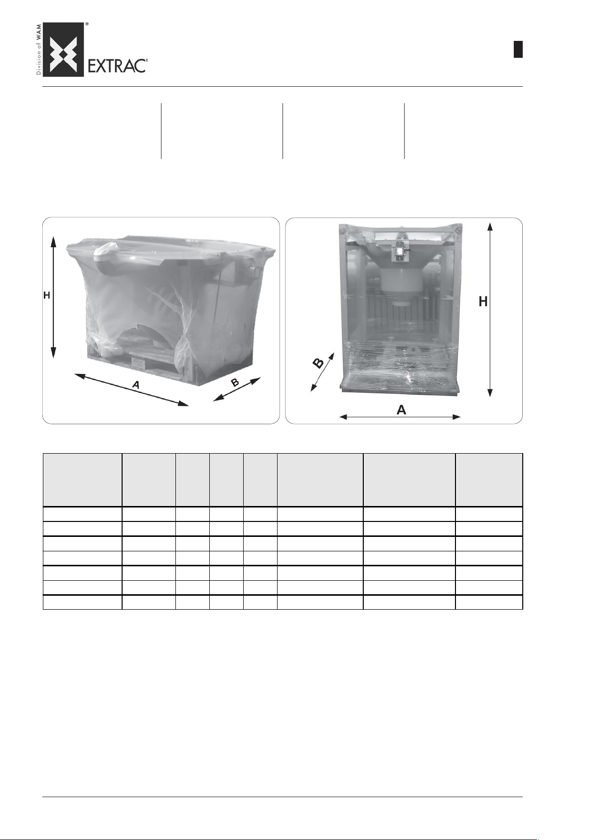
SBB
-
PACKING AND WEIGHTS
-
VERPACKUNGEN UND GEWICHTE
-
EMBALLAGES ET POIDS
-
IMBALLI E PESI
09.07
WA.14 M.
2
11
The FIBC is basically supplied on
a pallet of suitable dimensions,
protected with a heat-shrink polythene cover.
SBB HOPPER PACKING (MODEL T)
VERPACKUNG TRICHTER SBB (MODELL T)
EMBALLAGE TRÉMIE SBB (MODELE T)
IMBALLO TRAMOGGIA SBB (MODELLO T)
In ihrer Standardversion wird die
Big-Bag-Entleerstation auf einer
Palette entsprechender Größe
stehend ausgeliefert und ist durch
eine Schrumpffolie aus Polyäthylen geschützt.
Le vide BIG-BAG est livré en
standard sur une palette de dimensions appropriées et enveloppée dans un film en polyéthylène thermo-rétractable.
SBB PACKING (MODEL C, S, M)
VERPACKUNG SBB (MODELL C, S, M)
EMBALLAGE SBB (MODELE C, S, M)
IMBALLO SBB (MODELLO C, S, M)
Di base lo svuota BIG-BAG viene
fornito su un oallet di dimensioni
opportune e protetto da un involucro di polietilene termoretraibile.
Packing code
Code Verpackung
Code emballage
Co dice imb a llo
IME.SBB.125.T SBB.x.125.T 1600 1400 1000 125 25 150
IME.SBB.150.T SBB.x.150.T 1900 1750 1100 214 30 244
IME.SBB.125.C SBB.x.125.C 1600 1450 2050 321 25 346
IME.SBB.150.C SBB.x.150.C 2050 1950 2200 498 30 528
IME.SBB.125.S SBB.x.125.S 1600 1600 2450 400 25 425
IME.SBB.150.S SBB.x.150.S 2050 2 100 2650 703 30 733
IME.SBB.125.M SBB.x.125.M 2000 2000 2650 750 25 775
TYPE A B H
Equipment weight
Gerätegewicht
Poidsmachine
P es o m acchina
kg
Packing weight
Verpackungsgewicht
Poids e t e mballage
Pes o imba llo
kg
Pes o totale
Pes o totale
Pes o totale
Pes o totale
kg
Page 60

SBB
-
STORING THE MACHINE
-
LAGERHAL TUNG DER MASCHINE
-
EMMAGASINAGE DE LA MACHINE
-
IMMAGAZZINAGGIO DELLA MACCHINA
09.07
WA.14 M.
2
12
1 - STORAGE PRIOR TO IN-
STALLATION
- Avoid damp, salty environments, if possible.
- Place the equipment on wooden platforms and store them
protected from unfavourable
weather conditions.
2 - PROLONGED MACHINE
SHUTDOWNS AFTER ASSEMBLY
- Before starting up the machine,
set it in safety status.
- Prior to commissioning the
machine check the vibrator
motor and all other machine
components are intact and
functioning.
- Allow the pneumatic actuators
to run load-free for at least 10
minutes without any material inside to ensure that all components work correctly.
- Check to ensure correct working
of the electric vibrator, running it
only for a few seconds with the
hopper empty.
1) EINLAGERUNG VOR DEM
EINBAU
- Feuchte und salzhaltige Luft
für die Einlagerung vermeiden.
- Die Einrichtung auf Holzpaletten setzen und vor Witterung
schützen.
2) LÄNGERE BETRIEBSUN-TERBRECHUNGEN NACH DEM EINBAU
- Vor der Inbetriebnahme ist das
Gerät in einen sicheren Zustand zu versetzen.
- Vor der Inbetriebnahme des
Gerätes den elektrischen Unwuchtmotor und alle anderen
Geräteteile auf Unversehrtheit
prüfen sowie auf deren Funktionstüchtigkeit die nach einem
längeren Geräte-stillstand in
Frage gestellt sein könnte.
- Vor dem Einschalten des Gerätes eine Reinigung durchführen.
- Die pneumatischen Austraghilfen wenigstens 10 Minuten
lang ohne Materialfüllung bei
leerem Gerät laufen lassen, um
den korrekten Betrieb aller Komponenten zu sicherzustellen.
- Den Unwuchtmotor auf korrekten Betrieb prüfen, indem man
ihn nur ein paar Sekunden bei
leerem Trichter laufen lässt.
1-EMMAGASINAGE AV ANT LA
MISE EN PLACE
- Si possible éviter les locaux humides et les saumâtres
- Placer l’équipement sur des palettes en bois et les ranger à
l’abri des intempéries.
2-ARRÊT MACHINE PROLON-
GÉ APRÈS LE MONT AGE
- Avant la mise en service, mettre la machine en sécurité.
- Avant la mise en service de la
machine, contrôler l’intégrité du
motovibrateur électrique et de
toutes les parties pour lesquelles un arrêt prolongé pourrait
compromettre le fonctionnement.
- Effectuer un cycle complet de
nettoyage avant de mettre la
machine en marche.
- Laisser fonctionner à vide les
actionneurs pneumatiques
pendant 10 minutes sans
matière à l’intérieur pour vérifier le fonctionnement correct
de chaque composant.
- Vérifier le bon fonctionnement
du moto-vibrateur en le faisant
fonctionner seulement quel-
ques secondes avec la trémie vide.
1-IMMAGAZZINAGGIO PRIMA
DELL’INSTALLAZIONE
- Evitare possibilmente ambienti
umidi e salmastri
- Sistemare l’attrezzatura su pedane di legno e locarle al riparo
dalle intemperie.
2-FERMO MACCHINA PROLUN-
GAT O DOPO IL MONT AGGIO
- Prima della messa in servizio
mettere in sicurezza la macchina.
- Prima della messa in servizio
della macchina controllare l’integrità del motovibratore elettrico e di tutte le parti per le quali
un prolungato arresto potrebbe
compromettere la funzionalità.
- Eseguire un ciclo di pulizia completa prima di attivare la macchina.
- Lasciare funzionare a vuoto gli
attuatori pneumatici per alme-
no 10 minuti senza materiale
all’interno per verificare il corretto funzionamento di ogni componente.
- Verificare il corretto funzionamento del motovibratore facendolo funzionare solo per pochi
secondi con tramoggia vuota.
N.B.: prolonged use of the vibra-
tor with the machine devoid of
product can damage the machine.
3 - POSSIBLE REUSE AFTER
PERIODS OF INACTIVITY
- During machine halts, avoid
damp, salty environments
- Place the equipment on wooden platforms and store them
protected from unfavourable
weather conditions.
- Set the machine in safety status before starting it up.
- Before starting up the machine, check the condition of the
electric vibrator and all parts
for which long shutdowns may
affect working.
- Clean the machine thoroughly
before starting it.
N.B.: Eine längerer Betrieb des
Unwuchtmotors bei leerem
Gerät könnte dieses beschädigen.
3) MÖGLICHE WIEDERVERWENDUNG NACH EINEM LÄNGEREN STILLSTAND
- Während des Stillstands des
Gerätes Räume mit feuchter
und salzhaltiger Luft vermeiden.
- Das Gerät auf Holzpaletten
setzen und vor Witterung
schützen.
- Vor der Inbetriebnahme ist das
Gerät in einen sicheren Zustand zu versetzen.
- Vor der Inbetriebnahme des
Gerätes den elektrischen Unwuchtmotor und alle Teile auf
Unversehrtheit prüfen, deren
Funktionstüchtigkeit durch die
längere Betriebs-unterbrechung in Frage gestellt sein
könnte.
- Vor dem Einschalten des Gerätes eine Reinigung durchführen.
N.B.: l’utilisation prolongée du vi-
brateur avec la machine sans
produit pourrait provoquer des
dommages à la machine.
3-RÉ-UTILISATION APRES UNE
PÉRIODE D’INACTIVITÉ
- Pendant la période d’inactivté
de la machine éviter les locaux
humides et saumâtres
- Placer l’équipement sur des palettes en bois et les ranger à
l’abri des intempéries.
- Prima della messa in servizio
- Avant la mise en service, mettre la machine en sécurité.
- Avant la mise en service de la
machine, contrôler l’intégrité du
motovibrateur électrique et de
toutes les parties pour lesquelles un arrêt prolongé pourrait
compromettre le fonctionnement.
- Effectuer un cycle complet de
nettoyage avant de mettre la
machine en marche.
N.B.: un utilizzo prolungato del
vibratore con macchina scarica
di prodotto potrebbe arrecare
danni alla macchina.
3-POSSIBILE REIMPIEGO
DOPO PERIODO DI INA TTIVITÀ
- Durante il fermo macchina evitare ambienti umidi e salmastri
- Sistemare l’attrezzatura su pedane di legno e locarle al riparo
dalle intemperie.
- Prima della messa in servizio
mettere in sicurezza la macchina.
- Prima della messa in servizio
della macchina controllare l’integrità del motovibratore elettrico e di tutte le parti per le quali
un prolungato arresto potrebbe
compromettere la funzionalità.
- Eseguire un ciclo di pulizia completa prima di attivare la macchina.
Page 61
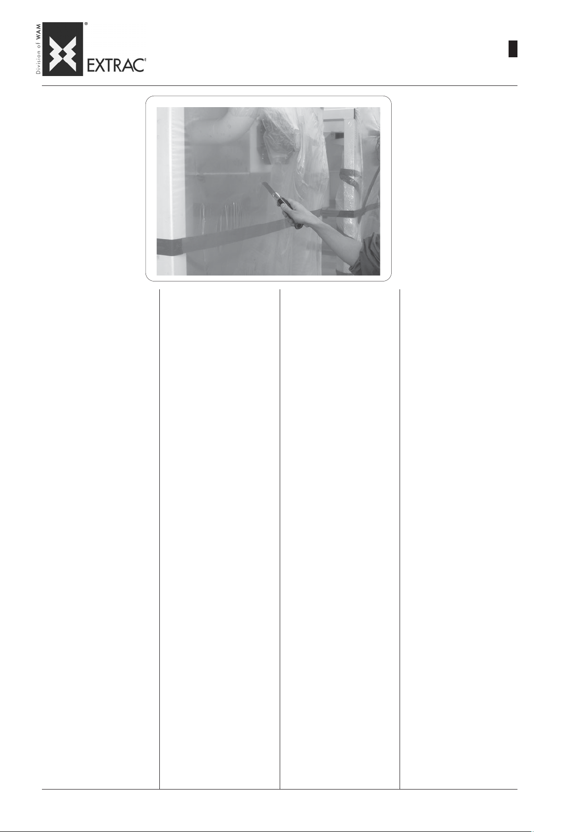
SBB
-
PACKING - UNPACKING
-
VERPACKUNG - AUSP ACKEN
-
EMBALLAGE - DEBALLAGE
-
IMBALLO - RIMOZIONE
09.07
WA.14 M.
2
13
To remove the packing, use a
cutter or a pair of scissors to
cut the heat-shrink nylon covering.
Take special care to avoid damaging parts of the machine and/
or scratch the paint with the
blade.
The FIBCs require certain operations for completing assembly
before starting operation, in particular:
- MODEL T must be fixed to a
solid structure (constructed by
the plant designer).
- MODEL S the removable elements must be mounted in their
seats.
- MODEL M the extensions of
the frame base, their fixing
brackets, the supporting scaffolding for the monorail and the
monorail itself must be mounted.
- All the machines must be fixed
to the ground or to a solid
structure before use.
- Make the electrical connections
of the electric vibrator to all the
machines.
- For all the assembly operations
listed above, proceed as described below.
Zum Entfernen der Verpackung
reicht es aus, einen Cutter oder
eine Schere zu benutzen, mit der
man die Nylon-Schrumpffolie
aufschneidet.
Besonders darauf achten, dass
das Messer keine Teile der Maschine beschädigt und/oder den
Lack aufkratzt.
Die BIG-BAG Entleerstationen
verlangen noch, dass der Zusammenbau beendet wird, bevor man sie in Betrieb nehmen
kann, insbesondere:
- MODELL T: Dieses muss an
einer festen Struktur befestigt
werden (Anfertigung durch
den Anlagenbauer).
- MODELL S: Bei diesem sind
die ausziehbaren Teile innerhalb der eigenen Aufnahme zu
montieren.
- MODELL M: Die Verlängerungsteile des Standardgestells, die Befestigungsbügel
derselben, das Traggerüst für
die Einschienenbahn und die
Einschienenbahn selbst müssen montiert werden. (siehe
unten)
- Alle Maschinen müssen vor
dem Gebrauch am Boden oder
einer soliden Struktur verankert
werden.
- Auf allen Maschinen ist der elektrische Anschluss des Unwuchtmotors vorzunehmen.
- Für die oben genannten Montagevorgänge ist so vorzuge
Pour le déballage il suffit d’utiliser un cutter ou des ciseaux et
de couper le film en nylon thermo-rétractable.
Prêter une attention particulière
à ne pas endommager des parties de la machine et/ou rayer le
vernis avec la lame.
Les vide BIG-BAG nécessitent
quelques opérations pour terminer l’assemblage avant la mise
en marche, à savoir:
- le MODELE T devra être fixé à
une structure solide (réalisée
par l’installateur).
- pour le MODELE S il faudra
monter les éléments amovibles
à l’intérieur de leur emplacement.
- pour le MODELE M il faudra
monter les rallonges de la base
du châssis, leurs supports de
fixation, l’échafaudage de soutien du monorail et le monorail.
(voir ci-après)
- Toutes les machines seront
ancrées par terre ou fixées à
une structure solide avant l’utilisation.
- Sur toutes les machines il faudra réaliser le raccordement
électrique du motovibrateur.
- Pour toutes les opérations de
montage décrites ci-dessus,
suivre les instructions des pages suivantes.
Per la rimozione dell’imballo è
sufficiente utilizzare un cutter o
un paio di forbici per tagliare l’involucro in naylon termoretraibile.
Prestare particolare attenzione
a non danneggiare con la lama
parti della macchina e/o scalfire
la vernice.
Gli svuota BIG-BAG necessitano di alcune operazioni per concluderne l’assemblaggio prima
della messa in funzione, in particolare:
- MODELLO T dovrà essere fissato ad una struttura solida
(fabbricazione a cura dell’impiantista).
- MODELLO S dovranno essere montati gli sfilabili all’interno
della propria sede.
- MODELLO M dovranno essere montati i prolungamenti della
base del telaio, le staffe di fissaggio degli stessi, l’impalcatura di sostegno per la monorotaia e la monorotaia stessa.
(vedi oltre)
- Tutte le macchine dovranno essere ancorate a terra o ad una
struttura solida prima dell’utilizzo.
- Su tutte le macchine andrà effettuato il collegamento elettrico del motovibratore.
- Per tutte le operazioni di montaggio sopraelencate, procedere come descritto in seguito.
NOTE:
It is the installer’s responsibility
to dispose off the packaging in a
suitable manner, in compliance
with existing legislation.
N.B.:
Der Anlagenaufsteller ist dafür
verantwortlich, das Verpackungsmaterial auf angemessene Art und in Übereinstimmung
mit den einschlägigen, geltenden
Gesetzen zu entsorgen.
hen, wie unten beschrieben ist.
N.B.:
L’installateur doit, à ses frais, éliminer les emballages de manière
adéquate et conformément aux
lois en vigueur en la matière.
N.B.:
è a cura dell’installatore smaltire
gli imballi in modo adeguato e
secondo le leggi vigenti in materia.
Page 62
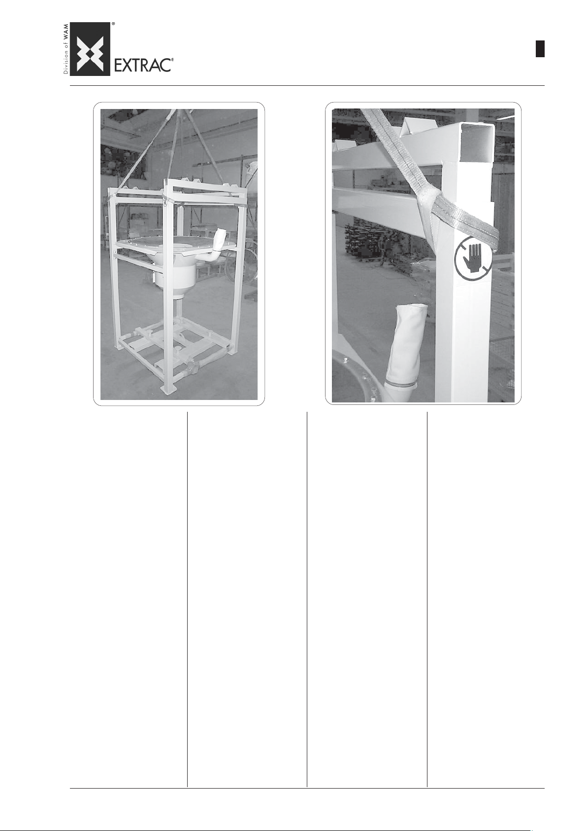
SBB
-
HANDLING
-
HANDLING
-
MANUTENTION
-
MOVIMENTAZIONE
09.07
WA.14 M.
2
14
Use lifting equipment that is suitable for the weight, dimensions
and movements required.
Hook the equipment to the lifting
device by means of flexible
straps and use hooks with safety fasteners.
Do not use clamps, rings, open
hooks or other systems which
do not guarantee the same safety as shackles or hooks with
safety fasteners.
If the straps are in close contact
with the equipment it is advisable to place protective elements
between the two to avoid damage.
CAUTION !
1- Use lifting equipment
which acts from above.
2- Keep the equipment at a
minimum distance above
the ground.
3- Do not stand near or walk
under suspended loads.
Zum Heben Vorrichtungen verwenden, die dem Gewicht der
zu hebenden Last, deren Abmessungen und dem Transport
entsprechen.
Die Befestigung an den Lastaufnahmestellen mittels elastischer Gurte vornehmen und Haken mit Sicherheitsverschluß
verwenden.
Es ist verboten, Klammern, Ringe, offene Haken oder andere
Systeme zu verwenden, die nicht
den Sicher-heitsnormen entsprechen.
Sollten die Anschlaggurte die
Maschine berühren, Schutzelemente dazwischen schieben,
um die Ausrüstung nicht zu beschädigen.
ACHTUNG !
1- Nur Hebezeug verwen-
den, das von oben her angreift.
2- Die Ausrüstung nur so
wenig wie gerade erforderlich heben.
3- Nicht unter der hängen-
den Last gehen oder stehen.
Utiliser des systèmes de levage
appropriés aux poids, dimensions et déplacements prévus.
Effectuer l’accrochage aux prises de levage à l’aide de sangles élastiques et utiliser des
crochets avec fermeture de sécurité.
L’utilisation de mors, anneaux,
crochets ouverts ou tout système ne garantissant pas la même
sécurité que les manilles ou les
crochets à fermeture de sécurité est interdite.
En cas de contact entre les sangles et les pièces de l’équipement, il est conseillé d’intercaler
des protections pour ne pas endommager ce dernier.
ATTENTION !
1- Utiliser des appareils de
levage agissant par le
haut.
2- Tenir la machine à une
distance minimum du
sol.
3- Ne pas stationner sous
les charges suspendues.
Utilizzare sistemi di sollevamento idonei alle masse, alle dimensioni e agli spostamenti previsti.
Eseguire l’ aggancio alle prese
di sollevamento mediante fasce
elastiche e utilizzare ganci con
chiusure di sicurezza.
E’ vietato l’ utilizzo di morsetti,
anelli, ganci aperti o qualsiasi sistema che non garantisca la
stessa sicurezza dei grilli o dei
ganci con chiusura di sicurezza.
Nel caso si verificassero contatti tra le fasce e parti della macchina, è consigliabile frapporre
degli elementi di protezione per
evitare danni a quest’ ultima.
ATTENZIONE !
1- Utilizzare apparecchi di
sollevamento che agiscono dall’ alto.
2- Tenere la macchina alla
minima distanza da terra.
3- Non sostare o passare
sotto i carichi sospesi.
Page 63
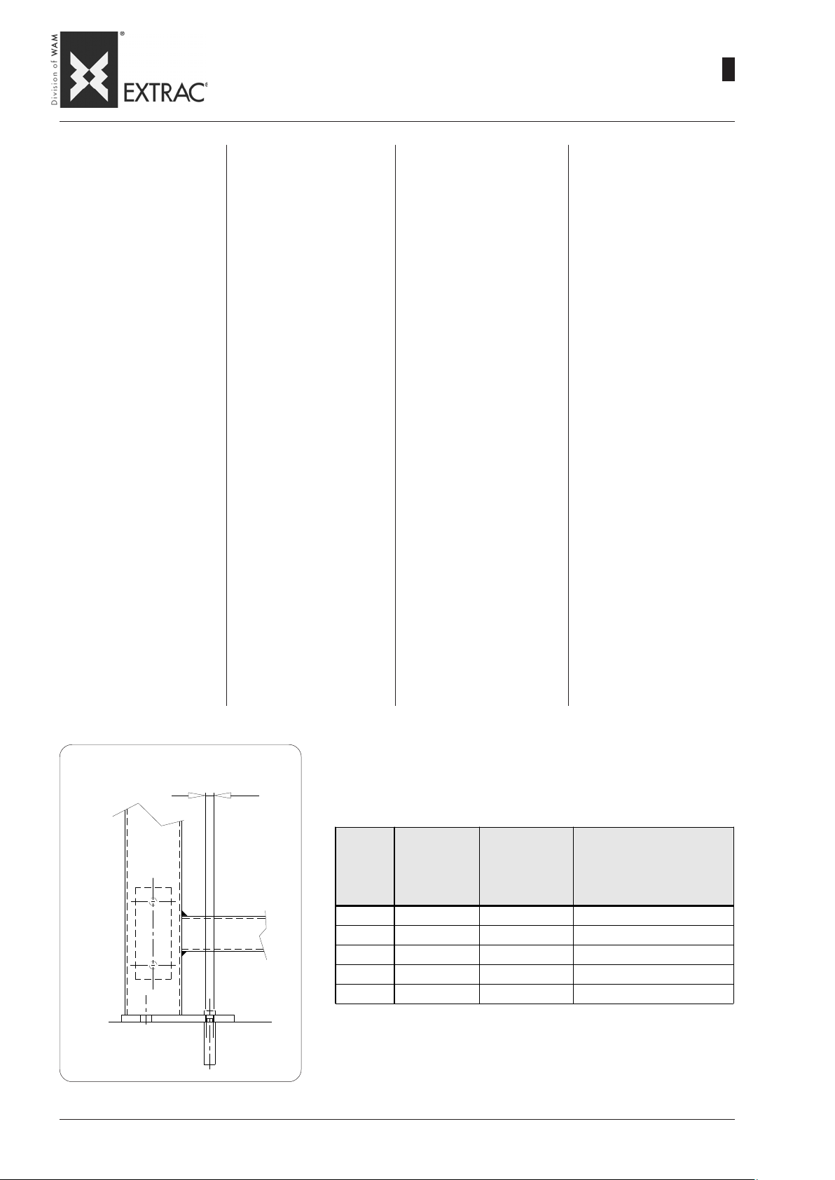
SBB
-
INSTALLATION - ANCHORING
-
INSTALLA TION - BEFESTIGUNG
-
INSTALLA TION - NORMES DE FIXATION
-
INSTALLAZIONE - NORME DI FISSAGGIO
09.07
WA.14 M.
2
15
While defining the installation of
the equipment, take into account
the space required for maintenance and access, for loading
the FIBCs, especially as regards
height, as it is variable.
This space depends on the lifting and handling equipment
available at the work site.
The place in which the equipment is located must have the
necessary connections (electricity, air, etc.) for operating the
equipment.
It is the Customer's responsibility to equip the assembly area in
accordance with the existing
regulations and safety requirements: aeration, earthing, etc.
Assembly instructions:
- Lift and position the equipment
(according to the procedure
indicated on the previous
page) near the supply lines.
- Countermark the position of the
four anchor holes on the ground
corresponding to the frame
supporting plate.
- Move the frame, make the bores
as shown in the T able and reposition the equipment.
- Check that the equipment is longitudinally and transversely
perfectly level.
- Fit the plugs into the bores and
tighten them.
Bei der Festlegung des Standortes der Ausrüstung auch den
für die Wartung und den Zugriff
erforderlichen Platz berücksichtigen, der für die Aufgabe des
Big-Bags dient, vor allem deshalb, weil die Höhe variabel ist.
Dieser Platz hängt vom Förderund Hebezeug ab, das auf der
Baustelle vorhanden ist.
Der Standort muß mit den erforderlichen Anschlüssen (Strom,
Luft etc.) versehen sein, damit
die Ausrüstung in Betrieb genommen werden kann.
Für die Einrichtung des Montageraums und die Beachtung
der geltenden Normen und die
Sicherheitserfordernisse (Belüftung, Erdung etc. ist der Anwender verantwortlich.
Montageanweisungen:
- Das Gerät auf der Höhe der
Versorgungsleitung aufstellen
(Vorgehensweise siehe vorangegangene Seite).
- Die Befestigungsbohrungen,
die sich auf der Platte der Stellfläche des Rahmens befinden,
am Boden markieren.
- Das Gestell seitlich ablegen,
Bohrungen lt. Tabelle vorsehen und das Gerät wieder aufstellen.
- Sicherstellen, daß das komplette Gerät in der Waage steht,
sowohl in der Längs- als auch
in der Querrichtung.
- Die Dübel in die Bohrungen einführen und anziehen.
Lors de la détermination de l’emplacement de l’équipe-ment tenir
compte des espaces d’entretien
et d’accès, pour le chargement
du sac, surtout en hauteur car
celle-ci est variable.
Cet espace dépend des moyens
de levage et de manutention disponibles au chantier.
Le local devra être doté des raccordements nécessaires (énergie électrique, air, etc.) pour le
fonctionnement de l’équipement.
Le client a la responsabilité
d’équiper le lieu de montage dans
le respect des normes en vigueur
sur la sécurité: aération, mise à
la terre, etc.
Instructions de montage:
- Soulever et mettre en place (suivant les procédures indiquées
dans la page précédente) au
niveau de la ligne d’alimentation.
- Faire sur le sol les marques des
trous de fixation situés sur les
plaques d’ancrage du bâti.
- Déplacer le bâti, exécuter les
trous comme indiqué dans le
tableau et positionner de nouveau l’équipement.
- Contrôler que l’équipement est
parfaitement horizontal dans le
sens longitudinal et transversal.
- Insérer les bouchons dans les
trous et visser.
Nel definire la dislocazione della
macchina tenere conto degli spazi di manutenzione e di accesso,
per il carico del saccone, soprattutto in altezza in quanto questa
è variabile.
Suddetto spazio dipende dai
mezzi di sollevamento e movimentazione disponibili in cantiere.
Il locale dovrà essere dotato degli allacciamenti necessari (energia elettrica, aria, ecc...) per il
funzionamento della macchina.
E’ responsabilità del cliente attrezzare il luogo di montaggio rispettando le normative vigenti e
i requisiti di sicurezza: aereazione, messa a terra, ecc...
Istruzioni per il montaggio:
- Sollevarlo e posizionarlo (secondo le procedure indicate
nella pagina precedente) in
corrispondenza della linea di
alimentazione.
- Contromarcare sul pavimento i
fori di fissaggio situati sulle piastre d’ appoggio del telaio.
- Spostare il telaio, eseguire i fori
come indicato nella tabella e riposizionare la macchina.
- Controllare che la macchina sia
perfettamente orizzontale in
senso longitudinale e trasversale.
- Inserire i tappi nei fori e avvitare.
PLATE BORE- BOHRUNG PLA TTE
TROU PLAQUE - FORO PIASTRA
Earth wire - Erdungskabel
Fil de terre - Filo terra
Ø
Ø
CODE
SBB125C
SBB125S
SBB150C
SBB150S
SBB125M
PLATE HOLE
LOCH PLATTE
TROU PLAQUE
FORO PIASTRA
mm
16.5 12 /
16.5 12 /
22 16 /
22 16 /
22 8 1250 daN
NBR OF HOLES
LOCHZAHL
NBRE DE TROUS
N° FORI
MAX. PULL FOR FIXING
MAX. ZUG PRO SCHRA UBE
TRACTION MAXI POUR ANCRAGE
TIRO MAX. PER ZANCA
Page 64
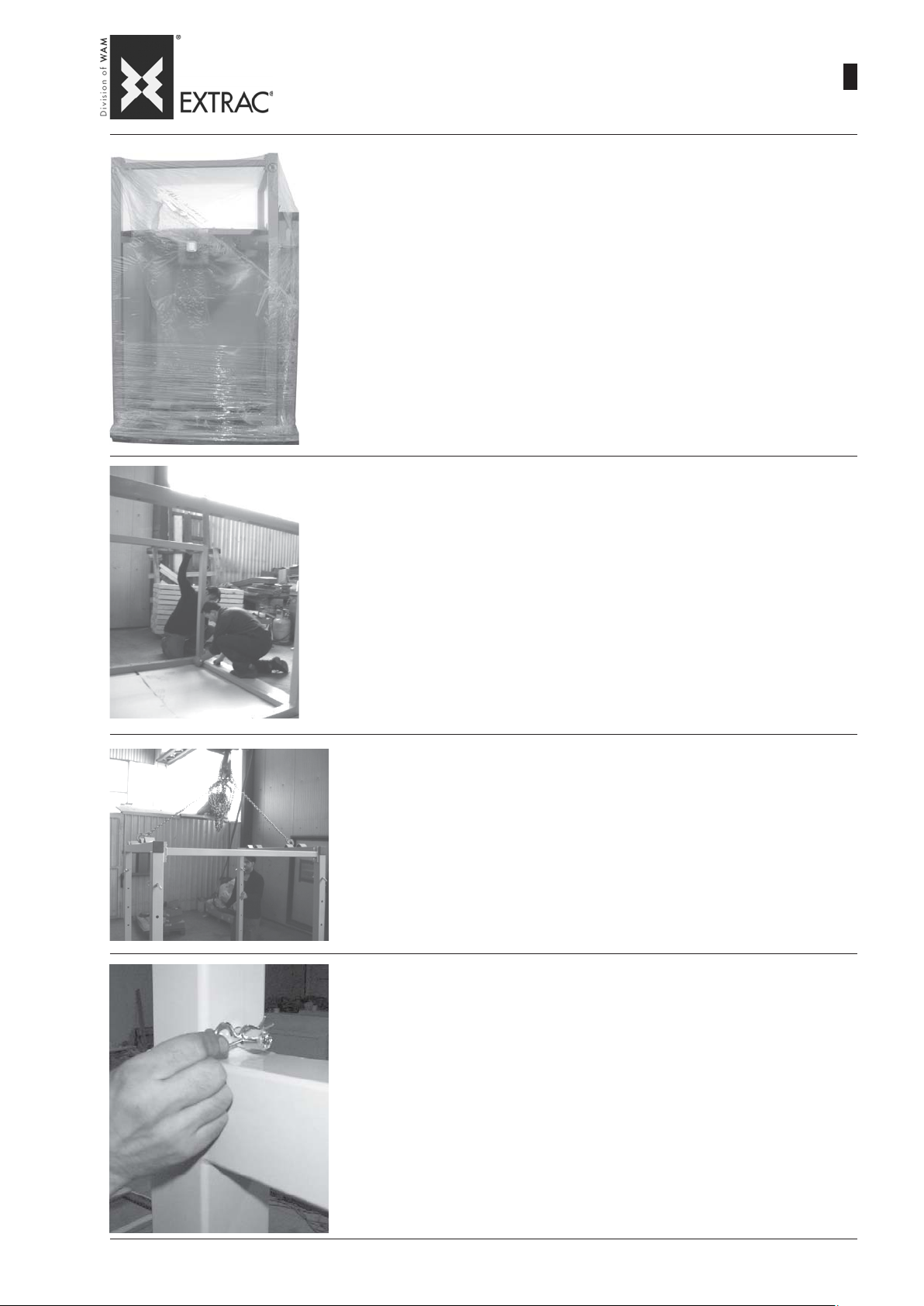
SBB
-
INSTALLATION - ASSEMBLY OF MODEL S
-
INSTALLATION - ZUSAMMENBAU MODELL S
-
INST ALLATION - ASSEMBLAGE MODELE S
-
INST ALLAZIONE - ASSEMBLAGGIO MODELLO S
1) The MODEL S FIBC is supplied with the removable frame dismantled. Once the
covering is removed, complete the assembly as follows:
1) Die BIG-BAG Entleerstation MODELL S wird mit dem herausziehbaren Rahmen
im zerlegten Zustand geliefert. Nach dem Entfernen der Verpackung wie folgt
vorgehen, um die Montage zu beenden:
1) Le vide BIG-BAG MODELE S est livré avec le châssis amovible démonté. Après
avoir enlevé le film de l’emballage, pour terminer le montage procéder de la manière
suivante :
1) Lo svuota BIG-BAG MODELLO S viene fornito con il telaio sfilabile smontato.
Una volta rimosso l’involucro dell’imballo, per ultimare il montaggio procedere
come segue:
09.07
WA.14 M.
2
16
2) Connect the removable legs by means of the cross-beam and tighten the screws
2) Die herausziehbaren Beine mit der Querstrebe verbinden und die Schrauben gut
anziehen.
2) Relier les pieds amovibles au moyen de la traverse prévue à cet effet et bien serrer
les vis
2) Collegare le gambe sfilabili mediante apposita traversa e serrare bene le viti
4) Lift the removable frame take care to avoid damaging it and insert it into the fixed
frame
4) Das ausziehbare Gestell heben, wobei darauf zu achten ist, dass man es nicht
beschädigt, um es dann in das Innere des festen Gestells zu stecken.
4) Soulever le châssis amovible en faisant attention à ne pas l’endommager et l’introduire dans le châssis fixe.
4) Sollevare il telaio sfilabile facendo attenzione a non danneggiarlo ed infilarlo
all’interno del telaio fisso.
3) Position the stop pins according to the BIG-BAG dimensions and re-hook the cotter
pins.
3) Die Befestigungsstifte je nach der Größe der BIG-BAG anordnen und die Sicherungssplinte wieder einrasten lassen.
3) Positionner les axes d’arrêt en fonction des dimensions du BIG-BAG et ensuite
raccrocher les goupilles de sécurité.
3) Posizionare le spine di fermo in funzione delle dimensioni del BIG-BAG e riaggan-
ciare le copiglie di sicurezza.
Page 65
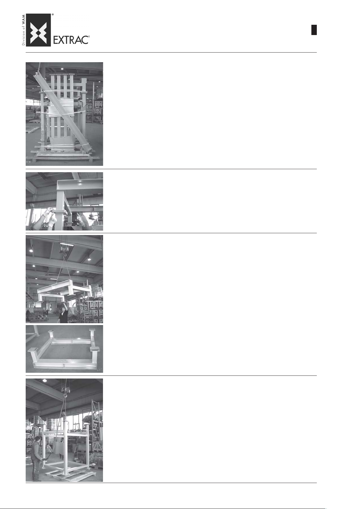
SBB
-
INSTALLATION - ASSEMBLY OF MODEL M
-
INSTALLATION - ZUSAMMENBAU MODELL M
-
INSTALLATION - ASSEMBLAGE MODELE M
-
INSTALLAZIONE - ASSEMBLAGGIO MODELLO M
1) The MODEL M BIG-BAG unloader is supplied partially dismantled to optimize transport.
About two hours are required to complete assembly at the site; after unpacking and
placing all the objects on the floor, proceed as follows:
1) Die BIG-BAG Entleerstation MODELL M wird teilweise zerlegt ausgeliefert, um den
Transport zu optimieren. Um den Zusammenbau vor Ort zu vervollständigen, sind
circa 2 Arbeitsstunden anzuschlagen. Nach dem Erntfernen der Verpackung und dem
Anlegen aller Teile am Boden wie folgt vorgehen:
1) Le vide BIG-BAG MODELE M est fourni partiellement démonté pour optimiser le transport.
Il faut environ 2 heures de travail pour réaliser l’assemblage sur place; après avoir
enlevé le film d’emballage, procéder de la manière suivante :
1) Lo svuota BIG-BAG MODELLO M viene fornito parzialmente smontato per ottimizzarne il trasporto. Sono necessarie all’incirca 2 ore di lavoro per ultimarne l’assemblaggio in loco; una volta rimosso l’involucro dell’imballo e depositati tutti gli oggetti a
terra, procedere come segue:
2) Slacken the screws connecting the hoist frame 1 to hopper frame 2.
WA.14 M.
09.07
2
17
2) Die Schrauben losdrehen, die den Flaschenzugrahmen 1 mit dem Trichtergestell 2
verbinden.
2) Dévisser les vis qui relient le châssis palan 1 et le châssis de la trémie 2.
2) Svitare le viti che collegano il telaio paranco 1 dal telaio tramoggia 2.
3) Using a suitable lifting system, lift the hoist frame and put it aside upside down
3) Das Flaschenzuggestell mit einem geeigneten Gerät heben und separat auf dem Kopf
abstellen.
3) Soulever le châssis palan à l’aide d’un système de levage approprié et le mettre de côté,
renversé.
3) Sollevare mediante apposito sistema di sollevamento il telaio paranco e deporlo in
disparte rovesciato
4) Lift the hopper frame and place it in the final position, fixing the feet to the ground
4) Das Trichtergestell heben und in der endgültigen Position abstellen, um dann die Füße
am Boden zu befestigen.
4) Soulever le châssis de la trémie et le mettre dans sa position définitive, en fixant les pieds
par terre
4) Sollevare il telaio della tramoggia e disporlo in posizione definitiva fissandone i piedi
a terra
Page 66
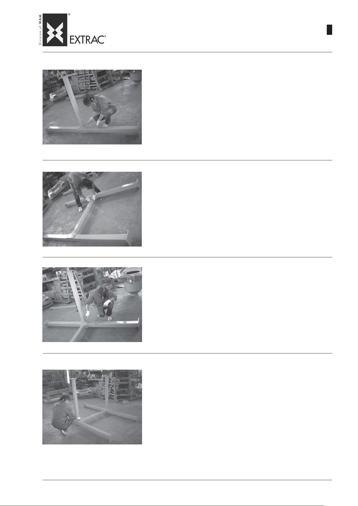
SBB
-
INSTALLATION - ASSEMBLY OF MODEL M
-
INSTALLATION - ZUSAMMENBAU MODELL M
-
INSTALLATION - ASSEMBLAGE MODELE M
-
INSTALLAZIONE - ASSEMBLAGGIO MODELLO M
5) Place a rear strut 4 on the ground as shown in the Figure and connect a cross beam
5 to it by means of screws, taking care to avoid tightening the screws excessively
5) Einen hinteren Mast 4 auf den Boden legen, wie im Bild zu sehen ist, und eine
Querstrebe 5 anschrauben, wobei zu beachten ist, dass die Schrauben nicht zu
fest angezogen werden.
5) Placer un pylône 4 arrière par terre, comme montré sur la figure et visser une
traverse 5 sans serrer excessivement les vis
5) Disporre un pilone 4 posteriore al suolo come mostrato in figura e avvitare una
traversa 5 avendo cura di non serrare eccessivamente le viti
6) Place the frame down and connect the second rear strut taking care to orient it as
shown in the Figure.
6) Die Struktur hinlegen und den zweiten hinteren Mast befestigen, wobei darauf zu
achten ist, dass er wie im Bild gezeigt ausgerichtet wird.
09.07
WA.14 M.
2
18
6) Allonger la structure et relier le deuxième pylône arrière en le dirigeant comme
indiqué par la figure.
6) Sdraiare la struttura e collegare il secondo pilone posteriore avendo cura di
orientarlo come in figura.
7) Connect a second beam 6 as shown in the Figure, taking care to avoid tightening
the screws excessively
7) Eine zweite Querstrebe 6 anschließen, wie in der Abbildung zu sehen ist, wobei
darauf zu achten ist, dass die Schrauben nicht zu straff angezogen werden.
7) Relier une deuxième traverse 6, comme l’indique la figure, en faisant attention à ne
pas trop serrer les vis
7) Collegare una seconda traversa 6 come mostrato in figura avendo cura di non
serrare eccessivamente le viti
8) Connect the last cross beam as shown in the Figure, taking care to avoid tightening
the screws excessively.
8) Die vormontierte Struktur mit einem Kran oder einen ähnlichen System heben
und den zweiten hinteren Mast befestigen, wobei darauf zu achten ist, dass die
Schrauben nicht zu straff angezogen werden. Nun muss die Struktur ein stabiles
Gleichgewicht aufweisen.
8) Relier la dernière traverse comme l’indique la figure, sans serrer excessivement
les vis.
8) Collegare l’ultima traversa come mostrato in figura, avendo cura di non serrare
eccessivamente le viti.
Page 67

SBB
-
INSTALLATION - ASSEMBLY OF MODEL M
-
INSTALLATION - ZUSAMMENBAU MODELL M
-
INSTALLATION - ASSEMBLAGE MODELE M
-
INSTALLAZIONE - ASSEMBLAGGIO MODELLO M
8) Using a crane or similar system, lift the pre-assembly and fix the third strut taking care to
avoid tightening the screws excessively. The structure will now be stable
8) Die vormontierte Struktur mit einem Kran oder einem ähnlichen System heben und den
dritten Mast befestigen, wobei ebenfalls zu beachten ist, dass man die Schrauben nicht
zu fest anzieht. Nun muss die Struktur ein stabiles Gleichgewicht haben.
8) A l’aide d’une grue ou d’un système similaire soulever la structure pré-assemblée et fixer
le troisième pylône sans serrer excessivement les vis. Après quoi la structure sera en
équilibre stable
8) Sollevare mediante gru o sistema simile il pre-assemblato e fissare il terzo pilone
avendo cura di non serrare eccessivamente le viti. A questo punto la struttura sarà in
equilibrio stabile
10)Complete the chassis fixing the last of the struts as shown in the Figure; again take care
to avoid tightening the screws excessively
09.07
WA.14 M.
2
19
10)Das Gestell fertig montieren, indem man den letzten der Maste befestigt, wie in der
Abbildung zu sehen ist. Erneut darauf achten, die Schrauben nicht zu fest anzuziehen.
10)Compléter le châssis en fixant le dernier pylône comme l’indique la figure ; même dans ce
cas il ne faut pas trop serrer les vis
10)Completare lo chassis fissando l’ultimo dei piloni come mostrato in figura; ancora una
volta non serrare eccessivamente le viti
11) Lift the chassis carefully using a crane or a forklift truck and place it on top of the hoist
frame as shown in the Figure
11) Das Gestell sorgfältig mit einem Kran oder Gabelstapler geben und über dem Flaschenzuggestell abstellen, wie im Bild zu sehen ist.
11) A l’aide d’une grue ou d’un chariot élévateur soulever le châssis et l’appuyer sur le
châssis pour palan comme le montre la figure.
11) Sollevare con cura mediante una gru o carrello elevatore lo chassis ed appoggiarlo
sopra al telaio per paranco come mostrato in figura
12) Fix the hoist frame to the chassis by means of the 16 M16 bolts and tighten these
12) Das Flaschenzuggestell mit 16 Schraubbolzen M16 am Gestell befestigen und diese
Schrauben gut anziehen.
12) Fixer le châssis du palan sur le châssis au moyen des 16 boulons M16 en veillant à bien
les serrer
12) Fissare il telaio paranco allo chassis mediante i 16 bulloni M16 e serrare bene questi
ultimi
Page 68
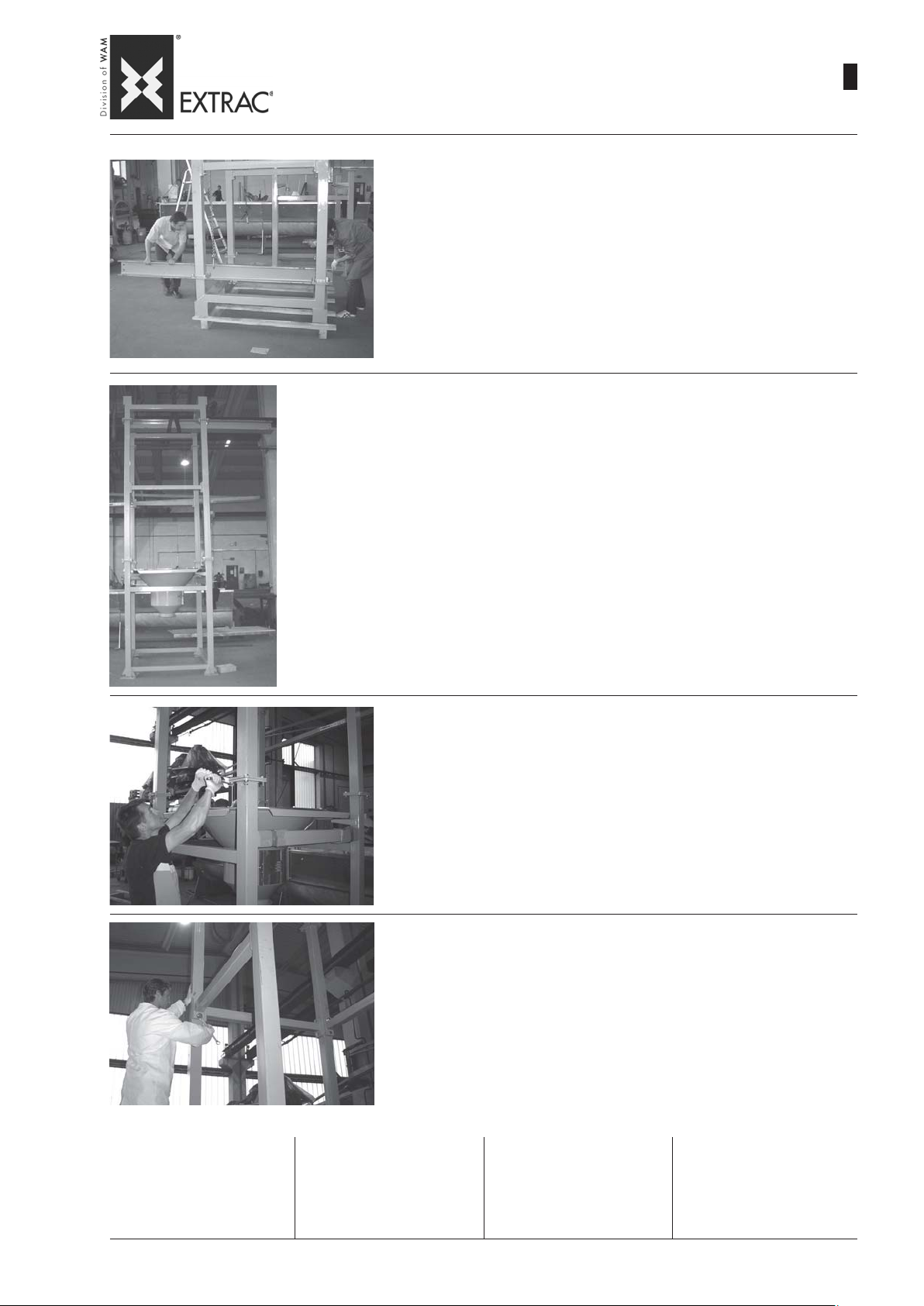
-
INSTALLATION - ASSEMBLY OF MODEL M
-
SBB
INSTALLATION - ZUSAMMENBAU MODELL M
-
INSTALLATION - ASSEMBLAGE MODELE M
-
INSTALLAZIONE - ASSEMBLAGGIO MODELLO M
13) Fix the beam 3 for the hoist on hoist frame using the 8 M20 bolts and tighten the
assembly firmly
13) Den Balken 3 für den Flaschenzug mit den 8 Schraubbolzen M20 am Flaschenzugrahmen befestigen und alles gut anziehen.
13) Fixer la poutre 3 pour le palan sur le châssis du palan au moyen des 8 boulons
M20 et bien serrer le tout
13) Fissare la trave 3 per il paranco sul telaio paranco mediante gli 8 bulloni M20
e serrare bene il tutto
14) Using a suitable crane or forklift truck lift the entire block A and position it on top of the hopper
frame B taking care to align the holes of the connecting flanges
14) Den ganzen Block A mit Kran oder Gabelstapler heben und über dem Trichtergestell B
anordnen, wobei darauf zu achten ist, dass die Löcher der Verbindungsflansche übereinander zu liegen kommen.
WA.14 M.
09.07
2
20
14) A l’aide d’une grue ou d’un chariot élévateur soulever tout l’ensemble A et le poser au-dessus
du châssis trémie B en veillant à faire coïncider les orifices des brides d’accouplement
14) Mediante gru o carrello elevatore adeguato sollevare l’intero blocco A e posizionarlo sopra
il telaio tramoggia B avendo cura di far combaciare i fori delle flangie di collegamento
15) Insert the connecting bolts and tighten them
15) Die Verbindungsschrauben einstecken und gut anziehen.
15) Introduire les boulons d’accouplement et les serrer
15) Inserire i bulloni di collegamento e serrarli bene
16) Now tighten all the bolts of the chassis and carry out a final check on all the bolts
to make sure they are tightened perfectly
16) Nun alle Schraubbolzen des Gestells gut anziehen und die anschließende
Kontrolle ausführen, um sicherzugehen, dass alle Schraubteile fest angezogen
sind.
Important:
use a torque wrench to ensure
the following tightening torques:
M16 screws: 225 Nm
M18 screws: 439 Nm
16) Après quoi bien serrer tous les boulons du châssis et effectuer un contrôle final
du serrage correct de tous les boulons
16) Provvedere ora a serrare bene tutti i bulloni dello chassis ed eseguire un
controllo finale sul corretto serraggio di tutta la bulloneria
Wichtig:
Einen Drehmomentschlüssel benutzen, um die folgenden Anzugsdrehmomente zu erhalten:
Schrauben M16: 225 Nm
Schrauben M18: 439 Nm
Important :
utiliser une clé dynamométrique
afin de garantir les couples de
serrage suivant :
Vis M16 : 225 Nm
Vis M18 : 439 Nm
Importante:
utilizzare una chiave dinanometrica al fine di garantire le seguenti coppie di serraggio:
Viti M16: 225 Nm
Viti M18: 439 Nm
Page 69

SBB
-
ELECTRICAL CONNECTIONS
-
ELEKTRISCHE ANSCHLÜSSE
-
RACCORDEMENTS ÉLECTRIQUES
-
COLLEGAMENTI ELETTRICI
09.07
WA.14 M.
2
21
GENERAL WARNINGS
1.1 All the connections to the
supplies must be carried out according to existing safety regulations.
1.2 Before start-up, check the
efficiency of the earth connection.
1.3 Check the supply voltage and
cycles to ensure these correspond with the values on the
motor rating plate.
1.4 Provide protection against
overload; ensure the calibrated
values of the thermal or magnetothermal current do not exceed
those on the rating plate.
1.5 The electrical connection
must be carried out according to
the following sequence:
- disconnect the mains supply.
- Pass the power cable through
the cable gland into the junction box.
- make the connections using the
accessories provided.
- tighten the cable glands completely.
- fit the junction box cover taking
care to avoid damaging the
seal.
ALLGEMEINE WARNHINWEISE
1.1 Alle Anschlüsse an das
Stromnetz müssen gemäß der
geltenden Sicherheitsbestimmungen ausgeführt werden.
1.2 Vor der Inbetriebnahme ist
der Erdungsanschluß auf Funktionstüchtigkeit zu prüfen.
1.3 Sicherstellen, daß Spannung
und Frequenz den Werten auf
dem Typenschild des Motors entsprechen.
1.4 Einen Überlastschutz vorsehen, dabei auch prüfen, ob die
Einstellwerte der Thermorelais
oder Motorschutzschalter nicht
über dem Wert des Typenschilds
liegen.
1.5 Der Stromanschluß ist in folgender Reihenfolge vorzunehmen:
- Die allgemeine Stromversorgung ausschalten.
- Die Speisekabel durch die Kabeldurchführung in das Innere
des Anschlußkastens stecken.
- Die Anschlüsse mit den vorgesehenen Zubehörteilen vornehmen.
- Die Kabeldurchführungen fest
anziehen.
- Den Kastendeckel montieren
und dabei beachten, daß die
Dichtung nicht beschädigt wird.
CONSIGNES GENERALES
1.1 Tous les raccordements au
secteur électrique doivent être
réalisés conformément aux normes de sécurité en vigueur.
1.2 Avant la mise en route vérifier la mise à la terre et son efficacité.
1.3 Contrôler que la tension et la
fréquence d’alimentation correspondent aux valeurs de plaque
du moteur.
1.4 Prévoir des protections contre les surcharges, en vérifiant
que les valeurs du courant de
réglage de l’interrupteur ne dépasse pas ceux de plaque.
1.5 Le raccordement électrique
doit être effectué dans la séquence ci-dessous:
- débrancher l’alimentation électrique générale.
- Passer les câbles d’alimentation à travers les serre-câbles,
à l’intérieur du boîtier de connexion.
- Exécuter les raccordements en
utilisant les accessoires prévus à cet effet.
- Serrer à fond les serre-câbles.
- Monter le couvercle du boîtier
en faisant attention à ne pas
endommager le joint.
AVVERTENZE GENERALI
1.1 Tutti i collegamenti alla rete
di alimentazione devono essere
eseguiti secondo le norme di sicurezza vigenti.
1.2 Prima dell’ avviamento assicurarsi del perfetto collegamento a terra verificandone l’ efficienza.
1.3 Controllare che tensione e
frequenza di alimentazione siano corrispondenti ai valori di targa del motore.
1.4 Prevedere delle protezioni di
sovraccarico, verificando che i
valori della corrente di taratura
del termico o magnetotermico
non superino quelli di targa.
1.5 Il collegamento elettrico dovrà essere eseguito in sequenza:
- disinserire l’ alimentazione elettrica generale.
- inserire i cavi di alimentazione
attraverso i pressacavi, all’ interno della scatola di collegamento.
- eseguire i collegamenti utilizzando gli appositi accessori.
- serrare a fondo i pressacavi.
- montare il coperchio della scatola facendo attenzione a non
danneggiare la guarnizione.
CAUTION !
The cross section of the
power cable and safety cable must be defined by the
buyer. The user must provide a differential automatic
circuit-breaker upline of the
main switch.
PRECAUTION
Connecting the machine to
the mains supply must be
done in accordance with the
existing regulations of the
country where the machine
is being used.
ACHTUNG !
Für die Stromkabel- und Sicherungskabelquer-schnitte ist der Betreiber verantwortlich. Der Betreiber muß
stromauf vom Hauptschalter
der Anlage einen Fehlerstrom-Schutzschalter vorsehen.
VORSICHTMASSNAHME
Der Anschluß der Ausrüstung an das Netz muß unter
Beachtung der Normen ausgeführt werden, die im Land
des Anwenders gelten.
ATTENTION !
Le dimensionnement des
câbles d’ alimentation et du
câble de protection est sous
la responsabilité de l’acheteur. L’ utilisateur doit appliquer en amont de l’interrupteur général de l’installation,
un interrupteur automatique
différentiel.
PRECAUTION
Le raccordement de la machine au secteur doit être
effectué dans le respect de
la réglementation en vigueur
dans le pays de l’utilisateur.
ATTENZIONE !
Il dimensionamento dei cavi
di alimentazione e del cavo
di protezione è responsabilità dell’ acquirente. L’ utilizzatore deve applicare a
monte dell’ interruttore generale dell’ impianto, un interruttore automatico differenziale.
PRECAUZIONE
Nel collegare la macchina
alla rete, rispettare la regolamentazione in vigore nel
paese dell’ utilizzatore.
Page 70
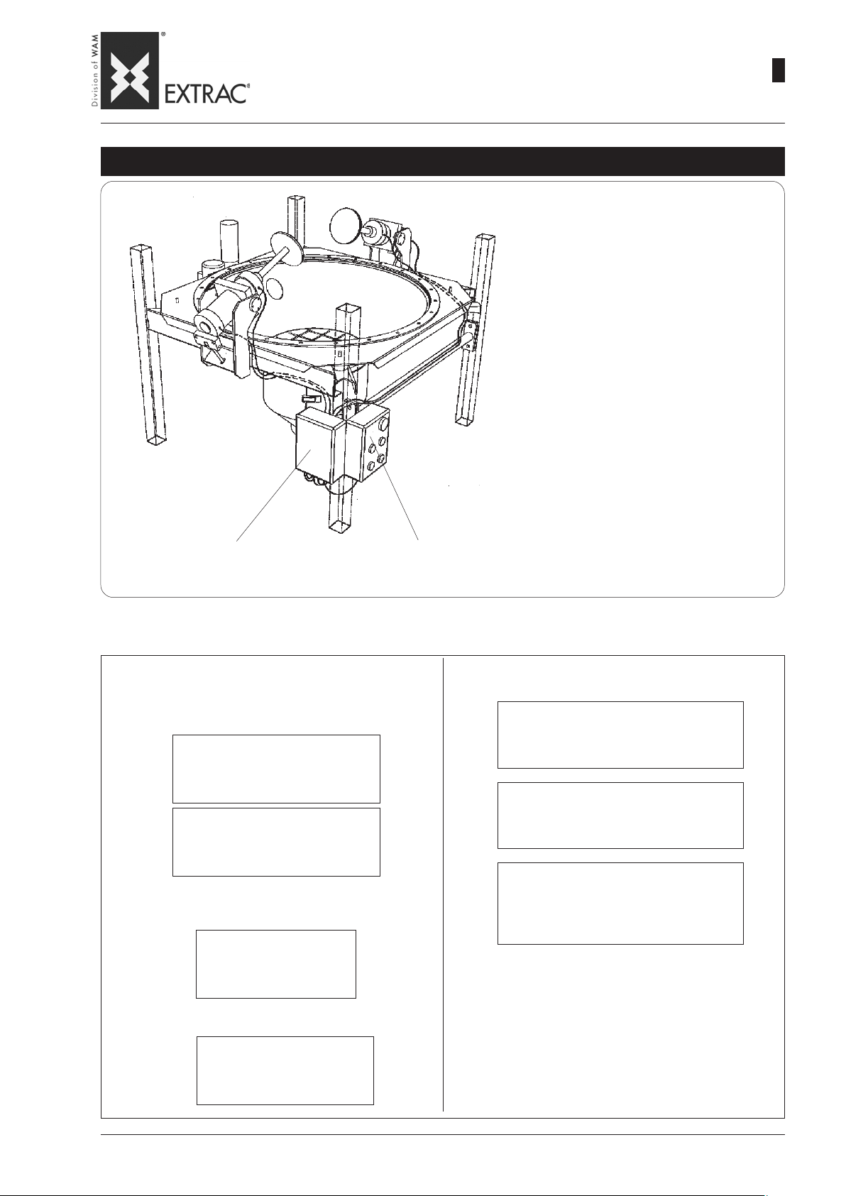
-
ELECTRIC-PNEUMATIC ACTUA TORS CONNECTION
-
SBB
PNEUMATIC ACTUATORS KIT - BAUSATZ PNEUMATISCHE AUSTRAGHILFEN
ELEKTRISCHER UND PNEUMATISCHER ANSCHLUSS DER AUSTRAGHILFEN
-
RACCORDEMENT ÉLECTRIQUE-PNEUMATIQUE DES ACTIONNEURS
-
COLLEGAMENTO ELETTRO - PNEUMATICO ATTIVATORI
KIT ACTIONNEURS PNEUMATIQUES - KIT ATTIVATORI PNEUMATICI
09.07
WA.14 M.
2
22
AIR INLET
LUFTEINLASS
ENTRÉE AIR
ENTRAT A ARIA
PNEUMATIC P ANEL
PNEUMATISCHE STEUERUNG
ARMOIRE PNEUMATIQUE
QUADRO PNEUMATICO
ELECTRICAL DATA - ELEKTRISCHE DATEN
CARACTÉRISTIQUES ÉLECTRIQUES - DA TI ELETTRICI
Mains Voltage - Betriebsspannung
Tension d'alimentation - Tensione di alimentazione
•
AIR OUTLET
•
LUFTAUSLASS
SORTIE AIR
USCITA ARIA
ELECTRIC PANEL
ELEKTROSTEUERUNG
ARMOIRE ÉLECTRIQUE
QUADRO ELETTRICO
Line: Three-phase 380V. + Earth
Leitung: dreiphasig 380V. + Erde
Ligne: Troisphase 380V. + Terre
Linea: Trifase 380V. + Terra
Auxiliaries: 1 10VAC
Steuerspannung: 110V WS
Auxiliaires: 1 10VCA
Ausiliari: 110vca
Fréquence d'alimentation - Frequenza di alimentazione
Mains frequency - Betriebsfrequenz
Cycles:
Frequenz:
Fréquence:
50 Hz
Frequenza:
VERLAUF DER ZYLINDERVERSORGUNGSLEITUNGEN
FIBC LOAD SIDE
AUFGABESEITE BIG-BAG
CÔTÉ CHARGEMENTT BIG-BAG
LATO CARICO BIG-BAG
PNEUMATIC DATA - PNEUMATISCHE DATEN
CARACTÉRISTIQUES PNEUMATIQUES - DATI PNEUMATICI
CYLINDER INFEED PIPING PATH
PARCOURS TUBES ALIMENT A TION CYLINDRES
PERCORSO TUBI ALIMENTAZIONE CILINDRI
Inlet pressure:
Eingangsdruck:
6 bar
Pression d'entrée:
Pressione d'ingresso:
Operating pressure:
Betriebsdruck:
6 bar max
Pression de service:
Pressione d'esercizio:
Air consumption max:
Luftverbrauch max:
Consomm. d'air max:
66.72 Nl/min
Consumo d'aria max:
(AVANTI / INDIETRO)
Consumption - Verbrauch - Consommation - Consumi
Max. Ampere:
Max. Stromaufnahme:
Ampère maxi:
2 A
Amper max:
Page 71
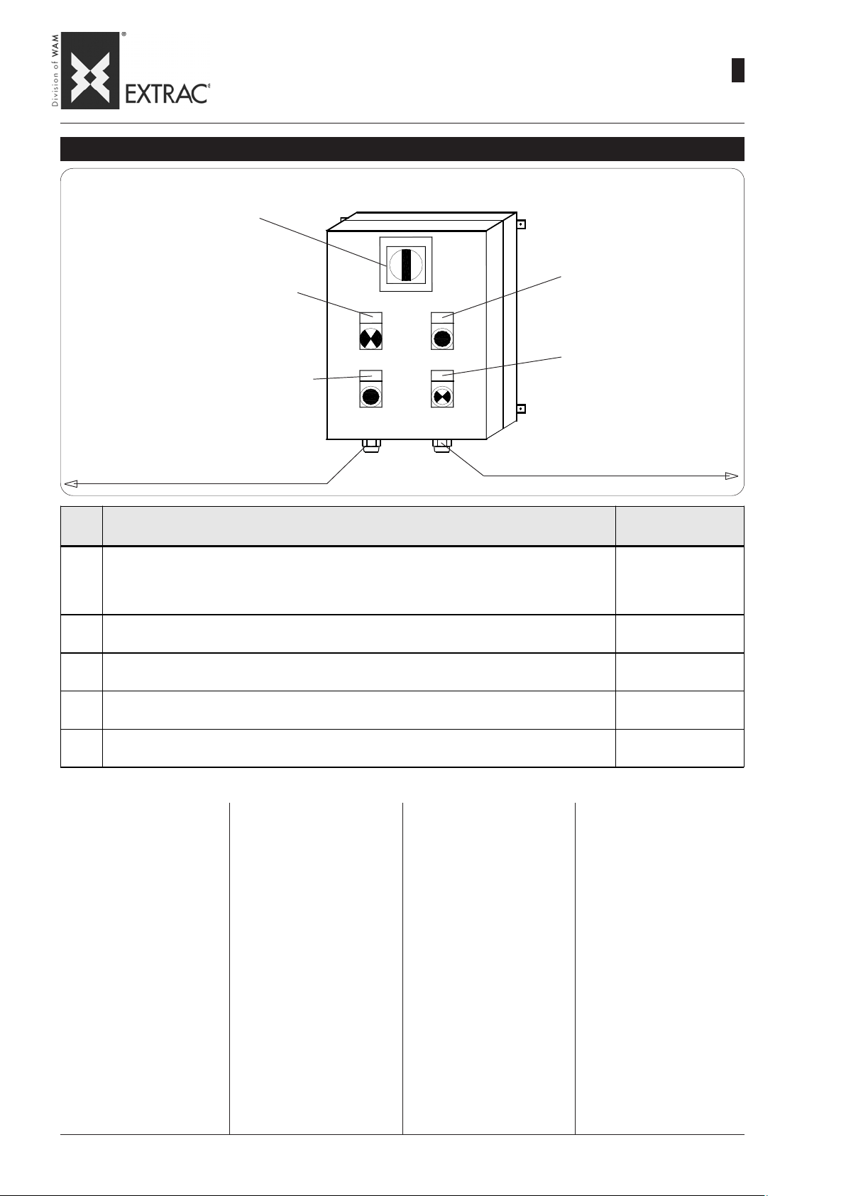
-
ELECTRIC-PNEUMATIC ACTUA TORS CONNECTION
-
SBB
ELEKTRISCHER UND PNEUMATISCHER ANSCHLUSS DER AUSTRAGHILFEN
-
RACCORDEMENT ÉLECTRIQUE-PNEUMATIQUE DES ACTIONNEURS
-
COLLEGAMENTO ELETTRO - PNEUMATICO ATTIVATORI
ELECTRIC CONTROL PANEL - ELEKTROSCHALTKASTEN - ARMOIRE ÉLECTRIQUE - QUADRO ELETTRICO
MAIN SWITCH
HAUPTSCHALTER
INTERRUPTEUR GÉNÉRAL
INTERRUTTORE GENERALE
CYCLE ST ART PUSHBUTTON
MAN./AUT . CYCLE SELECTOR
WAHLSCHALTER ZYKLUS HANDB../AUTOM.
SÉLEC. CHOIX CYCLE MAN. & AUTOM.
QS
TASTE FÜR ZYKLUS-START
BOUTON DÉBUT CYCLE
PULSANTE INIZIO CICLO
SELETT. SCELTA CICLO MAN. & AUTOM.
PG16
SB
CYCLE STOP PUSHBUTTON
TASTE FÜR ZYKLUS-STOP
BOUTON ARRÊT CYCLE
PULSANTE STOP CICLO
EMSA1
ELECTRIC POWER SUPPL Y INPUT
EINGANG FÜR STROMVERSORGUNG
ENTRÉE ALIMENTA TION ÉLECTRIQUE
INGRESSO ALIMENTAZIONE ELETTRICA
SINGLE/IN PAIRS CYCLE SELECT OR
WAHLSCHALTER ZYKLUS ABWECHS./SIMULTAN
SÉLECTEUR CHOIX CYCLE MAN. / AL T .
SELETT. SCELTA CICLO ALT. & SIMUL.
PNEUMATIC P ANEL POWER SUPPLY
VERSORGUNG PNEUMATIKSTEUERUNG
ALIMENTA TION ARMOIRE PNEUMATIQUE
ALIMENTAZIONE QUADRO PNEUMATICO
SA2
PG21
09.07
WA.14 M.
2
23
ITEM
POS.
MAIN SW ITCH - HAUPTSCHALTER
QS
INTERRUPTEUR GÉ NÉRAL - INTERRUTTORE GENERALE
CYCLE START PUSHBUTTON - TASTE FÜR ZYKLUS-START
SB
BOUTON DÉBUT CYCLE - PU LSANTE INIZIO CICLO
CYCLE STOP PUSHBUTTON - TASTE FÜR ZYKLUS-STOP
EM
BOUTON ARRÊT CYCLE - PULSANTE STOP CICLO
SINGLE/IN PAIRS CYCLE SELECTOR - WAHLSCHALTER ZYKLUS ABWECHSELND - SIMULTAN
SA1
SÉLECTEUR CHOIX C YCLE ALT. - SIMULT. - SELETTORE SCELTA CICLO ALTERNATIVO -SIMULTANEO
MAN./AUT. C YCLE SELECTOR - WAHLSCHALTER ZYKLUS MANUELL - AUTOMATISCH
SA2
SÉLECTEUR CHOIX C YCLE MAN. - AUT. - SELETTORE SCELTA CICLO MANU ALE - AUTOMATICO
DESCRIPTION - BENENNUNG - DÉSIGNATION - DENOMINAZI ONE
The control board comprises a
box with front door on which the
controls and operation indicators
are fitted.
Description of controls and
indicators:
SB/EM = PUSHBUTTONS:
controls with single operating mode
SA = SELECTORS:
double-function switches
QS = SWITCHES:
controls with two possible
positions.
Die elektrische Steuerung ist mit
einer Tür ausgestattet, auf der
sich die Bedienelemente und
Kontrollanzeigen befinden.
Beschreibung der Bedienelemente und Kontrollanzeigen:
SB/EM = DRUCKKNÖPFE:
Bedienelemente mit nur einer
Betriebsart.
SA = WAHLSCHAL TER:
Bedienelemente mit zwei Betriebsarten.
QS = SCHALTER:
Bedienelemente mit zwei
möglichen Positionen.
L`armoire électrique de commande est constituée d'un boîtier à porte frontale sur lequel
sont montés les commandes et
témoins de fonctionnement.
Description commandes et
indicateurs:
SB / EM = BOUTONS: comman-
des avec un seul mode de
fonctionnemnt.
SA= SÉLECTEURS: commuta-
teurs à deux fonctions.
QS=INTERRUPTEURS comman-
des à deux positions possibles.
COLOUR - FARBE
COULEUR - COLOR E
RED – YELLOW
ROT –GELB
ROUGE – JAUNE
ROSSO - GIALLO
BLACK - SCHWARZ
NOIR - NERO
RED - ROT
ROUGE - ROSSO
BLACK - SCHWARZ
NOIR - NERO
BLACK - SCHWARZ
NOIR - NERO
Il quadro elettrico di comando è
costituito da una cassetta con
portello frontale sul quale sono
montati dei comandi ed indicatori
di funzionamento.
Descrizione comandi ed indicatori:
SB / EM =PULSANTI:
sono comandi con un'unica
modalità di funzionamento
SA=SELETTORI:
sono commutatori a due funzioni.
QS=INTERRUTTORI:
sono comandi con due posizioni possibili.
Page 72
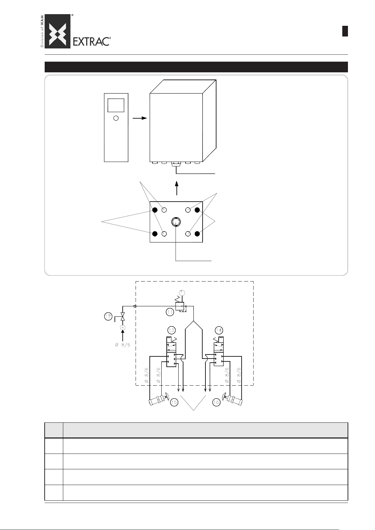
-
ELECTRIC-PNEUMATIC ACTUA TORS CONNECTION
-
SBB
ELEKTRISCHER UND PNEUMATISCHER ANSCHLUSS DER AUSTRAGHILFEN
-
RACCORDEMENT ÉLECTRIQUE-PNEUMATIQUE DES ACTIONNEURS
-
COLLEGAMENTO ELETTRO - PNEUMATICO ATTIVATORI
PNEUMATIC PANEL - PNEUMATIKSTEUERUNG - ARMOIRE PNEUMATIQUE - QUADRO PNEUMATICO
INLET
AIR
ELECTRIC POWER LINE
ELEKTR. VERSORGUNGSLEITUNG
LIGNE D'ALIMENT ATION ELECTRIQUE
LINEA DI ALIMENTAZIONE ELETTRICA
ELECTRIC POWER CYLINDER LH
PG21
VERSORGUNG SZYLINDER lks.
ALIMENT ATION VÉRIN G .
ALIMENTAZ. CILINDRO Sx
ELECTRIC POWER CYLINDER RH
VERSORGUNG ZYLINDER rts.
ALIMENTA TION CYLINDRE D.
ALIMENTAZIONE CILINDRO Dx
AIR OUTLET
LUFTAUSLASS
SORTIE AIR
USCITA ARIA
AIR OUTLET
LUFTAUSLASS
SORTIE AIR
USCITA ARIA
09.07
WA.14 M.
2
24
INLET ELECTRIC POWER LINE
EINGANG FÜR STROMVERSORGUNG
ENTRÉE CÂBLE ALIMENT A TION ÉLECTRIQUE
INGRESSO CAVO ALIMENTAZ. ELETTRICA
AIR INLET
LUFTEINLASS
ENTRÉE AIR
ENTRAT A ARIA
AIR OUTLET - LUFTAUSLASS
SORTIE AIR - USCITA ARIA
ITEM
POS.
5 WAY SOLENOID VALVE - 5 WEGE-MAGNETVENTIL
13/14
ÉLECTROVALVE À 5 VOIES - ELETTROVALVOLA 5 VIE
PRESSURE REDU CER - DRUCKMINDERER
11
RÉDUCTEUR DE PRESSION - RIDUTTORE DI PRESSIONE
PNEUM ATIC AC TIVATORS - PNEUMATISCHE AUSTRAGHILFEN
15-16
ACTIVATEURS PNEUMATIQUES - ATTIVATORI PNEUMATICI
1/2" MANUAL BALL VALVE ( NON STANDARD ) - 1/2" KUGELHAHN MANUELL ( KEIN STANDARD )
17
VANNE SP HÉRIQUE MANUELLE 1/2" ( NON STAND A R D ) - VALVOLA A SFERA MANU ALE 1/2" ( NON STANDARD )
DESCRIPTION - BENENNUNG - DÉSIGNATION - ENOMINAZIONE
Page 73
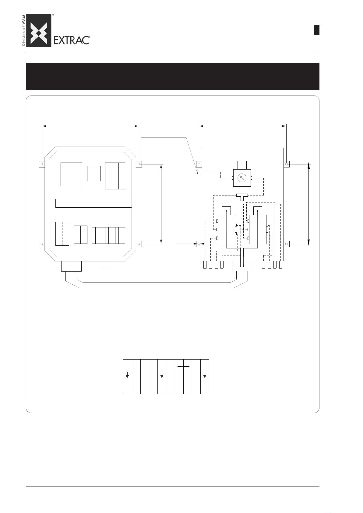
-
ELECTRIC-PNEUMATIC ACTUA TORS CONNECTION
-
SBB
ELEKTRISCHER UND PNEUMATISCHER ANSCHLUSS DER AUSTRAGHILFEN
-
RACCORDEMENT ÉLECTRIQUE-PNEUMATIQUE DES ACTIONNEURS
-
COLLEGAMENTO ELETTRO - PNEUMATICO ATTIVATORI
TERMINAL BOARD ELECTRIC CONTROL P ANEL - PNEUMA TIC CONTROL P ANEL
KLEMMENLEISTE ELEKTROSTEUERUNG - PNEUMATIKSTEUERUNG
BORNIER ARMOIRE ÉLECTRIQUE - ARMOIRE PNEUMATIQUE
MORSETTIERA QUADRO ELETTRICO - QUADRO PNEUMATICO
09.07
WA.14 M.
2
25
PG21
TC+FU2
FU1
KA0
254
QS
25 x 60
KA1
KT1
KT2
MORSETTIERA
TERMINAL BOARD
PG16
KT3
INGRESSO
ARIATUBO Ø8x6
185
Ø
PVC 20x26 Mt 0.8
254
REG.
MAN.
185
5
4
1
2
3
.
6
6
YV1 YV2
5
4
1
2
3
PG21
TERMINAL BOARD
KLEMMENLEISTE
PLAQUE À BORNES
MORSETTIERA
RST 6007
Page 74
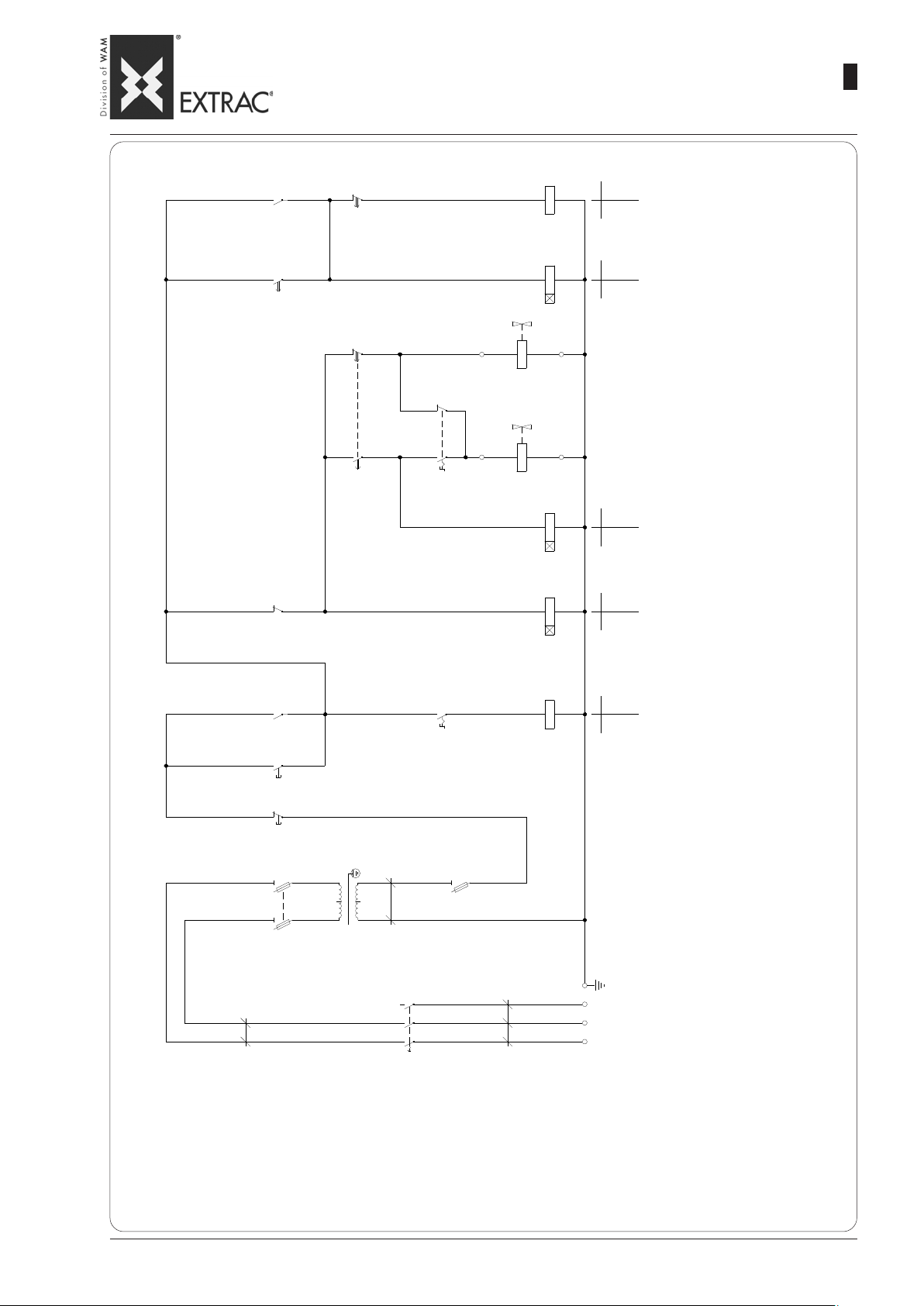
-
1
ELECTRIC-PNEUMATIC ACTUA TORS CONNECTION
-
SBB
9
1
-
A
1
K
3
0
6
2
-
T
1
K
0
ELEKTRISCHER UND PNEUMATISCHER ANSCHLUSS DER AUSTRAGHILFEN
-
RACCORDEMENT ÉLECTRIQUE-PNEUMATIQUE DES ACTIONNEURS
-
COLLEGAMENTO ELETTRO - PNEUMATICO ATTIVATORI
A
8
3
T
K
9
8
3
T
K
K
5
1
C
0
N
O
0
9
-
N
1
0
C
N
O
9
-
N
1
0
ARMS CYCLE STOP AUXILIARY RELA Y
HILFSRELAIS ZYKLUSENDE ARME
RÉLAIS AUXILIAIRES FIN DE CYCLE BRAS
RELE' AUSILIARI FINE CICLO BRACCI
CYCLE RESET RELAY
ZEITSCHALTER ZYKLUS-RESET
TEMPO RESET CYCLE
TIMER RESET CICLO
09.07
WA.14 M.
2
26
7
7
0
1
V
Y
ARM 2 SOLENOID VAL VE
MAGNETVENTIL ARM 2
ÉLECTROVANNE BRAS 2
ELETTROVALVOLA BRACCIO 2
6
ARM 1 SOLENOID VAL VE
6
1
T
K
1
A
S
5
9
1
-
A
1
K
0
4
4
0
2
V
Y
C
N
2
T
K
1
T
K
O
8
-
N
1
0
7
-
1
C
0
N
O
6
-
N
1
0
MAGNETVENTIL ARM 1
ÉLECTROVANNE BRAS 1
ELETTROVALVOLA BRACCIO 1
ARM 2 FORWARD TIMER
ZEITSCHALTER VORWÄRTS ARM 2
TEMPO A V ANT BRAS 2
TIMER AVANTI BRACCIO 2
ARM 1 FORWARD TIMER
ZEITSCHALTER VORWÄRTS ARM 1
TEMPO A V ANT BRAS 1
TIMER AVANTI BRACCIO 1
3
0
A
4
0
-
A
1
K
0
3
A
3
B
S
3
B
3
2
A
S
K
C
N
O
4
-
N
1
0
AUTOMA TIC CYCLE RELAY
RELAIS AUTOMATIKZYKLUS
RÉLAIS CYCLE AUTOMA TIQUE
RELE' CICLO AUTOMA TICO
A
3
0
S
0
R
M
E
O
1
U
A
F
2
E
N
Ø
5
.
1
A
V
P
C
0
5
T
R
0
0
4
0
3
2
P
0
S
R
Ø
1
2
1
0
2
1
S
Q
2
U
A
F
4
1
0
A
6
1
2
0
E
N
Ø
5
.
1
E
P
T
S
R
POWER SUPPLY
VERSORGUNG
ALIMENTATION
ALIMENTAZIONE
NOTE: The magneto-thermal differential cutout switch for this electric panel must be provided by the final Customer.
HINWEIS: Der Fehlerstrom-Schutzschalter für diesen Schaltkasten ist eine Leistung, für die der Endanwender zu sorgen hat (gehört nicht zum Lieferumfang).
REMARQUE: L'interrupteur de protection magnétothermique différentielle de cette armoire électrique est à la charge du Client utilisateur final.
NOTE: La protezione magnetotermica differenziale di questo quadro elettrico é a carico del Cliente utilizzatore finale.
Page 75
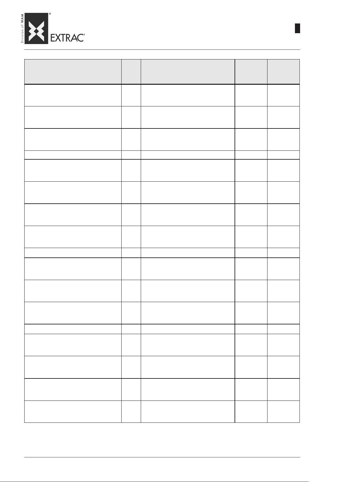
SBB
-
ELECTRIC-PNEUMATIC ACTUA TORS CONNECTION
-
ELEKTRISCHER UND PNEUMATISCHER ANSCHLUSS DER AUSTRAGHILFEN
-
RACCORDEMENT ÉLECTRIQUE-PNEUMATIQUE DES ACTIONNEURS
-
COLLEGAMENTO ELETTRO - PNEUMATICO ATTIVATORI
09.07
WA.14 M.
2
27
KURZBEZEICHNUNG STROMLAUFPLAN
WIRING DIAGRAM CODE
ENTRÉE CÂBLE ALIMENTATION ELECT.
SIGLA SCHEMA ELETTRICO
QS 1
QS 1
QS 1
TC 1
Q.ty
Menge
Q.té
Q.tà
2
2
8
DESCRIPTION
BENENNUNG
DÉSIGNATION
DENOMINAZIONE
Box 300x220x120 mm
Kunststoffgehäuse 300 x 320 x 120 mm
Boîtier plastique 300x220x120 mm
Scatola plastica 300x220x120 mm
Internal panel
Bodenplatte
Plaque de fond
Piastra di fondo
Fixing support
Befestigungsbügel
Étrier de fixation
Staffa di fissaggio
Main switch 3X 16A
Schalter 3 x 16 A
Interrupteur 3x16 A
Interruttor e 3 X16A
Yellow/red dial
Gelb rote Anzeige
Cache jaune/rouge
Mostrina giallo/rossa
Main switch extension
Verlängerung Kunststoffwelle
Rallonge arbre plastique
Prolunga albero plastica
Transformer 50VA
Transformator 50 VA
Transformateur 50 VA
Trasformatore 50VA
TYPE
TYP
TYPE
TIPO
GW44209 GEWISS
GW44617 GEWISS
GW44621 GEWISS
LA216-1753 BRETER
LFS2-N.6.1753 BRETER
LA2-G2853 BRETER
50WP/G+F ITALTRAFO
BRAND
FABRIKAT
MARQUE
MARCA
FU1 1
FU1 2
FU2 1
KA0 KA1 2
KA0 KA1 2
KT1 KT2 KT3 3
SA1 SA2 2
BiPole fuse holder
Zweipoliger Sicherungshalter
Porte fusible bipolaire
Portafusibile bipol are
Fuse GL 10x38 2A
Sicherung GL 10x38 2A
Fusible GL 10x38 2A
Fusibile GL 10x38 2A
Glass Fuse 4A
Glassicherung 4A
Fusible de verre 4A
Fusibile di vetro 4A
Base for 2-contact relay
Sockel für Relais 2SC
Soc le pour rélai s 2 SC
Zoccolo per relè 2SC.
2-contact relay 24VAC
Relais mi t 2 Kontakten 24V WS
Rélais 2 contacts 24VCA
Relè 2 contatti 24VAC
Multiscale Timer 24 240VAC/DC
Mehrbereichszeitschalter 24V WS/GS
Temporisateur 24 240VCA
Timer multiscala 24 240VAC/DC
Selector 0-1
Stabiler Wahlschalter 0-1
Sélecteur stable 0-1
Selettore stabile 0-1
24212
CH10-2A
4A5X20
95.45 FINDER
40.52.8.024 FINDER
H3DE-S1 OMRON
P2T-S120 OMRON
ELETTRO
ITALIA
Page 76

SBB
-
ELECTRIC-PNEUMATIC ACTUA TORS CONNECTION
-
ELEKTRISCHER UND PNEUMATISCHER ANSCHLUSS DER AUSTRAGHILFEN
-
RACCORDEMENT ÉLECTRIQUE-PNEUMATIQUE DES ACTIONNEURS
-
COLLEGAMENTO ELETTRO - PNEUMA TICO A TTIV A TOR I
09.07
WA.14 M.
2
28
KURZBEZEICHNUNG STROMLAUFPLAN
WIRING DIAGRAM CODE
ENTRÉE CÂBLE ALIMENTIMENTATION ELECT.
SIGLA SCHEMA ELETTRICO
SB 1
EM 1
HL0 SB2 1
SA1 SA2 SB EM 4
SA1 SA2 SB EM 4
Q.ty
Menge
Q.té
Q.tà
3
2
DESCRIPTION
BENENNUNG
DÉSIGNATION
DENOMINAZIONE
Black button
Schwarze Taste
Bouton no ir
Pulsante nero
Red button
Rote Taste
Bouton rouge
Pulsante rosso
Contact 1NA
Kontakt 1NA
Contact 1NA
Contatto 1NA
Contact 1NA
Kontakt 1S
Contact 1NA
Contatto 1NA
Lamp BA9S 30V
Lampe BA9S 30V
Lampe BA9S 30V
Lampadina BA9S 30V
Plate holder
Schildhalter
Porte plaquette
Porta targhetta
Glass
Glas
Verre
Vetrino
TYPE
TYP
TYPE
TIPO
P2T-B102 LOVATO
P2T-B2104 LOVATO
M2T-C10 LOVATO
M2T-C01 LOVATO
BA9S 30V
PTAR22
T1527V
MAKE
FABRIKAT
MARQUE
MARCA
MODERNO
TECNICA
MODERNO
TECNICA
Spring terminal ZDU 2.5
7
3
1
2
1
2
1
Klemm e mit Feder ZDU 2.5
Borni e r à re s s o rt ZD U 2.5
Morsetto a mol la ZD U 2.5
Spring ground term. ZPE 2.5
Erdungsklemme mit Feder ZPE 2.5
Borner de terre à ressort ZPE 2.5
Morsetto terra a molla ZPE 2.5
Terminal plate ZDU 2.5
Klemmenl ei ste ZDU 2.5
Plaque à cosse ZDU 2.5
Piastra termi n ale ZDU 2 .5
Terminal lock ZEW35
Klemm ensperre ZWE35
Serre borne ZWE35
Ferma morsetto ZEW35
Cable-press PG16
Kabelverschraubung PG16
Serre fil PG16
Pressacavo PG16
Al fa nylon union P G 21
Alfa-Nylonanschluss PG21
Raccord a lfa Nylon PG21
Raccordo alfa nylon PG21
Metal ring PG16
Metallringmutter PG16
Bague en métal PG16
Ghiera metallo PG16
160851 WEIDMULLER
160864 WEIDMULLER
160874 WEIDMULLER
954000 WEIDMULLER
POP-PG16 RTA
81028 RTA
86625 RTA
Page 77
SBB
-
ELECTRIC-PNEUMATIC ACTUA TORS CONNECTION
-
ELEKTRISCHER UND PNEUMATISCHER ANSCHLUSS DER AUSTRAGHILFEN
-
RACCORDEMENT ÉLECTRIQUE-PNEUMATIQUE DES ACTIONNEURS
-
COLLEGAMENTO ELETTRO - PNEUMATICO ATTIVATORI
09.07
WA.14 M.
2
29
KURZBEZEICHNUNG STROMLAUFPLAN
WIRING DIAGRAM CODE
ENTRÉE CÂBLE ALIMENTATION ELECT.
SIGLA SCHEMA ELETTRICO
MAN 1
REG 1
REG 1
YV1 YV2 2
YV1 YV2 2
YV1 YV2 2
Q.ty
Menge
Q.té
Q.tà
2
1 mt
4 mt
5
4
4
12
1
3 mt
DESCRIPTION
BENENNUNG
DÉSIGNATION
DENOMINAZIONE
Metal ring P G2 1
Metallringmutter PG21
Bague en métal PG21
Ghie r a metallo PG2 1
Grey PVC sheath 20x26mm
Graue PVC-Hül le 20x26 mm
Gaine PVC 20x26 mm grise
Guaina PVC 20x26mm grigia
Flame-retardant cable 3x1
Graues flamm widriges Kabel 3x1
Câble antifeu 3x1 gris
Cavo antifiamma 3x1 grigio
Manometer 0.4 bar 1/8"
Manometer 0,4 bar 1/8"
Manomètre 0,4 bar 1/8"
Manometro 0.4 bar 1/8"
Pressure regulator
Druckregler
Régulateur de pression
Regolatore di pressione
Pressure regulator support
Bügel für Druckregler
Étrier pour régulateur de pression
Staffa per regolatore di pressione
Solenoid valve SOV 35 SOS OO
Magnetventil SOV 35 SOS OO
Électrovanne SOV 35 SOS OO
Elettrovalvola SOV 35 SOS OO
Coil for solenoid valve
Spule für Magnetventil
Bobine pour électrovanne
Bobina per elettrovalvola
Connect or for coi l
Steckverbinder für Spule
Connecteur pour bobine
Connettore per bobina
Union pipe Ø8
Wanddurchführung Rohr Ø8
Raccord passe paroi tube Ø8
Raccordo passaparete tubo Ø8
Leak SFE 1/4"
Entlüftung SFE 1/4"
Évent SFE 1/4"
Sfiato SFE 1/4"
Female union 1/4" pipe Ø8
Anschluß 1/4" Rohr Ø8
Raccord femelle 1/4" tube Ø8
Raccordo femmina 1/4" tubo Ø8
Union 90x8 1/4" pipe Ø8
Anschluß 90x8 1/4" Rohr Ø8
Raccord 90x8 1/4" tube Ø8
Raccordo 90x8 1/4" tubo Ø8
T-Union pipe Ø8
T-Stück Rohr Ø8
Raccord en Té tube Ø8
Raccordo a T tubo Ø8
Light blue Elastolan pipe 8x6
Hellblauer Elastolan-Schlauch 8x6
Tube Elastolan 8x6 bleu ciel
Tubo Elastolan 8x6 azzurro
TYPE
TYP
TYPE
TIPO
86626 RTA
PVC20GR RTA
3x1GR
0.4 bar 1/8 WIKA
MRBIT 1/4-0.4 METAL WORK
SF 1/4 METAL WORK
SOV35SOSOO METAL WORK
22D8-2450 METAL WORK
22STD METAL WORK
RL108 METAL WORK
SFE-1/4 METAL WORK
RL2-8-1/4 METAL WORK
RL34-8-1/4 METAL WORK
RL228 METAL WORK
ELASTOLAN
8x6AZ
MAKE
FABRIKAT
MARQUE
MARCA
METAL WORK
Page 78
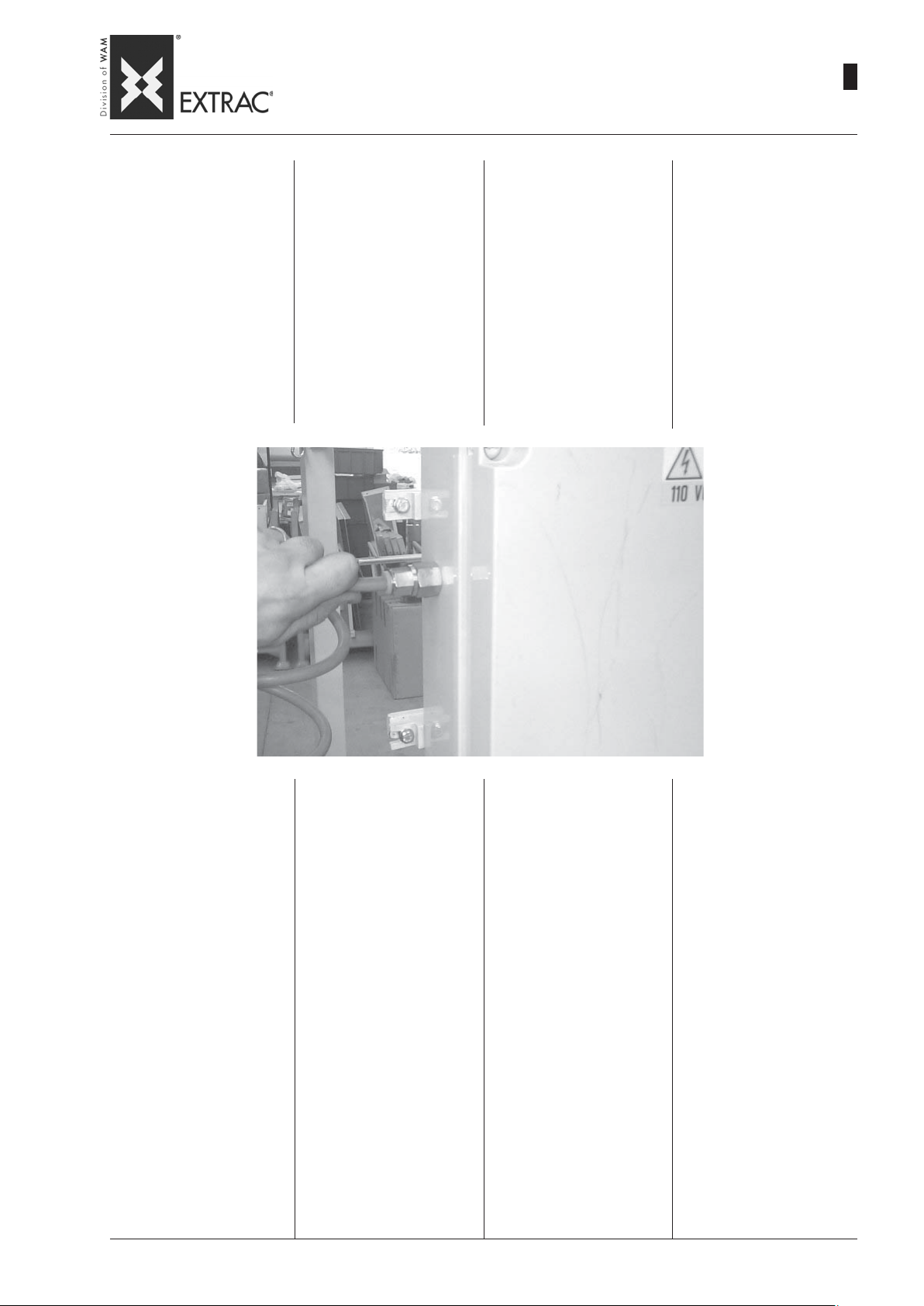
SBB
-
ELECTRIC-PNEUMATIC ACTUA TORS CONNECTION
-
ELEKTRISCHER UND PNEUMATISCHER ANSCHLUSS DER AUSTRAGHILFEN
-
RACCORDEMENT ÉLECTRIQUE-PNEUMATIQUE DES ACTIONNEURS
-
COLLEGAMENTO ELETTRO - PNEUMATICO ATTIVATORI
09.07
WA.14 M.
2
30
PNEUMATIC POWER
The compressed air coupling on
the equipment is achieved by
means of a hose connector pipe
having internal diameter 8x6mm.
COMPRESSED AIR PRESSURE
- Minimum 5 bar
- Maximum 6 bar
It is advisable to connect a man-
ual cut-off device on the air infeed line (ball valve or similar) to
facilitate subsequent maintenance operations.
DRUCKLUFTVERSORGUNG
Die Einleitung der Druckluft auf
die Vorrichtung erfolgt mit einem
Gummistutzen mit Innendurchmesser 8x6 mm.
DRUCK DER DRUCKLUFT
- Minimum 5 bar
- Maximum 6 bar
Auf die Zufuhrleitung der Druck-
luft sollte ein von Hand zu betätigendes Absperrorgan (Kugelventil oder ähnliches) installiert
werden, das die anschließenden
Wartungsarbeiten vereinfacht.
ALIMENT ATION PNEUMA TIQUE
Le branchement de l’air comprimé sur les filtres est réalisé par
un tube de diamètre 8x6 mm.
PRESSION AIR COMPRIMÉ
- Minimum 5 bar
- Maximum 6 bar
Il est conseillé d ‘insérer sur la
circuit d’ alimentation de l’air un
dispositif de coupure manuelle
(robinet à boisseau ou similaire)
pour faciliter les opérations d’
entretien.
ALIMENTAZIONE PNEUMATICA
L’ innesto dell’ aria compressa
sulla macchina è realizzato da
un tubo portagomma di diametro
8x6 mm.
PRESSIONE ARIA COMPRESSA
- Minimo 5 bar
- Massimo 6 bar
É consigliabile inserire sulla linea
di alimentazione della aria un organo di intercettazione manuale
(valvola a sfera o simile) che
faciliterà le successive operazioni di manutenzione.
The compressed air must be:
1- Clean
Free of impurities which may
damage the solenoid valve.
Warning: Before connecting the
compressed air to the equipment,
empty the piping.
2 - Dehumidified
However, it is advisable to use a
condensate trap.
3 - Oil-free
The presence of oily substances in the air may cause precocious, irreversible clogging.
Die Druckluft muß sein:
1- Sauber
Sie darf keinen Schmutz enthalten, der das Magnetventil des
Filters beschädigen könnte.
Achtung: Vor dem Anschluß
der Druckluft an die Vorrichtung
die Leitungen entleeren.
2 - Trocken
Es sollte aber besser ein Kondensatabscheider benutzt werden.
3 - Ölfrei
Das Vorhandensein von Ölteilchen in der Druckluft würde unweigerlich zum vorzeitigen Verstopfen führen.
L’ air comprimé doit être :
1- Propre
Sans impuretés pouvant endommager l'électrovanne du filtre
Attention: avant de brancher
l'air comprimé au filtre vider les
tuyauteries
2 - Déshumidifié
Il faut prévoir l'utilisation d'un
séparateur d'eau de condensation.
3 - Déshuilé
La présence de substances huileuses dans l'air constitue une
cause de colmatage précoce et
irréversible.
L’ aria compressa deve essere:
1- Pulita
Esente da impurità che potrebbe
danneggiare l' elettrovalvola
Attenzione: prima di collegare
l’ aria compressa alla macchina
vuotare le tubazioni
2 - Deumidificata
E’ opportuno comunque prevedere l’ utilizzo di un separatore
di condensa.
3 - Disoleata
La presenza di sostanze oleose
nell’ aria costituirebbe una causa d’ intasamento precoce ed irreversibile.
Page 79

SBB
-
ST ART-UP
-
INBETRIEBNAHME
-
MISE EN SERVICE DE LA MACHINE
-
MESSA IN SERVIZIO DELLA MACCHINA
09.07
WA.14 M.
2
31
PRELIMINARY OPERATIONS
PRIOR TO ST ART -UP
Before starting up the plant, it is
essential to carry out a series
of checks to prevent problems
or risks.
Ascertain that all the equipment
components are positioned and
fixed correctly.
Carefully check all the connections, the rubber hoses and fixtures.
If pneumatic activators are provided, special attention must be
paid to the compressed air connections.
WARNINGS
1 - For proper functioning of the
FIBC unloader, the equipment
downline must be capable of
removing all the product extracted from the FIBC.
VORBEREITUNG DER INBETRIEBNAHME
Vor der Inbetriebnahme des Systems müssen eine Reihe von
Kontrollen vorgenommen werden, um etwaige Probleme oder
Risiken zu vermeiden.
Sicherstellen, daß alle Bestandteile der Vorrichtung korrekt aufgestellt und befestigt sind.
Alle Anschlüsse, Gummischläuche und entsprechenden Befestigungen sorgfältig prüfen.
Falls pneumatische Aus-traghilfen vorgesehen sind, ist
besonders auf die pneumatischen Anschlüsse zu achten.
VORSICHT
1 - Für den korrekten Betrieb der
Big-Bag-Entleerstation müssen
die Geräte stromab unbedingt
in der Lage sein, das aus dem
Big-Bag entleerte Produkt aufzunehmen.
OPERATIONS PRELIMINAIRES
A LA MISE EN MARCHE
Avant d’effectuer la mise en
marche de l’installation il est important de faire une série de
contrôles pour prévenir les problèmes et les risques.
S’ assurer que tous les composants de l’équipement sont bien
positionnés et fixés correctement.
Vérifier soigneusement tous les
raccordements, les tubes en
caoutchouc et leurs fixations.
Si l’équipement est équipé d’activateurs pneumatiques, faire
tout particulièrement attention
aux raccordements pneumatiques.
RECOMMANDATIONS
1 - Pour un bon fonctionnement
du vide-sac il est indispensable que les machines en aval
soient en mesure d’évacuer le
produit extrait des sacs.
OPERAZIONI PRELIMINARI
ALL’ AVVIAMENTO
Prima di effettuare l’ avviamento
dell’ impianto è importante che
vengano eseguiti una serie di
controlli al fine di prevenire problemi o rischi.
Accertarsi che tutti i componenti
della macchina siano collocati in
modo opportuno e correttamente fissati.
Verificare accuratamente tutti gli
allacciamenti, i tubi gomma ed i
relativi fissaggi.
Nel caso siano previsti gli attivatori pneumatici porre particolare
attenzione ai collegamenti pneumatici.
AVVERTENZE
1 - Per un buon funzionamento
dello svuota big bag è indispensabile che le macchine a
valle siano in grado di evacuare il prodotto estratto dal big
bag.
2 - The connection between the
outlet spout of the FIBC Unloader and any other equipment positioned downline must be made
using a flexible connector to
prevent vibrations of the hopper from being transmitted to
the equipment.
3 - It is advisable to provide a
butterfly valve or slide valve
at the hopper outlet in order to
prevent outflow of product
when the motovibrator stops
operating.
2 - Der Anschluß zwischen dem
Auslauf der Big-Bag-Entleerungsstation und dem stromab
eingebauten Gerät ist mittels einer flexiblen Verbindung vorzunehmen, damit die Vibrationen des Trichters nicht auf das
Gerät übertragen werden.
3 - Am Trichterauslauf sollte ein
Flachschieber oder eine Drehklappe vorgesehen werden,
damit kein Produkt mehr ausströmt, wenn der Vibrationsmotor einge-schaltet wird.
2 - La liaison à la bouche de sor-
tie du vide-sacs et de toute machine placée en aval doit être
réalisée à travers un raccord
flexible de manière à éviter que
les vibrations de la trémie
soient transmises à l’équipement.
3 - Il est conseillé de prévoir en
sortie de la trémie une vanne
papillon ou une vanne à guillotine pour éviter la sortie de produit lors de l’arrêt du fonctionnement du moto-vibrateur.
2 - Il collegamento tra la bocca
di scarico dello svuota big bag
e qualunque macchina posizionata a valle dovrà essere effettuata mediante un raccordo
flessibile in modo da evitare
che le vibrazioni della tramoggia vengano trasmesse alla
macchina stessa.
3 - Si consiglia di prevedere allo
scarico della tramoggia una
valvola a farfalla o una serranda a ghigliottina in modo da evitare fuoriuscita di prodotto all’
arresto del funzionamento del
motovibratore.
Page 80
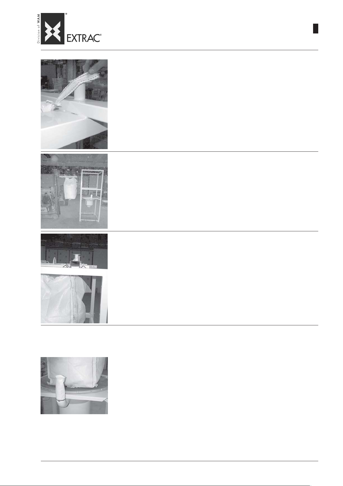
SBB
-
START -UP - OPERA TION
-
INBETRIEBNAHME - BETRIEB
-
MISE EN SERVICE - FONCTIONNEMENT
-
MESSA IN SERVIZIO - FUNZIONAMENTO
1) Lift the fixing cross of the FIBC above the FIBC by means of a forklift truck or a
hoist, and fix the slings to the hooks as shown in the Figure.
1) Das Kreuzstück zur Befestigung des Big-Bag per Gabelstapler oder Flaschenzug
über denselben heben und die Gurte zum Einhaken wie in der Abbildung gezeigt
befestigen.
1) Soulever le croisillon de fixation du BIG-BAG au-dessus du BIG-BAG au moyen
d’un chariot élévateur ou d’un palan; fixer ensuite les sangles dans les crochets,
comme l’indique la figure.
1) Sollevare la apposita crociera di fissaggio del BIG-BAG al di sopra del BIG-BAG
stesso mediante carrello elevatore o paranco, e fissare le bretelle agli agganci
come mostrato in figura.
2) Lift the cross on which the FIBC is hooked by means of a forklift truck or hoist and insert
it in the supporting frame.
2) Mit dem Gabelstapler oder dem Flaschenzug das Kreuzstück heben, in den der Big-Bag
eingehängt ist, und ihn in die T ragstruktur einführen.
09.07
WA.14 M.
2
32
2) A l’aide d’un chariot élévateur ou d’un palan soulever le croisillon sur lequel est accroché
le BIG-BAG et l’introduire dans la structure de soutien.
2) Sollevare col muletto o paranco la crociera sul quale è agganciato il BIG-BAG e introdur-
lo nella struttura di sostegno.
3) While inserting the frame, take care to fit the tailpieces of the cross in the seats
provided (MODEL S).
3) Beim Einführen darauf achten, dass sich die Vorsprünge des Kreuzstücks
innerhalb der vorgesehenen Winkeleisen befinden (MODELL S).
3) En phase d’introduction, veiller à encastrer les extrémités du croisillon dans
leurs sièges (MODELE S).
3) In fase di introduzione avere cura di incastrare le appendici della crociera nelle
apposite sedi (MODELLO S).
4) In the working position the FIBC must only rest on the seal and not exert its weight on it. If this is not
the case, modify the position of the removable frame to obtain proper stretching of the FIBC. In the
version with hoist it is sufficient to modify the length of the chain. For other versions, it shall be the
responsibility of the plant technician or the user to use structures or forklift trucks of suitable height to
ensure this condition.
4) Es ist wichtig, daß der Big-Bag in der Arbeitsstellung auf der Dichtung nur leicht aufliegt und nicht mit
seinem Gewicht auf sie drückt. Andernfalls ist die Einstellung des ausziehbaren Gestells so weit zu
verändern bis die richtige Streckung des Big-Bag erreicht ist. In der Version mit Seilwinde muß lediglich
die Kettenlänge angepaßt werden. Für die anderen Versionen muss der Anlagenbauer bzw. der
Betreiber dafür sorgen, dass Strukturen oder Gabelstapler geeigneter Höhe verwendet werden, die
diesen Zustand gewährleisten.
4) Il est très important que le Big-Bag en position de travail soit seulement appuyé sur le joint et qu'il ne
repose pas de tout son poids sur celui-ci. Dans le cas contraire modifier la position du châssis
démontable jusqu'à obtenir une juste tension du Big-Bag. Dans la version à palan il suffit de
modifier la longueur de la chaîne. Pour les autres versions, l’installateur ou l’utilisateur devront se
servir de structures ou de chariots élévateurs d’une hauteur appropriée pour garantir cette condition.
4) É molto importante che il BIG-BAG, in posizione di lavoro, sia solo appoggiato sulla guarnizione e
che non gravi col proprio peso sulla stessa. In caso contrario modificare la posizione del telaio
sfilabile fino ad ottenere un giusto tensionamento del Big-Bag. Nella versione con paranco sarà
sufficente modificare la lunghezza della catena. Per le altre versioni sarà cura dell’impiantista o
dell’utilizzatore provvedere ad utilizzare strutture o carrelli elevatori di altezza adeguata a garantire
questa condizione.
Page 81
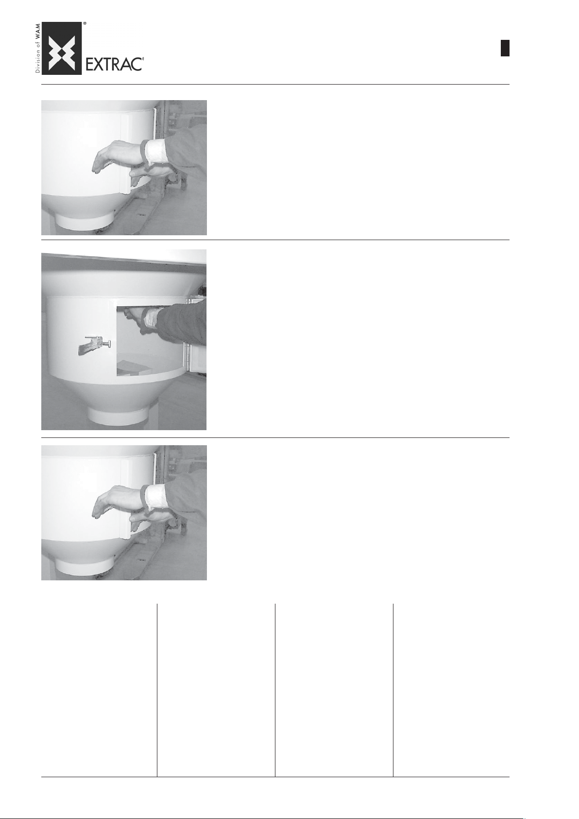
SBB
-
ST ART-UP - OPERA TION
-
INBETRIEBNAHME - BETRIEB
-
MISE EN SERVICE - FONCTIONNEMENT
-
MESSA IN SERVIZIO - FUNZIONAMENTO
5) Open the hatch.
5) Inspektionsklappe öffnen.
5) Ouvrir la trappe en actionnant le crochet prévu à cet effet.
5) Aprire il portello agendo sull' apposito gancio.
6) Extract the FIBC outlet spout and untie the cord to allow the product to start
flowing out.
09.07
WA.14 M.
2
33
6) Die Auslaßöffnung des Big-Bag herausziehen und die Verschlußleine öff-
nen, damit das Produkts langsam herausströmen kann.
6) Extraire la bouche de sortie du Big-Bag et délacer le cordon de fermeture de
manière à faire tomber la première partie de produit.
6) Estrarre la bocca di scarico del Big-Bag e slacciarne il cordone di chiusu-
ra in modo da fare defluire lentamente la prima parte di prodotto.
7) Close the hatch and start up the motovibrator to begin emptying the FIBC.
7) Die Klappe wieder verschließen und den Vibrationsmotor starten, um mit
der eigentlichen Entleerung zu beginnen.
7) Fermer la trappe en agissant sur le crochet prévu à cet effet et commencer
le vidage en mettant en marche le motovibrateur.
7) Chiudere il portello agendo sull' apposito gancio ed iniziare lo svuotamen-
to avviando il motovibratore.
Operation of the motovibra-tor
will be cyclic or continuous according to the flow required. At
the end of the emptying process, it is advisable to continue to
operate the motovibrator for another one or two minutes in order to remove any product remaining in the folds of the FIBC.
Do not start up the motovibrator
without the FIBC or without product.
To unload the FIBC empty the
hopper completely, then
proceed with the operations
indicated in reverse order.
Der Vibrationsmotor arbeitet je
nach dem geforderten Durchsatz
zyklisch oder im Dauerbetrieb.
Am Ende der Entleerphase sollte
der Vibrationsmotor noch 1 oder
2 Minuten weiterlaufen, um die
Restmenge auszutragen, die in
den Sackfalten verblieben ist.
Den Vibrationsmotor nicht einschalten, wenn kein Sack oder
kein Produkt vorhanden ist.
Zur Entfernung des Big-Bag
den Trichter ganz entleeren,
um die beschriebenen Vorgänge dann in umgekehrter
Reihenfolge vorzunehmen.
Le fonctionnement du moto-vibrateur sera cyclique ou continu
suivant le débit requis. Il est conseillé, à la fin du vidage, de faire
fonctionner le motovibrateur encore 1 à 2 minutes pour extraire
le produit qui est resté dans les
plis du sac. Ne pas mettre le
motovibrateur en marche en l’absence de Big Bags ou sans produit.
Pour décharger le Big-Bag vider complètement la trémie
puis procéder dans l’ordre
inverse aux opérations indiquées.
Il funzionamento del motovibratore sarà ciclico o in continuo a
seconda della portata richiesta.
Si consiglia, al termine dello svuotamento, di far funzionare ancora il motovibratore per 1 o 2 minuti al fine di estrarre l’ eventuale prodotto rimasto nelle pieghe
del big bag. Non avviare il motovibratore in assenza di Big Bag
o senza prodotto.
Per scaricare il BIG-BAG
svuotare completamente la
tramoggia poi procedere in
senso contrario alle operazioni indicate.
Page 82
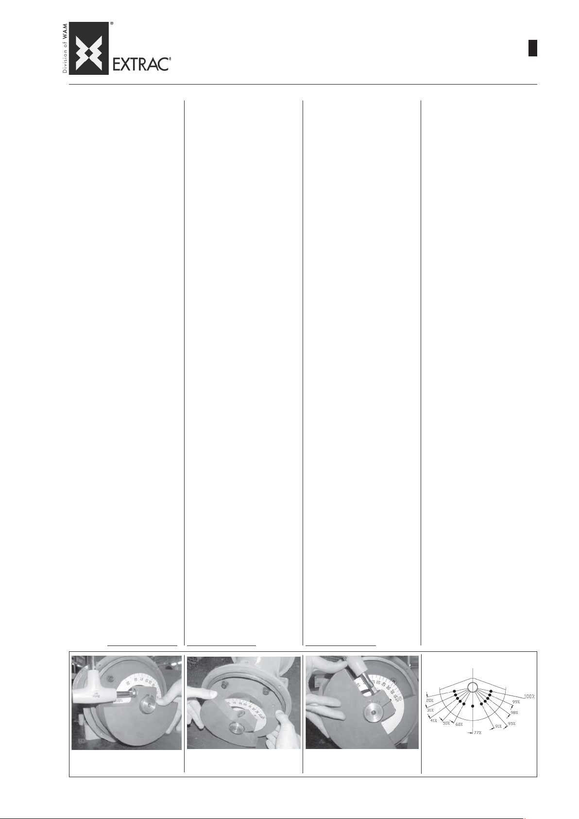
SBB
-
START -UP - ADJUSTING THE ELECTRIC VIBRA T OR
-
INBETRIEBNAHME - EINSTELLUNG DES UNWUCHTMOTORS
-
MISE EN SERVICE - REGLAGE DU MOTOVIBRA TEUR
-
MESSA IN SERVIZIO - REGOLAZIONE MOT OVIBRA TORE
09.07
WA.14 M.
2
34
If, during operation, there is a problem with downflow of the product, the
motovibrator can be adjusted, by increasing or decreasing its intensity
of vibration.
PROCEDURES FOR ADJUSTING
MOTOVIBRATOR
The motovibrator installed is of the
variable weights type; it is therefore
necessary to change the degree of
intensity of vibrations according to
the method described in the (enclosed) USE AND MAINTENANCE
manual supplied by the Manufacturer.
The value of regulation of the motovibrator fitted on the FIBC, is closely
linked to the conditions of use.
The adjustment must be made before start-up.
The parameters to be taken into consideration are:
- Type of product;
- Humidity;
- Temperature;
- FIBC storage time;
- Flow rate;
- FIBC dimensions.
The adjustment defined by the Manufacturer during the acceptance test
phase is 70%.
If it is necessary to change this value, it is advisable to proceed gradually.
If the results are not satisfactory,
before proceeding with another adjustment, empty the product from the
hopper in order to avoid residue from
previous tests.
THE OPERATION MUST BE CARRIED OUT EXCLUSIVELY BY QUALIFIED PERSONNEL, WITH THE
POWER SUPPLY DISCONNECTED.
- Remove the side covers after unscrewing the screws.
- Slacken the Allen nut (photo 1) and
move the mobile mass (photo 2) to
the required position, and tighten all
the way after fitting the respective
washers.
- Retighten the Allen nut all the way
(Photo 3).
The weights must be adjusted perfectly equal and in the same direction on both sides.
Maximum intensity is obtained with
the adjustable masses perfectly
aligned with the fixed masses.
Refit the covers, after replacing
the OR sealing ring without damaging it.
For more information, refer to the
vibrator motor manual available
on the site www.wamgroup.com.
Wenn während des Betriebs der Entleerungsstation feststellt wird, daß
das Produkt unregelmäßig ausgetragen wird, kann eine Einstellung des
Vibrationsmotors vorgenommen werden, indem man die Stärke der Vibrationen erhöht oder verringert.
VORGEHENSWEISE ZUR EINSTELLUNG DES VIBRATIONSMOTORS
Der eingebaute Vibrationsmotor hat
einstellbare Un-wuchtmassen. Man
kann daher die Stärke der Vibrationen
nach Bedarf einstellen. Dazu die Beschreibungen der BETRIEBS- UND
WARTUNGSANLEITUNG (in der Anlage) beachten, die der Hersteller des
Motors liefert.
Der Wert, auf den der Vibrationsmotor eingestellt ist, der in der
Big-Bag- Entleerungsstation installiert
ist, ist abhängig von den Einsatzbedingungen.
Die Einstellung ist vor der Inbetriebnahme vorzunehmen.
Die zu berücksichtigenden Parameter sind:
- Produkttyp;
- Feuchtegehalt;
- Temperatur;
- Lagerzeit des
- Durchsatzmenge;
-
BIG-BAG-Abmessungen.
Vom Hersteller ist der Motor bei der
Abnahmeprüfung auf einen Wert von
70% eingestellt.
Falls dieser Wert geändert werden
muß, immer stufenweise vorgehen.
Wenn das Resultat nicht zufriedenstellend ausfällt, vor weiteren Einstellungen das Produkt aus dem Trichter
entfernen, um bei weiteren Versuchen
keine Restmengen zu haben.
DER VORGANG DARF NUR
DURCH QUALIFIZIERTES PERSONAL UND BEI AUSGESCHALTETER
VERSORGUNG AUSGEFÜHRT
WERDEN.
- Die Seitendeckel abnehmen, nachdem man die Schrauben losgedreht
hat.
- Die Innensechskantmutter (Bild 1)
lockern, das bewegliche Gewicht
(Bild 2) in die gewünschte Position
bringen und fest anziehen, nachdem man immer die entsprechenden Unterlegscheiben dazwischengelegt hat.
- Die Mutter fest anziehen (Bild 3)
Die Gewichte müssen perfekt gleichmäßig und auf beiden Seiten in der
gleichen Richtung eingestellt werden.
Die max. Stärke erhält man, wenn die
einstellbaren Gewichte perfekt zu den
festen Gewichten ausgerichtet sind.
Die Deckel wieder montieren. Vorsichtig den O-Ring dazwischen legen, ohne diesen zu beschädigen.
Für weitere Informationen ist Bezug auf das Handbuch des Unwuchtmotors auf der Webseite
www.wamgroup.com zu nehmen.
BIG-BAG;
Si pendant le fonctionnement des irrégularités se vérifient dans la descente du produit, on peut effectuer le
réglage du motovibrateur, en augmentant ou en diminuant son intensité de
vibration.
PROCEDURES DE REGLAGE DU
MOTOVIBRATEUR
Le motovibrateur installé est à masses variables, donc, s’il s’avère nécessaire de changer le degré d’intensité des vibrations suivre les modalités prévues sur la notice UTILISATION ET ENTRETIEN (ci-joint) fournie par le constructeur.
La valeur de réglage du motovibrateur, monté sur le Big Bag est étroitement lié aux conditions d’utilisation.
Le réglage devra être effectué avant
le démarrage.
Les paramètres à prendre en compte
sont:
- Type de produit;
- Humidité;
- T empérature;
- Temps de stockage du BIG-BAG;
- Débit;
- Dimensions du BIG-BAG.
Le réglage prévu par le constructeur
en phase de réception, est de 70%.
S’il s’avère nécessaire de modifier
cette valeur il est conseillé de procéder graduellement.
Si le résultat n’est pas satisfaisant,
avant de faire un nouveau réglage,
vider la trémie du produit pour ne pas
avoir les résidus des essais précédents.
L’OPÉRATION DOIT ÊTRE EXÉCUTÉE UNIQUEMENT PAR DU PERSONNEL QUALIFIÉ ET A VEC L'ALIMENTATION DÉBRANCHÉE.
- Déposer les couvercles latéraux en
dévissant les vis.
- Desserrer le boulon d’Allen (photo
1), déplacer la masse mobile (photo 2) dans la position désirée.
- Resserrer à fond l'écrou à six pans
creux (Photo 3)
Les poids doivent être réglés de manière parfaitement identique et dans
le même sens de deux côtés.
L'intensité maximale s'obtient avec
les poids réglables parfaitement alignés aux poids fixes.
Remonter le couvercles en montant, sans l’endommager, le joint
d’étanchéité OR.
Pour tout complément d’informations faire référence au Manuel du
motovibrateur repérable sur le site
www.wamgroup.com.
Se durante il funzionamento si riscontrano delle irregolarità nella discesa
del prodotto si può effettuare la regolazione del motovibratore, aumentando o riducendo la sua intensità di vibrazione.
PROCEDURE PER LA REGOLAZIONE DEL MOTOVIBRA TORE
Il motovibratore installato è a masse
variabili, pertanto, nel caso si renda
necessario variare il grado di intensità delle vibrazioni seguire le modalità
previste sul libretto USO E MANUTENZIONE (in allegato) fornito dal
Costruttore.
Il valore di regolazione del motovibratore, montato sul big bag, è strettamente legato alle condizioni di utilizzo.
La regolazione dovrà essere effettuata prima dell’ avviamento.
I parametri da considerare sono:
- Tipo di prodotto;
- Umidità;
- Temperatura;
- Tempo di stoccaggio del BIG-BAG;
- Portata;
- Dimensioni del BIG-BAG.
La regolazione prevista dal Costruttore in fase di collaudo, è del 70%.
Nel caso si renda necessario modificare tale valore è consigliabile procedere gradualmente.
Se il risultato non è soddisfacente,
prima di procedere a una nuova regolazione, svuotare la tramoggia dal prodotto per non avere residui di prove
precedenti.
L’OPERAZIONE DEVE ESSERE ESEGUITA ESCLUSIV AMENTE DA PERSONALE QUALIFICATO E CON ALIMENTAZIONE DISINSERIT A.
- Togliere i coperchi laterali svitando
le viti.
- Allentare il dado a brugola (foto 1),
spostare la massa mobile (foto 2)
nella posizione desiderata.
- Riserrare a fondo il dado a brugola
(Foto 3)
Le masse devono essere regolate in
modo perfettamente uguale e nello
stesso senso in entrambi i lati.
La massima intensità si ottiene con
le masse regolabili perfettamente allineate alle masse fisse.
Rimontare i coperchi, interponendo, senza danneggiarla, la guarnizione OR di tenuta.
Per ulteriori informazioni riferirsi
al manuale del motovibratore reperibile sul sito
www.wamgroup.com
Photo 1 - Bild 1
Photo 1 - Foto 1
Photo 2 - Bild 2
Photo 2 - Foto 2
Photo 3 - Bild 3
Photo 3 - Foto 3
Weights - Unwuchtmassen
Masses - Masse
Page 83
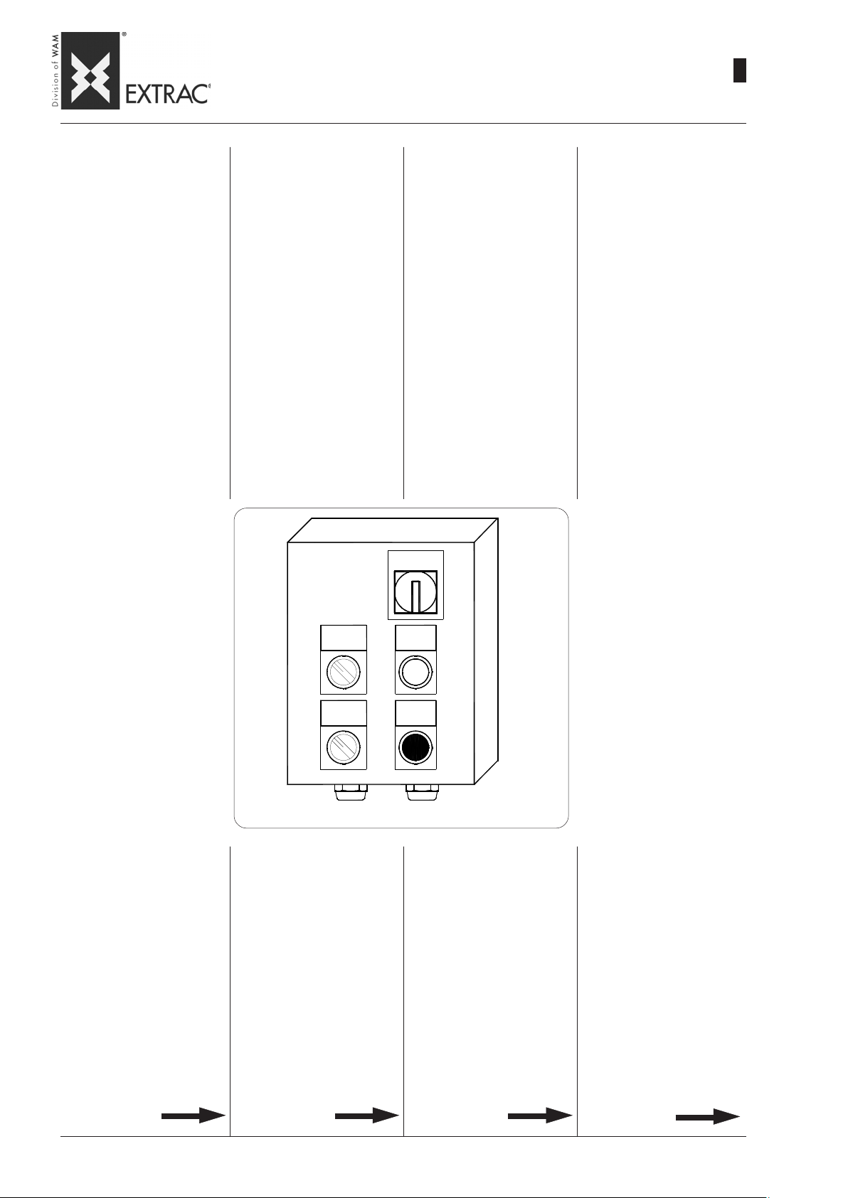
SBB
-
START-UP - PNEUMATIC ACTUATORS
-
INBETRIEBNAHME - PNEUMATISCHE AUSTRAGHILFEN
-
MISE EN SERVICE - ACTIONNEURS PNEUMA TIQUES
-
MESSA IN SERVIZIO - ATTIVATORI PNEUMATICI
09.07
WA.14 M.
2
35
Before starting up the plant, it is
necessary to carry out a series
of checks in order to prevent
problems or risks.
Make sure that all the equipment
components are positioned and
fitted properly.
Carefully check all the electric
and pneumatic connections.
OPERATION
The work cycle can be:
- automatic
- manual.
The cylinders may operate:
- in pairs (the two pneumatic
hammers move in parallel towards the FIBC).
- In single mode (the two pneumatic hammers move alternately).
Vor Inbetriebnahme des Systems muß eine Reihe von Prüfungen vorgenommen werden,
um Probleme oder Risiken zu
vermeiden.
Sicherstellen, daß alle Bestandteile der Vorrichtung korrekt
aufgestellt und befestigt wurden. Alle elektrischen und pneumatischen Anschlüsse sorgfältig prüfen.
FUNKTIONSWEISE
Der Betriebszyklus kann wie
folgt ablaufen:
- automatisch
- von Hand.
Der Betrieb der Zylinder erfolgt:
- gleichzeitig (die beiden Betätigungsstangen fahren parallel
zum BIG-BAG vorwärts)
- abwechselnd (die beiden Betätigungsstangen fahren abwechselnd vorwärts).
Avant de mettre en marche l’installation il est important d’effectuer une série de contrôles afin
de prévenir les problèmes ou les
risques.
S’assurer que tous les composants de la machine sont placés de la bonne manière et
fixés correctement.
Vérifier soigneusement tous les
raccordements électriques et
pneumatiques.
FONCTIONNEMENT
Le cycle de fonctionnement peut
être:
- automatique
- manuel
En outre il est prévu que les
cylindres fonctionnement de
manière:
- simultanée (les deux percuteurs avancent parallèles vers
le BIG-BAF).
- alternée (les deux percuteurs
avancent alternativement).
Prima di effettuare l’ avviamento dell’ impianto è importante che
vengano eseguiti una serie di
controlli al fine di prevenire problemi o rischi.
Accertarsi che tutti i componenti
della macchina siano collocati in
modo opportuno e correttamente fissati.
Verificare accuratamente tutti gli
allacciamenti elettrici e pneumatici.
FUNZIONAMENTO
Il ciclo di funzionamento può
essere:
- automatico
- manuale.
Inoltre è previsto un funzionamento dei cilindri:
- simultaneo (i due percussori
avanzano in parallelo verso il
BIG-BAG).
- alternato (i due percussori
avanzano alternativamente)
A - AUTOMATIC - SINGLE operation
- Turn on the main switch QS to
power the panels (electric and
pneumatic).
- Open the compressed air on/
off valve (to be provided by the
Customer) to supply the electric panel.
- Turn selector SA2 to the "AUTOMA TIC" position.
- Turn selector SA1 to the "SINGLE" position.
- Set the operating times on timers KT1-KT2-KT3.
SA2
SA1
PG21
A - Betrieb AUTOMATISCH ABWECHSELND
- Den Hauptschalter QS drehen,
um die Schalttafeln (elektrisch
und pneumatisch) spannungsführend zu machen.
- Das Sperrventil der Druckluft
(Installation auf Veranlassung
des Kunden) zum Speisen der
elektrischen Schalttafel öffnen.
- Den Wahlschalter SA2 auf die
Stellung "AUTOMA TIK" drehen.
- Den Wahlschalter SA1 auf die
Stellung "SINGLE" drehen.
- Auf den Zeitschaltern KT1KT2-KT3 die Betriebszeiten
einstellen.
Q S
SB
EM
PG16
A - Fonctionnement AUTOMATIQUE - AL TERNÉ
- Tourner l'interrupteur général
QS pour mettre les armoires
sous tension (électrique et
pneumatique).
- Ouvrir la vanne d'arrêt de l'air
comprimé (installation à la charge du Client) pour alimenter l'armoire électrique.
- Tourner le sélecteur SA2 sur la
position "AUTOMATIQUE".
- Tourner le sélecteur SA1 sur la
position "SINGLE".
- Programmer les temps de fonctionnement sur les temporisateurs KT1-KT2-KT3
A - Funzionamento AUTOMATICO - ALTERNATO
- Ruotare interruttore generale
QS per dare tensione ai quadri
(elettrico e pneumatico).
- Aprire la valvola di intercettazione aria compressa (installazione a carico del Cliente)
per alimentare il quadro elettrico.
- Ruotare il selettore SA2 in posizione “AUTOMA TICO”.
- Ruotare il selettore SA1 in posizione “SINGLE”.
- Impostare i tempi di funzionamento sui timer KT1-KT2-KT3.
Page 84

SBB
-
START-UP - PNEUMATIC ACTUATORS
-
INBETRIEBNAHME - PNEUMATISCHE AUSTRAGHILFEN
-
MISE EN SERVICE - ACTIONNEURS PNEUMA TIQUES
-
MESSA IN SERVIZIO - ATTIVATORI PNEUMATICI
09.07
WA.14 M.
2
36
- Press the cycle start pushbutton SB (the automatic cycle
relay KA0 is energized - solenoid valve YV1 is energized and
it pushes activator 1 regulated
by timer KT1 forward.
- At the end of the time set on
timer KT1, solenoid valve YV2
is energized which pushes
activator 2 regulated by timer
KT2 forward and at the same
time activator 1 is drawn back.
- At the end of the time set on
timer KT2, activator 2 is drawn
back and at the same time energizes relay KA1 which holds
the two activators in pause in
the retracted position.
The pause time is regulated by
timer KT3 which, at the end of
the set time, allows the next
cycle to be started up.
- When the FIBC is completely
empty, select push-button EM
to stop the working of the system.
- Die Starte Zyklus-Start SB drücken (das Relais Zyklus Automatik KA0 zieht an - das Magnetventil YV1 wird erregt, das
den Trieb 1, der vom Timer KT1
aktiviert wird, vorwärts
schiebt.
- Nach Ablauf der auf Zeitschalter KT1 eingestellten Zeit erregt
sich das Magnetventil YV2, das
den Trieb 2, der vom Timer KT2
aktiviert wird, vorwärts
schiebt, wobei der Trieb 1 sich
gleichzeitig rückwärts bewegt.
- Nach Ablauf der auf Zeitschalter KT2 eingestellten Zeit bewegt sich der Trieb 2
rückwärts und gleichzeitig
zieht das Relais KA1 an, das
die beiden Triebe in der zurückgefahrenen Position in der Pause hält.
Die Pausenzeit wird vom Zeitschalter KT3 geregelt, der nach
Ablauf der Zeit die Wiederaufnahme des anschließenden
Zyklus gestattet.
- Nach dem Entleeren des BigBag die Taste EM wählen, um
den Betrieb des Systems zu
stoppen.
- Appuyer sur le bouton de marche cycle SB (excitation du
relais de cycle automatique
KA0 - excitation de l'électrovanne YV1 qui pousse vers
l'avant l'activateur 1 réglé par
le temporisateur KT1).
- Quand le temps programmé sur
le temporisateur KT1 est terminé, l'électrovanne YV2 s'excite et pousse vers l'avant l'activateur 2 réglé par le temporisateur KT2 et simultanément
l'activateur 1 recule.
- Quand le temps programmé sur
le temporisateur KT2 est terminé, l'activateur 2 recule et simultanément s'excite le relais
KA1 qui tient en pause les deux
activateurs dans la position
rentrée.
Le temps d'arrêt est réglé par
le temporisateur KT3 qui à la
fin du temps permet la reprise
du cycle successif.
- Quand le vidage du Big-Bag est
terminé, appuyer sur le bouton
EM pour arrêter le fonctionnement du système.
- Premere il pulsante di marcia
ciclo SB (si eccita il relè di ciclo
automatico KA0 - si eccita
l’elettrovalvola YV1 che spinge in avanti l’attivatore 1 regolato dal timer KT1.
- Scaduto il tempo impostato sul
timer KT1 si eccita l’elettrovalvola YV2 che spinge in avanti
l’attivatore 2 regolato dal timer
KT2 e contemporaneamente
retrocede l’attivatore 1.
- Scaduto il tempo del timer KT2
l’attivatore 2 retrocede e contemporaneamente si eccita il
relè KA1 che tiene in pausa i
due attivatori in posizione retratta.
Il tempo di sosta è regolato dal
timer KT3 che a fine tempo consente la ripresa del ciclo successivo).
- Completato lo svuotamento del
Big - Bag selezionare il pulsante EM per arrestare il funzionamento del sistema.
B - AUTOMATIC - IN PAIRS
operation
- Turn on the main switch QS to
power the panels (electric and
pneumatic).
- Open the compressed air on/
off valve (to be provided by the
Customer) to supply the electric panel.
- Turn selector SA2 to the "AUTOMA TIC" position.
- Turn selector SA1 to the "IN
PAIRS" position.
- Set the operating times on timers KT1-KT2-KT3.
- Press the cycle start pushbutton SB (the automatic cycle relay KA0 is energized - solenoid
valves YV1 and YV2 are energized and simultaneously push
the two pneumatic hammers
for the time set on timer KT1.
- At the end of the time set on
timer KT1, both pneumatic hammers are retracted and remain
in pause for the time set on timer KT3.
- When the FIBC is completely
empty, select push-button EM
to stop the operation of the
system.
B - Betrieb AUTOMATISCH SIMULTAN
- Den Hauptschalter QS drehen,
um die (elektrische und pneumatische) Schalttafel spannungsführend zu machen.
- Das Sperrventil der Druckluft
öffnen (Installation durch den
Kunden), um die elektrische
Schalttafel zu speisen.
- Den Wahlschalter SA2 auf die
Stellung "AUTOMA TIK" drehen.
- Den Wahlschalter SA1 auf die
Stellung "IN P AIRS" drehen.
- Die Betriebszeiten auf den Zeitschaltern KT1-KT3 einstellen.
- Die Taste Zyklus Start SB drücken (das Relais Zyklus Automatik KA0 zieht an - die Magnetventile YV1 und YV2 erregen sich, welche die beiden
Betätigungsstangen für die auf
Zeitschalter KT1 eingestellte
Zeit gleichzeitig nach vorn
schieben.
- Nach Ablauf der auf dem Zeitschalter KT1 eingestellten Zeit
fahren beide Betätigungsstangen zurück und bleiben die auf
Zeitschalter KT3 eingestellte
Zeit in der Pause).
- Nach Ablauf der Entleerung des
Big-Bag die Taste EM wählen,
um den Betrieb des Systems
anzuhalten.
B - Fonctionnement AUTOMATIQUE - SIMULTANÉ
- Tourner l'interrupteur général
QS pour mettre les armoires
sous tension (électrique et
pneumatique).
- Ouvrir la vanne d'arrêt de l'air
comprimé (installation à la charge du Client) pour alimenter l'armoire électrique.
- Tourner le sélecteur SA2 sur la
position "AUTOMATIQUE".
- Tourner le sélecteur SA1 sur la
position "IN PAIRS".
- Programmer les temps de fonctionnement sur les temporisateurs KT1-KT2-KT3.
- Appuyer sur le bouton de marche cycle SB (excitation du relais de cycle automatique KA0
- excitation des électrovannes
YV1 et YV2 qui poussent vers
l'avant simultanément les deux
percuteurs pour la durée programmée sur le temporisateur
KT1).
- Quand le temps programmé sur
le temporisateur KT1 est terminé, les deux percuteurs reculent et restent en pause pendant le temps programmé sur
le temporisateur KT3.
- Quand le vidage du Big-Bag est
terminé, appuyer sur le bouton
EM pour arrêter le fonctionnement du système.
B - Funzionamento AUTOMATICO - SIMULTANEO
- Ruotare interruttore generale
QS per dare tensione ai quadri
(elettrico e pneumatico).
- Aprire la valvola di intercettazione aria compressa (installazione a carico del Cliente)
per alimentare il quadro elettrico.
- Ruotare il selettore SA2 in posizione “AUTOMA TICO”.
- Ruotare il selettore SA1 in posizione “IN PAIRS”.
- Impostare i tempi di funzionamento sui timer KT1-KT3.
- Premere il pulsante di marcia
ciclo SB (si eccita il relè di ciclo
automatico KA0 - si eccitano le
elettrovalvola YV1 e YV2 che
spingeranno in avanti contemporaneamente i due percussori
per il tempo impostato sul timer
KT1.
- Scaduto il tempo impostato sul
timer KT1 retrocedono ambedue i percussori restando in
pausa per il tempo impostato
sul timer KT3).
- Completato lo svuotamento del
Big - Bag selezionare il pulsante EM per arrestare il funzionamento del sistema.
Page 85

SBB
-
START-UP - PNEUMATIC ACTUATORS
-
INBETRIEBNAHME - PNEUMATISCHE AUSTRAGHILFEN
-
MISE EN SERVICE - ACTIONNEURS PNEUMA TIQUES
-
MESSA IN SERVIZIO - ATTIVATORI PNEUMATICI
09.07
WA.14 M.
2
37
C - MANUAL - IN PAIRS operation
- Turn on the main switch QS to
power the panels (electric and
pneumatic).
- Open the compressed air on/
off valve (to be provided by the
Customer) to supply the electric panel.
- Turn selector SA2 to the "MANUAL" position.
- Turn selector SA1 to the "IN
PAIRS" position.
- Press the cycle start pushbutton SB. The system works as
long as the start pushbutton is
kept pressed.
D - MANUAL - SINGLE operation
- Turn on the main switch QS to
power the panels (electric and
pneumatic).
- Open the compressed air on/
off valve (to be provided by the
Customer) to supply the electric panel.
- Turn selector SA2 to the "MANUAL" position.
- Turn selector SA1 to the "SINGLE" position.
- Press the start pushbutton SB.
The system works as long as
the start pushbutton is kept
pressed.
C - Betrieb VON HAND - SIMULTAN
- Den Hauptschalter QS drehen,
um den (elektrischen und pneumatischen) Schaltkasten spannungsführend zu machen.
- Das Sperrventil der Druckluft
öffnen (Installation durch den
Kunden), um die elektrische
Schalttafel zu speisen.
- Den Wahlschalter SA2 auf die
Stellung "VON HAND" drehen.
- Den Wahlschalter SA1 auf die
Stellung "SIMUL T AN" drehen.
- Die Start-Taste SB drücken. Das
System funktioniert, solange
man die Start-Taste gedrückt
hält.
D - Betrieb VON HAND - ABWECHSELND
- Den Hauptschalter QS drehen,
um den (elektrischen und pneumatischen) Schaltkasten spannungsführend zu machen.
- Das Sperrventil der Druckluft
öffnen (Installation durch den
Kunden), um die elektrische
Schalttafel zu speisen.
- Den Wahlschalter SA2 auf die
Stellung "VON HAND" drehen.
- Den Wahlschalter SA1 auf die
Stellung "ABWECHSELND" drehen.
- Die Start-Taste SB drücken. Das
System funktioniert, solange
man die Start-Taste gedrückt
hält.
C - Fonctionnement MANUEL
- SIMULTANÉ
- Tourner l'interrupteur général
QS pour mettre les armoires
sous tension (électrique et
pneumatique).
- Ouvrir la vanne d'arrêt de l'air
comprimé (installation à la charge du Client) pour alimenter l'armoire électrique.
- Tourner le sélecteur SA2 sur la
position "MANUEL".
- Tourner le sélecteur SA1 sur la
position "SIMUL TANÉ".
- Appuyer sur le bouton de marche SB. Le système fonctionne tant que le bouton de marche est maintenu enfoncé.
D - Fonctionnement MANUEL
- AL TERNÉ
- Tourner l'interrupteur général
QS pour mettre les armoires
sous tension (électrique et
pneumatique).
- Ouvrir la vanne d'arrêt de l'air
comprimé (installation à la charge du Client) pour alimenter l'armoire électrique.
- Tourner le sélecteur SA2 sur la
position "MANUEL".
- Tourner le sélecteur SA1 sur la
position "ALTERNÉ".
- Appuyer sur le bouton de marche SB. Le système fonctionne tant que le bouton de marche est maintenu enfoncé.
C - Funzionamento MANUALE - SIMULTANEO
- Ruotare interruttore generale
QS per dare tensione ai quadri
(elettrico e pneumatico).
- Aprire la valvola di intercettazione aria compressa (installazione a carico del Cliente)
per alimentare il quadro elettrico.
- Ruotare il selettore SA2 in posizione “MANUALE”.
- Ruotare il selettore SA1 in posizione “SIMULT ANEO”.
- Premere il pulsante di marcia
SB. Il sistema funziona finché
si tiene premuto il pulsante di
marcia.
D - Funzionamento MANUALE - ALTERNAT O
- Ruotare interruttore generale
QS per dare tensione ai quadri
(elettrico e pneumatico).
- Aprire la valvola di intercettazione aria compressa (installazione a carico del Cliente)
per alimentare il quadro elettrico.
- Ruotare il selettore SA2 in posizione “MANUALE”.
- Ruotare il selettore SA1 in posizione “ALTERNATO”.
- Premere il pulsante di marcia
SB. Il sistema funziona finché
si tiene premuto il pulsante di
marcia.
CHECKS MADE AT THE FACTORY
The equipment has been subjected to actual operating tests
load-free for about 15 minutes
at the factory, so as to guarantee correct start-up.
VOM HERSTELLER DURCHGEFÜHRTE KONTROLLEN
Die Vorrichtung wurde im Herstellerwerk einer abschließenden Funktionskontrolle unterzogen der leeren Vorrichtung auf
die Dauer von ca. 15 Minuten.,
um eine korrekte Inbetriebnahme zu garantieren.
CONTRÔLES EFFECTUÉS
DANS NOS ETABLISSEMENTS
Cette machine a été soumise,
dans l’ établissement du constructeur un fonctionnement à
vide pendant environ 15 minutes, à un essai fonctionnel de
réception afin de garantir une
mise en service correcte.
CONTROLLI EFFETTUATI NEI
NOSTRI STABILIMENTI
La macchina ha subito, presso
gli stabilimenti del costruttore, un
reale collaudo funzionale a vuoto per circa 15 minuti così da
garantire la corretta messa in
esercizio.
Page 86

SBB
-
MAINTENANCE - WARNING
-
WARTUNG - HINWEISE
-
ENTRETIEN - RECOMMANDATIONS
-
MANUTENZIONE - A VVERTENZE
09.07
WA.14 M.
2
38
MAINTENANCE
Before carrying out any operation,
make sure the machine is in safety condition
In this manual, from here onwards
“setting the machine in safety
conditions” will indicate the following operations:
- Make sure the machine is disconnected from all electric power supply sources.
- Make sure the machine is completely stopped.
- Wait for the internal and external machine temperatures to
reach values not dangerous to
the touch.
- Provide sufficient lighting
around the machine operating
area (the operators may be provided with electric lamps with
protection degree IP65, if necessary).
- Make sure the machine is disconnected from the compressed
air supply.
- Wait for the powder mass inside
the silo to settle down completely.
Before carrying out any operation
on the machine (maintenance or
cleaning), the operators must use
suitable personal protection
equipment:
- antistatic safety footwear (certified)
- antistatic protective clothing (certified)
- helmet
- antistatic, cut-proof gloves
- safety masks
WARTUNG
Vor Eingriffen jeder Art am Gerät
überprüfen, ob dieses in einen
sicheren Zustand versetzt wurde.
In diesem Handbuch verstehen
wir unter dem Begriff „das Gerät
in einen sicheren Zustand bringen” die folgenden Maßnahmen:
- Sicherstellen, dass die Maschine von allen elektrischen Versorgungsquellen getrennt ist.
- Sicherstellen, dass alle beweglichen Geräteteile still stehen.
- Sicherstellen, dass die Innenund Außentemperatur des
Gerä-tes einen Wert erreicht hat,
der bei Berührung ungefährlich
ist.
- Dafür sorgen, dass der Bereich
rings um das Gerät gut be-leuchtet ist (eventuell indem man das
Personal mit elektrischen Lampen mit Schutzart IP65 ausstattet).
- Sicherstellen, dass das Gerät
vom Versorgungsnetz für Druckluft abgetrennt ist.
- Abwarten, bis der Staub, der sich
innerhalb des Gerätes befindet,
sich vollkommen abgesetzt hat.
Für jede Arbeit, die am Gerät auszuführen ist, (Wartung und Reinigung) muss das Personal mit den
entsprechenden persönlichen
Schutzausrüstungen (PSA) ausgestattet sein:
- Antistatische Sicherheitsschuhe
(zertifiziert)
- Antistatische Schutzkleidung
(zertifiziert)
- Schutzhelme
- Antistatische Schnittschutzhandschuhe
- Atemschutzmasken.
ENTRETIEN
Avant d’effectuer une quelconque
intervention sur la machine s’assurer que celle-ci a été placée en
condition de sécurité.
Dans le présent manuel la consigne “mettre la machine en sécurité” indique les opérations suivantes :
- S’assurer que la machine est
débranchée de toutes les alimentations électriques;
- S’assurer que la machine est
complètement arrêtée;
- Attendre que la température intérieure et extérieure de la machine a atteint une valeur qui
n’est pas dangereuse au toucher;
- Eclairer correctement la zone
qui entoure la machine (en dotant éventuellement les opérateur de lampes électriques avec
degré de protection IP65);
- S’assurer que la machine est
débranchée du réseau de distribution de l’air comprimé;
- Attendre que la poussière contenue à l’intérieur de la machine se soit entièrement déposée.
Pour toute opération à effectuer
sur la machine (entretien et nettoyage), les opérateurs devront
être munis des équipements de
protection individuelle (EPI) :
- Chaussures de sécurité antistatiques (certifiées)
- Vêtements de protection antistatiques (certifiés)
- Casque
- Gants anticoupure antistatiques
- Maques de protection respiratoire
MANUTENZIONE
Prima di effettuare un qualsiasi
intervento sulla macchina assicurarsi che questa sia messa in sicurezza.
In seguito nel presente manuale
indicheremo con la dicitura “mettere in sicurezza la macchina” le
seguenti operazioni:
- accertarsi che la macchina sia
scollegata da tutte le alimentazioni elettriche;
- accertarsi che la macchina sia
completamente ferma;
- attendere che la temperatura
interna ed esterna della macchina abbia raggiunto un valore non pericoloso al tatto;
- provvedere ad illuminare correttamente la zona circostante alla
macchina (eventualmente dotando gli operatori di lampade
elettriche con grado di protezione IP65);
- accertarsi che la macchina sia
scollegata dalla rete di distribuzione d’aria compressa;
- attendere che la polvere contenuta all’interno della macchina
sia completamente depositata.
Per qualsiasi operazione da effettuarsi sulla macchina (manutenzioni e pulizia), gli operatori
dovranno essere muniti degli appositi dispositivi di protezione individuale (DPI):
- scarpe antinfortunistiche antistatiche (certificate)
- indumenti protettivi antistatici
(certificati)
- casco
- guanti antitaglio antistatici
- mascherine protettive
In addition to these, use the safety devices specified in the safety
chart of the product handled.
Machine operations must be
carried out with the machine in
safety conditions disconnected
from all energy sources and in
the absence of airborne dust;
follow the machine stop procedure for maintenance.
All maintenance operations,
whether ordinary or extraordinary,
must be carried out by adopting
the suitable personal protection
equipment required and by following the instructions in this
manual strictly.
To reach the parts at the top of
the machine, use a work platform,
which must be chosen in such a
way as to prevent risk of slipping,
tripping or falling of operators.
Außerdem auch die Schutzvorrichtungen, die auf dem Sicherheitsdatenblatt zu filternden Produkts stehen.
Die Wartungsarbeiten müssen
bei in den sicheren Zustand gebrachter Maschine ausgeführt
werden, wenn diese von allen
Energiequellen getrennt ist, und
in Abwesenheit von durch die
Luft verteiltem Staub: Die ganze
Prozedur zum Anhalten der Maschine durchführen, bevor man
mit der Wartung beginnt.
Alle Wartungsarbeiten, sowohl
regelmäßige als auch außerordentliche, müssen unter Anwendung aller erforderlichen persönlichen Schutzeinrichtu ngen und
unter Beachtung aller Angaben
dieses Handbuchs ausgeführt werden.
Wenn Teile der Maschine erreicht
werden müssen, die sich in größerer Höhe befinden, benutzen
Sie eine Arbeitsbühne, die so zu
wählen ist, dass Ausrutsch-, Stolper- und Abstürzgefahren für das
Personal vermieden werden.
En outre les équipements de protection prévus par la fiche de sécurité du produit filtré.
Les opérations d’entretien doivent être effectuées avec la
machine en condition de sécurité, débranché de toute source
d’énergie et en absence de
poussières dispersée dans l’air
: effectuer toute la procédure d’arrêt de la machine avant de commencer l’entretien.
Toutes les opérations d’entretien,
aussi bien ordinaire qu’extraordinaire, doivent être exécutées en
adoptant tous les dispositifs de
protection individuelle requis et
en suivant attentivement les indications de cette notice.
Si l’on doit atteindre des parties
de la machine, utiliser une plateforme aérienne de travail qui devra être choisie de manière à éviter les dangers de glissement,
heurt ou chute des opérateurs.
Inoltre occorre utilizzare tutti i dispositivi di protezione previsti
dalla scheda di sicurezza del prodotto filtrato.
Le operazioni di manutenzione
devono essere effettuate a macchina in sicurezza, scollegata
da ogni fonte di energia e in assenza di polvere aerodispersa:
seguire tutta la procedura di arresto della macchina prima di
iniziare la manutenzione.
Tutte le operazioni di manutenzione, sia ordinaria che straordinaria, devono essere eseguite
adottando tutti i dispositivi di protezione personale richiesti e seguendo attentamente le indicazioni di questo manuale.
Laddove si debbano raggiungere parti della macchina in quota,
utilizzare una piattaforma aerea
di lavoro che dovrà essere scelta
in modo da evitare pericoli di scivolamento, inciampo o caduta per
gli operatori.
Page 87

SBB
-
MAINTENANCE - WARNING
-
WARTUNG - HINWEISE
-
ENTRETIEN - RECOMMANDATIONS
-
MANUTENZIONE - A VVERTENZE
09.07
WA.14 M.
2
39
The machine can be used with a
very large range of products; this
involves different degrees of wear
on some components.
The recommended maintenance
schedules are therefore subject to
modifications.
It is always preferable to program
maintenance operations periodically instead of having to act in
emergency conditions so as to
eliminate potential stops during
periods of peak production.
Failure to follow the instruc-tions
given below can lead to risks
for the operators and lead to invalidation of the warranty on the
equipment supplied.
CAUTION
All maintenance, lubrication and
cleaning operations must be performed with the machine in safety conditions.
For hazardous materials, suitable
PPD (personal protection devices) must be used in accordance
with the safety chart of the powder handled.
Das Gerät kann für unter-schiedliche Medien eingesetzt werden,
was einen unterschiedlich schnellen Verschleiß einiger Komponenten zur Folge haben kann.
Die empfohlenen Wartungsabstände können daher Änderungen
unterliegen.
Es ist immer besser, regelmäßige
Wartungseingriffe zu planen, statt
erst im Notfall eingreifen zu müssen, weil dann die Gefahr etwaiger Ausfallzeiten nicht besteht,
wenn max. Produktionsauslastung
vorgesehen ist.
Die Nichtbeachtung der folgenden Anweisungen kann zur Gefährdung des Personals und zum
Ungültigwerden der Garantie auf
die gelieferten Maschinen führen.
ACHTUNG
Vor der Ausführung von Wartung, Schmierung oder Reinigungsarbeiten ist die Maschine
in den sicheren Zustand zu bringen.
Für gefährliches Schüttgut sind
die persönlichen Schutzausrüstungen zu benutzen, die auf den
Sicherheitsdatenblättern des behandelten Schüttguts beschrieben sind.
Il est rappelé que la machine
peut travailler avec une très vaste gamme de produits et ceci
comporte une rapidité différente
dans l’usure de certains composants.
Le calendrier des intervention
d’entretien est donc susceptible
de variations.
Il convient de programmer régulièrement les interventions au lieu
d’intervenir en conditions d’émergence, afin d’éliminer les arrêts
potentiels pendant les périodes
de production maximale.
L’ inobservation des consignes
suivantes peut provoquer des
risques pour les opérateurs et
invalider la garantie des machines fournies.
ATTENTION
Toute intervention d’entretien,
lubrification et nettoyage doit
être exécutée la machine en
condition de sécurité.
Pour les matières dangereuses il
faut utiliser les EPI appropriés
conformément à la fiche de sécurité de la poudre traitée.
Si ricorda che la macchina può
lavorare con una vastissima gamma di prodotti, e ciò comporta
una diversa rapidità nell’ usura di
alcuni componenti.
I tempi di intervento di manutenzione consigliati sono quindi suscettibili di modifiche.
E‘ sempre preferibile programmare periodicamente gli interventi
anziché dover intervenire in condizioni di emergenza così da eliminare potenziali arresti durante
i periodi di massima produzione.
Il non attenersi strettamente alle
seguenti istruzioni può causare
rischi sugli operatori ed invalidare la garanzia sulle macchine fornite.
ATTENZIONE
Ogni intervento di manutenzione, lubrificazione e pulizia deve
essere eseguito a macchina in
sicurezza.
Per materiali pericolosi si devono usare i DPI idonei in accordo
con la scheda di sicurezza della
polvere trattata.
Maintenance must be done only
by qualified technicians.
Lift and handle all heavy parts
using suitable lifting equipment.
Make sure that the parts or components are supported by suitable harnesses or hooks.
Ensure that there is no one standing in the area where the load is
being lifted.
Remember that careful periodic
maintenance and correct use are
essential requirements for guaranteeing high machine performance.
To ensure that the machine functions constantly and normally and
to prevent the guarantee's replacement clauses being invalidated, we recommend that you
always use original spare parts.
Maintenance of the vibrator motor must be carried out in accordance with the instructions given
in the relevant manual.
Die Wartungsarbeiten sind von
spezialisierten Technikern auszuführen.
Alle schweren Einzelteile mit einer angemessenen Hubeinrichtung heben und transportieren.
Sicherstellen, daß Gruppen oder
Einzelteile von passenden Anschlagelementen und Haken gehalten werden.
Sicherstellen, daß sich in der
Nähe der zu hebenden Maschine
keine Personen aufhalten.
Eine genaue und regelmäßige
Wartung wie auch eine korrekte
Benutzung sind in der Regel die
Voraussetzungen für eine hohe
Leistung der Maschine.
Um einen konstanten und ordnungsgemäßen Betrieb zu garantieren und zu vermeiden, die Voraussetzungen für die Garantiegewähr zu verlieren, sollte man
immer nur Originalersatzteile verwenden.
Die Wartung des Unwuchtmotors
ist gemäß der Angaben im Handbuch desselben vorzunehmen.
Les opérations d’ entretien doivent être effectuées par des techniciens spécialisés.
Soulever et manipuler les pièces
lourdes avec un moyen de levage approprié.
S’ assurer que les groupes ou les
pièces sont soutenues par des élingues et des crochets appropriés.
S’ assurer qu’ il n’ y a personne à
proximité de la charge à soulever.
Il est rappelé qu’ un entretien régulier et précis ainsi qu’une utilisation correcte sont les conditions
indispensables pour garantir un
rendement élevé de la machine.
Pour assurer un fonctionnement
constant, régulier et ne pas risquer de ne plus bénéficier du remplacement sous garantie, il est
recommandé d’utiliser uniquement des pièces détachées d’origine.
L’entretien du motovibrateur doit
être réalisé en suivant les indications contenues dans le manuel.
tuellement branché à la RSM).
Le operazioni di manutenzione
devono essere effettuate da tecnici specializzati.
Sollevare e maneggiare tutti i
particolari pesanti con un mezzo
di sollevamento adatto.
Assicurarsi che i gruppi od i particolari siano sostenuti da imbragature e ganci appropriati.
Accertarsi che non ci siano persone in prossimità del carico da sollevare.
Si ricorda che una precisa e periodica manutenzione ed un uso
corretto sono la premessa indispensabile per garantire un elevato rendimento della macchina.
Per assicurare il suo costante e
regolare funzionamento ed evitare che vengano a mancare i presupposti per la sostituzione in
garanzia, si raccomanda di utilizzare sempre ricambi originali.
La manutenzione del motovibratore deve essere eseguita secondo le indicazioni contenute nel
manuale dello stesso.
Page 88

SBB
-
MAINTENANCE
-
WARTUNG
-
ENTRETIEN
-
MANUTENZIONE
09.07
WA.14 M.
2
40
PERIODIC CHECKS
Before every work shift
Check the safety devices to ensure they are present and intact.
After every work shift
Make sure that the passage of
the material is free of residue; if
this is not the case, clean carefully.
Every 100 hours of operation
(every 2 weeks)
Check the condition of the FIBC
support seal.
Every 200 hours of operation
(monthly)
1 - Check the appearance of the
structure, paying particular attention to the state of:
- welds in general;
- motovibrator fixing plate;
- damper support plates.
REGELMÄSSIGE KONTROLLEN
Vor jeder Schicht
Sicherstellen, daß die Schutzvorrichtungen vorhanden und
unversehrt sind.
Nach jeder Schicht
Sicherstellen, daß der Produktdurchlaufbereich keine Produktreste aufweist; an-dernfalls
ist dieser Bereich sorgfältig zu
reinigen.
Alle 100 Betriebsstunden
(alle 2 Wochen)
Den Zustand der Dichtungen
prüfen, auf denen der Sack aufliegt.
Alle 200 Betriebsstunden
(monatlich)
1 - Das Aussehen der Struktur
prüfen, wobei besonders auf
folgendes zu achten ist:
- Schweißstellen im allgemeinen;
- Befestigungsplatte des Vibrationsmotors;
- Trageplatten der Schwingungsdämpfer.
CONTRÔLES PÉRIODIQUES
Avant chaque poste de travail
Vérifier la présence et l’intégrité
des protections.
Après chaque poste de travail
Vérifier que la zone de passage
du produit est libre de tous résidus; dans le cas contraire nettoyer soigneusement
Toutes les 100 heures de travail (tous les 15 jours)
Contrôler l’état du joint d’appui
du Big Bag.
Toutes les 200 heures de travail (tous les mois)
1 - Vérifier l’ aspect de la struc-
ture du fond en faisant attention à:
- points de soudures;
- plaque de fixation du moto-vibrateur;
- plaques de soutien des dispositifs anti-vibration.
CONTROLLI PERIODICI
Prima di ogni turno di lavoro
Verificare la presenza e l’integrità delle protezioni.
Dopo ogni turno di lavoro
Verificare che la zona di passaggio del materiale sia libera da
residui dello stesso ; se non lo è
pulire accuratamente
Ogni 100 ore di lavoro
(ogni 15 giorni)
Controllare lo stato di efficienza
della guarnizione di appoggio Big
Bag.
Ogni 200 ore di lavoro
(ogni mese)
1 - Verificare l’ aspetto della strut-
tura prestando attenzione a:
- saldature in genere;
- piastra di fissaggio del motovibratore;
- piastre di sostegno degli antivibranti.
2 - Check that all bolts are cor-
rectly tightened, in par-ticular the motovibrator fixing
bolts.
3 - Check the seal for cracks or
splits.
4 - Check the dampers for signs
of collapse (load deformation
must not exceed 10% of nominal height).
5 - Check that the motovi-brator
is as clean as pos-sible.
6 - Check the seals of the com-
pressed air connections.
7 - Check to make sure the pneu-
matic cylinders of the pneumatic actuators kit (if
present) are in perfect working order.
2 - Kontrolle der Schrauben auf
festen Sitz, insbesondere der
Schrauben zur Befestigung
des Vibrations-motors.
3 - Sicherstellen, daß die Dich-
tungen keine Risse oder
Bruchstellen aufweisen.
4- Sicherstellen, daß die
Schwingungsdämpfer nicht
verformt sind (die Verformung unter Lasteinwirkung
darf nicht mehr als 10% über
der Nennhöhe liegen).
5 - Sicherstellen, daß der Vibra-
tionsmotor so sauber wie
möglich ist.
6 - Die pneumatischen Anschlüs-
se auf dichten Sitz prüfen.
7- Die Funktionstüchtigkeit der
pneumatischen Zylinder des
Bausatzes pneumatische
Austraghilfen prüfen (falls
vorhanden).
2- Contrôler si les boulons ont
été serrés correctement en
faisant particulièrement attention à ceux qui fixent le motovibrateur.
3 -Contrôler que les joint ne pré-
sent aucune fissure ou lacération.
4- Contrôler que les dispositifs
anti-vibration ne sont pas défoncés (la déformation ne doit
pas dépasser 10% de la
hauteur nominale).
5- Contrôler que le moto-vibra-
teur est toujours très propre.
6- Contrôler la tenue des rac-
cordements pneumatiques.
7- Contrôler l’efficacité des cy-
lindres pneumatiques du kit
des actionneurs pneumatiques (si prévu)
2 - Controllare il corretto serrag-
gio dei bulloni prestando particolare attenzione a quelli di
fissaggio del motovibratore.
3 - Controllare che non ci siano
screpolature o fessurazioni
nella guarnizione.
4 - Controllare che gli antivibran-
ti non presentino segni di
sfondamento (la deformazione sotto carico non deve superare il 10% dell’ altezza
nominale).
5 - Controllare che il motovibra-
tore sia il più pulito possibile.
6 - Controllare la tenuta dei col-
legamenti pneumatici.
7- Controllare l’ efficienza dei ci-
lindri pneumatici del kit attivatori pneumatici (se presente)
Page 89

SBB
-
CLEANING
-
REINIGUNG
-
NETTOY AGE
-
PULIZIA
09.07
WA.14 M.
2
41
The detergents to be used for
cleaning the various equipment
must have a flash point indicated in the respective safety chart,
higher than the temperature
reached in normal operating conditions and reasonably expected; therefore, there should be
no risk of fire.
Before starting cleaning operations, set the machine in safety
conditions.
When removing dust that may be
present on the machine, take
care to avoid spreading it in the
surrounding area.
The user must provide for the
choice of suitable products for
cleaning, depending on the type
of plant and the product handled.
the FIBC UNLOADERS meant for
use with food products, provision must be made for cleaning
at intervals depending on the
type or product and plant.
In case of harmful products, the
cleaning wastes must be conveyed to a tank and disposed
off according to relevant regulations.
Die für die Reinigung der verschiedenen Geräte zu benutzenden Reinigungsmittel müssen einen Flammpunkt aufweisen (siehe entsprechendes Sicherheitsdatenblatt), der über der Temperatur liegt, die unter normalen
und vorhersehbaren Einsatzbedingungen erreicht wird. Daher
können sie keine Brandgefahr
darstellen.
Bevor man mit der Reinigung beginnt, ist das Gerät in den sicheren Zustand zu versetzen.
Beim Entfernen des Staubs, der
eventuell im Gerät vorhanden ist,
ist darauf zu achten, dass dieser nicht aufgewirbelt wird.
Der Benutzer muss Produkte
auswählen, die für den jeweiligen Typ der Anlage und das behan-delte Schüttgut geeignet
sind.
Für die BIG-BAG Entleerstationen, die für Nahrungsmittel eingesetzt werden soll, ist die Häufigkeit der Reinigung abhängig
von der Beschaffenheit des behandelten Produkts und vom Anlagentyp.
Bei schädlichen oder giftigen
Produkten muss das Spülwasser in geeigneten Wannen aufgefangen und in Übereinstimmung mit den einschlägigen geltenden Bestimmungen entsorgt
werden.
Les détergents à utiliser pour le
nettoyage des différents appareillages doivent présenter un
point d’inflammabilité, reporté sur
les fiches de sécurité correspondantes, supérieur à la température pouvant être atteinte
dans les conditions d’utilisation
normales et raisonnablement
prévisibles; par conséquent ils
ne doivent pas déterminer un risque d’incendie.
Avant de commencer les opérations de nettoyage, mettre la
machine en condition de sécurité.
Lors du nettoyage de la poussière présente dans la machine,
faire attention à ne pas la disperser dans le milieu ambiant.
L’utilisateur devra choisir des
produits appropriés pour le nettoyage en fonction de la typologie d’installation et de la matière
transportée.
Pour les vide BIG-BAG destinés
à être utilisés avec des produits
alimentaires, il faut prévoir une
phase de nettoyage à une fréquence qui dépend de la nature
du produit et de l’installation.
Dans le cas de produits nocifs,
toxiques, les effluents de la phase de nettoyage doivent être
convoyés dans une cuve appropriée et éliminés conformément
à la norme en vigueur en la matière.
I detergenti da impiegare per la
pulizia delle varie apparecchiature devono presentare un punto di infiammabilità, riportato nelle rispettive schede di sicurezza, superiore alla temperatura
raggiungibile nelle condizioni di
utilizzo normali e ragionevolmente prevedibili; pertanto non possono determinare pericoli di incendio.
Prima di iniziare le operazioni di
pulizia mettere in sicurezza la
macchina.
Nella rimozione della polvere
eventualmente presente nella
macchina aver cura di non disperdere la polvere stessa nell’ambiente circostante.
L’utilizzatore dovrà provvedere
alla scelta dei prodotti idonei alle
fasi di pulizia in base alla tipologia di impianto ed al prodotto trasportato.
Per gli svuota BIG-BAG destinati
ad essere utilizzati con prodotti
alimentari occorre prevedere una
fase di pulizia con frequenza che
dipende dalla natura del prodotto e dell’impianto.
Nel caso di prodotti nocivi, tossici, i reflui della fase di pulizia dovranno essere convogliati in idonea vasca e smaltiti in accordo
alle normative vigenti in materia.
Page 90

SBB
-
OPERATION NOISE
-
BETRIEBSGERÄUSCHE
-
BRUY ANCE
-
RUMOROSITÀ
09.07
WA.14 M.
2
42
OPERATION NOISE
The noise level values, expressed in dB(A) are obtained
from readings made in an open
field, at maximum performance,
on 4 cardinal points at a distance
of 1.5 metres from the equipment.
The values obtained are:
max. 75 dB(A)
The user may obtain values different from those indicated depending on the environment in
which the equipment is installed.
It is therefore advisable to avoid
installing the equipment near corners, walls and boxed metal
structures.
The noise values refer to the
machine complete with accessories, if any.
BETRIEBSGERÄUSCHE
Die Werte des Lärmpegels, ausgedrückt in dB(A), resultieren
aus Freifeldmessungen bei maximaler Leistungsstufe, in den 4
Himmelsrichtungen, in 1,5 Meter
Abstand von der Vorrichtung.
Meßwerte:
max. 75 dB(A)
Der Betreiber kann je nach derPositionierung der Vorrichtung im
Raum auf andere Werte treffen.
Daher die Vorrichtung nicht in
Ecken, nahe an Wänden oder
Metallstrukturen aufstellen.
Der Wert des Lärmpegels bezieht sich auf die Maschine mit
eventuellen angebauten Zubehörteilen.
NIVEAU SONORE
Les valeurs du niveau sonore,
exprimées en dB(A) sont obtenues à travers des lectures en
champ libre, au rendement maximum, sur les 4 points cardinaux
à 1,5 mètres de la machine.
Valeurs mesurées:
max. 75 dB(A)
L’ utilisateur pourrait relever des
valeurs différentes de celles indiquées en fonction de l' emplacement de la machine.
Il est préférable d' éviter de placer la machine à proximité des
angles, murs, structures métalliques en caisson.
La valeur de bruit se réfère à la
machine complète avec tout accessoire éventuel.
RUMOROSITÀ
I valori di rumorosità, espressi in
dB (A) sono ottenuti attraverso
letture eseguite in campo libero,
al massimo rendimento, sui 4
punti cardinali a 1,5 metri dalla
macchina.
I valori rilevati sono:
dB(A) max. 75
L’ utilizzatore potrebbe rilevare
valori diversi da quelli indicati in
funzione della collocazione ambientale.
Pertanto è preferibile evitare di
collocare la macchina in prossimità di angoli, pareti, strutture
metalliche cassonate.
Il valore di rumorosità si riferisce
alla macchina completa di eventuali accessori.
Page 91
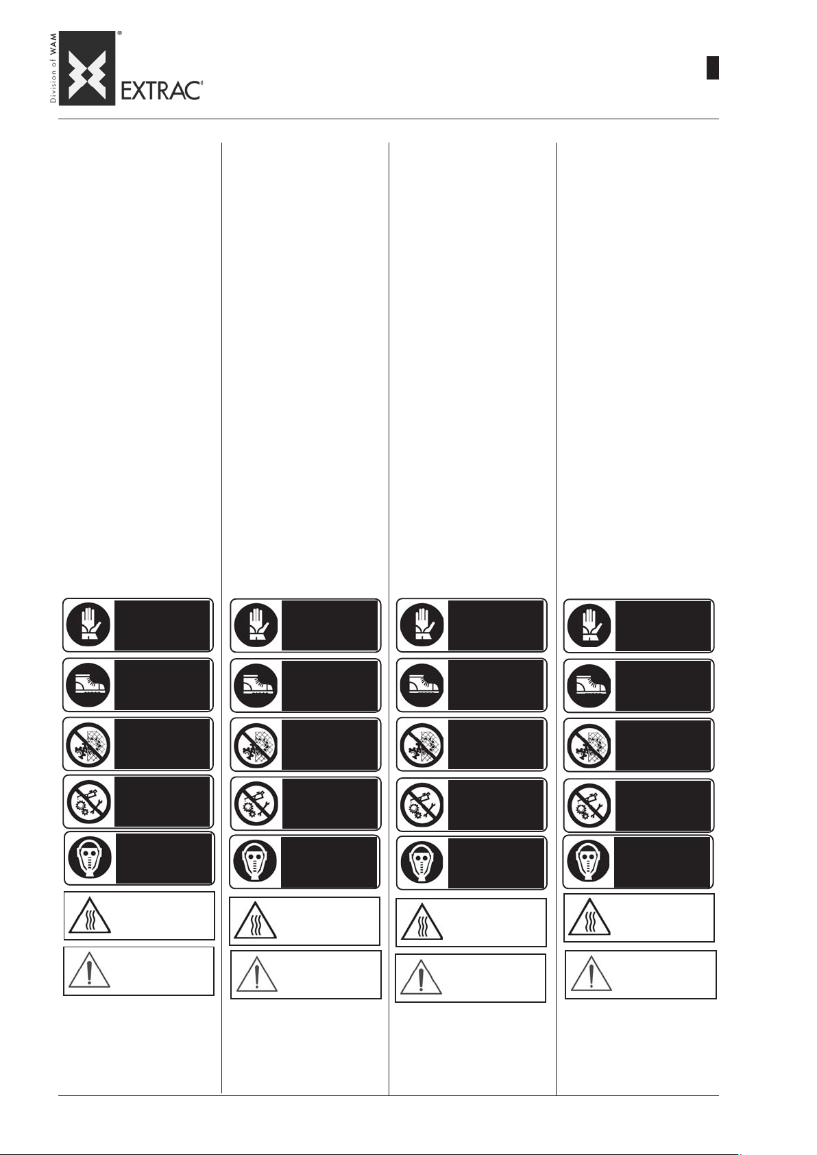
SBB
-
RESIDUAL RISKS
-
RESTRISIKEN
-
RISQUES RESIDUELS
-
RISCHI RESIDUI
09.07
WA.14 M.
2
43
During operations and/or maintenance, the operators ARE NOT
exposed to any residual risks.
In any case, it shall be the
installer’s responsibility to
provide further indications
and/or warning notices
which may be necessary depending on the machine installation site and the material handled.
When servicing, inspecting or
cleaning, the operator, after setting the machine to safety conditions, must use some of the individual protection devices indicated on the additional special
plates to be affixed to the various machine sections.
Given below are examples of
some warning notices which
may be necessary, depending on
the type of powder handled.
Während des Betriebs und der
Wartung ist das Personal KEINEN
Restgefahren ausgesetzt.
Es ist daher auf jeden Fall
Aufgabe des Monteurs, weitere Angaben und /oder
Schilder anzubringen, die in
bezug auf den Einbauort und
das behandelte Schüttgut
erforderlich werden könnten.
Während der Wartungsarbeiten,
der Inspektion und Reinigung
und, nachdem man die Maschine in den sicheren Zustand gebracht hat, ist es auf jeden Fall
erforderlich, dass das Bedienungspersonal einige persönliche Schutzausrüstungen benutzt, so wie durch Warnschilder, die in den einzelnen Bereichen des Geräts hinzuzufügen
sind.
Untenstehend folgen Beispiele
einiger Schilder, die je nach Art
der verarbeiteten Pulver erforderlich sein könnten.
Pendant le travail et/ou l’entretien, les opérateurs ne sont PAS
exposés à certains risques résiduels.
Dans tous le cas, l’installateur devra se charger d’apposer les indications ou les
panneaux de signalisation
qui peuvent s’avérer nécessaires en fonction du lieu
d’installation de la machine
et de la matière traitée.
Pendant les activités de maintenance, inspection et nettoyage
et après avoir mis la machine en
sécurité il est obligatoire que
l’opérateur utilise des équipements de protection individuelle
comme indiqué sur les plaques
signalétiques à ajouter dans les
différentes sections de la machine.
Voir ci-après, à titre d’exemple,
quelques plaques qui pourraient
se rendre nécessaires en fonction du type de poudre traitée.
Durante la lavorazione e/o la
manutenzione, gli operatori NON
sono esposti ad alcuni rischi residui.
In ogni caso sarà cura dell’installatore apporre ulteriori indicazioni e/o cartellonistiche che si potrebbero
rendere necessarie in funzione del luogo di installazione della macchina e del materiale trattato.
Durante le attività di manutenzione, ispezione, pulizia, dopo aver
messo in sicurezza la macchina, è obbligatorio che l’operatore utilizzi alcuni dispositivi di protezione individuale come indicato da apposite targhe monitorie
da aggiungere nelle singole sezioni della macchina.
Di seguito si riportano a titolo
esemplificativo alcune targhe
che potrebbero rendersi necessarie in funzione del tipo di polvere.
COMPULSORY
USE OF GLOVES
COMPULSORY
USE OF SAFETY
FOOTWEAR
FORBIDDEN TO
REMOVE SAFETY
DEVICES
FORBIDDEN TO
REPAIR OR ADJUST
WHILE IN MOTION
COMPULSORY
USE OF A MASK
ATTENTION
DANGEROUSE
TEMPERATURE
HARMFUL
SUBSTANCES
HANDSCHUTZ
BENUTZEN
SICHERHEITSSCHUHWERK
BENUTZEN
DAS ENTFERNEN DER
SICHERHEITSVOR-
RICHTUNGEN IST
VERBOTEN
REPARIEREN ODER
EINSTELLEN BEI
LAUFENDER
MASCHINE IST
VERBOTEN
ATEMSCHUTZ
BENUTZEN
ACHTUNG
GEFÄHRLICHE
TEMPERATUREN
ACHTUNG
SCHADSTOFFE
PORT DE GANTS
OBLIGATOIRE
PORT DE
CHAUSSURES DE
SÉCURITÉ
OBLIGATOIRE
INTERDICTION
D’ENLEVER LES
DISPOSITIFS DE
SÉCURITÉ
INTERDICTION DE
RÉPARER OU DE
RÉGLER PENDANT
LA MARCHE
PORT DU
MASQUE
OBLIGATOIRE
ATTENTION
TEMPÉRATURES
DANGEREUSES
ATTENTION
SUBSTANCE
NOCIVES
E’ OBBLIGATORIO
USARE I GUANTI
E’ OBBLIGAT ORIO
USARE LE
CALZATURE
DI SICUREZZA
VIETATO
RIMUOVERE
I DISPOSITIVI
DI SICUREZZA
VIETATO RIP ARARE O
REGISTRARE
DURANTE IL MOTO
È OBBLIGATORIO
USARE LA
MASCHERA
ATTENZIONE
TEMPERATURE
PERICOLOSE
ATTENZIONE
SOSTANZE
NOCIVE
Page 92

SBB
-
SCRAPPING - RETURNING THE MACHINE
-
VERSCHROTTUNG - MASCHINENRÜCKGABE
-
DEMANTELEMENT - RESTITUTION MACHINE
-
ROTT AMAZIONE - RESO MACCHINA
09.07
WA.14 M.
2
44
Before carrying out any operation, set the machine in safety
status and use suitable personal protection devices.
SCRAPPING
For scrapping the machine at the
end of its life, make sure the plastic parts (seals and components) are collected separately
and sent to special centres for
disposal.
The other parts meant for recycling must be sent to iron scrap
yards.
When dismantling the machine
make sure the lifting procedures
indicated in the HANDLING section (page M.14) are followed.
For disposal of materials contained in the machine, refer to
the existing legislation concerning disposal and the product
safety chart.
Vor Arbeiten jeglicher Aret an
dem Gerät muss dieses in einen
sicheren Zustand versetzt werden und geeignete PSA angelegt
werden.
VERSCHROTTUNG
Bei Verschrottung des Gerätes
sind die Teile aus Kunststoff
(Dichtungen und Komponenten)
auszubauen und vorschriftsmäßig zu entsorgen.
Die restlichen Teile sind beim
Scrotthändler abzugeben.
Während des Zerlegens des
Gerätes die Anleitungen zum
Anheben beachten, die im Teil
HANDLING DES GERÄTES auf
Seite M.14 nachzulesen sind.
Für die Entsorgung des im Gerät
vorhandenen Produkts ist Bezug
auf die geltenden Bestimmungen
zur Materialentsorgung und die
Sicherheitsdatenblätter der Produkte zu nehmen.
Avant toute intervention mettre
la machine en condition de sécurité et utiliser les EPI appropriés.
DEMANTELEMENT
En cas de démantèlement de la
machine, démonter les parties en
matières plastique (joints et composants) et les mettre à la décharge dans les déchetteries
spécialisées.
Les parties restantes sont destinées à la récupération des matériaux ferreux.
Pendant les phases de démantèlement de la machine respecter les procédures de levage
comme indiqué dans la section
MANUTENTION (page M.14)
Pour l’élimination de la matière
contenue dans la machine, se
conformer aux normes en vigueur en matière d’élimination et
à la fiche de sécurité du produit.
Prima di qualsiasi intervento mettere in sicurezza la macchina e
far uso degli idonei DPI.
ROTTAMAZIONE
In caso di rottamazione a fine vita
della macchina, aver cura di
smontare le parti in materiale plastico (guarnizioni e componenti)
e destinarle agli appositi centri di
raccolta.
Le restanti parti sono da destinare al recupero dei materiali ferrosi.
Durante le fasi di smantellamento della macchina osservare le
procedure di sollevamento come
indicato nella sezione MOVIMENTAZIONE (p ag. M.14)
Per lo smaltimento del materiale
contenuto nella macchina, fare
riferimento all norme vigenti in
materia di smaltimento ed alla
scheda di sicurezza del prodotto.
RETURNING THE MACHINE
To return the machine, fasten to
a pallet and cover it with.heatshrink nylon to protect it from
knocks during transport
In any event, make sure the machine does not contain any material residue.
MASCHINENRÜCKGABE
Bei der etwaigen Rückgabe des
Geräts ist dieses auf einer Palette zu befestigen und mit
Schrumpffolie zu schützen. Auf
jeden Fall versuchen, es so weit
wie möglich vor etwaigen Stößen beim Transport zu schützen.
Sicherstellen, daß sich keine
Materialrückstände im Gerät befinden.
RESTITUTION MACHINE
En cas de restitution de la machine, la fixer sur une palette et
la protéger au moyen de Nylon
thermorétractable, en essayant
de la protéger au mieux contre
les chocs éventuels du transport.
Vérifier dans tous les cas qu’il
n’y a pas de résidus de matériel
dans la machine.
RESO MACCHINA
In caso di reso della macchina
fissarla su di un pallet e proteggerla con del nylon termoretraibile , cercando di proteggerla al
meglio da eventuali urti derivanti
dal trasporto.
In ogni caso assicurarsi che la
macchina non abbia residui di
materiale.
Page 93
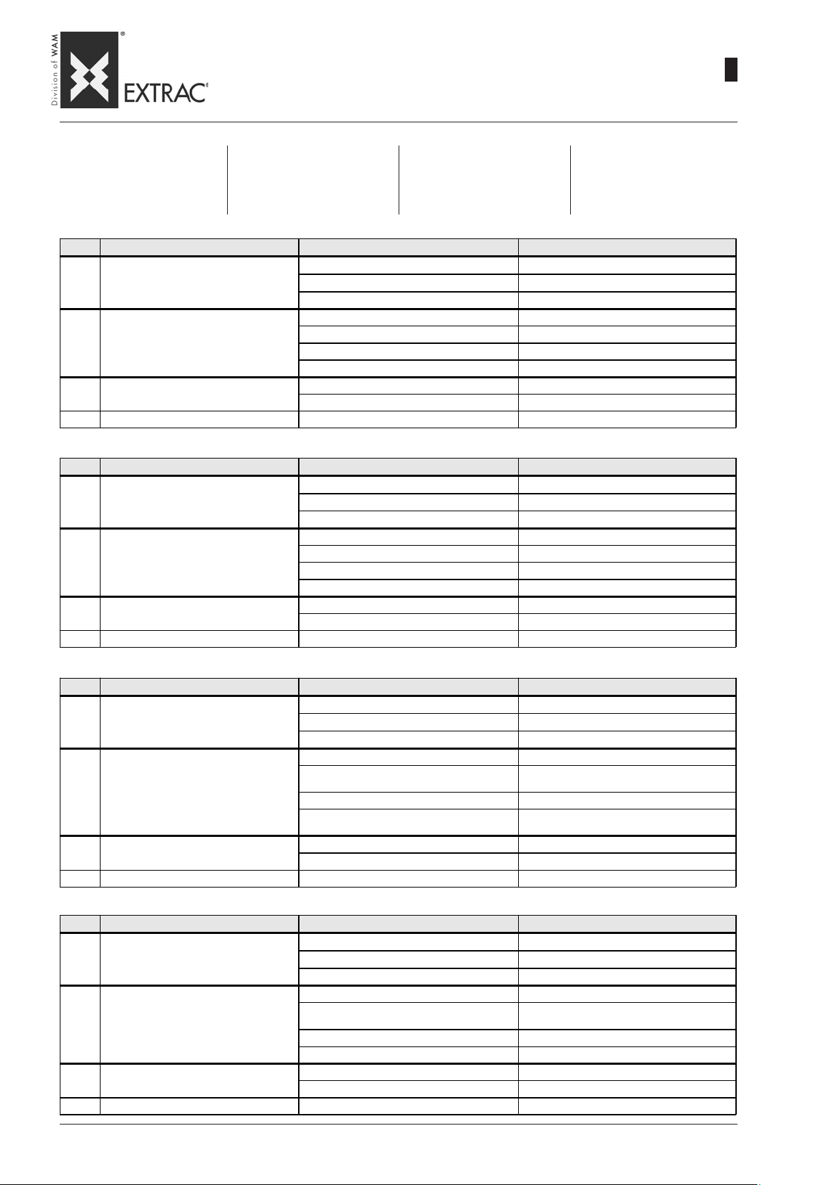
SBB
-
TROUBLE-SHOOTING
-
FEHLERSUCHE
-
RECHERCHE DES PANNES
-
RICERCA GUASTI
09.07
WA.14 M.
2
45
Minor problems may often be solved
without calling a technician.
The most common faults with relevant solutions are given in the Table
below.
N. Problem Cause Solution
1 V i b r ato r d o e s not work .
2 Product does not flow down.
3 Product under the hopper..
4 Hopper vibrates irregularly.s. Damper(s) damaged. Locate, then replace.
N. Problem Ursache Abhilfe
1 Vibrationsmotor funktioniert nicht.
2 Produkt wird nicht gefördert.
3 Unter Trichter tritt Produkt aus.
4 Unregelmäßige Vibrationen des Trichters. Bruch der Schwingungsdämpfer. Ursache suchen und ersetzen.
Kleinere Probleme können oft ohne
die Einschaltung eines Fachmanns
behoben werden. Hier folgt eine Aufstellung der häufigsten Probleme und
deren Abhilfe.
Connection not made. Check fuses.
Incorrect voltage. Correct voltage.
Vibrator. Replace faulty parts.
Insufficient vibration. Adjust vibrator size value.
Outlet is obstructed. Check extraction system below outlet.
Valve closed.. Open.
Vibrator burnt out. Check; replace the vibrator if necessary.
Hatchway seal damaged.t. Locate cause, then replace if necessary.
Welded joints are cracked. Repair welds immediately.
Kein Anschluß.. Sicherungen prüfen..
Fals c he Spannun g . Spa nnung a npass en.
Vibrationsmotor defekt. Defektes Teil ersetzen.
Schlechte Vibration. Unwuchtmassen im Motor ersetzen.
Verstopfung des Auslaufs. Austragesystem stromab vom Trichter prüfen.
Klappe oder Schieber geschlossen. Klappe oder Schieber öffnen.
Vibrationsmotor durchgebrannt. Ursache suchen und Vibrationsmotor ersetzen.
Dichtung der Klappe beschädigt. Ursache suchen und dann ersetzen.
Risse in der Schweißnaht. S ofort reparieren.
Les problèmes mineurs peuvent être
résolus sans consulter un spécialiste.
Vous trouverez ci-dessous une liste
des inconvénients les plus communs
avec les solutions éventuelles.
I problemi minori possono essere risolti senza consultare uno specialista.
Diamo di seguito un elenco degli inconvenienti più comuni con le eventuali soluzioni.
N. Problème Cause Remède
Absence de courant.. Contrôler les fusibles.
1 Le motovibrateur ne fonctionne pas
2 Le produit ne descend pas.
3 Présence de produit sous la trémie
4 Vibration décomposée de la trémie. Rupture d'un anti-vibrant.. Rechercher la cause et le remplacer.
N. Problema Causa Soluzione
1 Il motovibratore non funziona.
2 Il prodotto non scende.
3 Presenza prodotto sotto la tramoggia.
4 Vibrazione scomposta della tramoggia. Rottura di un antivibrante/i. S coprire il motivo e sostituirlo/i.
Te nsi on e r r oné e. Ada pter la te nsi on.
Motovibrateur défectueux.. Changer le composant défectueux.
Vibration faible. Régler les masses du motovibrateur.
Obstruction de la bouche de sortie.
Vanne ferm ée. Ouvrir l a va nne. .
Motovibrateur brûlé.
Joint de trappe endommagé. Rechercher la cause puis le remplacer.
Présence de criques dans les soudurese Réparer immédiatement.
Manca il collegamento. Controllare fusibili.
Te nsi one err ata. Adegua re l a te nsi one .
Motovibratore difettoso. Sostituire il componente difettoso.
Vibrazione scarsa. Regolare masse motovibratore.
Ostruzione della bocca di scarico.
Valvola o serranda chiusa. Aprire la valvola o serranda.
Motovibratore bruciato. Indagare il motivo poi sostituire il motovibratore.
Guarnizione boccaporto danneggiata. Scoprire il motivo e poi sostituirla.
Presenza di cricche nelle saldature Riparare immediatamente.
Contrôler le système d'extraction en aval du
fond.
Rechercher la cause puis remplacer le
motovibrateur.e.
Controllare sistema di estrazione a valle del
fondo
Page 94

Page 95

N.B. Rights reserved to modify technical specifications
N.B. Angaben ohne Gewähr. Änderungen können ohne Vorankündigung vorgenommen werden.
N.B. Toutes données portées dans le présent catalogue n’engagent pas le fabricant. Elles peuvent être modifiéès à tout moment.
N.B. Tutti i dati riportati nel presente catalogo non sono impegnativi e possono subire variazioni in qualsiasi momento.
WAM S.p.A. - EXTRAC Division
Via Cavour, 338
I - 41030 Ponte Motta
Cavezzo (MO) - ITALY
fax
e-mail
internet
videoconferenze
+ 39 / 0535 / 618111
+ 39 / 0535 / 618226
[email protected]
www.wamgroup.com
+ 39 / 0535 / 49032
Page 96
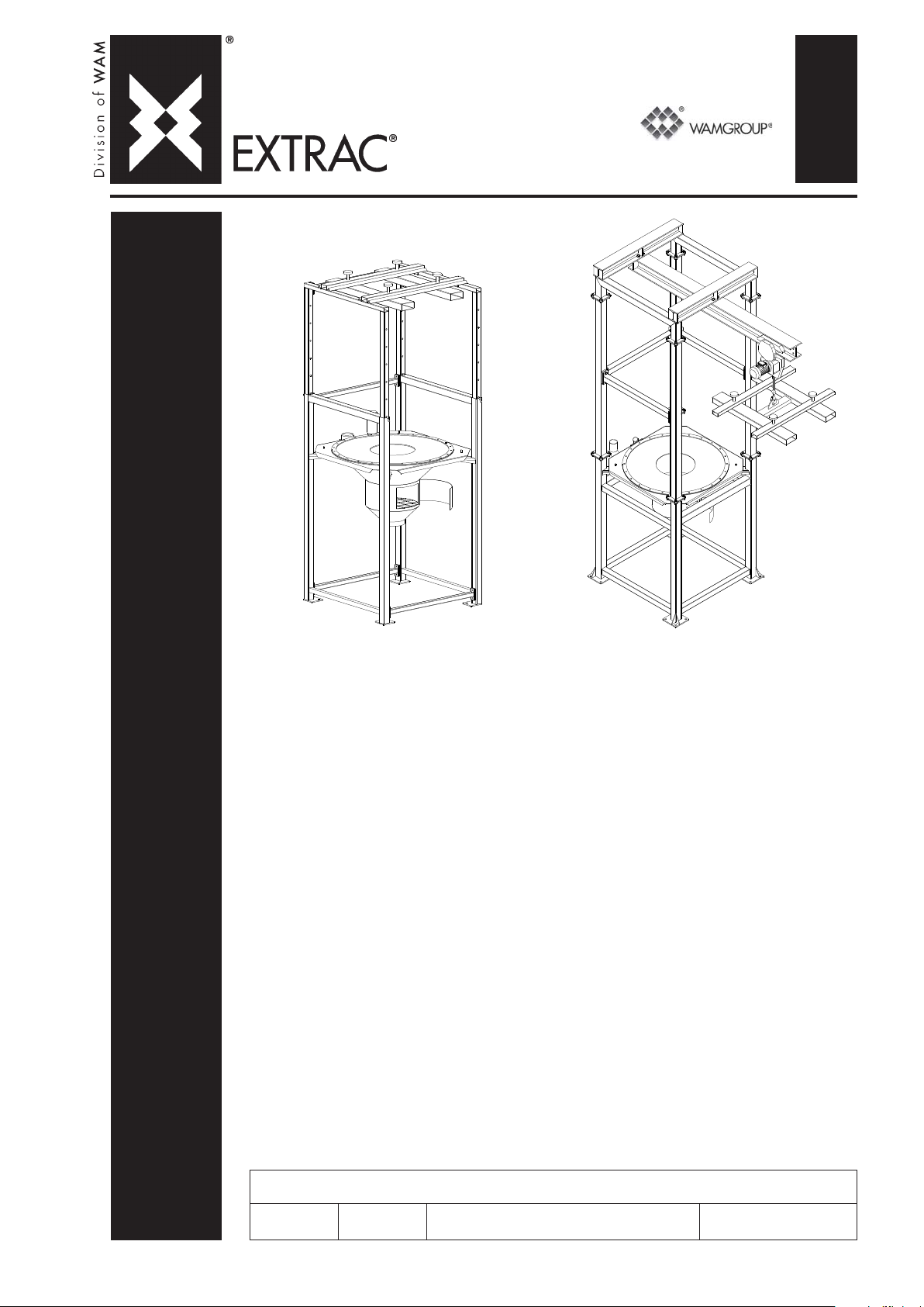
3
SPARE PARTS
SBB
• FLEXIBLE INTERMEDIATE BULK CONTAINER UNLOADER
SPARE PARTS CATALOGUE
• BIG-BAG - ENTLEERSTATION
ERSATZTEILKATALOG
• VIDE-SACS DE GRANDES DIMENSIONS
PIECES DE RECHANGE
• SVUOTA BIG BAG
PEZZI DI RICAMBIO
CATALOGUE No. WA.14 R.
All rights reserved © WAMGROUP
ISSUE
A5
CIRCULATION
100
LATEST UPDATE
11.07
Page 97

All the products described in this catalogue are manufactured according to WAM® S.p.A. Quality System
procedures.
The Company’s Quality System, certified in July 1994 according to International Standards UNI EN ISO 9002-94 and
extended to UNI EN ISO 9001-2000 in October, 2002, ensures that the entire production process, starting from the
processing of the order to the technical service after delivery, is carried out in a controlled manner that guarantees
the quality standard of the product.
Alle in diesem Katalog beschriebenen Erzeugnisse werden in Konformität mit dem Qualitätssystem der WAM
S.p.A. hergestellt.
Das im Juli 1994 zertifizierte Qualitätssystem entspricht der Norm UNI EN ISO 9002-94 (im Oktober 2002 auf
UNI EN ISO 9001-2000 erweitert) und gewährleistet dem Kunden eine strenge Qualitätskontrolle in jeder Phase
des Produktionprozesses bis hin zum Kundendienst nach Auslieferung der Ware.
Tous les produits décrits dans ce catalogue ont été réalisé selon les modalités opérationnelles définies Système
de Qualité de WAM® S.p.A.
Le système de Qualité de l’entreprise, certifié au mois de juillet 1994 en conformité aux Normes Internationales UNI
EN ISO 9002-94 et successivement étendu à UNI EN ISO 9001-2000 au mois de octobre 2002, est en mesure
d’assurer que le procédé entier de production, à partir de la formulation de la commande jusqu’au service technique
après la livraison, soit effectué de manière contrôlée et appropriée afin de garantir le standard de qualité du produit.
Tutti i prodotti descritti in questo catalogo sono stati realizzati secondo modalità operative definite Sistema
Qualità di WAM® S.p.A.
Il Sistema Qualità aziendale, certificato dal luglio 1994 in conformità alle Normative Internazionali UNI EN ISO
9002-94 e successivamente esteso alle Normative Internazionali UNI EN ISO 9001-2000 nell’ottobre 2002, è in
grado di assicurare che l’intero processo produttivo, dalla formulazione dell’ordine fino all’assistenza tecnica
successiva alla consegna, venga effettuato in modo controllato ed adeguato a garantire lo standard qualitativo
del prodotto.
®
UNI EN ISO 9001-2000
Certified Company
This publication cancels and replaces any previous edition and revision.
We reserve the right to implement midifications without notice.
This catalogue cannot be reproduced, even partially, without prior consent.
Diese Veröffentlichung annuliert und ersetzt jeder hergehende Edition oder Revision.
WAM® behält sich das Recht vor, Anderungen ohne vorherige Informationen durchzuführen.
Cette publication annule et remplace toutes les autres précédentes.
La reproduction et la publication partielle ou totale de ce catalogue est interdite sans notre autorisation.
Nous nous réservons le droit d’apporter toutes modifications à nos produits.
Questa pubblicazione annulla e sostituisce ogni precedente edizione o revisione.
Ci riserviamo il diritto di apportare modifiche senza preavviso.
E’ vietata la riproduzione anche parziale senza autorizzazione.
Page 98
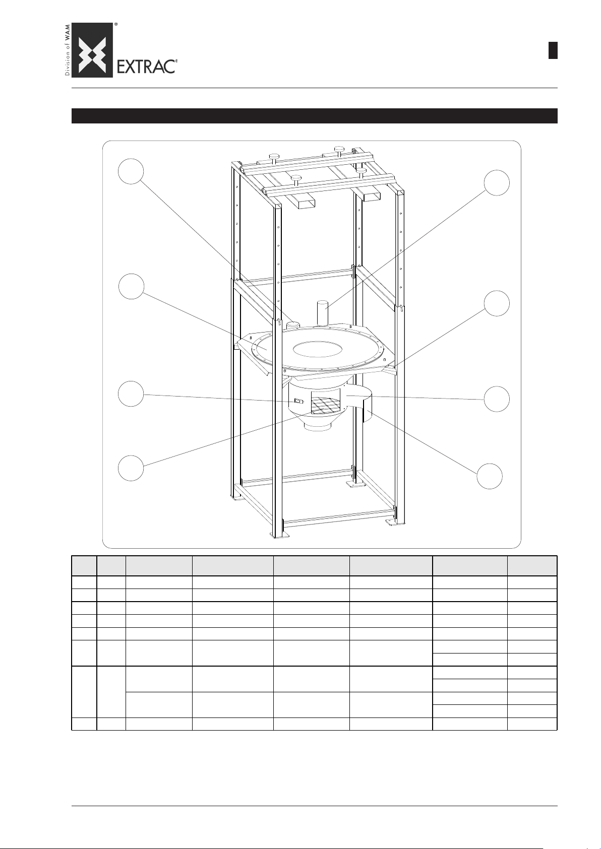
06
07*
-
SPARE PARTS
-
SBB
ALL MODELS - ALLE MODELLE - TOUS LES MODÈLES - TUTTI I MODELLI
ERSATZTEILE
-
PIÈCES DE RECHANGE
-
RICAMBI
05*
11.07
WA.14 R.
3
01
•
•
•
•
08
•
•
•
•
01
ITEM
QT.Y
POS.
MENGE
01 1 SAFETY GRILLE SICHERHEITSGITTER GRILLE DE SÉCURITÉ GRIGLIA DI SICUREZZA All - Alle - Tous - Tut te
02 1 HATCH S EA L KLAP PE NDICHTUN G J OINT DE TRAP PE GUARNIZIONE P ORTEL LO A ll - Alle - Tous - Tu tte
03* 4 DAMPER SCHWINGUNGSDÄMPFER SILENT-BLOC ANTIVIBRANTE All - Alle - Tous - Tu tte
04 ACCESS DOOR INSPEKTIONKLAPPE PORTE PORTELLO All - Alle - Tous - Tut te
05* 1 FILTER BAG FILTERSACK MANCHON FILTRANT MANICA FILTRANTE All - Alle - Tous - Tut te
06 1 STD MOTOV IBRATOR V IBRATIONSMO TOR STD MOTOVIB RATEUR S TD MOTOV IBRATORE STD
07* 1
08 1 LOOK HOOK VERSCHLUßHAKEN CROCHET DE FERM. GANCIO CHIUSURA All - Alle - Tous - Tu tte
* = RECOMMENDED SPARE PARTS
* = EMPFOHLENE ERSATZTEILE
* = PIÈCES DÉTACHÉES CONSEILLÉES
* = RICAMBI CONSIGLIATI
DESCRIPTION BENENNUNG DÉSIGNATION DENOMINAZIONE
STD SEAL Black DICHTUNG STD Schwarze JOINT STD Noir GUARNIZIONE Nera STD
SEA L white DICHTUNG Weiße JOINT Blanc GUARNIZIONE Bia nca
Typ e
SBB
SBB125
SBB150
SBB125
SBB150
SBB125
SBB150
03*
02
04
Code
206F4BQ2A
20994512A
2099574TA
206F4BNZA
2099580ZA
VBOL101311
VBOL201311
19ZAQN5TA
19ZAQN7TA
19ZAQN6TA
19ZAQN8TA
20995731A
Page 99
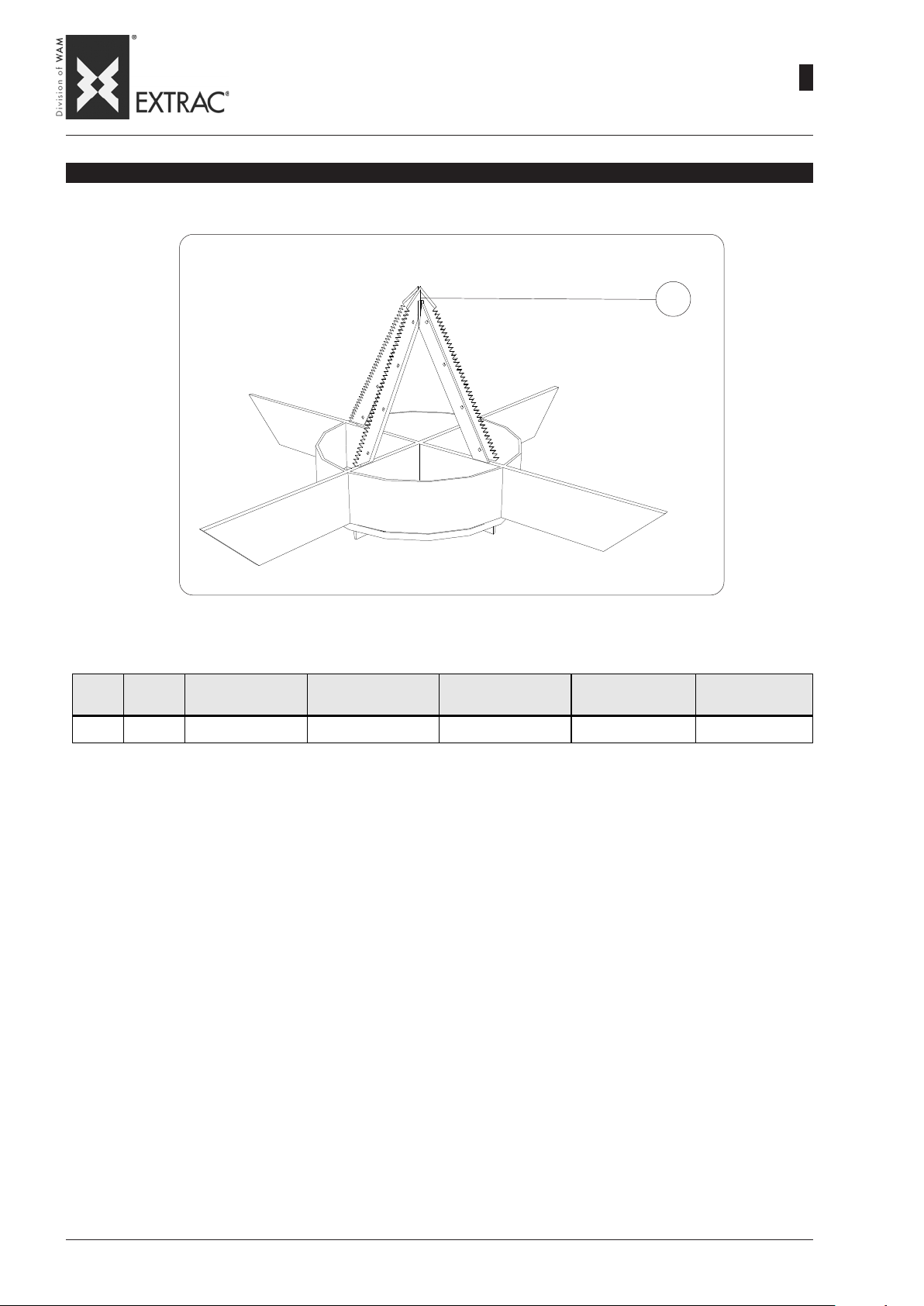
-
SPARE PARTS
-
SBB
CUTTING SYSTEM - SCHNEIDEVORRICHTUNG - SYSTÈME DE COUPE - SISTEMA DI TAGLIO
ERSATZTEILE
-
PIÈCES DE RECHANGE
-
RICAMBI
01
WA.14 R.
11.07
3
02
ITEM
POS.
01 4 CUTTING BLADES SCHNITTMESSER LAMES DE COUPE LAME DI TAGLIO 206FWGU2A
QTY
MENGE
DESCRIPTION BENENNUNG DÉSIGNATION DENOMINAZIONE Cod.
Page 100

SBB
-
SPARE PARTS
-
ERSATZTEILE
-
PIÈCES DE RECHANGE
-
RICAMBI
11.07
WA.14 R.
3
03
PROCEDURE FOR PARTS REPLACEMENT
ITEM 6
REPLACING SEAL
- Disconnect power supply to
the panel and terminal board.
- Unscrew the screws blocking
the seal to the underlying hopper.
- Remove the seal and replace
it.
- Restore the power supply connections.
ITEM 3
REPLACING DAMPERS
- Disconnect power supply to
the motor and panel.
- Harness the hopper and support it using suitable lifting
equipment that will keep it balanced.
- Unscrew the four fixing
screws which fix the dampers to the supporting frame.
- Remove the dampers and replace them.
- Repeat the operations in reverse order.
- Restore the electrical connections.
AUSTAUSCH VON ERSATZTEILEN
POS. 6
AUSTAUSCH DER DICHTUNG
- Den elektrischen Anschluß am
Schaltkasten und der Klemmenleiste abtrennen.
- Die Schrauben lösen, welche
die Dichtung am unteren Trichter befestigen.
- Die Dichtung entfernen und ersetzen.
- Die elektrischen Anschlüsse
wieder herstellen.
POS. 3
ERSETZEN DER SCHWINGUNGSDÄMPFER
- Den elektrischen Anschluß am
Motor und am Schaltkasten unterbrechen.
- Den Trichter anschlagen und
mit einem geeigneten Hebezeug im Gleichgewicht halten.
- Die vier Schrauben lösen, mit
denen die Schwingungsdämpfer an den Gestellträgern befestigt sind.
- Die Schwingungsdämpfer
entfernen und ersetzen.
- Zusammenbau in umgekehrter
Reihenfolge vornehmen.
- Die elektrischen Anschlüsse
wieder herstellen.
PROCÉDURES POUR LE REMPLACEMENT DES PIÈCES DETACHEES
POS. 6
REMPLACEMENT DU JOINT
- Débrancher le raccordement
électrique au tableau et au bornier.
- Dévisser les vis de serrage qui
bloquent le joint à la trémie inférieure.
- Enlever et changer le joint.
- Rétablir les raccordements
électriques.
POS. 3
REMPLACEMENT DES SILENTBLOCS
- Débrancher le raccordement
électrique au moteur et au tableau.
- Elinguer la trémie et la soutenir
avec un moyen de levage approprié pour la maintenir en
équilibre.
- Dévisser les quatre vis de serrage qui bloquent les silentblocs
aux supports du châssis.
- Enlever et changer les silentblocs.
- Exécuter les opérations dans
l’ordre inverse.
- Rétablir les raccordements
électriques.
PROCEDURA PER LA SOSTITUZIONE DELLE PARTI DI RICAMBIO
POS. 6
SOSTITUZIONE GUARNIZIONE
- Disconnettere l’ allacciamento
elettrico al quadro e alla morsettiera.
- Svitare le viti di serraggio che
bloccano la guarnizione alla
tramoggia inferiore.
- Rimuovere e sostituire la guarnizione.
- Ripristinare i collegamenti elettrici.
POS. 3
SOSTITUZIONE ANTIVIBRANTI
- Disconnettere l’ allacciamento
elettrico al motore e al quadro.
- Imbragare la tramoggia e sostenerla con mezzo di sollevamento idoneo in modo da tenerla in equilibrio.
- Svitare le quattro viti di serraggio che bloccano gli antivibranti
ai sostegni del telaio.
- Rimuovere e sostituire gli antivibranti.
- Eseguire le operazioni in senso inverso.
- Ripristinare i collegamenti elettrici.
ITEM 4
REPLACING FILTER BAG
- Slacken the locking clamp
- Remove the filter bag and replace it.
- Refit the clamp.
ITEM 5
REPLACING VIBRATOR
- Disconnect power supply to
the terminal board and panel
- Remove the fixing bolts.
- Remove the vibrator safety cable.
- Install the new vibrator.
- Refit the safety cable.
- Restore the electrical connections.
POS. 4
AUSTAUSCH DES FILTERSCHLAUCHS
- Die Befestigungsschelle lösen.
- Den Filterschlauch entfernen
und ersetzen.
- Die Befestigungsschelle
wieder anschrauben.
POS. 5
AUSTAUSCH DES SCHWINGUNGSDÄMPFERS
- Den elektrischen Anschluß an
der Klemmenleiste und dem
Schaltkasten unterbrechen.
- Die Befestigungsschrauben
entfernen.
- Das Sicherheitskabel des
Schwingungsdämpfers entfernen.
- Den neuen Schwingungsdämpfer einbauen.
- Das Sicherheitskabel wieder
befestigen.
- Elektrische Anschlüsse vornehmen.
POS. 4
REMPLACEMENT DU MANCHON FILTRANT
- Dévisser le collier de blocage.
- Enlever et remplacer le manchon filtrant.
- Revisser le collier.
POS. 5
REMPLACEMENT DU VIBRATEUR
- Débrancher le raccordement
électrique du bornier et du tableau.
- Enlever les boulons de fixation.
- Enlever le câble de sécurité du
vibrateur.
- Installer le nouveau vibrateur.
- Remettre le câble de sécurité.
- Rétablir les raccordements
électriques.
POS. 4
SOSTITUZIONE MANICA FILTRANTE
- Svitare la fascetta di bloccaggio.
- Rimuovere e sostituire la manica filtrante.
- Riavvitare la fascetta.
POS. 5
SOSTITUZIONE VIBRATORE
- Disconnettere l’ allacciamento
elettrico alla morsettiera e al
quadro
- Togliere i bulloni di fissaggio.
- Togliere il cavo di sicurezza del
vibratore.
- Installare il nuovo vibratore.
- Reinserire il cavo di sicurezza.
- Ripristinare i collegamenti elettrici.
 Loading...