

Walz MINI-PAM-II User Manual

MINI-PAM-II
Manual for
Standalone Use
2.163/04.2018
3. Edition, May 2018
MINI_PAM_II_03.docx
Heinz Walz GmbH, 2018
Heinz Walz GmbH • Eichenring 6 • 91090 Effeltrich • Germany
Phone +49-(0)9133/7765-0 • Telefax +49-(0)9133/5395
E-mail info@walz.com • Internet www.walz.com


Contents Chapter 1
1 Contents
1 Contents .............................................................. 1
2 Safety Instructions .............................................. 1
General Safety Instructions ............................................ 1
2.1
2.2 Special Safety Instructions .............................................. 1
3 Introduction ......................................................... 3
Overview ............................................................................... 4
3.1
4 Components and Setup ...................................... 7
Extent of Delivery (Basic System) ................................ 7
4.1
4.2 Optoelectronic Unit ............................................................ 8
4.2.1 Batteries .............................................................................. 11
4.3 2010-A Distance Clip 60° .............................................. 11
4.4 Accessories........................................................................ 13
4.4.1 2035-B Leaf-Clip Holder ................................................ 13
4.4.2 DLC-8 Dark Leaf Clip ...................................................... 16
4.4.3 2060-B Arabidopsis Leaf Clip....................................... 18
4.4.4 2060-A Fiberoptics Holder for Surfaces .................... 18
4.4.5 2065-M Mini Quantum/Temp.-Sensor ....................... 19
4.4.6 2054-L External LED Source ....................................... 20
4.4.7 MINI-SPEC/MP Miniature Spectrometer .................. 22
4.4.8 KS-2500 Suspension Cuvette ...................................... 27
4.4.9 Oxygen Package .............................................................. 27
4.4.10 BCS-9590 Barcode Scanner ........................................ 28
4.4.11 MINI-PAM/F1 Miniature Fiberoptics ........................... 29
4.4.12 MQS-B/A Adapter Set for Thin Fiberoptics .............. 30
5 Saturation Pulse Analysis ................................ 31
Five Fluorescence Levels.............................................. 31
5.1
5.1.1 Measurements with Dark-Acclimated Samples ...... 32
5.1.2 Measurements with Illuminated Samples ................. 32
C1

Chapter 1 Contents
C2
5.2 Fluorescence Ratio Parameters .................................. 36
5.3 Relative Electron Transfer Rate (ETR) ...................... 38
5.4 Light Curves ....................................................................... 39
5.5 Some Light Curve References ..................................... 42
5.6 Some Reviews on Saturation Pulse Analysis .......... 43
6 Hints & Troubleshooting ...................................45
Instrument Settings .......................................................... 45
6.1
6.2 Default settings ................................................................. 45
6.3 F0 Fluorescence ............................................................... 46
6.5 Signal Noise ....................................................................... 48
6.6 System Hangs ................................................................... 48
6.7 External PAR Sensor is not Responding .................. 48
6.8 Intensity of external lamp cannot be adjusted ......... 48
7 Touchscreen Operation .....................................49
Calibration ........................................................................... 49
7.1
7.2 Top Level Windows ......................................................... 50
7.2.1 Basic Data .......................................................................... 52
7.2.2 Primary Data ...................................................................... 55
7.2.3 Quenching Analysis ......................................................... 56
7.2.4 Ft-Chart ................................................................................ 57
7.2.5 Spectrometer ..................................................................... 58
7.2.6 Actinic + Yield .................................................................... 60
7.2.7 Induction Curve ................................................................. 61
7.2.8 Light Curve ......................................................................... 64
7.2.9 Recovery ............................................................................. 64
7.2.10 Actinic Light List ................................................................ 66
7.3 Main Menu .......................................................................... 70
7.3.1 PAM Settings ..................................................................... 70
7.3.1.1 Meas. Light ......................................................................... 71
7.3.1.2 Meas. Light Sett. ............................................................... 72
7.3.1.3 Gain ...................................................................................... 74

Contents Chapter 1
7.3.1.4 Damping .............................................................................. 74
7.3.1.5 ETR-Factor ........................................................................ 75
7.3.1.6 Fo’ Mode ............................................................................. 75
7.3.1.7 Adjust F-Offset .................................................................. 75
7.3.2 Light Sources .................................................................... 77
7.3.2.1 Far Red Sett. ..................................................................... 78
7.3.2.2 Light Panel Sett. ............................................................... 78
7.3.2.3 SAT Settings ...................................................................... 79
7.3.3 Program/Clock Settings ................................................. 80
7.3.3.1 Actinic + Yield.................................................................... 81
7.3.3.2 Induction Curve ................................................................ 82
7.3.3.3 Light Curve ......................................................................... 83
7.3.4 Sensors ............................................................................... 85
7.3.4.1 Internal PAR ...................................................................... 86
7.3.4.2 Leaf Clip/Ext. PAR ........................................................... 88
7.3.4.3 Oxygen Sensor ................................................................. 92
7.3.4.4 Spectrometer ..................................................................... 93
7.3.4.5 Load System Settings ..................................................... 96
7.3.5 MINI-PAM-II Settings ...................................................... 96
7.3.6 Memory ............................................................................. 101
7.3.7 Info ...................................................................................... 101
7.3.7.1 MINI-PAM-II Info............................................................. 102
7.3.7.2 Sensor Info...................................................................... 103
7.3.7.3 Firmware Info ................................................................. 104
8 Specifications MINI-PAM-II ............................. 105
Basic System ................................................................... 105
8.1
8.1.1 Optoelectronic Unit ........................................................ 105
8.1.2 Fiberoptics MINI-PAM/F .............................................. 107
8.1.3 Power Supply MINI-PAM-II/N..................................... 107
8.1.4 Battery Charger 000190101101 ................................ 108
8.1.5 Distance Clip 60° 2010-A ............................................ 108
C3

Chapter 1 Contents
C4
8.1.6 Complementary Items ................................................... 108
8.1.7 Software WinControl-3 .................................................. 108
8.1.8 Transport Case MINI-PAM/T ...................................... 109
8.2 Accessories ...................................................................... 109
8.2.1 2035-B Leaf-Clip Holder ............................................... 109
8.2.2 Fiberoptics Adapter 90° 2030-B90 ............................ 110
8.2.3 2054-L External LED Source ...................................... 110
8.2.4 Dark Leaf Clip DLC-8 .................................................... 111
8.2.5 Arabidopsis Leaf Clip 2060-B ..................................... 111
8.2.6 Fiberoptics Holder for Surfaces 2060-A .................. 112
8.2.7 Mini Quantum/Temp.-Sensor 2065-M ..................... 112
8.2.8 Miniature Spectrometer MINI-SPEC/MP ................. 113
8.2.8.1 Flat Entrance Optics SPEC/P ..................................... 113
8.2.8.2 Fluorescence and Reflection Optics SPEC/R ....... 113
8.2.8.3 PAR Calibration Block 000160101439 .................... 114
8.2.9 Suspension Cuvette KS-2500 .................................... 114
8.2.10 Magnetic Stirrer with Fiberoptics Holder MKS-2500
.............................................................................................. 115
8.2.11 Compact Tripod ST-2101A .......................................... 115
8.2.12 MINI-PAM/F1 Miniature Fiberoptics ......................... 115
9 Warranty ........................................................... 117
9.1 Conditions ......................................................................... 117
9.2 Instructions ....................................................................... 118
10 Index ................................................................. 119

Safety Instructions Chapter 2
2 Safety Instructions
2.1 General Safety Instructions
- Read safety instructions and the operating instructions
prior to operation of the device and its accessories.
- Pay attention to all safety warnings.
- Keep device and its accessories away from water or
high moisture areas.
- Keep the device and its accessories away from dust,
sand and dirt.
- Do not put the device and its accessories near sources
of heat.
- Ensure that neither liquids nor foreign bodies get inside
the device or its accessories.
- Ensure sufficient ventilation.
- Connect the device only to the power source indicated
in the operating instructions or on the device. If the device is not in use, remove the mains plug from the socket.
- The device and its accessories should only be repaired
by qualified personnel.
2.2 Special Safety Instructions
- The MINI-PAM-II is a highly sensitive instrument which
should be only used for research purposes, as specified
1

Chapter 2 Safety Instructions
2
in this manual. Follow the instructions of this manual in
order to avoid potential harm to the user and damage to
the instrument.
- The MINI-PAM-II can emit very strong light! In order to
avoid harm to your eyes, never look directly into the light
port of the MINI-PAM-II or its fiberoptics.
- Switch off MINI-PAM-II before connecting or disconnection 2054-L External LED Source.

Introduction Chapter 3
3 Introduction
- The “Photosynthesis Yield Analyzer MINI-PAM-II” has been
designed for highly sensitive saturation pulse analysis of
photosystem II (PS II) in the field as well as in the laboratory.
The automatically calculated parameters are F
(maximum photochemical yield), Y(II) (effective photochemical yield) and its complementary yields Y(NPQ) and Y(NO),
as well as parameters of photochemical (qL, qP) and nonphotochemical quenching (q
, NPQ) (see Table 3, page 34).
N
- The instrument continues the tradition of the preceding MINIPAM chlorophyll fluorometer. The major technical advancements of the MINI-PAM-II are the consistent use of energyefficient LEDs, an internal PAR sensor, and stand-alone operation by a touchscreen which is well readable under natural light conditions. Also, a far red LED has been added for
selective photosystem I excitation.
V/FM
- A further technical progress is the newly designed leaf clip
sensor (2035-B) which measures photosynthetically active
radiation (PAR) at leaf level with high accuracy and, thus,
provides reliable light intensity data for calculations of electron transport rates (ETR).
- A variety of add-ons make the MINI-PAM-II a highly versatile
measuring system which can be configured to meet the
needs of the research goal. The range of accessories includes a multi-colored lighting unit (Section 4.4.6, page 20),
an optical oxygen sensor (Section 4.4.9, page 27) and a
miniature spectrometer (Section 4.4.7, page 22).
- For long-term field campaigns, the memory capacity has
been upgraded to keep data of more than 27,000 saturation
3

Chapter 3 Introduction
4
pulse analyses. The fluorometer is powered by of-the-shelf
AA (Mignon) batteries which are easily replaceable even under field conditions. One set of batteries lasts for up to 1000
saturation pulse analyses.
- The MINI-PAM-II can be operated in the stand-alone mode
or by the well-proven WinControl-3 software. WinControl-3
has been introduced with the JUNIOR-PAM fluorometer and
now operates many other fluorometers like the DIVINGPAM, MONITORING-PAM, and WATER-PAM. In addition to
the features available in the stand-alone mode, the software
allows evaluations of light-response curves by a non-linear
fitting routine and automatic execution of custom-designed
experiments using the built-in batch file feature.
3.1 Overview
The MINI-PAM-II fluorometer provides a vast range of settings
and protocols for measuring fluorescence. To make full use of
these opportunities, it is necessary to become acquainted with
terminology and principles of saturation pulse analysis. Therefore, the present manual provides a chapter dealing with the basics of saturation pulse analysis (Chapter 5, page 31).
Chapter 5 also provides a short list of review papers on PAM
chlorophyll fluorescence and saturation pulse analysis (page 43).
Further, a small section is included providing some hints for beginners (Chapter 6, page 45).
In the field, the MINI-PAM-II is mostly operated in the standalone mode by its touchscreen. Chapter 7 (page 49) provides detailed instructions on how to use the touchscreen interface including advices on fluorescence induction and light curve programs.

Introduction Chapter 3
Also, this manual includes a section on safe handling of the
MINI-PAM-II (Chapter 2, page 1), and on the extent of delivery of
the basic fluorescence system and its accessories (Chapter 1,
page 7). Further, technical information (Chapter 8, page 105)
and warranty conditions (Chapter 9, page 117) are provided.
5


Components and Setup Chapter 4
4 Components and Setup
4.1 Extent of Delivery (Basic System)
Optoelectronic Unit MINI-PAM-II/B or -/R
Fiber optics MINI-PAM/F
Power Supply MINI-PAM-II/N
Battery charger 000190101101
Battery (12 x) 000160101990
USB cable type A to Mini B 000130606252
Distance Clip 60° 2010-A
Sloped Plexiglas rack 000240313614
Stylus 000160201311
Carrying strap 000150401922
Software WinControl-3
MINI-PAM-II Manual
WinControl-3 Software
7
Chapter 4 Components and Setup
8
Fig.
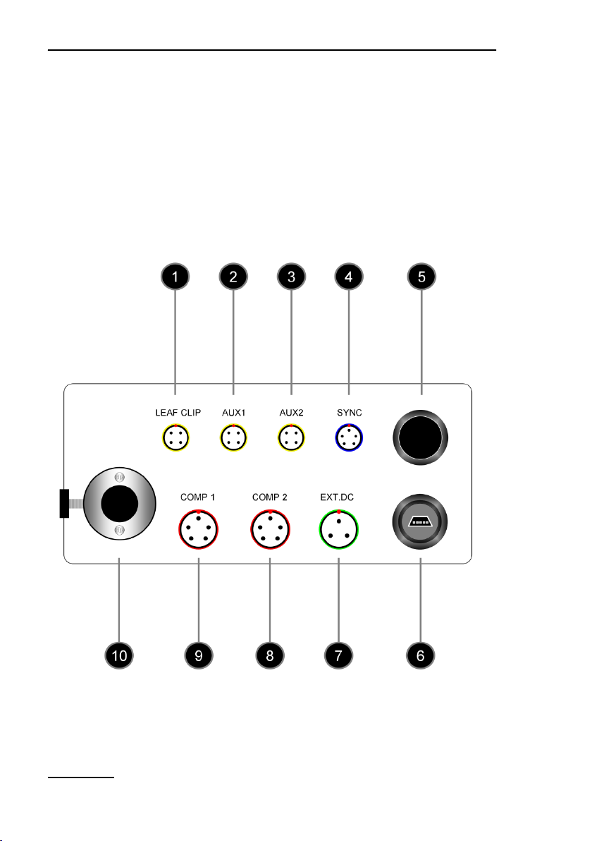
4.2 Optoelectronic Unit
Sockets, fiber optics port and on/off switch of the back side of the
MINI-PAM-II are outlined and numbered in Fig. 1, their properties
and functions are explained in Table 1, page 9.
1: Back panel of MINI-PAM-II Power-and-Control-Unit
Components and Setup Chapter 4
Table 1: Backside of MINI-PAM-II.
2
1 3 4 5 6 7 8 9 10
Numbering refers
to Fig. 1, page 8
Function
LEAF CLIP
Socket for 2035-B Leaf-Clip Holder
AUX 1
Electronically configured as LEAF CLIP socket
AUX 2
Electronically configured as LEAF CLIP socket
SYNC
Socket for external light source which emits synchronized with
MINI-PAM-II measuring light
ON/OFF
MINI-PAM-II switch
USB SOCKET
Receptacle for MINI-B USB plug.
EXT. DC
Socket for Power Supply MINI-PAM-II/N
COMP 2
Prepared for peripherals mastering RS232 communication (e.g.
bar code scanner)
COMP 1
Electronically configured as COMP 2
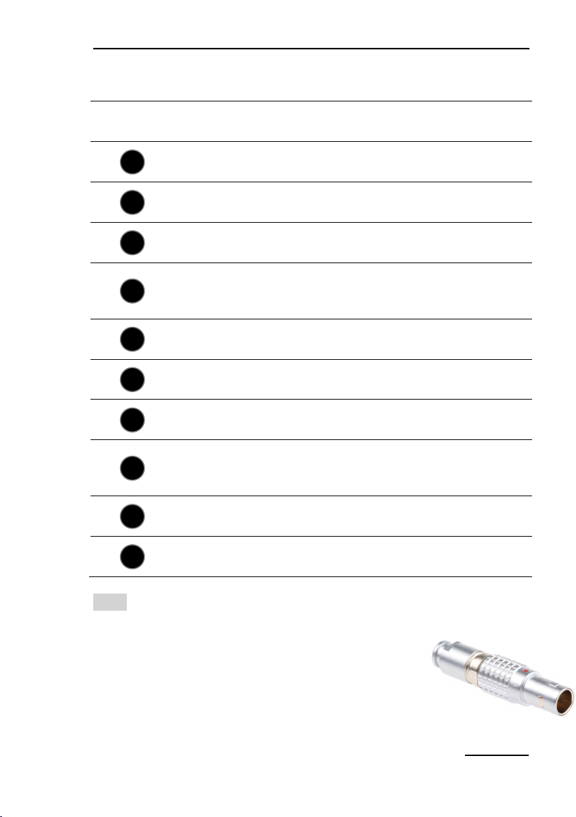
Note Great caution should be exercised to prevent dirt or foreign
matter from entering the ports or sockets of the MINI-PAM -II. Do
not force a plug into the wrong socket. Orientate
each plug so that the red dot on the plug coincides with the red dot of the socket. Do not try to
disconnect a plug by pulling at the cable. Disconnect plug by pulling at the rippled bushing of the plug.
LIGHT PORT
Port for Fiberoptics MINI-PAM/F
9
Chapter 4 Components and Setup
10
Fig.
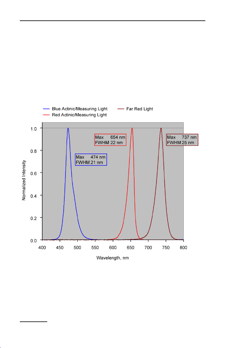
Two versions of the MINI-PAM -II fluorometer are available. The
MINI-PAM-II/B fluorometer is equipped with a blue LED which is
replaced by a red LED in the MINI-PAM-II/R fluorometer. This
LED is electronically driven to act as measuring and as actinic
light source. In addition, both versions of the MINI-PA M-II offer a
far red LED. Normalized spectra of blue, red and far red LEDs
are shown in Fig. 2.
2: Normalized Emission Spectra of MINI-PAM II LEDs. Normalized
emission spectra of blue LED (MINI-PAM-II/B), red LED (MINI-PAMII/R) and far red LED (MINI-PAM-II/B and R).

Components and Setup Chapter 4
Fig.
4.2.1 Batteries
When operated independently, the system is powered by six AA
(Mignon) rechargeable batteries (1.2 V/2 Ah). The system can
also be powered by non-rechargeable batteries. The battery
compartment of the opto-electronic unit does not have a charging
function. Therefore, the device can be connected to line power
even in the presence of non-rechargeable batteries.
The battery compartment is closed by an aluminum plate. Its
locking mechanism functions properly if the label “INNER FACE”
on the aluminum plate faces the batteries.
4.3 2010-A Distance Clip 60°
The 2010-A clip positions the fiberoptics end-piece relative to the
sample. The axis of the end-piece is positioned at a 60° angle
relative to the sample plane. Two different spacer rings may be
used to increase the distance between fiberoptics and sample.
In case of relative thick leaves, or when lichens and mosses are
examined, the sample may be placed below the hole of the
2010-A clip. Normal leaves are usually examined above this
3: Distance Clip 60° 2010-A
11
Chapter 4 Components and Setup
12
Fig.
hole. In the latter case, the leaf can be held between the folded
parts of the clip.
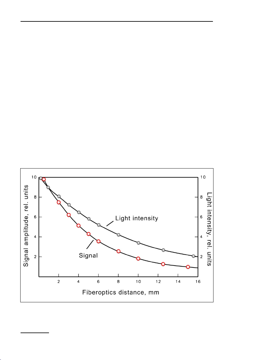
The distance between fiberoptics exit plane and sample has
considerable influence on signal amplitude and effective light intensities (Fig. 4, page 12). With a 60° angle between sample
plane and fiberoptics, the distance between leaf surface and fiber
optics varies. Hence, the leaf surface is exposed to slightly heterogeneous light intensities when actinic light is applied via the
fiberoptics. A much more pronounced intensity gradient exists inside the leaf due to shading by the top chloroplast layers. In essence, the measured signal will be dominated by that part of the
leaf which receives maximal intensity, as this also is most strongly excited by the measuring light and emits most of the fluorescence which is received by the fiberoptics.
4: Relationship between signal amplitude/light intensity and distance
between fiberoptics exit plane and sample
Components and Setup Chapter 4
Fig.
4.4 Accessories
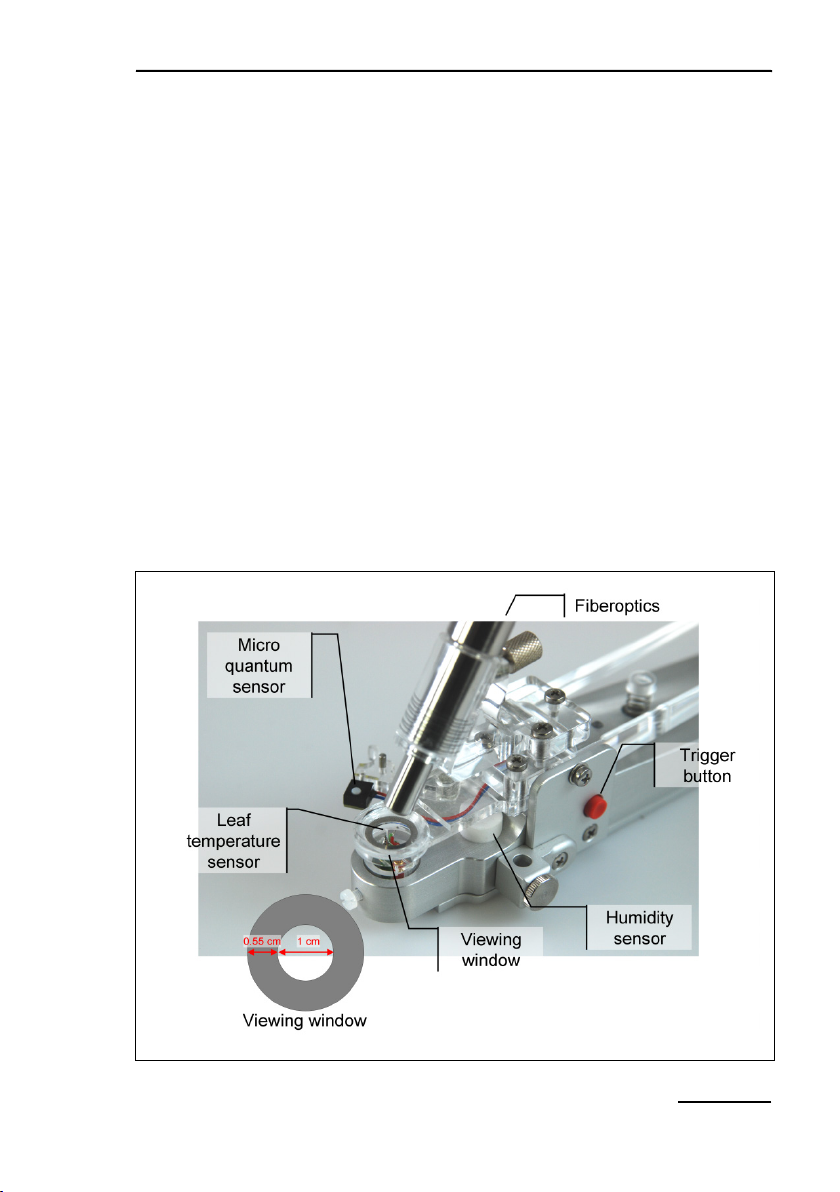
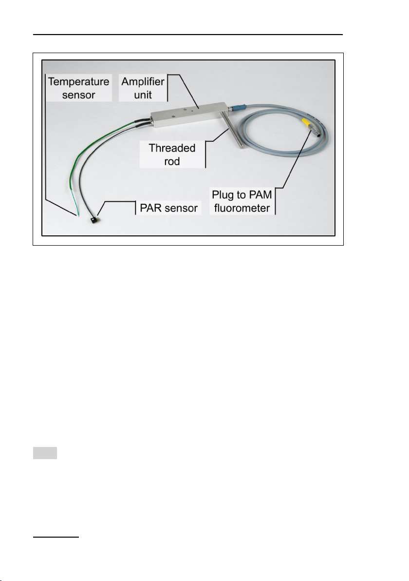
4.4.1 2035-B Leaf-Clip Holder
The Leaf-Clip Holder 2035-B must be connected to the LEAF
CLIP socket (Fig. 1, page 8) to record PAR, leaf temperature and
ambient humidity in parallel with chlorophyll fluorescence. In the
stand-alone mode, readings of environmental data are taken with
every saturation pulse analysis but these data can be continuously recorded when the MINI-PAM-II is operated by the WinControl-3 software.
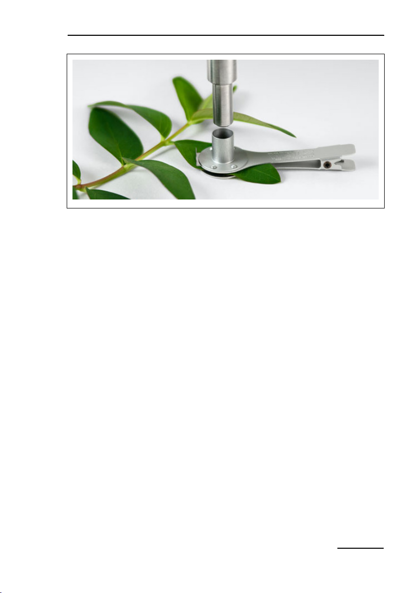
The Leaf-Clip Holder 2035-B is almost indispensable for field investigations, when ambient conditions may vary considerably. It
substitutes for the standard "Distance Clip" (2010-A) as a device
5: 2035-B Leaf-Clip Holder
13

Chapter 4 Components and Setup
14
for defined positioning of the fiberoptics relative to the leaf plane.
Also, using the PAR sensor of the leaf clip, the internal PAR sensor of the MINI-PAM-II can be readily calibrated.
In the 2035-B holder, the leaf is resting on a Perspex tube with
widened crest. The tube can be vertically adjusted to account for
different leaf thicknesses. The fiberoptics axis forms a 60° angle
with the leaf plane. Optionally, a 90° fiberoptics adapter (2030B90)
is available for applications requiring homogenous illumina-
tion by actinic light applied via the fiberoptics. The distance between fiberoptics and leaf can be varied. For most applications
the minimal distance is recommended (maximal signal). Larger
distances can be defined by spacer rings. The illuminated leaf
area is limited by a steel ring with 10 mm ∅ opening.
At the bottom of the Leaf-Clip Holder 2035-B, a tripod mounting
thread is provided. Mounting the device on a tripod (e. g. Compact Tripod ST-2101A) facilitates long term measurements with
the same plant.
The handle of the Leaf-Clip Holder 2035-B features a red pushbutton for remote control of the MINI-PAM-II. Pressing the button
triggers a saturation pulse and associated measurements of fluorescence levels for “fluorescence quenching analysis”.
Micro-Quantum-Sensor
A micro quantum sensor is integrated into the Leaf-Clip Holder
2035-B to monitor the photosynthetic active radiation (PAR, between 400 and 700 nm) to which the sample is exposed. The micro-quantum-sensor measures light intensity in µmol quanta m
-1
s
. The µmol quanta m-2 s-1 is the unit of photon flux density.
-2
Hence, the micro-quantum-sensor actually measures photosynthetic photon flux density (PPFD).

Components and Setup Chapter 4
Essential optoelectronic elements of this micro-quantum-sensor
are:
- A 3 mm ∅ diffusing disk.
- High stability silicon photovoltaic detector with filter set for
PAR correction, magnetically attached to 2035-B Leaf Clip
Holder.
- Cosine response characteristics (Angular dependence: Error
< 3 % for angle between -30 ° and +30 ° from normal axis).
The sensor is factory calibrated and calibration factors are stored
in the internal memory of the 2035-B leaf clip. The stability of calibration depends on keeping the diffuser clean. It is advisable to
check calibration regularly by comparison with a standard quantum sensor. Any deviation can be corrected by entering a recalibration factor in WinControl-3 or on the touch screen. A substantial increase of the calibration factor from its original value indicates dirt-deposition on the diffuser, which may be reversed by
gentle cleaning using a cotton tip applicator, moistened with
some diluted ethanol.
Thermocouple
A NiCr-Ni thermocouple is mounted in the Perspex tube on which
the leaf area is resting. The thermocouple is forming a loop that
gently presses against the lower surface of the leaf. This arrangement results in effective temperature equilibration between
leaf and thermocouple, and protects the thermocouple from direct sun radiation.
The reference couple is located on the circuit board, in close
proximity to the thermovoltage amplifier, enclosed in the bottom
part of the holder. The relationship between thermovoltage and
temperature is almost linear. With decreasing temperatures there
is a small decline of ΔV/ C. Calibration was performed at 25 °C.
15

Chapter 4 Components and Setup
16
Table 2: Signal Code of LED on 2035-B Leaf Clip Holder.
At 0 °C or –15 °C the deviation amounts to 0.5 or 0.8 °C, respectively.
Humidity Sensor
A calibrated, capacitive-type humidity sensor measures humidity
conditions close to the sample surface.
Data Display
All sensor data are displayed on the touchscreen window “Primary Data” (Fig. 28, page 55).
Signal LED
LED action Status
Flashing green Normal operation.
Continuous green Communication from MINI-PAM-II to 2035-B clip interrupted.
This happens temporarily during firmware update of MINIPAM-2.
Flashing red (a) Broken thermocouple: inspect and ask for repair kit.
(b) Internal error on 2035-B EPROM: contact Walz.
Continuous red As “flashing red” plus communication interrupted.
4.4.2 DLC-8 Dark Leaf Clip
The DLC-8 leaf clip permits dark-acclimation of small leaf areas
in the field which is essential for proper determination of the maximal quantum yield F
and for recording of dark-light induc-
V/FM
tion kinetics. The Dark Leaf Clip DLC-8 weighs approx. 4 g and,
hence, can be attached to most types of leaves without any detrimental effects.
Components and Setup Chapter 4
Fig.
6: DLC-8 Dark Leaf Clip
The tip of the fiberoptics of the MINI-PAM-II fits snugly into the
DLC-8 port. With the fiber tip inserted, the sliding shutter of the
DLC-8 can be opened so that F0 and FM level fluorescence can
be measured without interference of ambient light.
Using the Dark Leaf Clip DLC-8, the fiberoptics is positioned at
right angle with respect to the leaf surface at the relatively short
distance of 7 mm. As a consequence, signal amplitude is distinctly higher (factor of 2.4) compared to the Leaf-Clip Holder
2035-B with 60° fiberoptics angle. In order to avoid signal saturation, the settings of measuring light intensity and gain have to be
lowered with respect to the standard settings (Fig. 39, page 72).
When the shutter is still closed and the measuring light is on, an
artifactual Ft signal is observed. This signal is due to a small
fraction of measuring light which is reflected from the closed
shutter to the photodetector. However, this background signal is
of no concern as the reflection is much smaller when the shutter
is opened and the measuring light is strongly absorbing by the
leaf sample instead of being reflected by the metal surface of the
shutter.
17
Chapter 4 Components and Setup
18
Fig.
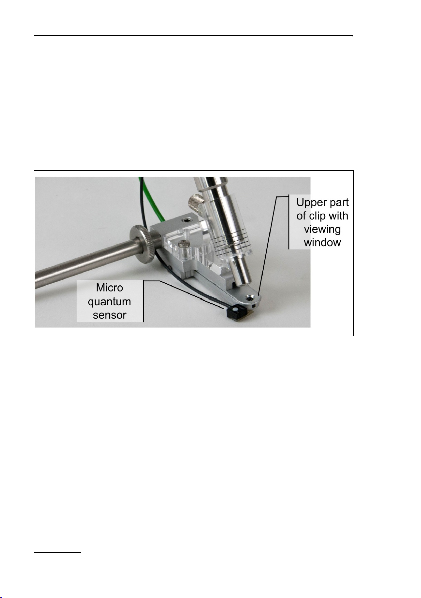
4.4.3 2060-B Arabidopsis Leaf Clip
This leaf clip is designed to position small samples in the beam
of the fiberoptics of the MINI-PAM-II. Usually, the 2060-B clip is
combined with the 2065-M Mini Quantum/Temp.-Sensor to
measure PAR at sample level and lower leaf temperature (see
Fig. 7, page 18).
7: 2060-B Arabidopsis Leaf Clip & 2065-M Mini Quantum/Temp.-Sensor
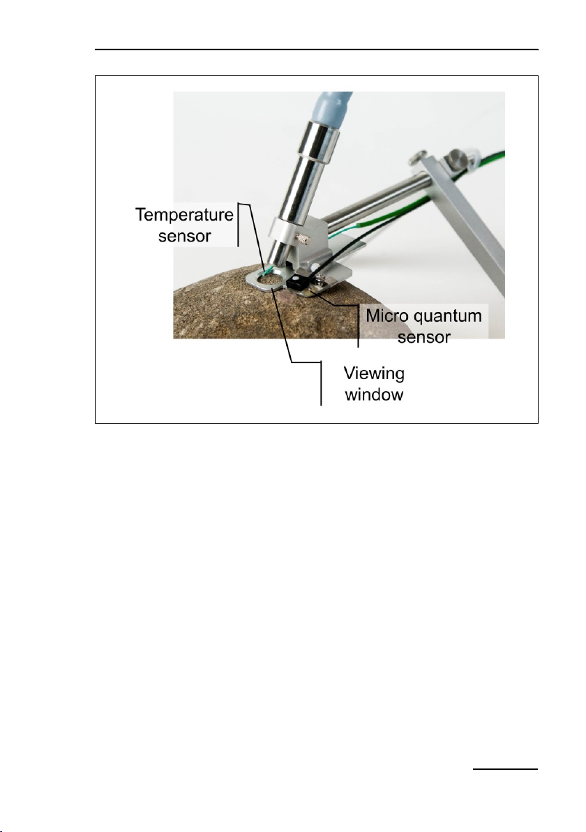
4.4.4 2060-A Fiberoptics Holder for Surfaces
The holder positions the fiberoptics of the MINI-PAM-II on bulky
samples. When combined with the 2065-M Mini Quantum/Temp.Sensor, temperature of and temperature and PAR impinging on
the surface area investigated can be measured (see Fig. 8, page
19).
Components and Setup Chapter 4
Fig.
8: 2060-A Fiberoptics Holder for Surfaces & 2065-M Mini Quan-
tum/Temp.-Sensor
4.4.5 2065-M Mini Quantum/Temp.-Sensor
The light and temperature sensors of the 2065-M device can be
mounted on the 2060-B Arabidopsis Leaf Clip and the 2060-A
Fiberoptics Holder for Surfaces. Both sensors of the 2065-M and
its amplifier unit are identical to the 2035-B (Section 4.4.1, page
13).
19
Chapter 4 Components and Setup
20
Fig.
9: Mini Quantum/Temp.-Sensor 2065-M
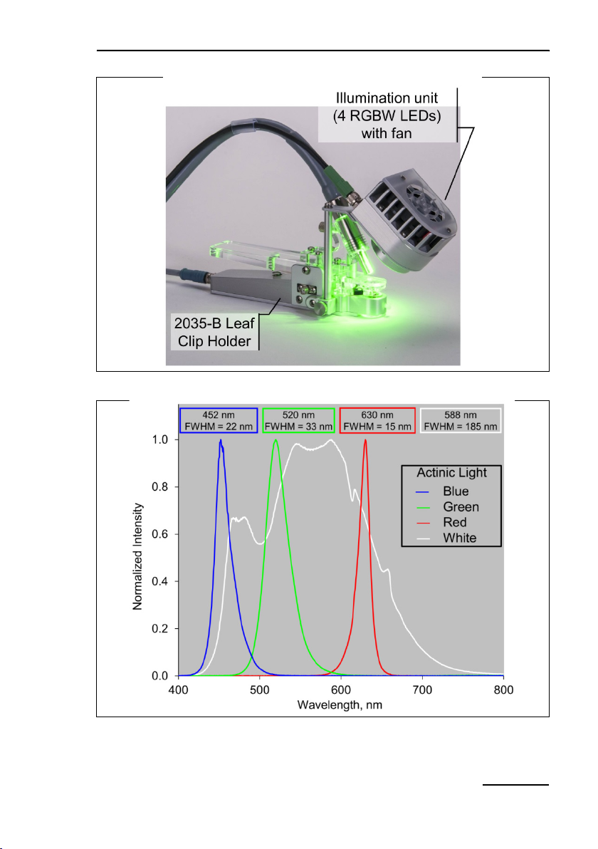
4.4.6 2054-L External LED Source
For experiments requiring different actinic light colors, we offer
an external light source which can be attached to the 2035-B leaf
clip (Fig. 10, page 21). The light source consists of four four-chip
LED RGBW sources each capable of emitting red, green, blue
and white light. Total intensity and color composition can be regulated by the software of the MINI-PAM-II or by WinControl-3.
The maximum PAR of each light quality is 1500 µmol m
-2 s-1
.
Note Switch off MINI-PAM-II before connecting of disconnection
2054-L External LED Source.
Components and Setup Chapter 4
Fig.
Fig.
Typical emission spectra normalized to unity of red, green, blue and
10: 2054-L External LED Source
11:
white light of the 2054-L External LED Source
21

Chapter 4 Components and Setup
22
Fig.
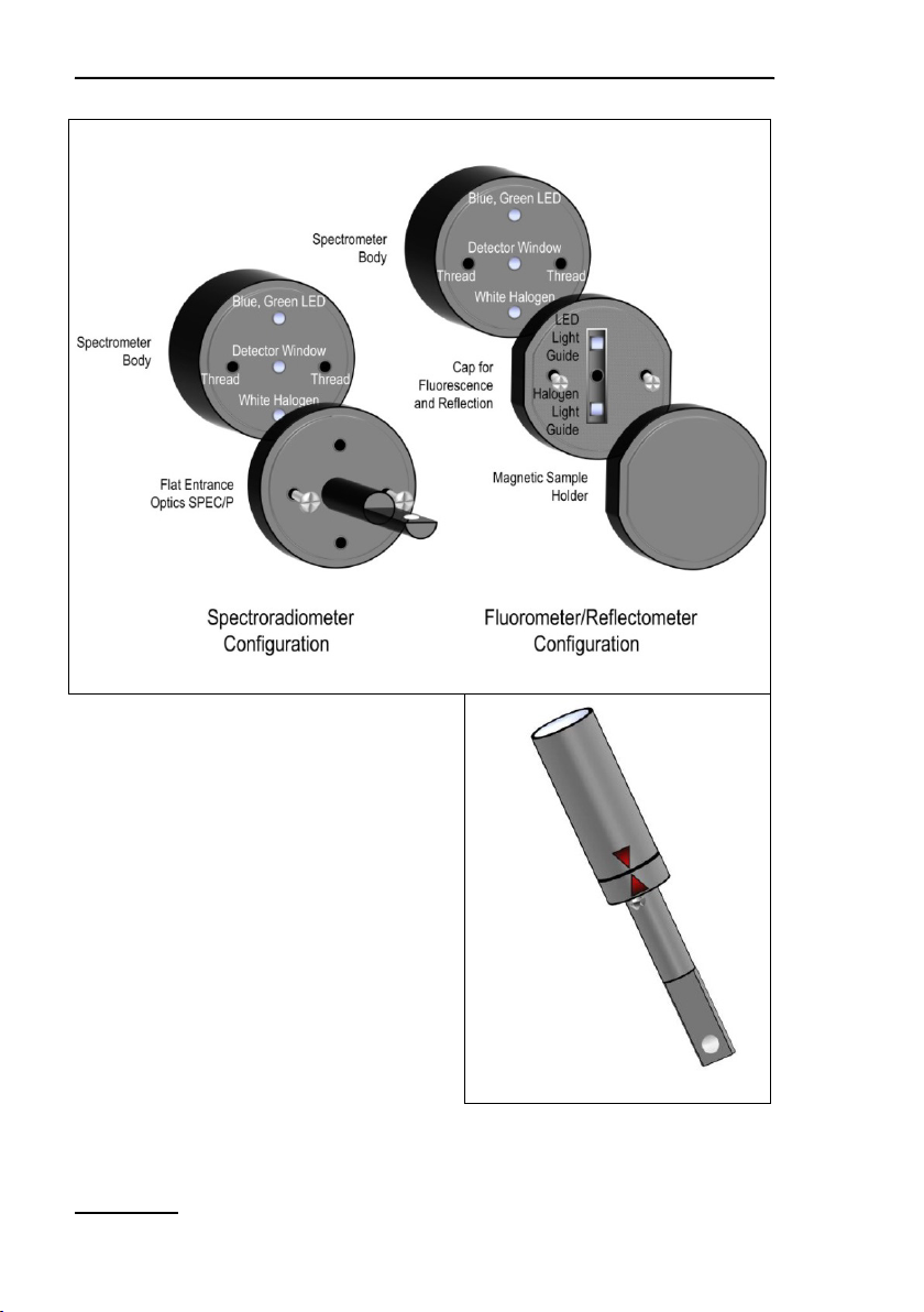
4.4.7 MINI-SPEC/MP Miniature Spectrometer
Originally, the spectrometer MINI-SPEC/MP (Fig. 15, page 25)
has been introduced as accessory for the DIVING-PAM-II. For
this reason, the MINI-SPEC/MP possesses an underwater-type
connector. Proper connection to the MINI-PAM-II requires that
the cable plug is completely inserted before the screw is tightened (see Fig. 12).
The spectrometer is calibrated to measure spectra of quantum
fluxes. Integration of these spectra over the visible range (400 –
700 nm) yields PAR data equivalent to those recorded by Walz
quantum sensors.
Like the PAR sensor of the 2035-B or 2065-M devices (Section
4.4.1, page 13 and Section 4.4.4, page 18), the spectrometer
12: Connection of MINI-SPEC/MP

Components and Setup Chapter 4
Fig.
can be employed to calibrate the internal PAR sensor of the
MINI-PAM-II (see Section 7.3.4.1, page 86). To this aim, the
MINI-PAM-II light guide and the entrance optics of the spectrometer are inserted in the PAR calibration block (Fig. 13, page 23).
The light guide can be inserted either in the 60° or the 90° port
according to the two possible orientations of the light guide in the
Leaf Clip Holder 2035-B. With both pieces fully inserted, the distance between fiber optics end and diffusing disk of the spectrometer matches the corresponding standard distances between
fiber optics end and sample level in the Leaf Clip Holder 2035-B.
Replacing the entrance optics used for evaluation of light by the
cap for fluorescence and reflection (Fig. 14, page 24) considerably extents the range of spectral information attainable by the
miniature spectrometer.
13: PAR Calibration Block
23
Chapter 4 Components and Setup
24
A
SPEC/MP: Configuration
B
A: Configurations of the Miniature
Fig. 14: Miniature Spectrometer MINI-
Spectrometer. B: Proper alignment of
parts for spectrometer configuration
using marker triangles
 Loading...