

Walz MINI-PAM User Manual

PHOTOSYNTHESIS YIELD
ANALYZER MINI-PAM
Portable Chlorophyll Fluorometer
Handbook of Operation
2.115 / 04.96
2. Edition: August 1999
minip_1ea.doc
Heinz Walz GmbH, 1999
Heinz Walz GmbH • Eichenring 6 • 91090 Effeltrich • Germany
Phone +49-(0)9133/7765-0 • Telefax +49-(0)9133/5395
E-mail info@walz.com • Internet www.walz.com
Printed in Germany


CONTENTS
1 Safety instructions ........................................................................ 1
1.1 General safety instructions ........................................................1
1.2 Special safety instructions.........................................................1
2 General Information .................................................................... 2
3 Basic Operation of the MINI-PAM............................................. 4
4 Description of the eight Keyboard Functions ............................ 7
4.1 Single key operations ................................................................ 7
4.2 Double key operations............................................................... 8
5 Important Points for Correct YIELD-Measurements ............ 10
6 Description of the Memory-Function ....................................... 12
7 The Mode-Menu ......................................................................... 14
7.1 List of Menu points ................................................................. 15
7.2 Description of the Mode-menu points.....................................17
8 Components of the MINI-PAM................................................. 29
8.1 Main Control Unit ...................................................................29
8.1.1 Fluorescence excitation and detection ..............................30
8.1.2 Special information on MINI-PAM/B .............................. 31
8.1.3 Internal halogen lamp as actinic light source....................33
8.1.4 Rechargeable battery......................................................... 34
8.1.5 LC-display......................................................................... 35
8.1.6 Electronic components...................................................... 36
8.1.7 Description of the connectors ...........................................37
8.2 Fiberoptics MINI-PAM/F and Miniature Fiberoptics
MINI-PAM/F1 ........................................................................38
8.3 Leaf-Clip Holder 2030-B ........................................................41
8.4 Micro Quantum/Temp.-Sensor 2060-M.................................. 45
8.5 External Halogen Lamp 2050-HB........................................... 45
8.6 Dark Leaf Clip DLC-8 ............................................................47
I

CONTENTS
9 Data Transfer.............................................................................. 48
10 Operation of the MINI-PAM via a PC-Terminal and the
RS 232 Interface ......................................................................... 51
11 Maintenance................................................................................ 53
11.1 Internal battery and its replacement ........................................ 53
11.2 Halogen lamp and its replacement ..........................................54
11.3 Fuse replacement..................................................................... 55
11.4 EPROM and its replacement ................................................... 55
12 Chlorophyll Fluorescence Measurements with the
MINI-PAM.................................................................................. 57
12.1 Chlorophyl fluorescence as an indicator of photosynthesis ....58
12.2 The PAM measuring principle ................................................64
12.3 Assessment of photosynthesis with the MINI-PAM: Outline
of the most important functions in practical applications. ......67
12.3.1 Maximal photochemical yield Fv/Fm ............................... 67
12.3.2 ML-BURST (menu point 5).............................................. 68
12.3.3 AUTO-ZERO (menu point 2) ........................................... 69
12.3.4 Fo, Fm (menu point 25) ....................................................70
12.3.5 INT.TEMP (menu point 35).............................................. 71
12.3.6 qP, qN and NPQ (menu points 26 and 27)........................ 73
12.3.7 YIELD-measurements of illuminated samples .................75
12.3.8 ACT-LIGHT and ACT+YIELD (menu points 12 and 13) 76
12.3.9 LIGHT CURVE (menu point 17) and LIGHT-
CURVE+REC (menu point 18) ........................................79
12.3.10 YIELD- and ETR-averaging (menu point 11) .................. 82
12.3.11 INDUCTION CURVE (menu point 21) and
INDUCTION CURVE+RECOVERY (menu point 22).... 83
12.3.12 Repetition Clock (menu point 28: REP-CLOCK and
double key function ON+MEM)....................................... 85
II

CONTENTS
13 Appendix ..................................................................................... 87
13.1 Technical specifications ..........................................................87
13.2 List of warnings and errors...................................................... 91
13.3 PIN-assignments...................................................................... 93
13.4 List of commands for operation of MINI-PAM via
PC-terminal by user-written software .....................................94
13.5 Selected reviews on chlorophyll fluorescence and related
topics ....................................................................................... 98
14 Rechargeable battery ............................................................... 104
15 Warranty conditions ................................................................ 105
III


CHAPTER 1 SAFETY INSTRUCTIONS
1 Safety instructions
1.1 General safety instructions
1. Read the safety instructions and the operating instructions first.
2. Pay attention to all the safety warnings.
3. Keep the device away from water or high moisture areas.
4. Keep the device away from dust, sand and dirt.
5. Always ensure there is sufficient ventilation.
6. Do not put the device anywhere near sources of heat.
7. Connect the device only to the power source indicated in the
operating instructions or on the device.
8. Clean the device only according to the manufacturer’s
recommendations.
9. Ensure that no liquids or other foreign bodies can find their way
inside the device.
10. The device should only be repaired by qualified personnel.
1.2 Special safety instructions
1. The MINI-PAM Photosynthesis Yield Analyzer is a highly
sensitive research instrument which should be used only for
research purposes, as specified in this manual. Please follow the
instructions of this manual in order to avoid potential harm to the
user and damage to the instrument.
2. The MINI-PAM employs high intensity light sources which may
cause damage to the eye. Avoid looking directly into these light
sources during continuous illumination or saturation pulses.
1

CHAPTER 2 GENERAL INFORMATION
2 General Information
The Photosynthesis Yield Analyzer MINI-PAM has been
developed with special attention to the quick and reliable assessment
of the effective quantum yield of photochemical energy conversion
in photosynthesis. The most relevant information is obtained by a
single key operation within a second and up to 4000 data sets can be
stored for later analysis. Due to a novel opto-electronic design and
modern microprocessor technology, the MINI-PAM is extremely
compact and at the same time highly sensitive and selective. It is
ideally suited for rapid screening of photosynthetic activity in the
field, green house and laboratory and due to its robust, waterproof
housing it can be used even in extreme environments.
The MINI-PAM, like all PAM Fluorometers, applies pulsemodulated measuring light for selective detection of chlorophyll
fluorescence yield. The actual measurement of the photosynthetic
yield is carried out by application of just one saturating light pulse
which briefly suppresses photochemical yield to zero and induces
maximal fluorescence yield. The given photochemical yield then
immediately is calculated, displayed and stored. Numerous studies
with the previously introduced PAM Fluorometers have proven a
close correlation between the thus determined YIELD-parameter
(∆F/Fm') and the effective quantum yield of photosynthesis in leaves,
algae and isolated chloroplasts. With the help of the optional LeafClip Holder 2030-B also the photosynthetic active radiation (PAR)
can be determined at the site of fluorescence measurement, such that
an apparent electron transport rate (ETR) is calculated. In addition to
this central information, the MINI-PAM also provides the possibility
of measuring fluorescence quenching coefficients (qP, qN, NPQ),
applying continuous actinic light for measurement of induction
curves (Kautsky-effect) and automatic recordings of light-saturation
2

CHAPTER 2 GENERAL INFORMATION
curves with quenching analysis. For these purposes, an extensive
MODE-menu is provided.
While the MINI-PAM was conceived as a typical stand-alone
instrument for field experiments, it can also be operated under
laboratory conditions in conjunction with a PC and the special
Windows-software WinControl. When the MINI-PAM is connected
to a PC, the information on instrument settings and data registration
is continuously exchanged, such that both ways of operation are
equivalent.
The WinControl software provides so-called "tooltips" with short
explanations of the numerous functions of the MINI-PAM. Hence,
use of WinControl is recommended particularly to the beginner for
becoming acquainted with the principles of operation and of
chlorophyll fluorescence information. It should be emphasized that
there is no risk of serious mistakes causing damage. Hence,
beginners may feel free to "play" with the system, trying out all
functions. For this purpose, the Chart-window is particularly useful,
as it records all fluorescence changes like a chart recorder.
This manual deals mainly with the MINI-PAM as such, operated
as a stand alone unit. A separate manual will be provided for the
WinControl software.
3

CHAPTER 3 BASIC OPERATION OF THE MINI-PAM
3 Basic Operation of the MINI-PAM
The MINI-PAM is very easy to operate. It has a two-line LCdisplay and a small tactile keyboard with eight function keys (ON,
OFF, MODE, MEM, ∧, ∨, START, SET). In order to get started, only
the fiberoptics have to be connected and the ON-key is pressed. Now
the system is ready for recording fluorescence yield of any sample
which is close (5-20 mm) to the free end of the fiberoptics. The
actual measurement of the most relevant YIELD-parameter (quantum
yield of photochemical energy conversion) just involves pressing the
START-key. Then on the display, for example, the following
information is shown:
1: 445F 1739M ..C
F: 448 745Y ..E ..L
The meaning of the various displayed parameters is as follows:
1: Number denoting the standard MODE-menu position 1
which is automatically installed whenever the MINI-PAM
is switched on or a YIELD-determination is carried out
via START.
445F Fluorescence yield (F) measured briefly before the last
saturating light pulse triggered by START.
1739M Maximal fluorescence yield (M = Fm or Fm') measured
during the last saturating light pulse triggered by START.
..C Temperature in degree Celsius, display of which requires
optional Leaf-Clip Holder 2030-B.
F: 448 Momentary fluorescence yield displaying small
fluctuations.
4

CHAPTER 3 BASIC OPERATION OF THE MINI-PAM
745Y The most relevant YIELD-parameter determined by the
last saturating light pulse triggered by START, calculated
as follows:
YIELD = Y/1000 = (M-F)/M = ∆F/M = ∆F/Fm'
(Genty-parameter)
With a dark-adapted sample ∆F/Fm = Fv/Fm,
corresponding to the maximal yield of photochemical
energy conversion.
..E Relative rate of electron transport (ETR), display of
which requires optional Leaf-Clip Holder 2030-B. It is
calculated by the formula:
ETR = E = YIELD x PAR x 0.5 x ETR-factor
..L Light intensity in terms of PAR (quantum flux density of
photosynthetically active radiation), display of which
requires Leaf-Clip Holder 2030-B.
After every operation of START the obtained data set with the
corresponding time and date is entered into a RAM-memory, with a
storage capacity of 4000 data sets. The stored data can be called on
the display via the MEM-key. Previously recorded data can be
recalled by using the arrow-keys (∧ or ∨). Stored data can be printed
out via an RS 232 interface or transferred on a PC for further
analysis.
The MINI-PAM has been pre-programmed at the factory with
standard settings
(see list in 7.1) for all relevant measuring
parameters (for example Measuring Light Intensity, Gain, Damping,
Saturation Pulse Intensity, Saturation Pulse Width etc.). These
standard settings are optimized for measurements with standard leaf
samples at approx. 12 mm distance between fiberoptics and leaf
surface. For special applications, there is great flexibility for
appropriate adjustment of all measuring parameters with the help of
the extensive MODE-menu, using the arrow-keys (∧ and ∨) in
5

CHAPTER 3 BASIC OPERATION OF THE MINI-PAM
combination with the SET-key. Details are given in the MODE-menu
list (see 7.2).
6
CHAPTER 4 DESCRIPTION OF KEYBOARD FUNCTIONS
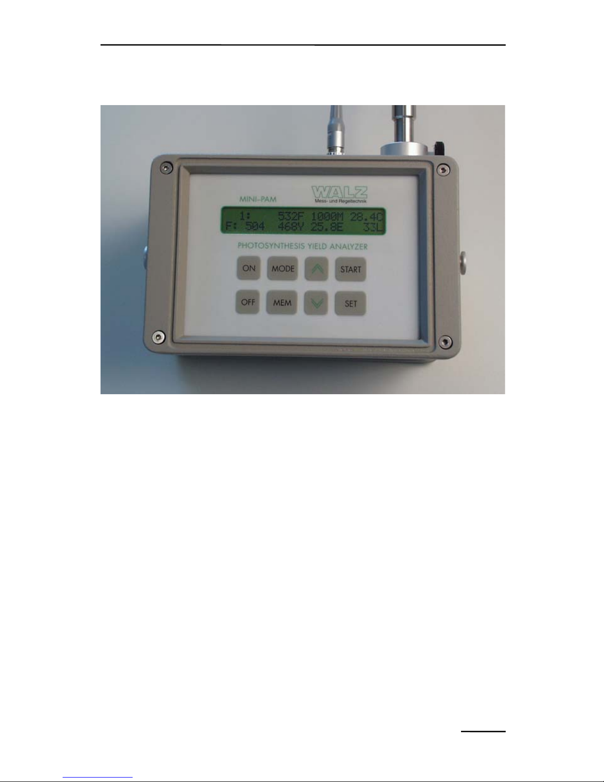
4 Description of the eight Keyboard Functions
Fig. 1: Photosynthesis Yield Analyzer MINI-PAM
4.1 Single key operations
ON To switch MINI-PAM on (short pressing of the key).
To activate the backlighting of the display (switches
automatically off when no key operation for 50 s; power
saving for field use); requires 3 s pressing of the key.
OFF To switch MINI-PAM off; will occur automatically, if no
key operation for 4 min (power saving for field use), unless
disabled via menu point 10.
MODE To return to MODE-menu after using the MEM- or SET-
keys.
7

CHAPTER 4 DESCRIPTION OF KEYBOARD FUNCTIONS
MEM To enter the MEMORY-level of stored data with the last
stored data set being displayed.
∧, ∨ To select one of 51 points of the MODE-menu or one of
4000 data sets when MEMORY is activated:
To change a particular parameter setting in the MODE-
menu after operating the SET-key.
For advancement by several steps these keys can be kept
pressed.
START To trigger a saturating light pulse for assessment of YIELD
and related fluorescence parameters.
SET To start and stop selected function.
4.2 Double key operations
Besides the single key operations, there is a number of double
key operations which can serve as short-cuts for selecting/carrying
out certain items/commands in the MODE-menu. For this purpose,
the first key must be kept firmly pressed before briefly pressing the
second key.
MODE+START To return to standard display (menu position 1).
MODE+SET To move from one functional block in the MODE-
menu to the next (see list in 7.1).
MODE+∧ To move to MODE-menu point 17: LIGHT CURVE
(carried out via SET).
MODE+∨ To move to MODE-menu point 21: IND.CURVE.
MODE+ON To switch measuring light on/off.
MODE+MEM To move to MODE-menu point 28: REP-CLOCK.
8

CHAPTER 4 DESCRIPTION OF KEYBOARD FUNCTIONS
ON+SET To switch actinic light on/off.
ON+START To start/stop actinic illumination with yield-
measurement (see menu point 13).
ON+MEM To start/stop the clock for repetitive triggering of
selected function (e.g. saturation pulses when 29:
CLOCK-ITEM in position SAT).
ON+∧ To start/stop a LIGHT CURVE (equivalent to menu
point 17).
ON+∨ To start/stop an INDUCTION CURVE (equivalent to
menu point 21).
SET+OFF To reset program, if MINI-PAM for some reason
does not respond to key-operations.
If the MINI-PAM is switched on by RS 232-access the keycontroller may not respond. In this case push the ON-key once.
Note:Whenever a command is given which involves the switching
on and off of the actinic halogen light source, a short beepsound confirms that the command is carried out. In addition,
there is a more extended beep for the duration of a saturating
light pulse.
9

CHAPTER 5 IMPORTANT POINTS
5 Important Points for Correct YIELD-
Measurements
The main purpose of the MINI-PAM is the reliable determination
of the YIELD-parameter ∆F/Fm (Genty-parameter). This task is
carried out by the MINI-PAM with exceptional sensitivity and
reproducibility. Because of the central importance of this particular
type of measurement, a special section is devoted to it in this
handbook (see section 12.3). Here just the most important practical
aspects are outlined which are essential for correct YIELDmeasurements:
1) The distance between sample and fiberoptics should be approx.
10-15 mm, such that a normal leaf at standard settings gives a
signal of 200-500 units.
2) The AUTO-ZERO function (MODE-menu point 2) should be
applied (while sample is removed), in order to suppress any
unavoidable background signal which otherwise would cause
some lowering of the YIELD-reading (see 12.3.3).
3) In practice, YIELD-measurements make sense only, if the light
conditions of the sample are well controlled. For example, a leaf
may be severely damaged in Calvin cycle activity and still show a
high YIELD-value when dark-adapted or in weak light. The
overall
photosynthetic performance should be assessed during
steady state illumination at a photon flux density which is
somewhat below saturation in a control sample. For highest
accurracy it is essential that the PAR is measured close to the spot
of the sample where also fluorescence is detected. For this
purpose the optional Leaf-Clip Holder 2030-B is available (see
8.3). On the basis of the measured YIELD- and PAR-data an
apparent electron transport rate (ETR) is calculated and displayed
10

CHAPTER 5 IMPORTANT POINTS
(...E). The plot of ETR vs. PAR corresponds to a light-response
curve of photosynthesis (see 12.3.9).
4) When YIELD is measured under field conditions, it is essential
that the leaf position and effective PAR are not inadvertently
changed. During the actual measurement, the fiberoptics must be
stably fixed with respect to the leaf surface for ca. 2 s, e.g. with
the help of the Leaf-Clip Holder 2030-B.
5) Dark YIELD-measurements require special conditions (see also
12.3.1). As already pointed out in 3), such measurements cannot
give information on the overall
photosynthetic performance. They
are useful to specifically assess the state of PS II, for example
following light stress treatment. In this case, it is essential, that
the measuring light does not induce any significant increase of
fluorescence yield. For this purpose, the MODE-menu point 5
provides the possibility of applying the measuring light in short
pulse bursts, thus cutting its integrated intensity to 1/5 (see
12.3.2).
11

CHAPTER 6 DESCRIPTION OF THE MEMORY-FUNCTION
6 Description of the Memory-Function
All data recorded via START are automatically stored in RAMmemory with a capacity of 4000 data sets. They can be recalled on
display via the MEM-key. Then, for example, the following
information is shown:
MEM 382: 12:27 27/MAY/95
A: 322Y 21.1E 157L
In the top line it can be seen that the data set Nr. 382 of the
current MEMORY was recorded at 12:27 o'clock on May 27th 1995.
The bottom line shows that a sample of type A was used (see
MODE-menu point 51), which displayed a YIELD-value (Y) of
0.322 and an apparent ETR-value (E) of 21.1 at an incident light
intensity (L) of 157 µmol quanta m
-2 s-1
of the photosynthetically
active radiation (PAR).
More information relating to this particular data set can be
displayed in the top line by SET-operation:
MEM 382:390F 576M 19.9C
A: 322Y 21.1E 157L
After the first SET, the top line shows that the fluorescence yield
(F) measured briefly before the saturating light pulse was 390, that
the maximal fluorescence (M) amounted to 576 and that temperature
was 19.9 °C.
MEM 382:645P 759N 1.557Q
A: 322Y 21.1E 157L
After the second SET, the top line shows the quenching
coefficients qP=0.654, qN=0.759 and NPQ=1.557, which will be
meaningful only if for this particular sample a Fo-Fm determination
12

CHAPTER 6 DESCRIPTION OF THE MEMORY-FUNCTION
(MODE-menu point 25) had been carried out beforehand (see
12.3.4).
Further operation of SET (2x) leads back to the original display
with time and date.
Using the arrow keys ∧ and ∨ one can move within the memory
and display any previously recorded data sets.
All data stored in MEMORY can be cleared by the CLEAR
MEMORY function (MODE-menu point 39). For safety's sake, this
command does not only require execution by SET, but in addition
confirmation by the ∧-key. The memory is organized in form of a
ring storage and its clearance normally is not required, as old data
will be automatically overwritten.
The MEMORY-front normally corresponds to the MEM-No.
under which the last set of data was stored. It can be moved to any
number between 1 and 4000 with the help of MODE-menu point 38.
After any change in instrumental settings, the complete set of
settings will be stored upon the next YIELD-measurement in the
Report-file of the WinControl program (see separate manual). This is
indicated by "Saved Settings" in the MEMORY-display.
Data stored in MEMORY can be readily transferred to a PC via
the RS 232 cable (see section 9).
13

CHAPTER 7 THE MODE-MENU
7 The Mode-Menu
The MODE-menu contains 51 items corresponding to a variety
of measured values, instrumental settings or special commands. The
positions of the various menu points were arranged for optimal
practicability, with the most frequently used functions being closest
to the standard position 1.
Increasing or decreasing position numbers are selected by the ∧-
or ∨-arrow keys, respectively. Changes are terminated via SET or
MODE. Starting from position 1, at increasing numbers there are
mostly MODE-points involving commands (for example, 2: AUTOZERO), while at decreasing numbers the MODE-points for
instrumental settings prevail (for example, 50: MEASURING
LIGHT INTENSITY). Some of the MODE-menu positions can be
directly reached via double key operations (see list in section 4.2
above).
Irrespective of the selected menu position, a YIELDmeasurement can be initiated at any time by pressing the START-key.
Normally, the system then automatically returns to the menu position
1 where the measured data set is displayed. The only exceptions are
menu-positions 11, 25-27 and 34, where the displayed values are of
primary interest.
The operations related to the various points of the MODE-menu
are either directly carried out via SET (e.g. 2: AUTO-ZERO: 50) or
initiated/terminated (e.g. 50: MEAS-INT: 8) by pressing SET.
Settings are changed by arrow key operations (∧, ∨) and become
immediately effective. The numbers following the double points
show the present settings.
14

CHAPTER 7 THE MODE-MENU
7.1 List of Menu points
The Menu points are organized in functional blocks. The starting
point of each block can be reached successively by simultaneous
pressing of MODE and SET. The frequently used positions MARK,
MEAS-INT and GAIN can be readily selected by going backwards
from position 1 using the ∨-key.
The below list shows the default settings, which can be reset at
any time by the command 36: RES. SETTINGS. The first points of
the functional blocks which can be quickly reached by the
MODE+SET command, are emphasized by boldface printing. The
double-key commands by which some of the menu points can be
quickly accessed are also listed.
Menu points: Quick access via:
1. Standard display MODE+START
2. AUTO-ZERO: 0(SET)
3. MEAS.LIGHT: ON (SET) MODE+ON
4. M.FREQ: LOW (SET)
5. ML-BURST: OFF(SET)
6. LIGHT AV15s:OFF(SET)
7. EXT.LIGHT-S:ON (SET)
8. LIGHT CALIB: (SET)
9. DISP.ILLUM.:OFF(SET)
10. AUTO-OFF: ON (SET)
11. AV. YIELD and ETR
12. ACT-LIGHT: OFF(SET)
13. ACT+YIELD: OFF(SET)
14. ACT-WIDTH 0:30 (SET)
15. ACT-INT: 5 (SET)
16. AL-FACT: 1:00 (SET)
17. LIGHT CURVE:OFF(SET) MODE+∧
15

CHAPTER 7 THE MODE-MENU
18. L.CURVE+REC:OFF(SET)
19. LC-WIDTH 0:10 (SET)
20. LC-INT: 3 (SET)
21. IND.CURVE: OFF(SET) MODE+∨
22. IND.C+REC: OFF(SET)
23. IND-DELAY 0:40 (SET)
24. IND-WIDTH 0:20 (SET)
25. Fo and Fm (SET)
26. qP and qN (SET)
27. NPQ (SET)
28. REP-CLOCK: OFF(SET) MODE+MEM
29. CLOCK-ITEM:SAT(SET)
30. CLK-TIME:00:30(SET)
31. TIME 17:32:56 (SET)
32. DATE 17-OCT (SET)
33. YEAR 1997 (SET)
34. BATT: 12.4V (11.8)
35. INT.TEMP: 23C
36. RES.SETTINGS: (SET)
37. PROGR.D2.07(280698)
38. MEMORY: 12 (SET)
39. CLEAR MEMORY (SET)
40. LIGHT-OFFS: 0(SET)
41. LIGHT-GAIN:1.00(SET)
42. TEMP.OFFS: 0.0(SET)
43. TEMP.GAIN: 1.00(SET)
44. ZERO-OFFS: 20(SET)
45. ETR-FAC: 0.84 (SET)
46. SAT-WIDTH:0.8s(SET)
47. SAT-INT: 8 (SET)
48. DAMP: 2 (SET)
16

CHAPTER 7 THE MODE-MENU
49. GAIN: 2 (SET)
50. MEAS-INT: 8 (SET)
51. MARK: A (SET)
7.2 Description of the Mode-menu points
The following list briefly describes the items contained in the
MODE-menu, some of which are outlined in more detail in section
12.3 (Assessment of photosynthesis yield with the MINI-PAM).
Standard settings are shown.
Standard menu-position for display of the
data measured by last saturating light pulse
triggered by START. The 4 central parameters F, M, Y and E, the
present fluorescence signal F: (with blinking *), temperature (°C)
and and ambient PAR (L) are displayed.
1: 445F 1739M 19.9C
F: 448 745Y 6.2E 20L
Command for determination of signal in
absence of sample (background signal), the
value of which is displayed and automatically subtracted, such that
signal becomes zero without sample. This offset value remains
effective for all following measurements until being deliberately
changed. It has to be newly determined whenever 50: MEASURING
LIGHT INTENSITY or 49: GAIN are modified. If this is not done
there is a warning ?NEW OFFSET? when YIELD is determined by
START. The warning will stop when a new offset is determined via
menu point 2 or the given offset is confirmed in menu position 1 via
SET.
2: AUTO-ZERO: 20(SET)
F: 448 745Y 6.2E 20L
On/off switch of measuring light. Under
standard conditions the measuring light is
on. When switched off, a negative signal indicates the AUTO-ZERO
value (see menu point 2). The switch can also be operated via
MODE + ON without entering the MODE-menu.
3:MEAS.LIGHT: ON (SET)
F: 448 745Y 6.2E 20L
17

CHAPTER 7 THE MODE-MENU
Switch between the standard measuring
pulse frequency of 0.6 kHz (LOW) and 20
kHz (HIGH). At 20 kHz the signal/noise is increased by a factor
of 5-6. On the other hand, at this high frequency the measuring light
intensity can induce substantial fluorescence changes. Hence, 20 kHz
normally should be used only when its actinic effect can be
neglected relative to a stronger ambient light (e.g. above 100 µmol
quanta m
-2 s-1
).
4: M.FREQ: LOW (SET)
F: 448 745Y 6.2E 20L
Switch between normal signal detection
(continuously pulsed measuring light) and
signal detection by short bursts of measuring light. In the latter case,
pulse trains are 0.2 s with dark-intervals of 0.8 s, resulting in a
reduction of integrated measuring light intensity by a factor of 5.
This can be advantageous for assessment of the maximal
photochemical yield after dark-adaptation (∆F/Fm = Fv/Fm). In the
ML-BURST mode the basic frequencies of 0.6 or 20 kHz are
maintained.
5: ML-BURST: OFF(SET)
F: 448 745Y 6.2E 20L
When this function is enabled, the readings
of the external light sensor are averaged
over a period of 15 s, in order to account for fluctuations of light
intensity. It is important that the sensor remains fixed in a given
position for 15 s before the actual measurement of quantum yield.
6:LIGHT AV15s:OFF(SET)
F: 448 745Y 6.2E 20L
Switch to enable display of external
LIGHT-SENSOR readings (in ONposition). When in OFF-position, the PAR-values stored in an
internal list are effective. This list is created via the LIGHT-CAL
function (see next menu point).
7:EXT.LIGHT-S:ON (SET)
F: 448 745Y 6.2E 20L
Automatized routine for determination of
PAR-values of the 12 ACTINIC LIGHT
Intensity settings in a given measuring geometry. These values are
stored in a list, which is effective whenever the EXT.LIGHT-
8:LIGHT-CALIB: (SET)
F: 448 745Y 6.2E 20L
18

CHAPTER 7 THE MODE-MENU
SENSOR is OFF (menu point 7). For this determination the LIGHTSENSOR must be fixed instead of the sample in front of the
fiberoptics. When the routine is carried out, the LIGHT
AVERAGING function (menu point 6) is disabled. If it is afterwards
required, it must be manually enabled. After the LIGHTCALIBRATION the EXT.LIGHT-SENSOR (menu point 7) is in the
OFF-position.
When in ON-position, the DISPLAY is
continuously illuminated. It should be
noted, that this may cause considerable costs of battery power. When
in OFF-position, DISPLAY ILLUMINATION can be transiently
turned on for 40 s by pressing ON for 3 s.
9: DISP.ILLUM:OFF(SET)
F: 448 745Y 6.2E 20L
On/off switch to enable/disable the power
saving automatics which turn off the
MINI-PAM after 4 min without key operation. It is advisable to
disable the AUTO-OFF when the MINI-PAM is connected to an
external power supply (via CHARGE-socket). Whenever the
instrument is switched off manually, the AUTO-OFF function is
enabled again (automatic reset to ON-position). The AUTO-OFF
function is also automatically enabled when battery voltage drops
below 11.2 V.
10: AUTO-OFF: ON (SET)
F: 448 745Y 6.2E 20L
Function to average a number of
consecutive YIELD- and ETR-determinations. The SET-key is used to reset the counter to 0 and to erase
the averaged values of the preceding measurements. For safety's sake
the reset must be confirmed by pressing the ∧-key. The averaged
YIELD and ETR are shown in the top line, whereas in the bottom
line the values of the last measurement are displayed.
11:AV. 564Y 5.9E 8No
F: 448 745Y 6.2E 20L
On/off switch of the internal actinic light
source (halogen lamp). This can also be
directly operated via ON + SET. The internal actinic lamp is not
12: ACT-LIGHT: OFF(SET)
F: 448 745Y 6.2E 20L
19

CHAPTER 7 THE MODE-MENU
meant to be turned on for extended periods of time, as this may lead
to excessive internal heating. Therefore, the illumination periods are
restricted (see menu point 14: ACT-WIDTH). There is a blinking
sign (ACT) in the upper left corner while actinic illumination is on.
On/off switch of the internal actinic light
source, with additional application of a
saturation light pulse for YIELD-assessment at the end of the
illumination time which is set by menu point 14: ACT-WIDTH.
There is a blinking sign (A+Y) in the upper left corner of the display
while actinic illumination with terminal YIELD-determination is
running. This function can be also directly started from standard
position 1 by double key operation ON + START.
13: ACT+YIELD: OFF(SET)
F: 448 745Y 6.2E 20L
Setting of actinic illumination time. The
setting can be modified via SET and the
arrow-keys in 10 s steps. Maximal setting is limited to 5 min (5:00)
in order to avoid excessive internal heating.
14:ACT-WIDTH 0:30 (SET)
F: 448 745Y 6.2E 20L
Setting of intensity of internal actinic light
source (halogen lamp). The setting can be
modified via SET and the arrow-keys between 0 and 12. The range
covered by intensities 1-12 can be shifted up and down with the help
of AL-FACT (menu point 16).
15: ACT-INT: 5 (SET)
F: 448 745Y 6.2E 20L
Actinic light factor by which the range of
actinic intensities (ACT-INT, menu point
15) can be shifted up and down. The standard factor of 1.00 can be
modified between 0.5 and 1.5 via SET and the arrow keys. The
relationship between AL-FACT and PAR is non-linear.
16: AL-FACT: 1.00 (SET)
F: 448 745Y 6.2E 20L
When switched on via SET, first the
maximal YIELD in the absence of actinic
light (Fv/Fm) is measured and then a series of 8 consecutive YIELDmeasurements at increasing light intensities is started. This function
17:LIGHT CURVE:OFF(SET)
F: 448 745Y 6.2E 20L
20

CHAPTER 7 THE MODE-MENU
can be also directly started by double key operation ON + ∧. The
time periods at the different intensities are set by menu point 19: LCWIDTH. There is a blinking sign (LC) in the upper left corner of the
display while a LIGHT CURVE is recorded. The series involves
YIELD-determinations at 8 settings of actinic light. It starts with the
intensity-setting, which is selected by 20: LC-INT, where one can
choose between values from ACT-INT 1 to 5, with the standard
setting being ACT-INT 3. The range of absolute PAR-values
corresponding to these settings can be moved up and down with the
help of menu point 16: AL-FACT or by changing the distance
between fiberoptics and sample. The effective PAR-values at the
sample surface may be calibrated by the LIGHT-CALIBRATION
routine (menu point 8). A LIGHT CURVE can provide profound
information on the overall photosynthetic performance of a plant,
even if the illumination periods are too short to achieve true steady
states. Note: Due to the unavoidable internal heating during
recording of a LIGHT CURVE, assessment of absolute
fluorescence
signal amplitudes is problematic, but this does not
affect correct
determination of the ratio ∆F/Fm'.
When switched on via SET, a LIGHT
CURVE is measured as described for menu
point 17 and in the following dark period the recovery of YIELD is
assessed by 6 consecutive measurements at 10 s, 30 s, 60 s, 2 min,
5 min and 10 min following illumination. Note: Due to the
unavoidable internal heating during recording of a LIGHT CURVE
assessment of absolute
fluorescence signal amplitudes is
problematic, but this does not
affect correct determination of the ratio
∆F/Fm'.
18:L.CURVE+REC:OFF(SET)
F: 448 745Y 6.2E 20L
LC-WIDTH determines the illumination
time at each intensity setting. 10 s are
19: LC-WIDTH 0:10 (SET)
F: 448 745Y 6.2E 20L
21

CHAPTER 7 THE MODE-MENU
sufficient for so-called "rapid light curves". It is limited to 3 min in
order to avoid excessive internal heating.
The LC-INT determines the starting
intensity which can be chosen between
settings 1 to 5. LIGHT CURVES always involve 8 intensities. Hence,
more emphasis may be put either on the linear rise or on the plateau
region of the curve.
20: LC-INT: 3 (SET)
F: 448 745Y 6.2E 20L
This function starts registration of a dark-
to-light INDUCTION CURVE with
Saturation Pulse Quenching Analysis. Normally dark-adapted
samples are used. First a saturation pulse is given for determination
of Fo, Fm and Fv/Fm. After a certain dark time, set by IND. DELAY
(menu point 23), ACTINIC LIGHT at a given intensity (ACT-INT,
menu point 15) is turned on and 8 saturation pulses are applied at
intervals determined by IND.WIDTH (menu point 24).
21: IND.CURVE: OFF(SET)
F: 448 745Y 6.2E 20L
In addition to the recording of dark-to-light
INDUCTION CURVE (as described for
menu point 21), after turning off the ACT.-LIGHT 6 saturation
pulses are applied at 10 s, 30 s, 60 s, 2 min, 5 min and 10 min to
assess the dark recovery of fluorescence parameters.
22: IND.C+REC: OFF(SET)
F: 448 745Y 6.2E 20L
Delay time between first saturation pulse
and turning-on of ACT-LIGHT. The
default setting is 40 s. Possible settings range from 5 s to 10 min.
23:IND-DELAY 0:40 (SET)
F: 448 745Y 6.2E 20L
Time interval between two consecutive
saturation pulses during recording of
IND.CURVE. The default setting is 20 s. Possible settings range
from 5 s to 3 min.
24:IND-WIDTH 0:20 (SET)
F: 448 745Y 6.2E 20L
Function to sample the minimal
25:Fo: 530 Fm:2650(SET)
F: 448 745Y 6.2E 20L
22

CHAPTER 7 THE MODE-MENU
fluorescence, Fo, and maximal fluorescence, Fm, of a dark-adapted
sample by use of the SET-key
. The thus sampled values are stored
until new values are sampled via SET
. With START a normal
YIELD-determination is carried out and the given Fo- and Fm-values
are maintained. The stored Fo- and Fm-values are used for
determination of the quenching coefficients qP, qN and NPQ (see
menu points 26 and 27). In some applications, in order to obtain
minimal Fo it is advantageous to make use of the ML-BURST
function (see menu point 5).
Coefficients of photochemical quenching,
qP, and non-photochemical quenching, qN,
as defined by the following equations:
26: qP:1000qN:000 (SET)
F: 448 745Y 6.2E 20L
qP=(M-F)/(M-Fo) and qN=(Fm-M)/(Fm-Fo)
In order to obtain the usual values between 0 and 1, the displayed
values have to be multiplied by 0.001. qP is set to 000 if M<F and
qN is set to 000 if M>Fm. qN is set to 1.000 if M<Fo.
Note: M here represents the maximal fluorescence measured by a
saturation pulse in any given light state (normally denoted Fm'),
whereas Fm and Fo are the particular values sampled via menu point
25 after dark-adaptation. The thus determined values of qP and qN
should be considered approximations only, as a possible nonphotochemical quenching of Fo is not taken into consideration.
Parameter describing non-photochemical
quenching defined by the equation:
27: NPQ:1.440 (SET)
F: 448 745Y 6.2E 20L
NPQ = (Fm-M)/M
Note: M here represents the maximal fluorescence measured by a
saturation pulse in any given light state (normally denoted Fm'),
whereas Fm is the particular value sampled via menu point 25 after
dark-adaptation. NPQ has been shown to be closely related to the
23

CHAPTER 7 THE MODE-MENU
excess light energy which is actively dissipated by plants into heat in
order to avoid photodamage. Contrary to qN, NPQ-determination
does not require knowledge of Fo and is not affected by nonphotochemical quenching of Fo. NPQ is set to 0.000 if M>Fm.
On/off switch of repetition clock which
serves to trigger a number of functions
which are specified in menu point 29: CLOCK ITEM. This function
can be also directly started by double key operation ON + MEM.
28: REP-CLOCK: OFF(SET)
F: 448 745Y 6.2E 20L
This menu point allows to choose between
the following functions to be triggered by
the REPETITION CLOCK:
29: CLOCK-ITEM:SAT(SET)
F: 448 745Y 6.2E 20L
SAT-PULSE, ACT-LIGHT, ACT + YIELD, LIGHT CURVE,
L-CURVE + REC., IND. CURVE , IND.C + REC.
Setting of clock interval, which is the time
between two consecutive saturation pulses
(or other functions) triggered by the REP-CLOCK (menu point 28).
The setting can be modified via SET and the arrow-keys in 10 s
steps. Possible settings range from 0:10 to 42:30. When moving
beyond the maximal time, the lowest values are reached and vice
versa.
30: CLK-TIME: 0:30(SET)
F: 448 745Y 6.2E 20L
Display of present time which can be
modified via SET and the arrow-keys.
With SET one can move from the hours to minutes and vice versa.
The change is terminated via MODE.
31: TIME 14:43:51 (SET)
F: 448 745Y 6.2E 20L
Display of present date which can be
modified via SET and the arrow-keys.
With SET one can move from the days to months and vice versa. The
change is terminated via MODE.
32: DATE 17-OCT (SET)
F: 448 745Y 6.2E 20L
Display of present year which can be
33: YEAR 1999 (SET)
F: 448 745Y 6.2E 20L
24
 Loading...