

Page 1
TESTO ITC KORINNA 28mmAllargato
MONOBLOCK DIRECTIONAL
CONTROL VALVE
Page 2

SD5
Features
Simple , compact and heavy duty designed monoblock valves from 1 to 7 sections for open and closed center hydraulic systems..
H Fitted with a main pressure relief valve and a load check valve.
H Available with parallel, series or tandem circuit.
H Optional power beyond port (only for parallel or tandem circuit).
H Diameter 16 mm -- 0.63 in interchangeable spools.
H A wide variety of service port valve options.
H Actuation is manual, pneumatic, electro --pneumatic, hydraulic, electro--hydraulic, with solenoid and remote with flexible cables
spool control kits.
Additional information
This catalog shows the product in the most standard configurations.
Please contact Customer Service Dpt. for more detailed information or
special request.
WARNING!
All specifications of this catalog refer to the standard product at this date.
Walvoil, oriented to a continuous improvement, reserves the right to
discontinue, modify or revise the specifications, without notice.
WALVOIL IS NOT RESPONSIBLE FOR ANY DAMAGE CAUSED BY AN
INCORRECT USE OF THE PRODUCT.
5thedition November 2002:
This edition supercedes all prior documents.
2 DAT003A
Page 3

SD5
Contents
Contents
Working conditions 4. . . . . . . . . . . . . . . . . . . . . . . . . . . . . . . . .
Dimensional data 5. . . . . . . . . . . . . . . . . . . . . . . . . . . . . . . . . . .
Hydraulic circuit 6. . . . . . . . . . . . . . . . . . . . . . . . . . . . . . . . . . . .
Performance data 7. . . . . . . . . . . . . . . . . . . . . . . . . . . . . . . . . .
Ordering codes 8. . . . . . . . . . . . . . . . . . . . . . . . . . . . . . . . . . . . .
Inlet relief options 10. . . . . . . . . . . . . . . . . . . . . . . . . . . . . . . . . .
Spool options 11. . . . . . . . . . . . . . . . . . . . . . . . . . . . . . . . . . . . .
“A” side spool positioners 18. . . . . . . . . . . . . . . . . . . . . . . . . .
“B” side options 30. . . . . . . . . . . . . . . . . . . . . . . . . . . . . . . . . . .
Complete control kits 34. . . . . . . . . . . . . . . . . . . . . . . . . . . . . . .
Outlet port options 40. . . . . . . . . . . . . . . . . . . . . . . . . . . . . . . . .
Service valves
ordering codes 42. . . . . . . . . . . . . . . . . . . . . . . . . . . . . . . . .
port relief valves 44. . . . . . . . . . . . . . . . . . . . . . . . . . . . . . . .
anti--shock valves 46. . . . . . . . . . . . . . . . . . . . . . . . . . . . . .
pilot operated check valves 47. . . . . . . . . . . . . . . . . . . . . .
anti--shock and anti--cavitation valves 49. . . . . . . . . . . . .
flow regulator valves 50. . . . . . . . . . . . . . . . . . . . . . . . . . . .
Other execution
monoblock valve SD5/1 --N 54. . . . . . . . . . . . . . . . . . . . . . .
monoblock valve SD5/1 --D 55. . . . . . . . . . . . . . . . . . . . . . .
monoblock valve SD5 --S with series circuit 56. . . . . . . . .
monoblock valve SD5 --S with tandem circuit 58. . . . . . . .
Installation and maintenance 60. . . . . . . . . . . . . . . . . . . . . . . .
Accessories 62. . . . . . . . . . . . . . . . . . . . . . . . . . . . . . . . . . . . . .
3DAT003A
Page 4
SD5
Working conditions
This catalog shows technical specifications and diagrams measured with mineral oil of 46 mm2/s -- 46 cSt viscosity at 40°C -- 104°F
temperature.
Nominal flow rating 45 l/min 12 US gpm
Operating pressure (maximum) parallel pr tandem circuit 315 bar 4600 psi
series circuit 250 bar 3600 psi
Max. back pressure on outlet port T 25 bar 360 psi
Internal leakage A(B)®T
Hydraulic fluid Mineral base oil
Fluid temperature range with NBR seals from --20° to 80°C from --4° to176°F
Viscosity operating range from 15 to 75 mm2/s from 15 to 75 cSt
Max. level of contamination 19/16 -- ISO 4406 NAS 1638 -- class10
Ambient temperature range from --40° to 60°C from --40° to 140°F
Dp=100 bar -- 1450psi
fluid and valve at 40°C -- 104°F
with FPM seals from --20° to 100°C from --4° to 212°F
minimum 12 mm2/s 12 cSt
maximum 400 mm2/s 400 cSt
3 cm3/min 0.18 in3/min
NOTE -- For different conditions please contact Customer Service.
4 DAT003A
Page 5
SD5
TYP
E
TYP
E
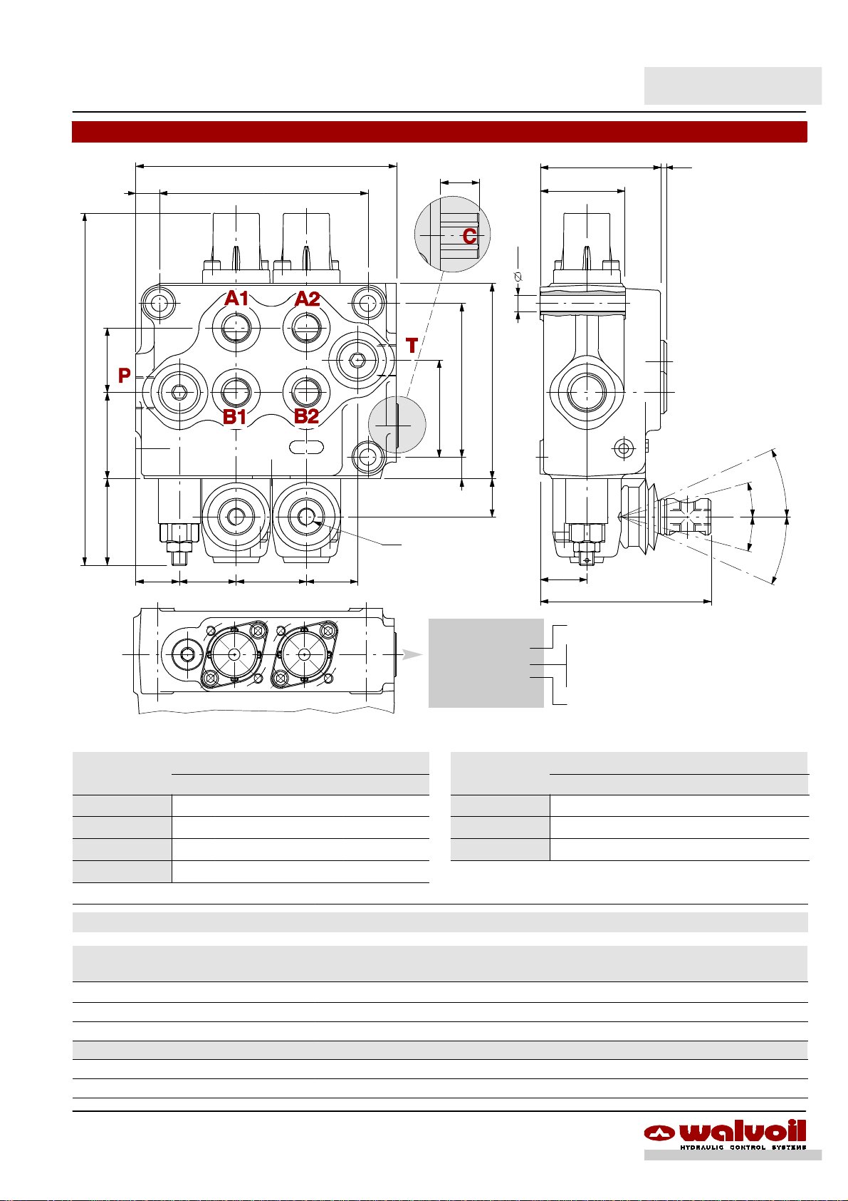
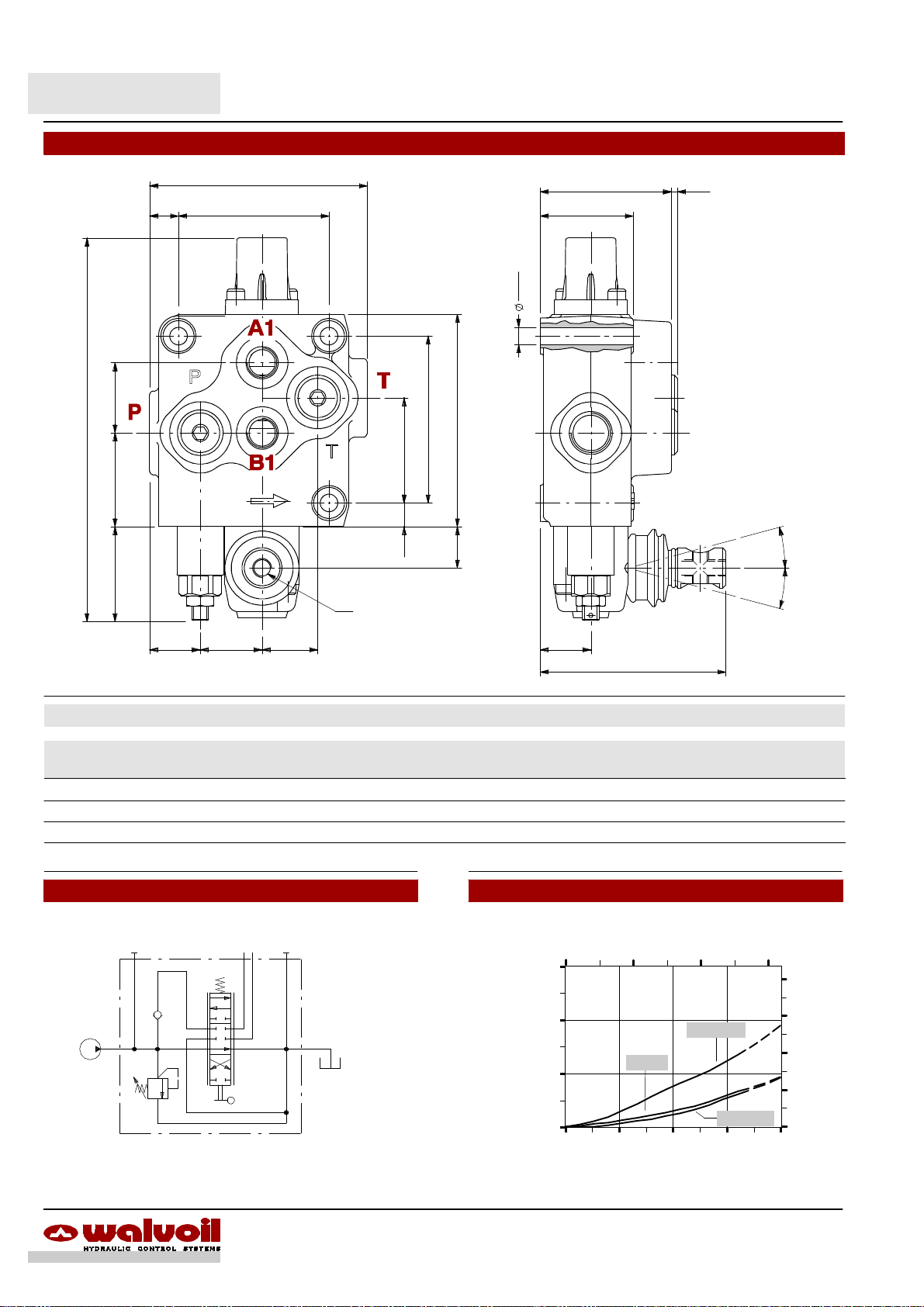
Dimensional data (parallel circuit)
E
12,5
0.06
34
1.34
186
7.32
45,5
1.791.77
45
F
Power beyond
M 8
63,5
21
0.81
8,5
0.33
81
103
4.06
3.19
51
2.01
2.50 0.12
45
1.77
3
spool out
3
11,5
0.45
20
0.79
1
24°
15°
0
15°
24°
2
23
0.91
30 37
1.18
1.46 1.06
27
WALVOIL
SD5/2--P
SD5/2--P
P0200001
WALVOIL
102219002
MADE IN ITALY
P0200001
102219002
24,5
0.96
90
3.54
Valve type
Production batch:
P02 = production year (2002)
00001 = progressive number
3
spool in
MADE IN ITALY
Valve code
SD5/1--P
SD5/2--P
SD5/3--P
SD5/4--P
E F Weight
mm in mm in kg lb
100.5 3.96 73 2.87 3.5 7.7
137.5 5.41 110 4.33 5.2 11.5
174.5 6.87 147 5.79 6.9 15.2
211.5 8.33 184 7.24 8.1 17.9
SD5/5--P
SD5/6--P
SD5/7--P
E F Weight
mm in mm in kg lb
248.5 9.78 221 8.70 10.1 22.3
285.5 11.24 258 10.16 11.7 25.8
322.5 12.70 295 11.61 13.2 29.1
Standard threads
PORTS
BSP
(ISO 228/1)
Inlet P and power beyond C G 3/8 3/4--16 UNF--2B (SAE 8) M18x1.5
A and B ports G 3/8 9/16 --18 UNF--2B (SAE 6) M18x1.5
Outlet T G 3/8 3/4--16 UNF--2B (SAE 8) M18x1.5
PILOT PORTS
Pneumatic NPTF 1/8--27 NPTF 1/8--27 NPTF 1/8--27
Hydraulic G 1/4 9/16--18 UNF--2B (SAE 6) G 1/4
5DAT003A
UN--UNF
(ISO 11926--1)
METRIC
(ISO 262)
Page 6
SD5
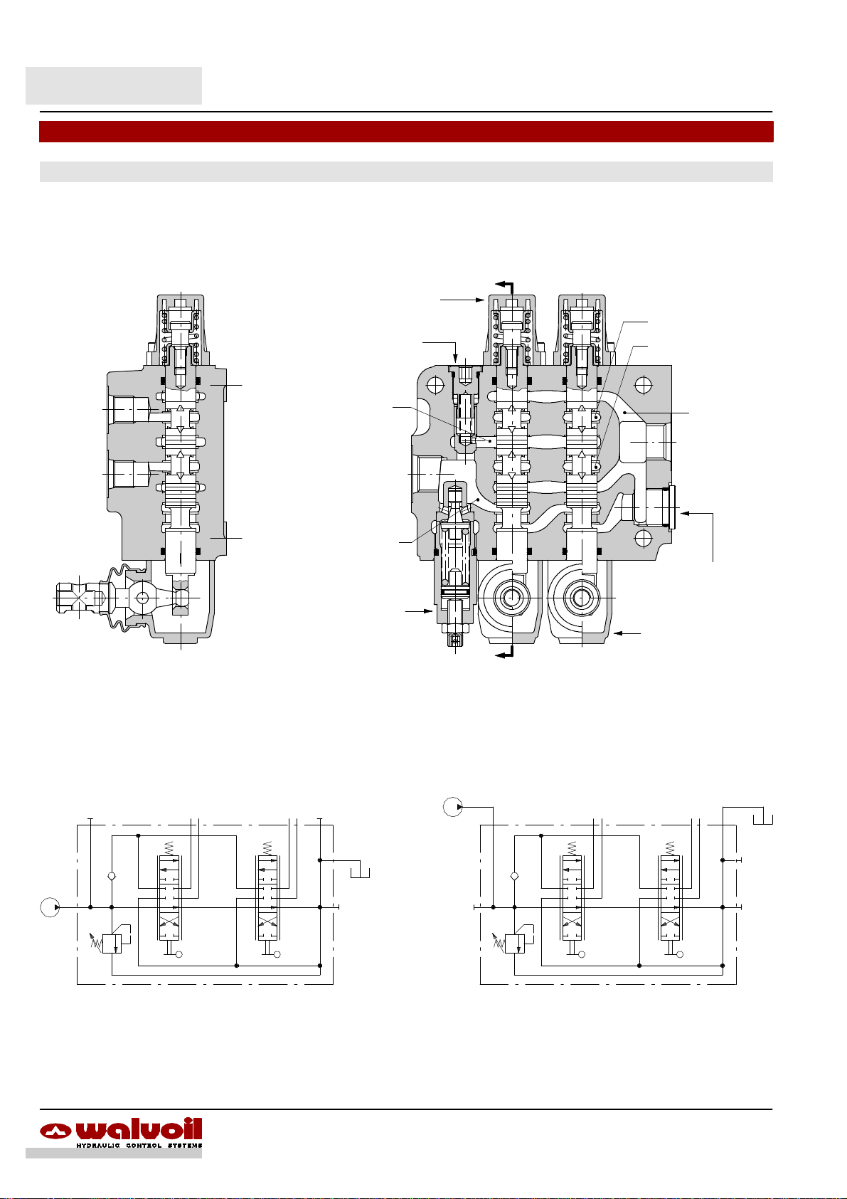
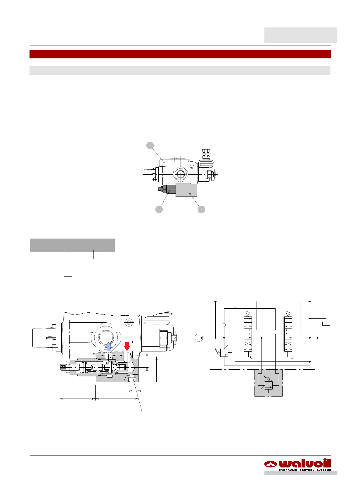
Hydraulic circuit
Parallel
Standard configuration with side inlet and outlet and open center (AET execution).
Positioner kit
Check valve
Allen wrench 4
24 Nm / 17.7 lbft
Port A line
Port B line
A
Pressure line
Tank line
T
B
Flow through
Main relief valve
Standard configuration
P
(LC)
Plug for open center
Allen wrench 8
24 Nm / 17.7 lbft
Lever pivot box
Configuration with upper inlet and outlet
T
A1 B1 A2 B2
A1 B1 A2 B2
P
T
P
120
1750
Ex.: SD5/2--P(JG3--120)/18L/18L/AET
120
1750
Ex.: SD5/2--P(JG3--120)/18L/18L/AET--PSA
6 DAT003A
Page 7
Open center
From side inlet to side outlet.
A1 A2 A3
P
B1 B2 B3
Inlet to work port
A4 A5 A6
A7
B4 B5 B6 B7
SD5
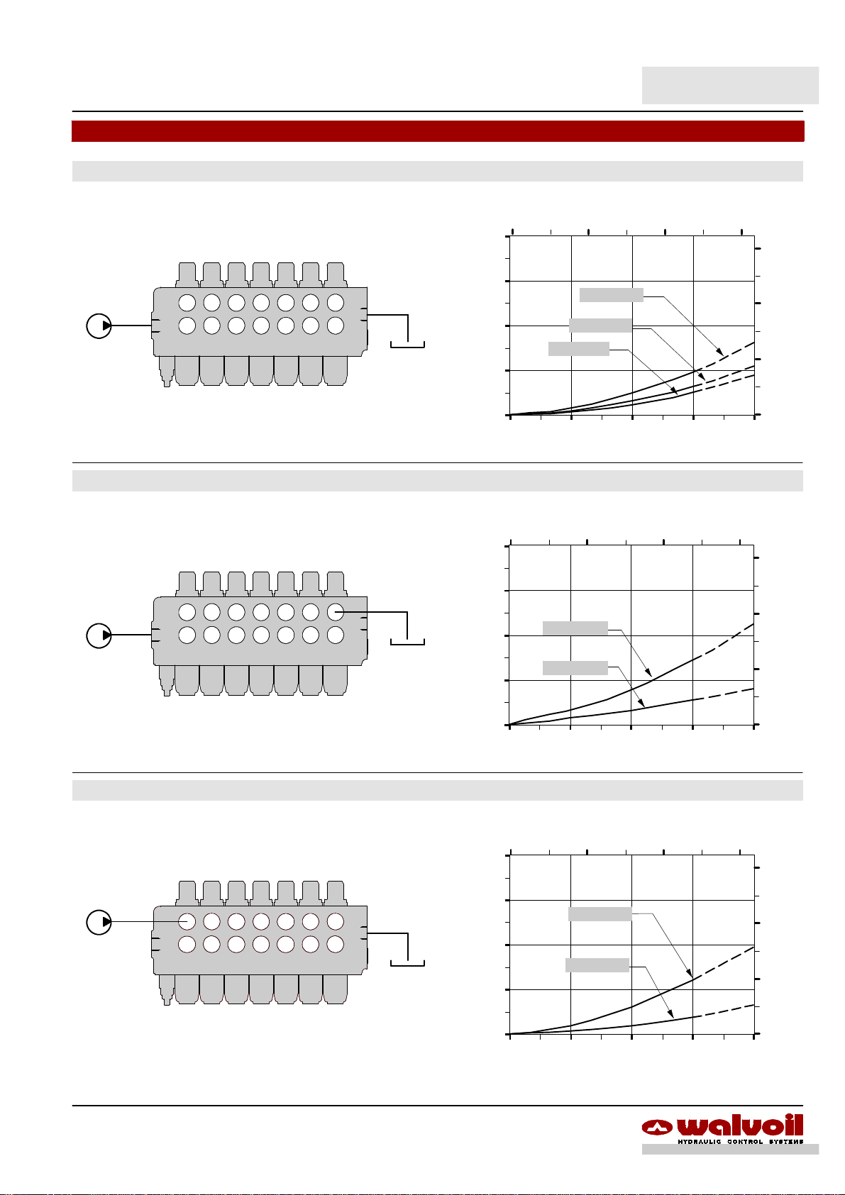
Performance data (pressure drop vs. flow)
5 10 15(US gpm)
40
(bar)
30
T
20
Pressure drop
10
0
0 15 30 45 60
7 sections
4 sections
2 sections
Flow
540
(psi)
360
180
(l/min)
From side inlet to A port (spool in position 1) or B port (spool in position 2).
40
(bar)
A1 A2 A3
P
B1 B2 B3
A4 A5 A6
A7
B4 B5 B6 B7
T
30
20
Pressure drop
10
Work port to outlet
From A port (spool in position 2) or B port (spool in position 1) to side outlet.
(bar)
A1 A2 A3
P
B1 B2 B3
A4 A5 A6
A7
B4 B5 B6 B7
T
Pressure drop
5 10 15
P®A7(B7)
P®A1(B1)
0
0 15 30 45 60
Flow
5 10 15(US gpm)
40
30
A1(B1)®T
20
A7(B7)®T
10
(US gpm)
540
(psi)
360
180
(l/min)
540
(psi)
360
180
NOTE -- Measured with spool type 1.
0
0 15 30 45 60
Flow
(l/min)
7DAT003A
Page 8
SD5
Ordering codes
Description example:
Valve setting (bar)
1stsection following section
Valve setting (bar)
SD5 / 2 -- P (JG3--120) / 1 8 L / 1 8IM . P3(G3--100) / AET -- SAE *
1.
2.
6.
3.
4. 5.
9.
6. 8.
7.
I
7.
8.
3.
4.
1.
II
2.
1. Body kits *
TYPE CODE DESCRIPTION
1--P 5KC1197000 Parallel, 1 section
2--P 5KC1227000 Parallel, 2 sections
3--P 5KC1247000 Parallel, 3 sections
4--P 5KC1277000 Parallel, 4 sections
5--P 5KC1317000 Parallel, 5 sections
6--P 5KC1357000 Parallel, 6 sections
7--P 5KC13E7000 Parallel, 7 sections
Include boby, seals and load check valve.
2. Inlet relief options page 10
TYPE CODE DESCRIPTION
VMD5 direct pressure relief valve type J
(JG2--80) 5KIT105412 Range 40 to 80 bar / 580 to 1150 psi
standard setting 80 bar / 1150 psi
(JG3--120) 5KIT105413 Range 63 to 200 bar / 900 to 2900 psi
standard setting 120 bar / 1750 psi
(JG4--220) 5KIT105414 Range160 to 315bar/ 2300 to4600psi
standard setting 220 bar / 3200 psi
Standard setting is referred to 10 l/min -- 2.64 US gpm flow.
SV XTAP623282 Relief valve blanking plug
5.
3. Spool options page 11
TYPE CODE DESCRIPTION
1 3CU1210130 Double acting, 3 positions, with A and B
closed in neutral position
1A 3CU1221130 Doubleacting, 3 positions, with A open to
tank in neutral position
1B 3CU1222130 Doubleacting, 3 positions, with B open to
tank in neutral position
2 3CU1225130 Double acting, 3 positions, with A and B
open to tank in neutral position
2H 3CU1225225 Double acting, 3 positions, with A e B
partially open to tank in neutral position
3 3CU1231130 Singleacting on A, 3 positions, Bplugged
requires G3/8 plug (see part I )
Special spools for particular positioner kits page 14. . . . . . . . . . . . . . .
5DY 3CU1242220 Double acting, 4 positions, floating circuit
in 4thposition with spool in
5PY 3CU1245620 Double acting, 4 positions, floating circuit
in 4thposition with spool out, fitted with
check valve
8 3CU1262120 Double acting, 4 positions, regenerative
circuit in 4thposition with spool in
Special spools for standard positioner kits page 17. . . . . . . . . . . . . . . .
8F 3CU1261100 Double acting, 3 positions, regenerative
circuit in 2ndposition with spool out
8 DAT003A
Page 9
SD5
Codici di ordinazione
4. “A” side spool positioners page 18
TYPE CODE DESCRIPTION
8 5V08105000 With spring return in neutral position
8D 5V08105200 With spring return in neutral position and
pin with M6 female thread for dual control
8D2 5V08105220 With spring return in neutral position and
pin with M8 male thread for dual control
8F2 5V08105101 With spring return in neutral position and
adjustable flow limiter
19 5V19105000 2 positions, with spring return in neutral
position from position 1
20 5V19105000 2 positions, with spring return in neutral
position from position 2
9 5V09105010 With detent in position 1 and springreturn
in neutral position
10 5V10105010 Withdetent in position 2 and spring return
in neutral position
11 5V11105000 Detent in positions neutral, 1 and 2
12 5V12105000 Detent in positions 1 and 2
15 5V15105000 2 positions, detent in positions 1 and
neutral
16 5V16105000 2 positions, detent in positions 2 and
neutral
9B 5V09202010 Withdetent in position 1 and spring return
in neutral position
10B 5V10202010 With detent in position 2 and spring return
in neutral position
11B 5V11202010 Detent in positions 1 and 2 and spring
return in neutral position
8MS3 5V08105553 With spring return in neutral position,
operation signalling in position 1 and 2,
prearranged for centralized microswitch
control
8MG1 5V08105670 With spring return in neutral position and
microswitch in position 1
8MG2 5V08105680 With spring return in neutral position and
microswitch in position 2
8MG3 5V08105660 With spring return in neutral position and
microswitch in positions 1 and 2
8M3 5V08105400 With spring return in neutral position and
external pin for microswitch control in
positions 1 and 2
8EM2 5V08105580 With spring return in neutral position and
12VDC electromagnetic detent in pos. 2
5V08105590 As previous, 24VDC
8MHE3(NC) 5V08105541 With spring return in neutral position and
spool postioning ON/OFF electric signal
circuit normally closed
8MHE3(NO) 5V08105540 As previous, with circuit normally open
8P 5V08105701 ON/OFF pneumatic kit
8EP3 5V08105735 ON/OFF 12 VDC electro--pneumatic kit
5V08105740 ON/OFF 24 VDC electro--pneumatic kit
8ED3 5V08105350 ON/OFF 12 VDC electro--hydraulic kit
5V08105351 ON/OFF 24 VDC electro--hydraulic kit
Particular positioner kits for special spools page 14. . . . . . . . . . . . . . .
13NZ 5V13305010....4 positions with spring return in neutral
pos.and detentin 4thpos.:for spool5DY
13QN 5V13405020 4 positions with spring return in neutral
pos. and detent in 4thpos.:for spool5PY
13FZ 5V13505400 4 positions with spring return in neutral
position: for spool 8
5. “B” side options page 30
TYPE CODE DESCRIPTION
L 5LEV105000 Standard lever box
LM10 5LEV205000 Lever box for M10 handlever
LF1 5LEV105102 Lever box with adjustable flow limiter
LEB 5LEV605000 Safety lever box, vertical configuration
LUP 5LEV805005 Safety lever box, horizontal configuration
SLP 5COP105000 Witout lever box, with dust--proof plate
SLC 5COP205000 Witout lever box, with endcap
TQ 5TEL105110 Flexible cable connection
LCB 5CLO205100 Joystick lever for 2 sections operation
6. Complete spool control kits page 34
Hydraulic proportional and ON/OFF electric spool controlkits.
7. Service valves page 42
Portrelief,anti--shock,pilot operatedcheckandflow regulation
valves.
8. Outlet port options pag. 40
TYPE CODE DESCRIPTION
AET XTAP623170 Open center plug
AEK 3XTAP522282 Closed center plug
AE 3XGIU527470* SAE8 power beyond sleeve
AET--L 5CAR405700* With hydraulic pilot unloader valve
AET--EL YCAR405305 With 12VDC electric control unloader
valve
YCAR405310 With 24VDC electric control unloader
valve
AET--LT XTAP523370 Prearranged for unloader valve, with
blanking plug
9. Inlet and outlet selection * page 6
TYPE CODE DESCRIPTION
PSL 3XTAP822150 Sideports; need n.2 SAE8 plugs, standard
configuration (omit in valve description)
PSA 3XTAP822150 Upper ports; need n.2 SAE8 plugs
I ”A” and “B” ports plugs *
TYPE CODE DESCRIPTION
SAE6 3XTAP817130 For single acting spool type 3
II Optional handlevers
TYPE CODE DESCRIPTION
AL01/M8x120 170011012 For lever L: height 120 mm / 4.72 in
AL01/M10x150 170012015 For lever LM10:
height 150 mm / 5.91 in
AL08/M12x150 170013115 For joystick LCB:
height 150 mm / 5.91 in
NOTE (*) -- Codes are referred to UN-UNF threads.
9DAT003A
Page 10
SD5
Inlet relief options
Direct pressure relief vave
VMD5 ( J G 3 -- 120 )
Standard setting in bar (for value see page 8)
Adjustable spring type (2, 3, 4).
Adjustment type (G, H)
Adjustment type
G: with screw H: valve set and locked
Wrench 19
42 Nm / 31 lbft
Wrench 13
24 Nm / 17.7 lbft
Allen wrench 4
Cap code: 3COP117260
Performance data
5 10 15
400
(bar)
300
200
Pressure
100
0
0 20 40 60
Flow
(US gpm)
(psi)
4500
3000
1500
(l/min)
SV : relief valve blanking plug
Allen wrench 10
42 Nm / 31 lbft
2.03 2.34
59.5max. 51.5
Spring nr. 4 (red band)Spring nr. 3 (blue band)Spring nr. 2 (green band)
5 10 15
400
(bar)
300
200
Pressure
100
0
0 20 40 60
Flow
(l/min)
(US gpm)
(psi)
4500
3000
1500
400
(bar)
300
200
Pressure
100
0
0 20 40 60
5 10 15
Flow
Response time
(% DP)
105%
95%
90%
(US gpm)
(psi)
4500
3000
1500
(l/min)
Pressure
10%
0,02”
RESPONSE TIME
100 bar
1450 psi
Time (”)
10 DAT003A
Page 11
SD5
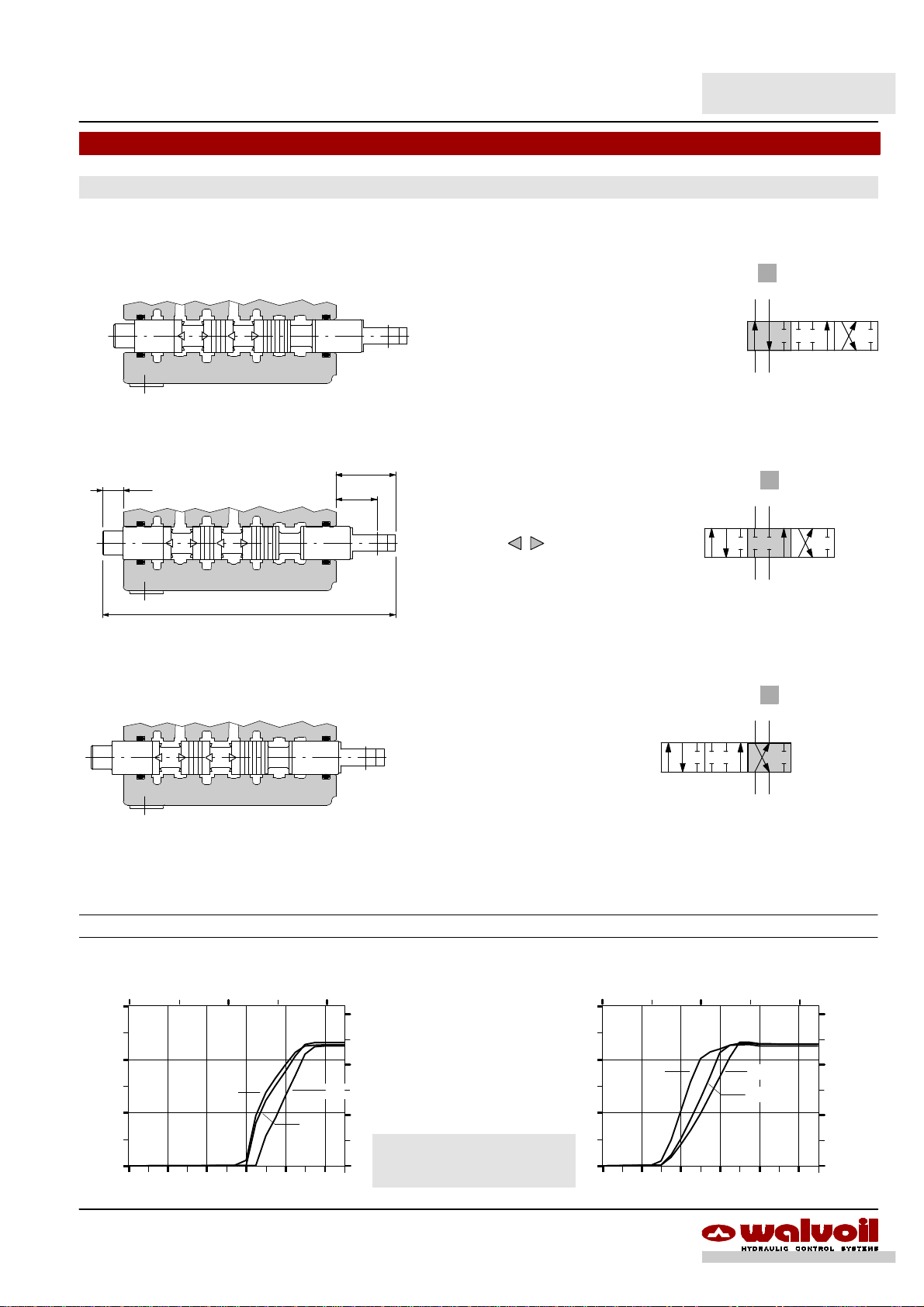
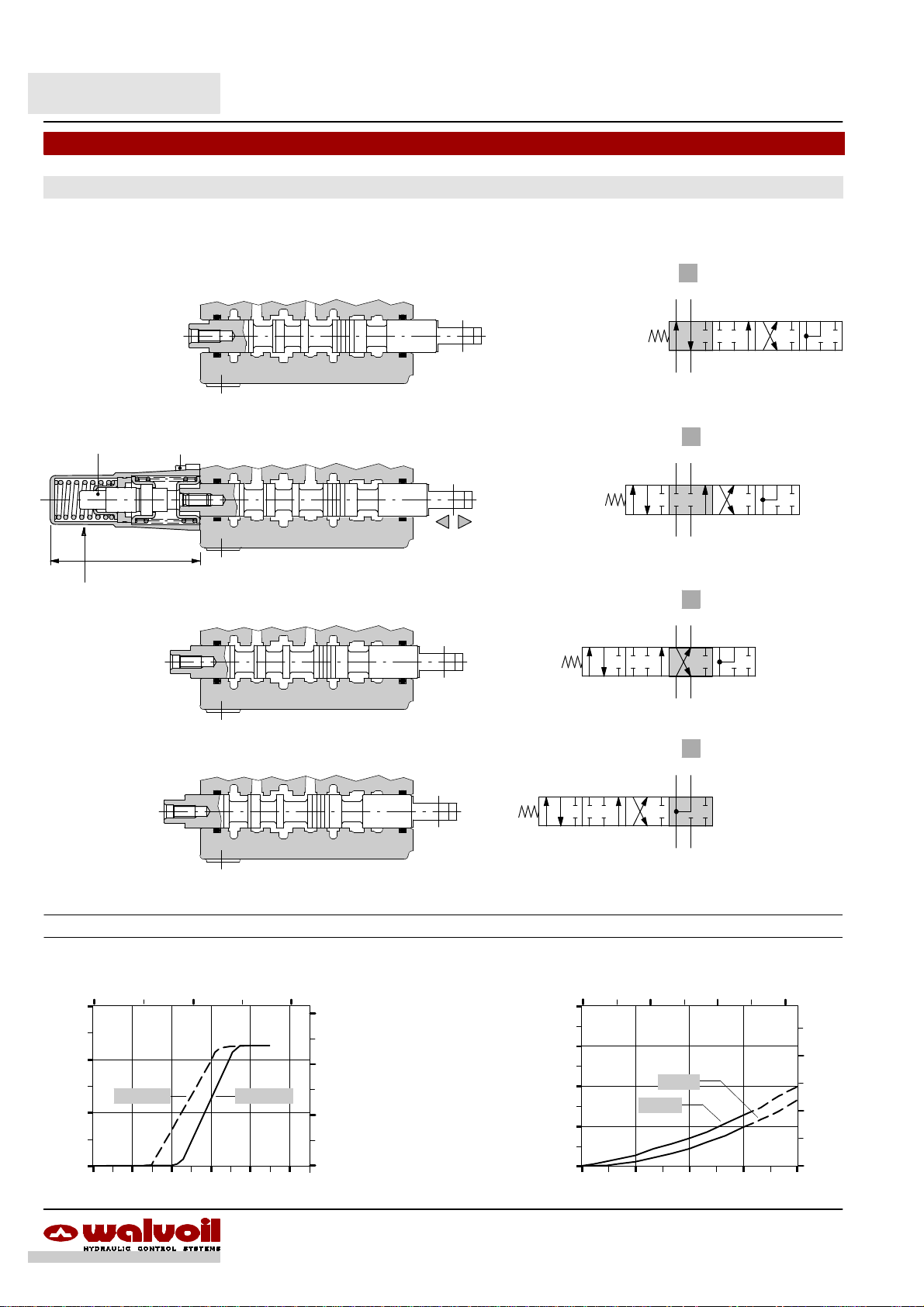
Spool options
Type 1
For special requirement, spool 1CS code 3CU1210200 suggested for flow from 15 to 30 l/min -- 4 to 7.9 US gpm and spool 1CEX
code 3CU1210230 suggested for flow up to 15 l/min -- 4 US gpm, are available.
A B
T P LCT
P ® A B ® T
29
10
0.39
A B
0.35
20
0.79
T P LCT
142
5.59
P--A--B--T closed, with flow through line (LC) open
A B
"
stroke
201
A B
+ 5.5 mm
+ 0.22 in
P T
201
A B
P T
201
A B
T P LCT
P® B A ® T
Performance data
60
(l/min )
40
Flow
20
0
0.0 1.0 2.0 3.0 4.0 5.0
0.1 0.2
F
Stroke
stroke
-- 5.5 mm
-- 0.22 in
A
Spool metering A(B)®TSpool metering P®A(B)
(in)
15
(US gpm)
10
J
5
Y
5.5 5.5
(mm)
Qin = 45 l/min -- 12 US gpm
F
Y
J
P
(on ports)
P
(on ports)
P
(on ports)
= 63bar / 900 psi
= 100bar / 1450 psi
= 250bar / 3600 psi
60
(l/min )
40
Flow
20
0
0.0 1.0 2.0 3.0 4.0 5.0
0.1 0.2
J
Stroke (mm)
P T
F
Y
(in)
15
(US gpm)
10
5
11DAT003A
Page 12
SD5
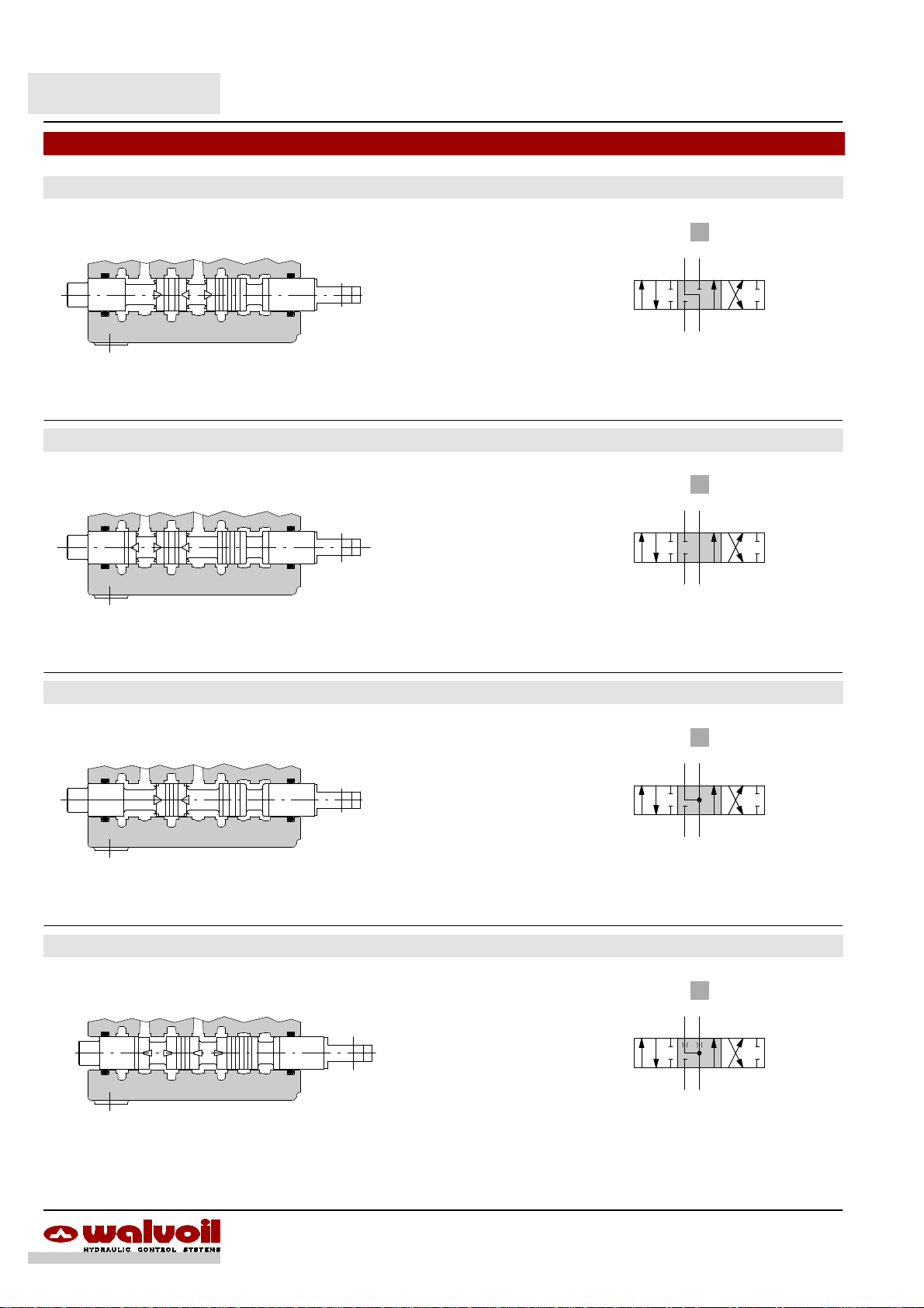
Spool options
Type 1A
A B
T P LCT
P--B closed, A®T, flow through line (LC) open
Type 1B
A B
T P LCT
P--A closed, B®T, flow through line (LC) open
201
A B
P T
201
A B
P T
Type 2
A B
T P LCT
P closed, A --B®T, flow through line (LC) open
Type 2H
A B
T P LCT
P closed, A --B partially open to tank,
flow through line (LC) open
201
A B
P T
201
A B
P T
12 DAT003A
Page 13
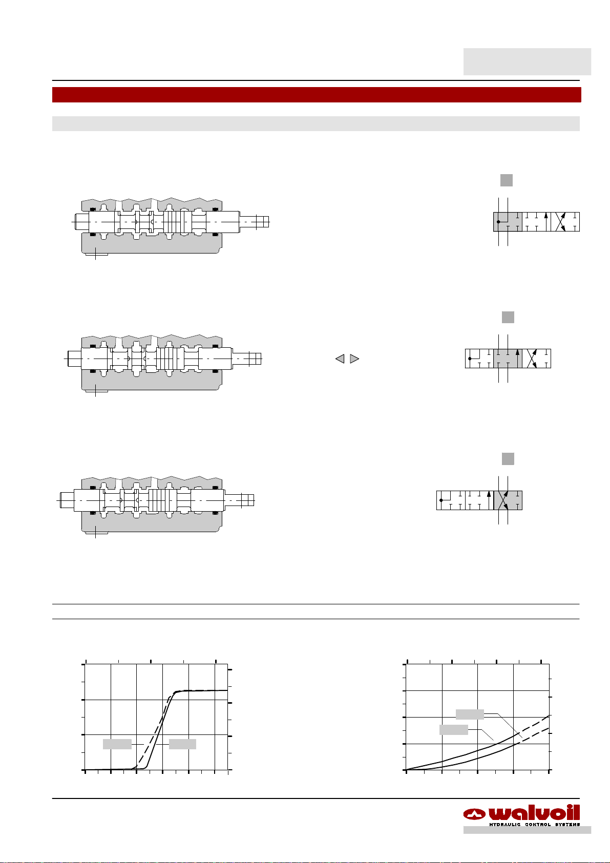
Type 3
SD5
Spool options
A
201
A
+ 5.5 mm
stroke
"
+ 0.22 in
T P LCT
P ® A
Port B plugged
A
Allen wrench 6 -- 24 Nm / 17.7 lbft
T P LCT
P--A--T closed, flow through line (LC) open
A
T P LCT
A
stroke
P T
201
A
P T
201
A
-- 5.5 mm
-- 0.22 in
P T
A ® T
Performance data
0.1 0.2
60
(l/min )
40
Flow
20
F
0
0.0 1.0 2.0 3.0 4.0 5.0
Stroke
J
Y
(mm)
(in)
15
(US gpm)
10
5
5.5
Qin = 45 l/min -- 12 US gpm
F
P
Y
P
P
J
(on ports)
(on ports)
(on ports)
= 63bar / 900 psi
= 100bar / 1450 psi
= 250bar / 3600 psi
13DAT003A
Spool metering A®TSpool metering P®A
0.1 0.2
60
(l/min)
40
J
Flow
20
0
0.0 1.0 2.0 3.0 4.0 5.0
Stroke (mm)
(in)
15
(US gpm)
F
Y
10
5
5.5
Page 14

SD5
Spool options
Type 5DY
It needsspecial body with extramachining: for information pleasecontact Customer Service. Thisspool must becoupled withpositioner type 13NZ.
Also available spool with check valve on A port; type 5WY code 3CU1242320.
201
3
3
Allen wrench 4
6.6 Nm / 4.9 lbft
Wrench 6
9,8 Nm / 7.2 lbft
A B
T P LCT
P® A , B ® T
A B
"
stroke
+ 4.5 mm
+ 0.18 in
A B
P T
201
A B
72.5
2.85
Positioner kit 13NZ
Locking force:
280 N / 63 lbf ±10%
Unlocking force:
300 N / 67.4 lbf ±10%
Performance data
Spool metering
Qin = 45 l/min -- 12 US gpm / P
0.1 0.2
60
(l/min )
40
P®A A®T
Flow
20
T P LCT
P--A--B--T closed
flow through line (LC) open
A B
T P LCT
P® B , A ® T
A B
T P LCT
A--B ® T (float in lock position)
(on ports)
= 100 bar -- 1450 psi
(in)
15
(US gpm)
10
5
A
stroke
AA
stroke
-- 4.5 mm
-- 0.18 in
-- 9 mm
-- 0.35 in
(bar)
Pressure
P T
201
A B
P T
201 3
A B
P T
Pressure drop in position 3
20
15
10
5
(last section)
5 10 15
A®T
B®T
3
(US gpm)
(psi)
200
100
0
0.0 1.0 2.0 3.0 4.0 5.0
Stroke (mm)
5.5
0
0 15 30 45 60
Flow (l/min)
14 DAT003A
Page 15
SD5
Spool options
Type 5PY
It needsspecial body with extramachining: for information pleasecontact Customer Service. Thisspool must becoupled withpositioner type 13QN.
Locking force:
370 N / 83.2 lbf ±10%
Unlocking force:
390 N / 87.7 lbf ±10%
Allen wrench 4
6.6 Nm / 4.9 lbft
Wrench 6
9,8 Nm / 7.2 lbft
72,5
Positioner kit 13QN
Wrench 12
9,8 Nm / 7.2 lbft
A B
T P LCT
A--B ® T (float in lock position)
A B
T P LCT
P® A , B ® T
A B
T P LCT
P--A--B--T closed
flow through line (LC) open
A B
""
stroke
"
stroke
+ 9 mm
+ 0.35 in
+ 4.5 mm
+ 0.18 in
013 2
A B
P T
013 2
A B
P T
013 2
A B
P T
013 2
A B
Performance data
Spool metering
Qin = 45 l/min -- 12 US gpm / P
0.1 0.2
60
(l/min)
40
Flow
20
0
0.0 1.0 2.0 3.0 4.0 5.0
Stroke (mm)
T P LCT
P® B , A ® T
(on ports)
= 100 bar -- 1450 psi
P®BB®T
(in)
15
(US gpm)
10
5
5.5
A
stroke
15DAT003A
-- 4.5 mm
-- 0.18 in
P T
Pressure drop in position 3
(last section)
5 10 15
20
(bar)
15
10
Pressione
5
0
0 15 30 45 60
A(B)®T
Portata (l/min)
(US gpm)
(psi)
200
100
Page 16
SD5
Spool options
Type 8
It needsspecial body with extramachining: for information pleasecontact Customer Service. Thisspool must becoupled withpositioner type 13FZ.
201
3
Allen wrench 5
9.8 Nm / 7.2 lbft
Allen wrench 4
6.6 Nm / 4.9 lbft
A B
T P LCT
P® A , B ® T
A B
"
stroke
+ 4.5 mm
+ 0.18 in
A B
P T
201 3
A B
72.5
2.85
Positioner kit 13FZ
Performance data
Spool metering
Qin = 45 l/min -- 12 US gpm / P
0.1 0.2
60
(l/min )
40
Flow
20
T P LCT
P--A--B--T closed
flow through line (LC) open
A B
T P LCT
P® B , A ® T
A B
T P LCT
P ® A--B (regenerative)
= 100 bar -- 1450 psi
(on ports)
(in)
15
(US gpm)
10
P®A(B)A(B)®T
5
A
stroke
AA
stroke
-- 4.5 mm
-- 0.18 in
-- 7.5 mm
-- 0.29 in
(bar)
Pressure
P T
201
A B
P T
201 3
A B
P T
Pressure drop in positione 3
20
15
10
5
(last section)
5 10 15
A®B
P®B
3
(US gpm)
(psi)
200
100
0
0.0 1.0 2.0 3.0 4.0 5.0
Stroke
(mm)
(mm)
5.5
0
0 15 30 45 60
Flow (l/min)
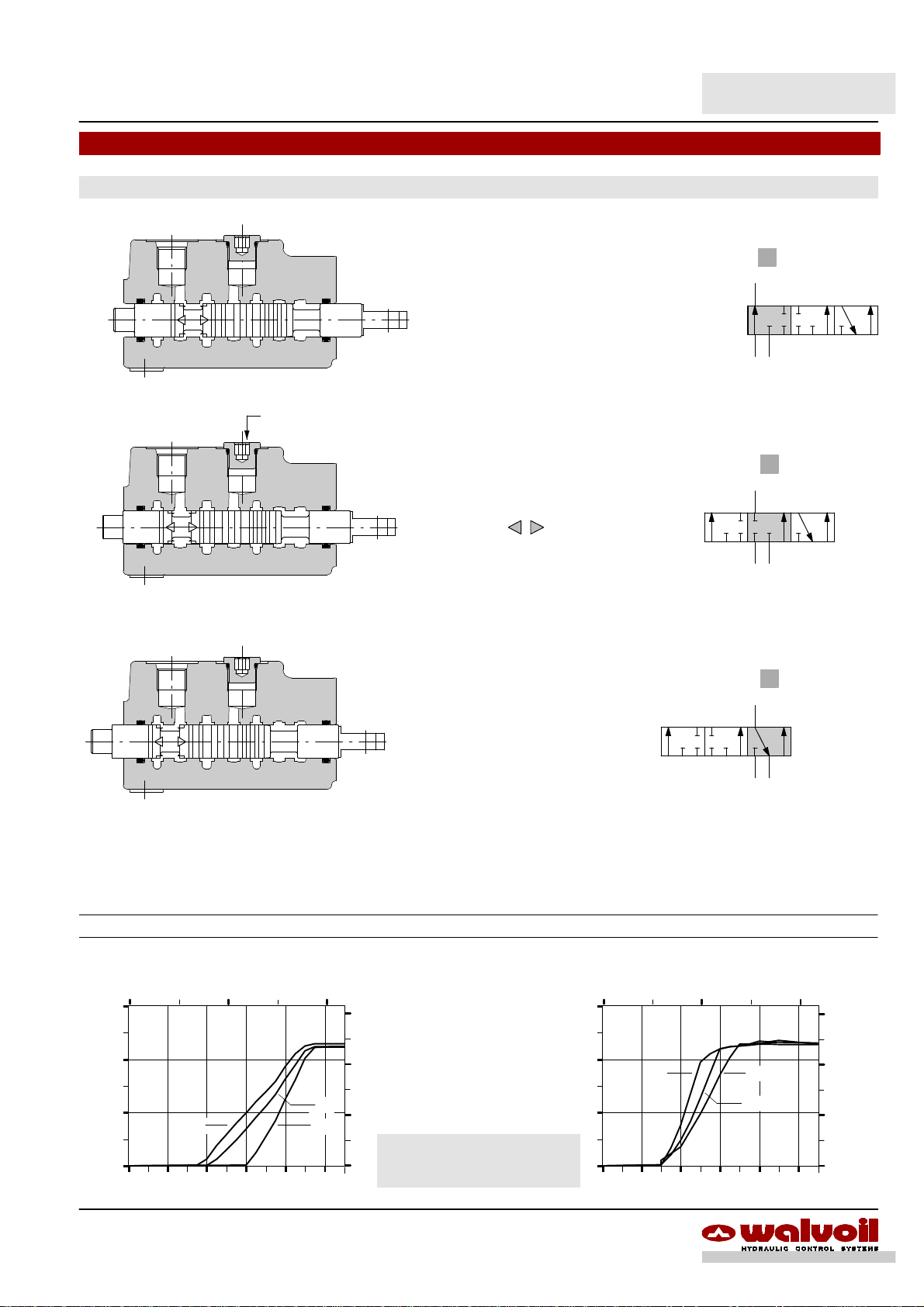
16 DAT003A
Page 17
Type 8F
It needs special body with extra machining: for information please contact Customer Service.
SD5
Spool options
A B
T P LCT
P ® A--B (regenerative)
A B
T P LCT
P--A--B--T closed, flow through line (LC) open
A B
"
stroke
201
A B
+ 5.5 mm
+ 0.22 in
P T
201
A B
P T
201
A B
T P LCT
P® B , A ® T
Performance data
Spool metering
Qin = 45 l/min -- 12 US gpm / P
0.1 0.2
60
(l/min)
40
Flow
20
0
0.0 1.0 2.0 3.0 4.0 5.0
Stroke (mm)
(on ports)
P®BA®T
= 100 bar -- 1450 psi
(in)
15
(US gpm)
10
5
5.5
A
stroke
-- 5.5 mm
-- 0.22 in
P T
Pressure drop in position 1
(last section)
5 10 15
20
(bar)
15
10
Pressure
5
0
0 15 30 45 60
B®A
P®A
Flow (l/min)
(US gpm)
(psi)
200
100
17DAT003A
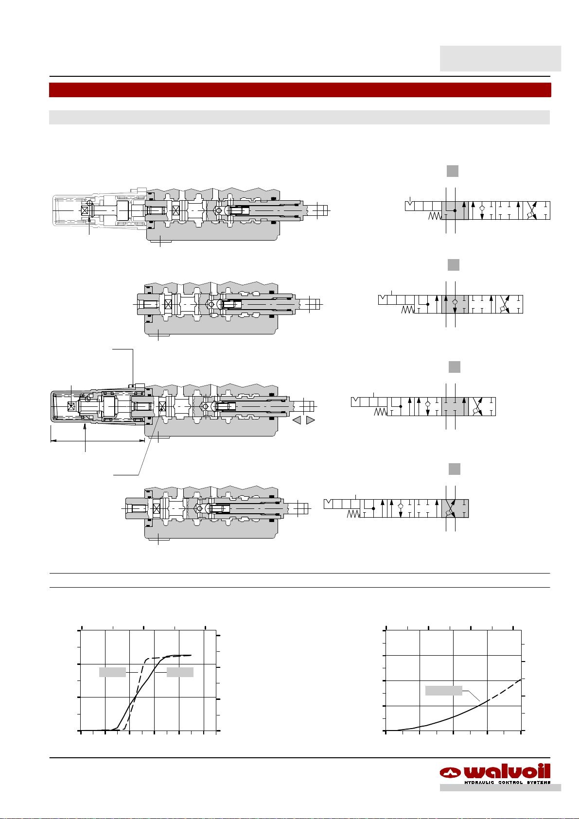
Page 18

SD5
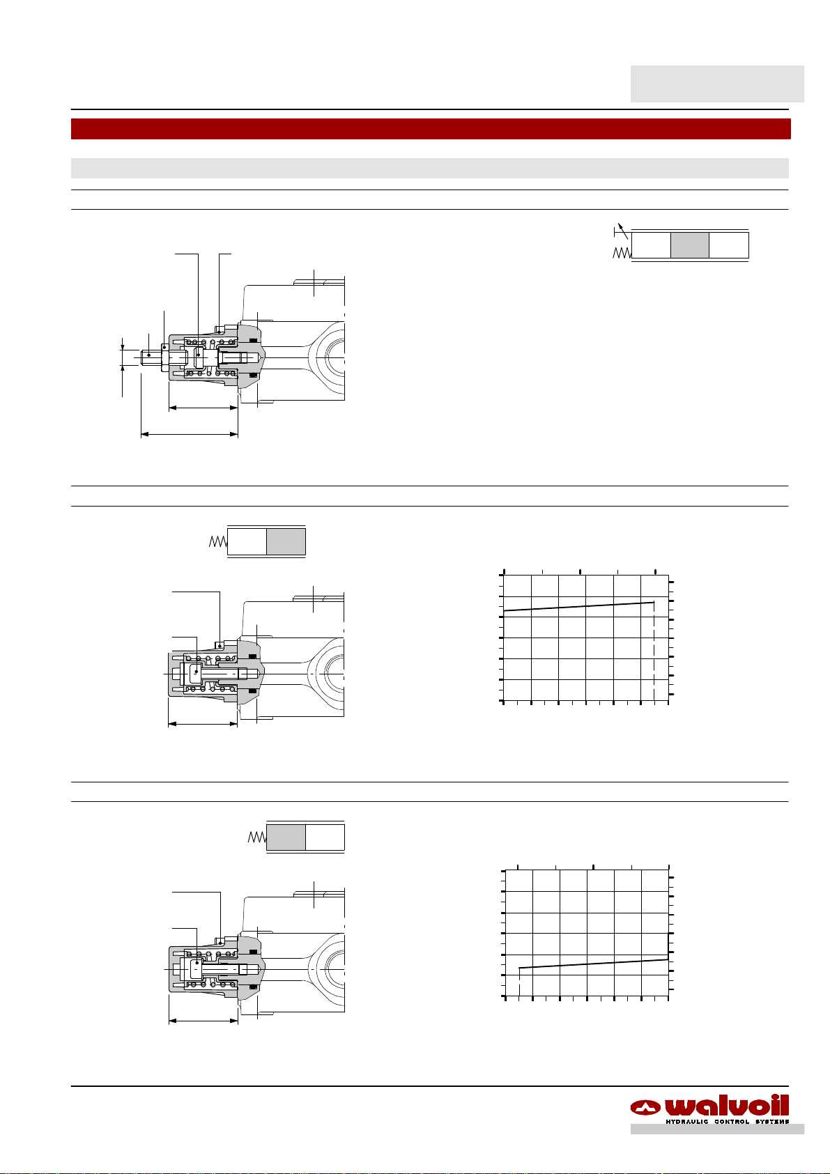
”A” side spool positioners
With spring return in neutral position
8 kit
It’ssuppliedwithstandard springtypeD(see force--strokediagram)andavailablewithlighterspringtype C(8MCcode:5V08205000)
or heavier type E (8ME code: 5V08405000).
Force--stroke diagram
(in)
E
D
C
(mm)
(lbf)
60
40
20
--20
--40
--60
Allen wrench 4
6.6 Nm / 4.9 lbft
Allen rench 5
9.8 Nm / 7.2 lbft
36.5
1.44
201
300
(N)
200
100
0
Force
C
--100
D
--200
E
--300
--6 --5 --4 --3 --2 --1 0 1 2 3 4 5 6
--0.1--0.2 0
Stroke
0.1 0.2
0
8D kit
8D2 kit
Allen wrench 4
6.6 Nm / 4.9 lbft
Wrench 9
9.8 Nm / 7.2 lbft
12
0.47
M6
Allen wrench 4
6.6 Nm / 4.9 lbft
Wrench 9
9.8 Nm / 7.2 lbft
201
36.5
1.44
44
1.73
201
M8
40
1.57 1.44
84
3.31
36.5
18 DAT003A
Page 19
With spring return in neutral position
8F2 kit
SD5
“A” side spool positioners
Allen wrench 5
9.8 Nm / 7.2 lbft
Wrench 13
24 Nm / 17.7 lbft
Allen wrench 4
M8x1
19 kit
Allen wrench 4
6.6 Nm / 4.9 lbft
Allen wrench 5
9.8 Nm / 7.2 lbft
51.5
2.03
36.5
1.44
36.5
1.44
Allen wrench 4
6.6 Nm / 4.9 lbft
01
Force--stroke diagram
300
(N)
200
100
0
Force
--100
--200
--300
0 1 2 3 4 5 6
0.1 0.2
Stroke
(in)
(mm)
201
(lbf)
60
40
20
0
--20
--40
--60
20 kit
Allen wrench 4
6.6 Nm / 4.9 lbft
Allen wrench 5
9.8 Nm / 7.2 lbft
36.5
1.44
20
(N)
Force
--100
--200
--300
Force--stroke diagram
--0.1--0.2
300
200
100
0
--6 --5 --4 --3 --2 --1 0
Stroke
(in)
(mm)
(lbf)
60
40
20
0
--20
--40
--60
19DAT003A
Page 20
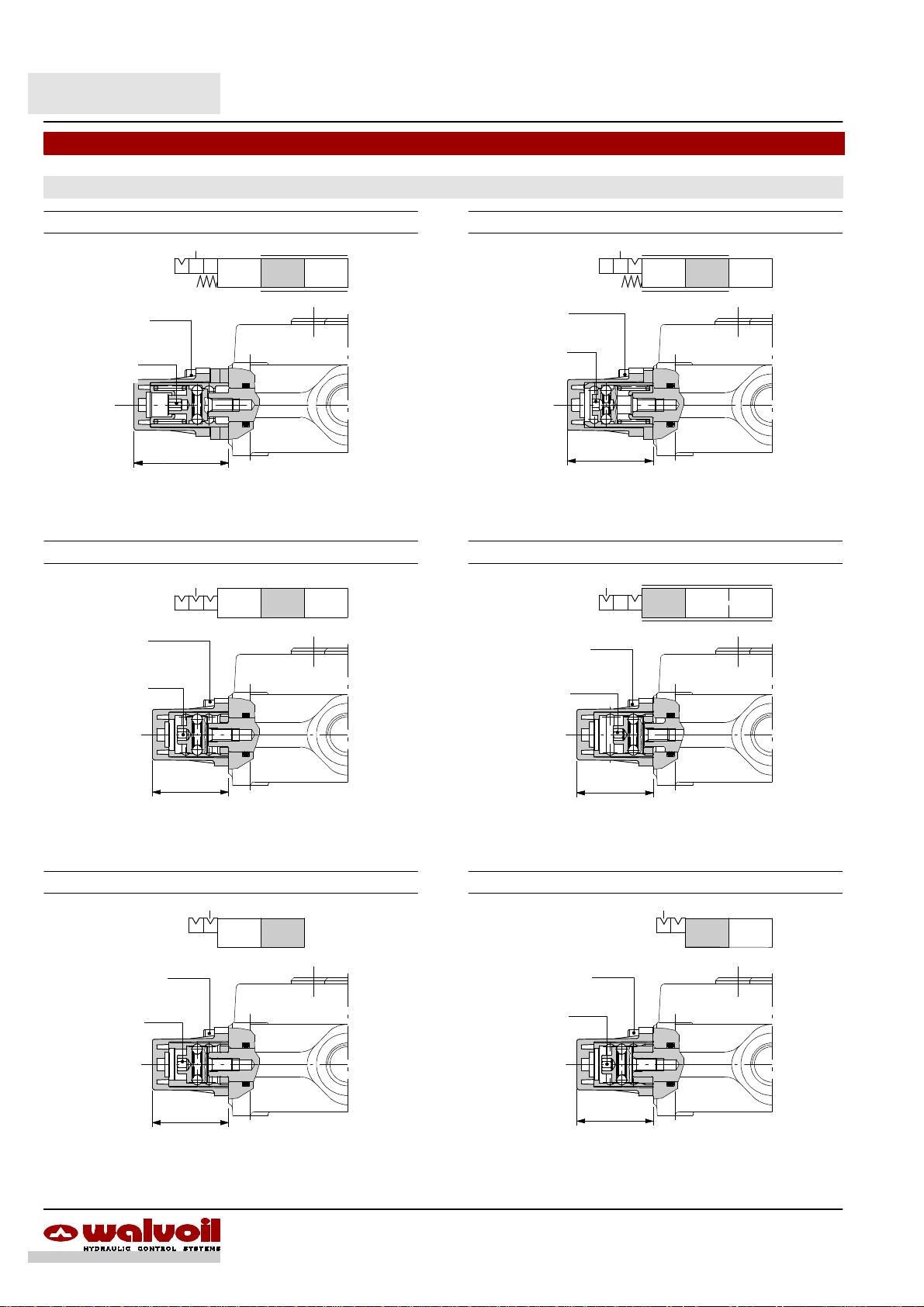
SD5
”A” side spool positioners
With detent
9 kit
Allen wrench 4
6.6 Nm / 4.9 lbft
Allen wrench 5
9.8 Nm / 7.2 lbft
45,545.5
1.79
Operating features
Locking force (from pos. 0 to 1) :150 N /33.7 lbf ±10%. . .
Unlocking force (from pos. 1 to 0) : 140 N /31.5 lbf ±10%.
11 kit
Allen wrench 4
6.6 Nm / 4.9 lbft
Allen wrench 5
9.8 Nm / 7.2 lbft
10 kit
201201
Allen wrench 4
6.6 Nm / 4.9 lbft
Allen wrench 5
9.8 Nm / 7.2 lbft
41
1.61
Operating features
Locking force (from pos. 0 to 2) :150 N /33.7 lbf ±10%. . .
Unlocking force (from pos. 2 to 0) : 140 N /31.5 lbf ±10%.
12 kit
201
Allen wrench 4
6.6 Nm / 4.9 lbft
Allen wrench 5
9.8 Nm / 7.2 lbft
201
36.5
1.44
Operating features
Locking and unlocking force : 120 N / 27 lbf ±10%. . . . . .
15 kit
Allen wrench 4
6.6 Nm / 4.9 lbft
Allen wrench 5
9.8 Nm / 7.2 lbft
36.5
1.44
Operating features
Locking and unlocking force : 100 N /22.5 lbf ±10%. . . . . .
36.5
36,5
1.44
Operating features
Locking and unlocking force : 100 N /22.5 lbf ±10%. . . . . .
16 kit
01
Allen wrench 4
6.6 Nm / 4.9 lbft
Allen wrench 5
9.8 Nm / 7.2 lbft
36.5
1.44
Operating features
Locking and unlocking force : 100 N /22.5 lbf ±10%. . . . . .
20
20 DAT003A
Page 21

“A” side spool positioners
With detent and sprimg return to neutral position from either directions
9B kit
SD5
Allen wrench 4
6.6 Nm / 4.9 lbft
10B kit
Allen wrench 4
6.6 Nm / 4.9 lbft
72.5
2.85
Allen wrench 5
9.8 Nm / 7.2 lbft
72.5
2.85
Allen wrench 5
9.8 Nm / 7.2 lbft
201
300
(N)
200
Force
--100
--200
--300
100
0
Fromposition2 to 0
From position 0to 2
--6 --5 --4 --3 --2 --1 0 1 2 3 4 5 6
Locking--unlocking area
Ulocking force: 200 N / 45 lbf ±10%:
201
300
(N)
200
100
Force
--100
--200
--300
:
0
--6 --5 --4 --3 --2 --1 0 1 2 3 4 5 6
Locking--unlocking area
Ulocking force: 200 N / 45 lbf ±10%:
Force--stroke diagram
--0.1--0.2 0
Stroke
Force--stroke diagram
--0.1--0.2 0
Fromposition2 to 0
From position 0to 2
Stroke
0.1 0.2
Fromposition0 to 1
From position 1to 0
0.1 0.2
Fromposition0 to 1
From position 1to 0
(in)
(lbf)
60
40
20
0
--20
(mm)
(in)
(mm)
--40
--60
(lbf)
60
40
20
0
--20
--40
--60
:
11B kit
Allen wrench 4
6.6 Nm / 4.9 lbft
72.5
2.85
Allen wrench 5
9.8 Nm / 7.2 lbft
201
300
(N)
200
100
Force
--100
--200
--300
:
0
--6 --5 --4 --3 --2 --1 0 1 2 3 4 5 6
Locking--unlocking area
Ulocking force: 200 N / 45 lbf ±10%:
Force--stroke diagram
--0.1--0.2 0
Fromposition2 to 0
From position 0to 2
Stroke
0.1 0.2
Fromposition0 to 1
From position 1to 0
(in)
(lbf)
60
40
20
0
--20
:
--40
--60
(mm)
21DAT003A
Page 22

SD5
”A” side spool positioners
8MS3 kit: with centralized control for microswitch
Example of a two section valve assembly
Microswitch on
request (see page 25)
58
Rocker arm to
actuate microswitch
2.28
M3
n.2 threads
25.4
1
0.04
1
Bracket for 5MIC100
microswitch
8
0.32
Allen wrench 2.5
6.6 Nm / 4.9 lbft
Allen wrench 2.5
6.6 Nm / 4.9 lbft
A1 B1 A2 B2
P
120
1750
Es.: SD5/2--P(JG3--120)/18MS3L/18MS3L/AET -- KM 2 S 51
Assembling kit
Nr. of working sections
22 DAT003A
T
51 = with bracket for M51 (IP51) microswitch fixing
67 = with bracket for M67 (IP67) microswitch fixing
S = bracket placed on left
D = bracket placed on right
Page 23

8MS3 kit: with centralized control for microswitch
201
Allen wrench 2.5
6.6 Nm / 4.9 lbft
Allen wrench 4
6.6 Nm / 4.9 lbft
58.3
2.29
Notch 1.5 mm / 0.06 in
9.8 Nm / 7.2 lbft
SD5
“A” side spool positioners
Other configurations
8MS1 kit
microswitch operation in
position 1
201
8MS2 kit
microswitch operation in
position 2
201
Microswitches for 8MS kits
Complete with rubber cover and mounting screws.
M51 code: 5MIC100 M67 code: 5MIC200
Dedicated bracket is needed for the assembly
code: 3FLA225052
55.5M42.19
18 4
0.7140.16
Operating features
Max. current / voltage : 5 A / 250 VAC. . . . . . . . . . . . .
Weather protection : IP67. . . . . . . . . . . . . . .
64
2.52
0.83
M3
21 4
0.16
Operating features
Max. current / voltage : 15 A / 480 VAC. . . . . . . . . . . . .
Weather protection : IP51. . . . . . . . . . . . . . .
6
Æ
0.24
25.5 14
1.00
30.2
1.19
Stroke
2.5
0.10
68
2.68
: 0.25 A / 250 VDC
0.55
58.2
7
0.28
Æ
27.1
1.07
1.5
0.06
2.29
33 6
1.30
Stroke
: 0.25 A / 230VDC
0.24
23DAT003A
Page 24

SD5
“A” side spool positioners
With microswitch and spring return in neutral position
8MG3 kit
Microswitch kit with
PACKARD male connector
Wrench 22
42 Nm / 31 lbft
Wrench 10
9.8 Nm / 7.2 lbft
Allen wrench 4
6.6 Nm / 4.9 lbft
103
4.06
8MG3 kit
microswitch operation in
positions 1 and 2
201
Other configuration
8MG1 kit
microswitch operation in
position 1
66,5
Allen wrench 5
9.8 Nm / 7.2 lbft
Allen wrench 4
6.6 Nm / 4.9 lbft
Microswitch operating features
Mechanical life : 5x10⁵operations. . . . . . . . . . .
Electrical life (resistive load) : 105operations -- 7A / 13,5VDC
: 5x10⁴operations -- 10A / 12VDC
Microswitches ordering codes
Thekit consisting ofmicroswitchandconnector,canbeorderedseparately (normally closed NC version is available on request).
CODE DESCRIPTION
4MIC730 Normally open (NO) microswitch kit with PACKARD
male connector: needs C07 female connector
4MIC740 Normally closed (NC) microswitch kit with PACKARD
female connector: nedds C17 male connector
For connection see page NO TAG.
201
8MG2 kit
microswitch operation in
position 2
201
24 DAT003A
Page 25

With microswitch and spring return in neutral position
8M3 kit
SD5
“A” side spool positioners
Allen wrench 4
6.6 Nm / 4.9 lbft
notch 1.5 mm / 0.06 in
9.8 Nm / 7.2 lbft
Allen wrench 2.5
6.6 Nm / 4.9 lbft
36.5
1.44
74
2.91
8EM2: with electromagnetic detent
With spring return in neutral position and electromagnetic detent in position2.
Solenoid kit with DEUTSCH male connector
(need connector type C..., see page
NO TAG)
201
201
Allen wrench 4
6.6 Nm / 4.9 lbft
Notch 1.2 mm / 0.047 in
6.6 Nm / 4.9 lbft
600
23.6
88
3.46
111
4.37
Wrench 10 -- 9.8 Nm / 7.2 lbft
Operating features
Nominal voltage : 12/ 24VDC ± 10%. .. . . .. . . .. . . ..
Power rating : 4 W.. . . . . . . . . . . . . . . . .
Resistance (20 °C) : 36 / 144 Ohm. . . . . . . . . . . . .
Min. release force : 145 N. . . . . . . . . . . . . .
Duty cycle : 100%. . . . . . . . . . . . . . . . . . . .
Solenoid ordering codes
With male DEUTSCH connector
CODE DESCRIPTION
YSOL528465 12 VDC solenoid
YSOL528466 24 VDC solenoid
25DAT003A
Page 26

SD5
“A” side spool positioners
8MHE3 kit: with spring return in neutral position and spool positioning ON/OFF signal
This module supplies two different ON/OFF signals, related to the direction of the spool.
It has two separate contacts which can be normallyopen or normally closed.
Connection DIN43650/C
(needs connector type C11, see page 62)
Notch -- 6.6 Nm / 4.9 lbft
Wrench 5
6.6 Nm / 4.9 lbft
Wrench 10
9.8 Nm / 7.2 lbft
Connector wiring
Position 1 signal
38.5
1.52
Wrench 5
9.8 Nm / 7.2 lbft
44.5
1.75
81
3.19
Vedi particolare A
Position 2 signal
32
4 1
8MHE3(NC) kit 8MHE3(NO) kit
1 2 34
Configuration with
normally closed circuit
View A View A
Configuration with
normally open circuit
Operating features
Power supply range : from 3 da 28 VDC
Max. output current : 500 mA.
Weather protection : IP65.
1 2 34
201201
Ouput signal with NC circuit
Tolerance range
(VDC)
100%
--0.2
12
Voltage
0
--6 --5 --4 --3 --2 --1 0 1 2 3 4 5 6
--0.1
Stroke
0.1
Mobile contact
Fixed contact
0.2 (in)0
(mm)
Mobile contact
Fixed contact
Ouput signal with NO circuit
Tolerance range
(VDC)
100%
--0.2
12
Voltage
0
--6 --5 --4 --3 --2 --1 0 1 2 3 4 5 6
--0.1
Stroke
0.1
0.20
(mm)
26 DAT003A
Page 27

8P: ON/OFF pneumatic kit
SD5
“A” side spool positioners
201
Wrench 1 1
9.8 Nm / 7.2 lbft
Allen wrench 4
6.6 Nm / 4.9 lbft
23
0.91
NPT 1/8” -- nr.2 thread
51,5
V2
V1
118
Wrench 10
9.8 Nm / 7.2 lbft
4.64
Allen wrench 4
6.6 Nm / 4.9 lbft
8EP3: ON/OFF electro-- pneumatic kit
Wrench 14
9.8 Nm / 7.2 lbft
Pg9
43
1.69 2.24
57
V1 V2
Operating features
Pilot pressure : min. 5.5 bar / 80 psi. . . . . . . . . . . . . . . . . . .
: max. 10bar / 145psi
Scheme
V1 V2
4.47
113.5
Allen wrench 4
6.6 Nm / 4.9 lbft
V1 V2
42
1.65
Wrench 13
24 Nm / 17.7 lbft
119
4.68
Wrench 9
8
0.32
Ø
Pneumatic solenoid valves codes (with connector)
CODE DESCRIPTION
2X4001012 Nominal voltage 12VDC
2X4001024 Nominal voltage 24VDC
Connector C01 inclded
code: 2X1001020
(see page 62)
Allen wrench 4 -- 6.6 Nm / 4.9 lbft
Special wrench -- 9.8 Nm / 7.2 lbft
Operating features
Pilot pressure : 6 bar / 87 psi. . . . . . . . . . . . . . . . . .
Solenoid operating features
Nominal voltage tolerance : ±10%. . . . . . . . .
Power rating : 8 W. . . . . . . . . . . . . . . . . . . .
Duty Cycle : 100%. . . . . . . . . . . . . . . . . . . . . .
201
Scheme ISO 1219
201
V1 V2
: (max.10 bar / 145psi)
27DAT003A
Page 28

SD5
”A” side spool positioners
8ED3: ON/OFF electro-- hydraulic kit
With external pilot and drain.
Coil
5.24
133 /
Collector
Wrench 10
Allen wrench 4 -- 6.6 Nm / 4.9 lbft
1.65
133
5.24
Allen wrench 4 -- 6.6 Nm / 4.9 lbft
139
5.47
116
4.57
5942
2.32
6.6 Nm
4.9 lbft
Connection ISO4400
(needs C02 connector,
see page 62)
Solenoid valve:
wrench 24 -- 9.8 Nm / 7.2 lbft
Wrench 10
24 Nm / 17.7 lbft
Special wrench
9.8 Nm / 7.2 lbft
Scheme
1
L
V
201
Scheme ISO 1219
201
V L
Operating features
Pilot pressure : min. 10 bar / 145 psi. . . . . . . . . . . . . . . . . .
: max. 50 bar / 725 psi
Max. backpressure on drain L : 25 bar / 360 psi. . . . .
Solenoid operating features
Nominal voltage tolerance : ±10%. . . . . . . .
Power rating : 21 W. . . . . . . . . . . . . . . . . . .
Duty cycle : 100%. . . . . . . . . . . . . . . . . . . . .
Ordering codes
CODE DESCRIPTION
2S0EJ08002013 3--way solenoid valve
2X4350012 12VDC coil
2X4350024 24VDC coil
Collector kit for external pilot and drain
Wrench 22
24 Nm / 17.7 lbft
SAE 6
V
20 bar
290 psi
Collector
P
Ex: SD5/2--P(JG3--120)/18ED3L/18ED3L/AET--SAE--KE2S0--24VDC
L
149.5
5.89
T
A1 B1 A2 B2
V
P
120
1750
Ordering codes (UN--UNF thread)
TYPE CODE DESCRIPTION
KE1S0 5KE1S00070 Kit for 1 section
KE2S0 5KE2S00270 Kit for 2 sections
KE3S0 5KE3S00270 Kit for 3 sections
KE4S0 5KE4S00270 Kit for 4 sections
KE5S0 5KE5S00270 Kit for 5 sections
KE6S0 5KE6S00270 Kit for 6 sections
KE7S0 5KE7S00270 kit for 7 sections
L
T
28 DAT003A
Page 29

8ED3: ON/OFF electro-- hydraulic kit
Collector kit with pilot and drain lines
The kit consists of a collector with VRP pressure reducing valve and relative pipes.
SD5
“A” side spool positioners
13628
Allen wrench 6
24 Nm / 17.7 lbft
VRP Code:
2S100808VAL21
Wrench 17
Inlet line
P
Wrench 24
24 Nm / 17.7 lbft
1.10
5.35
Collector
1.38
Wrench 19
24 Nm / 17.7 lbft
Drain
Wrench 24
42 Nm / 31 lbft
T
VRC back pressure
35
valve (not included)
Ex: SD5/2--P(JG3--120)/18ED3L/18ED3L/VRC--SAE--
KE2R3--24VDC
VRP valve operating features
Outlet pressure : 20 bar / 290 psi. . . . . . . . . . . . . . . . . .
Max. flow : 8 l/min. . . . . . . . . . . . . . . . . . . . . . .
Filtering : 80 m. . . . . . . . . . . . . . . . . . . . . . . .
VRP
A1 B1 A2 B2
5.89
149.5
T
P
VRC
120
1750
Ordering codes (UN--UNF thread)
TYPE CODE DESCRIPTION
KE1R3 5KE1R30270 Kit for 1 section
KE2R3 5KE2R30270 Kit for 2 sections
KE3R3 5KE3R30270 Kit for 3 sections
KE4R3 5KE4R30270 Kit for 4 sections
KE5R3 5KE5R30270 Kit for 5 sections
KE6R3 5KE6R30270 Kit for 6 sections
VRC valve : code X003600010
Valve assembled on flow through passage provides pilot pressure to the actuator.
Wrench 22
42 Nm / 31 lbft
20
0.79
Wrench 22
24 Nm / 17.7 lbft
29DAT003A
40
(bar)
30
20
Pressure
10
0
Pressure drop P®T
4 8
0 15 30 45
Flow
12
(l/min)
(US gpm)
(psi)
400
200
Page 30

SD5
”B” side options
Lever controls
L type
Alluminium with protection boot lever pivot box; it can be rotated 180° (execution L180).
(**) (*)
Vertical handlever
assembly
M8
20
0.79
44
1.73
Horizontal handlever
assembly
65.5
53.7
2.11
20
0.79
5
Allen wrench 4
6.6 Nm / 4.9 lbft
2.580.96
24.
NOTE (*) -- With spool type 5DY (see page 14)
(**) -- With spool type 5PY (see page 15)
LM10 type LF1 type
201
Execution L180
29.2411.15
1.61
M10
20
44
M 10
201
54
2.13
20
0.79
Allen wrench 4
6.6 Nm / 4.9 lbft
201
M8
M8
Allen wrench 2.5
71.5
2.82
20
24.5
0.96
20
0.79
44
1.73
max
66
2.60
Allen wrench 4 -- 6.6 Nm / 4.9 lbft
Wrench 13
24 Nm / 17.7 lbft
65.5
2.58
53.7
2.11
0.79
24.5
0.96
30 DAT003A
Page 31

Special lever controls
Safety levers with lock in neutral complete with handlever; lift handlever knob to operate.
LEB type
5
Stroke to ulocking
Locking bush
Wrench 13
24 Nm / 17.7 lbft
236.5
9.31
SD5
“B” side options
201
51.5
2.03
0.79
24.5 20
0.96
20
0.79
44
1.73
Allen wrench 4
6.6 Nm / 4.9 lbft
LUP type
Available as LUP(R150) configuration, with lenght L = 150 mm / 5.91 in and red knob:
code 5LEV805010.
219
20
0.79
M8
Wrench 13
24 Nm / 17.7 lbft
Allen wrench 4
6.6 Nm / 4.9 lbft
52.8
2.08
8.62
53.7
2.11
Locking bush
65
2.56
12
Stroke to ulocking
0.47
21
0.83
Standard black knob
201
31DAT003A
Page 32

SD5
“B” side options
Controls prearrangement
SL type SLC type
201
22
0.35
9H8
+0.00866
0
0.87
9
0.35
15
0.59
SLP type
201
Allen wrench 4
6.6 Nm / 4.9 lbft
8
0.32
Mechanical control with dust--proof
plate.
Protection cap usable with pneumatic,
electro--pneumatic, and electro--hydraulic spool positioners.
TQ cable remote control kit
201
Allen wrench 8
3 Nm / 2.2 lbft
68.5
2.70
Allen wrench 4 -- 6.6 Nm / 4.9 lbft
Waterproof cap prearranged for remote control with flexible cable.
Allen wrench 4 -- 6.6 Nm / 4.9 lbft
Wrench 10 -- 9.8 Nm / 7.2 lbft
Wrench 24 -- 24 Nm / 17.7 lbft
81
3.19
Flexible cable
NOTE -- For more information about remote cable control,
require appropriate documentation.
201
Example of cable control
TQ kit
SCF030 remote
control
CD flexible cables
SD5/2 directional control
valve without lever boxes
32 DAT003A
Page 33

LCB mechanical joystick for two sections control
SD5
Kit comandi lato “B”
Execution LCB4
2ndsection spool
Wrench 13
1stsection spool
Allen wrench 4 -- 6.6 Nm / 4.9 lbft
Allen wrench 4 -- 6.6 Nm / 4.9 lbft
Wrench 13 -- 24 Nm / 17.7 lbft
Wrench 13 -- 24 Nm / 17.7 lbft
Wrench 10 -- 9.8 Nm / 7.2 lbft
24 Nm / 17.7 lbft
Wrench 10
NOTE -- The handlever must be ordered separately (see page 9).
Dimensions and movement scheme
Execution LCB1
pivot placed down on the left
1stsection axis
Execution LCB2
pivot placed down on the right
201
Pivot
201
Allen wrench 5
9.8 Nm / 7.2 lbft
2ndsection axis
B1
B1--A2 B1--B2
A2
A1--A2 A1--B2
A1
Execution LCB3
pivot placed above to the left
A1
A1--A2 A1--B2
A2
B1--A2 B1--B2
B1
NOTE -- Don’t use with spool type 5DY.
B2
B2
B2
B1
A2--B1
M12
10 27
0.39 1.06
A2
Exection LCB4
pivot placed above on the right
A2
B1
B2--B1
B2
B2--A1B2--B1
A2--A1
A2--A1A2--B1
B2--A1
A1
A1
spool axis
72
2.83
36
21.5
0.85
76
2.99
1.5
0.06
1.42
36
1.42
33DAT003A
Page 34

SD5
Complete controls
8IM: proportional hydraulic control code 5IDR205071
It can be used with standard spools and body (body kit without seals on spool).
Coupling suggested with type 1CS spool (see page 11).
38
VA VB
Allen wrench 5
9.8 Nm / 7.2 lbft
1.50
28
1.10
201
VA VB
SAE6
Allen wrench 4
6.6 Nm / 4.9 lbft
52
2.05
197
7.76
Pilot pressure -- stroke diagram
Max. pilot pressure 50 bar -- 720 psi
Port B Port A
2 0 1
20
(bar)
16
15
10
5
Pilot pressure
0
--6 --4 --2 0 2 4 6
--0.1--0.2
Stroke (mm)
0.1 0.2
5.5--5.5
Spool
42
1.65
(in)
(psi)
200
100
Spool overlap area
Metering area
34 DAT003A
Page 35

8IM: proportional hydraulic control code 5IDR205021
Connection example
Hydraulic pilot control valve series SV01
with curve type 026
Curve 026
30
0.1 0.2
(bar)
0.3
(in)
(psi)
400
SD5
Complete controls
20
14
10
Pilot pressure
6.5
0
1
0 3 6 9
Stroke (mm)
VA1 VA2
A1 A2
P
8.5
T
300
200
100
1 4 3 2T P
VA1 VB1 VA2 VB2
A1 B1 A2 B2
T
P
B1 B2
VB1 VB2
120
1750
Ex:
SD5/2--P(JG3--125)/1CS8IM/1CS8IM/AET--SAE+
SV01--S/01W--026Ax4
35DAT003A
Page 36

SD5
Complete controls
8ESN solenoid control
Direct control by double solenoid with spring return to neutral position, available with emergency manual override.
It’s necessary special spool and standard body (body kit without spool seals).
Due to the large dimension, it’s not possible to assembly more than one control consecutively,except SD5/2--P and SD5/3--P that
have special bodies with bigger centre --to--centre.
Description example:
SD5 / 1 -- P (JG3--120) / 1 8ESN LES / AET -- SAE -- 24VDC
2. 3.
4.1.
3.
5.
1.
1. Body kit *
TYPE CODE DESCRIPTION
SD5/1--P 5KC1193100 1 section, standard body
SD5/2--PS 5KC1223003 2 sections, special body
SD5/3--PS 5KC1243006 3 sections, special body
2. Spool options
TYPE CODE DESCRIPTION
1(ES) 3CU1210036 Double acting, 3 positions, with A and B
closed in neutral position
2(ES) 3CU1225036 Double acting, 3 positions, with A and B
open to tank in neutral position
3. Connection kit
TYPE CODE DESCRIPTION
8ESN 5V08009 For solenoid joint, with spring return in
neutral position
5.
4.
LES
2.
CAE
4. “B” side options
TYPE CODE DESCRIPTION
LES 5LEV105410 Safety lever pivot box for manual
operation
CAE 5COP205100 Endcap
5. Solenoid
TYPE CODE DESCRIPTION
10.5VDC XSOL314310 Nominal voltage 10.5VDC
12VDC XSOL314312 Nominal voltage 12VDC
24VDC XSOL314024 Nominal voltage 24VDC
192VDC XSOL314192 Nominal voltage 192VDC;
(for 220 VAC supply)
NOTE (*) -- Codes are referred to UN-UNF threads.
36 DAT003A
Page 37

8ESN solenoid control
SD5
Complete controls
Electric wiring example
2
3
1
Connector
To battery
Operating features
Internal leakage A(B)®T
(Dp = 100 bar -- 1450 psi
T = 40°C -- 104°F) : 10 cm3/min -- 0.61 in3/min. . . . . . . . . . . . . . . .
Solenoid operating features
Nominal voltage tolerance : ±10%. . . . . . . . .
Power rating : 65 W. . . . . . . . . . . . . . . . . . . .
Coil insulance : class H. . . . . . . . . . . . . . . . . . .
Duty cycle : 100%. . . . . . . . . . . . . . . . . . . . . .
P Þ B
A Þ T
8ESNLES kit
with safety lever pivot box
201
8ESNCAE kit
with encadp
201
P Þ A
B Þ T
+--
Manual operation:
lift the bush to lever
unlocking
LES
Wrench 24
24 Nm / 17.7 lbft
Connection ISO4400
(needs C03 connector for VDC supply or C05 connector for VAC supply; see page 62)
Wrench 14
9.8 Nm / 7.2 lbft
3112
WW
172.5
6.79
Allen wrench 4
9.8 Nm / 7.2 lbft
Spool: wrench 13
37DAT003A
Allen wrench 4
6.6 Nm / 4.9 lbft
Allen wrench
6.6 Nm / 4.9 lbft
68.5
2.70
CAE
32
1.26
Allen wrench 4
6.6 Nm / 4.9 lbft
Page 38

SD5
Complete controls
8ES solenoid control
Solenoid direct control with spring return to neutral position.
It needs special spools and standard body (body kit without seals on spool).
Description example:
SD5 / 1 -- P (JG3--120) / 1 8ES3 / AET -- SAE -- 24VDC
1. 2.
3.
8ES3
8ES1
8ES2
4.
3.
3. 4.
I
2.
1.
3.
8ES1
8ES3
8ES2
3.
4.
1. Body kit *
TYPE CODE DESCRIPTION
SD5/1--P 5KC1193100 1 section
SD5/2--P 5KC1223100 2 sections
SD5/3--P 5KC1243100 3 sections
SD5/4--P 5KC1273100 4 sections
SD5/5--P 5KC1313100 5 sections
SD5/6--P 5KC1353100 6 sections
SD5/7--P 5KC3E3100 7 sections
2. Spool options
TYPE CODE DESCRIPTION
1(ES) 3CU1210011 Double acting, 3 positions, with A and B
closed in neutral position
2(ES) 3CU1225010 Double acting, 3 positions, with A and B
open to tank in neutral position
NOTE (*) -- Codes are referred to UN-UNF threads.
3. Control kit
TYPE CODE DESCRIPTION
8ES1 5V08024 Single acting P®A, with spring return to
neutral position
8ES2 5V08024 Single acting P®B, with spring return to
neutral position
8ES3 5V08025 Doubleacting, with springreturntoneutral
position
4. Coil
TYPE CODE DESCRIPTION
10.5VDC 4SOL512011 Nominal voltage 10.5VDC
12VDC 4SOL512012 Nominal voltage 12VDC
24VDC 4SOL512024 Nominal voltage 24VDC
I ”A” and “B” ports plugs *
TYPE CODE DESCRIPTION
SAE6 3XTAP817130 For single acting controls type 8ES1 and
8ES2
38 DAT003A
Page 39

8ES solenoid control
SD5
Complete control
Electric wiring example
1
2
Connector 1 Connector 2
P Þ A
B Þ T
P Þ B
A Þ T
+--
To battery
Operating features
Internal leakage A(B)®T
(Dp = 100 bar -- 1450 psi
T = 40°C -- 104°F) : 10 cm3/min -- 0.61 in3/min. . . . . . . . . . . . . . . .
Coil operating features
Nominal voltage tolerance : ±10%. . . . . . . . .
Power rating : 36 W. . . . . . . . . . . . . . . . . . . .
Coil insulance : class H. . . . . . . . . . . . . . . . . . .
Duty cycle : 100%. . . . . . . . . . . . . . . . . . . . . .
8ES3 kit
double acting
201
1
2
8ES1 kit
single acting on A
01
8ES2 kit
single acting on B
20
Operating condition diagram
400
(bar)
300
200
Pressure
100
0
0 15 30 45
4 8
Operation area
Flow
12
(l/min)
(US gpm)
(psi)
4500
3000
1500
24 Nm / 17.7 lbft
Allen wrench 4
6.6 Nm / 4.9 lbft
7 Nm
5.2 lbft
Wrench 22
Connection ISO4400
(needs C02 connector,
23.5
0.93
Conn. 1 Conn. 2
Spool
Wrench 13
24 Nm / 17.7 lbft
93.8
3.69
see page. 62)
39DAT003A
Emergency
manual override
Page 40

SD5
Outlet port options
It’s possible to have open center, closed center and power beyond.
Unloader valves are available: these valves need special bodies with appropriate cavity on lateral outlet port, the tank connection
T must be on top.
AET: open center (standard)
See page 6
AE: with power beyond
23.5
0.93
A1 B1 A2 B2
P
Wrench 27 --42 Nm / 31 lbft
C
SAE8
T
C
AEK: closed center
Allen wrench 8 --42 Nm / 31 lbft
4
0.16
A1 B1 A2 B2
T
P
120
1750
Ex: SD5/2--P(KG3--120)/18L/18L/AE--SAE
L: hydraulic pilot unloader valve
For safety reasons it’s provided with pilot port plugged.
Pressure drop curve
31
1.22
SAE6
X
Wrench 22
24 Nm / 17.7 lbft
Wrench 24
42 Nm / 31 lbft
Operating features
Internal leakage : 10 cm3/min a 100 bar. . . . . . . . . . . . . . . . .
12
(bar)
9
6
Pressure
3
0
0 10 20 30 40
: 0.61 in3/min at 1450 psi
4 8
Flow
40 DAT003A
120
1750
Ex: SD5/2--P(KG3--120)/18L/18L/AEK
A2 B2
12
(US gpm)
(psi)
150
100
50
45
(l/min)
Ex.: SD5/2--P(JG3--120)/18L/18L/AET--L--SAE
T
X
Page 41

EL: electric control unloader valve
123
4.84
Wrench 27
42 Nm / 31 lbft
SD5
Outlet port options
T
A2 B2
Wrench 24
42 Nm / 31 lbft
Wrench 30
42 Nm / 31 lbft
Push and twist push--button
ISO4400 connection
(needs C02 connector, see
page 62)
Operating features
Internal leakage (excited position) : 75 cm3/minat 100 bar. .
:4.6in3/minat1450psi
Solenoid operating features
Nominal voltage : 12 VDC 24 VDC. . . . . . . . . . . . . . . . .
Nominal voltage tolerance : ±10%. . . . . . . . .
Power rating : 19 W. . . . . . . . . . . . . . . . . . . .
Nominal current : 1,58 A 0,81 A. . . . . . . . . . . . . . . . . .
Resistance : 7,6 W 29,5 W. . . . . . . . . . . . . . . . . . . . .
Coil insulation : Class F. . . . . . . . . . . . . . . . . . .
Duty cycle : 100%. . . . . . . . . . . . . . . . . . . . . .
Coils ordering codes
CODE DESCRIPTION
2X4311012 Nominal voltage 12VDC
2X4311024 Nominal voltage 24VDC
for manual override
Ex.: SD5/2--P(JG3--120)/18L/18L/AET--EL--12VDC
Pressure drop curve
4 8
25
(bar)
20
15
10
Pressure
5
0
0 10 20 30 40
Flow
12
45
(l/min)
(US gpm)
(psi)
300
200
100
LT: unloader valve prearrangement
Allen wrench 6
24 Nm / 17.7 lbft
A2 B2
T
Ex.:SD5/2--P(JG3--120)/18L/18L/AET--LT
41DAT003A
Page 42

SD5
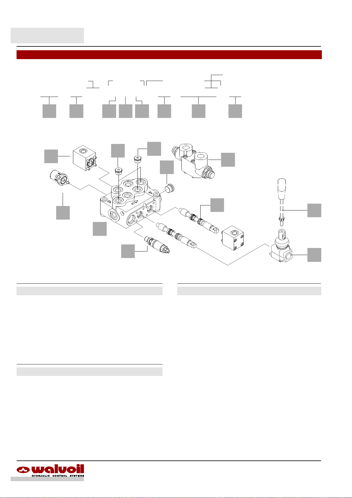
Service valves1.
All service valves need special body: contact Customer Service.
BP
BPS
P
2.
1.
VSC(JG...)
VSCT
VS
3.
Kit VS
4.
6.
VD11
Kit VD1
5.
VM(...)
VMT
VD12
Kit VM
VD13
VM(...)
VMT
42 DAT003A
Page 43

SD5
Service valves
1. Relief valve page 44
TYPE CODE DESCRIPTION
VS(G3--100) 3XCAR505113 Range 40 to 200 bar / 580 to 2900 psi
standard setting 100 bar / 1450 psi
VST 3XTAP419300 Valve blanking plug
2. Flange mounted relief valve page 45
TYPE CODE DESCRIPTION
VSC(JG2--60) 5KIT105412 Range 40 to 80 bar / 580 to 1150 psi
standard setting 60 bar / 870 psi
VSC(JG3--100) 5KIT105413 Range 63 to 200 bar / 900 to 2900 psi
standard setting 100 bar / 1450 psi
VSC(JG4--200) 5KIT105414 Range 160to250 bar /2300to 3600psi
standard setting 200 bar / 2900 psi
VSCT XTAP623282 Valve blanking plug
Kit VS 5CO2420000Mounting block kit
3. Antishock valves page 46
Cross return type, fitted with mounting block
TYPE CODE DESCRIPTION
P1(G3--100) 602001007* Block with valve on port A
P2(G3--100) 602001007* Block with valve on port B
P3(G3--100) 602001101* Block with valves on ports A and B
P(G2--60) 5CAR211 112 Single valve:range 40to 100bar /580 to
1450psi,standard setting 60bar/ 870 psi
P(G3--100) 5CAR211113 Single valve: range 80 to 200 bar / 1150
to 2900 psi, standard setting 100 bar /
1450 psi
P(G4--200) 5CAR211113 Single valve:range 180to 315 bar/ 2600
to 4600 psi, standard setting 200 bar /
2900 psi
PT XTAP526430 Valve blanking plug(forconfigurationP1,
P2)
4. Pilot check valves page 47
Fitted with mounting block
TYPE CODE DESCRIPTION
Directv type
BP1 602002020* Block with valve on port A
BP2 602002020* Block with valve on port B
BP3 602002101* Block with valves on ports A and B
BP XCAR605110 Single valve
With pre--opening
BPS1 602003005* Block with valve on port A
BPS2 602003005* Block with valve on port B
BPS3 602003105* Block with valves on ports A and B
BPS XACR605210 Single valve
BPT XTAP627300 BP and BPS valves blanking plug
5. Anti--schock+anti--cavitation valve page 49
Flange mounted type with fixed setting
(setting is referred to Q = 10 l/min -- 2.64 US gpm flow)
TYPE CODE DESCRIPTION
VM(50) 5KIT326050 Setting 50 bar / 720 psi
VM(60) 5KIT326060 Setting 60 bar / 870 psi
VM(70) 5KIT326070 Setting 70 bar / 1010 psi
VM(80) 5KIT326080 Setting 80 bar / 1150 psi
VM(90) 5KIT326090 Setting 90 bar / 1300 psi
VM(100) 5KIT326100 Setting 100 bar / 1450 psi
VM(125) 5KIT326125 Setting 125 bar / 1800 psi
VM(140) 5KIT326140 Setting 140 bar / 2050 psi
VM(160) 5KIT326160 Setting 160 bar / 2300 psi
VM(175) 5KIT326175 Setting 175 bar / 2550 psi
VM(190) 5KIT326190 Setting 190 bar / 2750 psi
VM(210) 5KIT326210 Setting 210 bar / 3050 psi
VM(230) 5KIT326230 Setting 230 bar / 3350 psi
VM(250) 5KIT326250 Setting 250 bar / 3600 psi
VM(260) 5KIT326260 Setting 260 bar / 3750 psi
VM(280) 5KIT326280 Setting 280 bar / 4050 psi
VM(300) 5KIT326300 Setting 300 bar / 4350 psi
VMT XTAP221340 Valve blanking plug
Kit VM 5CO2820020 Mounting block kit
6. Flow control valves page 50
Flow control on every section; with auxiliary inlet
TYPE CODE DESCRIPTION
VD11 2S0PP10002000 Fine regulation from 3 to 30 l/min
VD12 2S163602021 1 As VD11, one turn with detent
VD13 2S0PP10002002 12VDC proportional solenoid valve
Kit VD1 5CO2822015* Mounting block kit
NOTE -- Valve setting at points 1--2--3 are referred to 10 l/min -- 2.64 US gpm flow.
NOTE -- (*) Codes are referred to UN-UNF threads.
43DAT003A
Page 44

SD5
Services valves
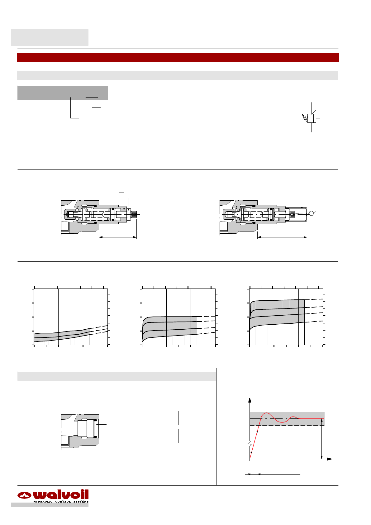
VS relief valve
It’s suggested for flow up to 25 l/min -- 6.6 US gpm, and it’s mounted on parallel body to limitate the pressure, at lower value than
main relief valve (min. gap 20 bar -- 290 psi ), on downstream section.
It’s in parallel with flow trough and it works only with single operation.
VS5 ( G 3 -- 100 )
Adjustment type (G, H)
Adjustment type
G: with screw H: valve set and locked
Wrench 10
9.8 Nm / 7.2 lbft
Wrench 17
24 Nm / 17.7 lbft
Wrench 19
24 Nm / 17.7 lbft
Pressure setting in bar
(standard 100 bar / 1450 psi)
Allen wrench 3
32.5
1.28
Max.
A1 B1 A2 B2
T
P
100
120
1750
1450
Performance data
Spring nr. 3 (blue band)
2 4 6
400
(bar)
300
200
Pressure
100
0
0 10 20 30
Flow
(US gpm)
(l/min)
VST: valve blanking plug
Allen wrench 6
42 Nm / 31 lbft
(psi)
4500
3000
1500
4
0.16
(% DP)
105%
95%
90%
Pressure
10%
Response time
0,08”
RESPONSE TIME
100 bar
1450 psi
Time (”)
44 DAT003A
Page 45
SD5
\
Service valves
VSC relief valve
It’sflange mounted onparallel body onthe oppositeside of workingports, the functionto limitthe pressure, atlower value thanmain
relief valve (min. gap 20 bar -- 290 psi) on downstream sections.
It’s in parallel with flow through line and it works only with single operation.
It needs a dedicated body with extra machining: for production requirements, the block (2) is flanged (1) before the final honing of
spool hole, while the valve (3) is mounted during final assembling phase.
For information contact Customer Service.
1
23
VSC ( J G 3 -- 100 )
Adjustable spring type (2, 3, 4).
Adjustment type (G, H)
T
max. 51.5
2.03
Standard setting in bar (for value see page 43)
LC
13.5
0.53
32
1.26
7.5
54.5
2.15
Allen wrench 4
6.6 Nm / 4.9 lbft
0.30
A1 B1 A2 B2
P
120
1750
100
1450
Ex.: SD5/2--P(JG3--120)/18L/VSC(JG3--100)/18L/AET
T
NOTE -- For valve performance see page 10.
45DAT003A
Page 46

SD5
Service valves
P anti--shock valves with cross return
Cast iron block with antishock valves.
P 1 ( D 3 -- 100 ) -- SAE
Standard setting in bar
(for value see page 43)
Spring type (2, 3, 4).
Adjustment with blind nut (D).
1 mounted on port A.
2 rmounted on port B.
3 mounted on ports A and B.
P1 P2 P3
A B A B A B
100
1450
100
1450
100
1450
100
1450
P1 configuration
Example of pressure on port A and port B to tank
A B A B
Allen wrench 8
42 Nm / 31 lbft
P T PT
Performance data
Spring nr. 2 (green band)
5 10 15
400
(bar)
300
200
Pressure
100
(US gpm)
(psi)
4500
3000
1500
Wrench 27
42 Nm / 31 lbft
Allen wrench 5
Wrench 21
24 Nm / 17.7 lbft
(bar)
Pressure
P3 configuration
Example of pressure on port B and port A to tank
Spring nr. 3 (blue band)
5 10 15
400
300
200
100
(US gpm)
(psi)
4500
3000
1500
0
0 20 40 60
Flow
Spring nr. 4 (red band)
5 10 15
400
(bar)
300
200
Pressure
100
0
0 20 40 60
Flow
(l/min)
(l/min)
(US gpm)
(psi)
4500
3000
1500
0
0 20 40 60
Flow
(l/min)
Time response
(% DP)
105%
95%
90%
Pressure
10%
0,12”
TIME RESPONSE
120 bar
1750 psi
Time (”)
46 DAT003A
Page 47

BP, BPS pilot check valves
Cast iron block with pilot check valves.
SD5
Service valves
BP1 BP2 BP3
BPS 1 -- SAE
1 mounted on port A.
2 mounted on port B.
3 mounted on ports A and B.
BP direct type
BPS with pre--opening
BP1 configuration
Example of pressure on port A and port B to tank
A B
Wrench 27
42 Nm / 31 lbft
P T
Example of pressure on port B and port A to tank
A B
BPS1 BPS2 BPS3
A B
Example of pressure on port A and port B to tank
Wrench 27
42 Nm / 31 lbft
Wrench 19
42 Nm / 31 lbft
Example of pressure on port B and port A to tank
A B A B
BP3 configuration
A B
P T
BA
Performance data
BP valve pressure drop
5 10 15
40
(bar)
30
20
Pressure
10
0
0 20 40 60
Flow
PT
(l/min)
(US gpm)
(psi)
450
300
150
Type
BP
BPS 1 : 16
With
pre-- opening
Pilot ratio
/
47DAT003A
Main
1 : 5.3
1 : 3.2
BPS valve pressure drop
5 10 15
40
(bar)
30
20
Pressure
10
0
0 20 40 60
Flow
PT
(US gpm)
(psi)
450
300
150
(l/min)
Page 48

SD5
Service valves
P antishock valves with cross return
36
P3 configuration
valve block
14
14
0.55
19
0.75
50
1.97
26
1.02
1.42
BP3 configuration
valve block
0
58
2.28
30
1.18
19
0.75
16.521
0.652.360.83
60
128
3.46
5.04
20 88
0.79
21.5
0.85
56.5
2.22
97
93
3.66
= =
14.3
0.56
4.79
3.82
121.6
= =
= =
0.91
L1 special lever box
code: 5LEV105050
1.18 1.46 1.06 0.22
37 273023 5.5
Standard lever box
Example of extra machining on directional valve body
2828 9 18.5
0.73
16.5
0.65
2737.5
1.06
Milled surface with
fixing threaded holes
1.10
0.35
1.10
P3 configuration BP3, BPS3 configuration
62.5
2.46
1.6
M5
1.48
10
0.39
13
0.51
48 DAT003A
Page 49

SD5
Service valves
VM anti--shock and anti--cavitation
They are flange mounted on the opposite side of working ports, connected in parallel with A and B ports and with outlet on T port.
It needs a dedicated body with extra machining: for production requirements, the block (2) is flanged (1) before the final honing of
spool hole, while the valve (3) is mounted during final assembling phase.
For information contact Customer Service.
1
23
VM 1 (100)
1 mounted on port A
2 mounted on port B
3 mounted on ports A and B
28.5
1.12
41.5
1.63
2 75
0.08
Allen wrench 10
24 Nm / 17.7 lbft
Valve setting in bar
VM1 configuration
2.95
Allen wrench 6
24 Nm / 17.7 lbft
Allen wrench 4
6.6 Nm / 4.9 lbft
VM1 VM2 VM3
100
1450
100
12
45
(l/min)
A B
(US gpm)
(psi)
4500
3000
1500
A BA B
T
1450
100
1450
TT
100
1450
Pressure--flow diagram
4 8
350
(bar)
300
250
200
150
14.5
0.57
Pressure
100
50
0
0 10 20 30 40
Flow
49DAT003A
Page 50

SD5
Service valves
VD1 flow control valves
Block with pressure compensated 3--way flow control valve, to be flange mounted on body with parallel circuit.
The cavity is oriented toward lever side.
The flow is regulated on every working section while the exceeding flow goes to tank: max. regulated flow 30 l/min -- 7.9 US gpm
(with inlet on P1 port).
It needs a dedicated body with extra machining: for production requirements, the block (2) is flanged (1) before the final honing of
spool hole, while the valve (3) is mounted during final assembling phase.
For information contact Customer Service.
1
T
3
P1
2
Manual control
VD11: continuous fine regulation
13.5
0.53
33.5
1.32
447711.5
0.45
Ex.: SD5/2--P(JG3--120)VD11/18L/18L/AET--SAE
3.03
1.73
VD12: one turn with detent handknob regulated
P1
Hydraulic circuit
A1 B1
P
120
1750
C
R
Ex.: SD5/2--P(JG3--120)VD12/18L/18L/AET--SAE
94.5
3.72
50 DAT003A
Page 51

VD1 flow control valves
VD13 with proportional solenoid control
SD5
Service valves
ISO4400 connection
(needs C02 connector,
see page. 62)
13.5
0.53
33.5
0.14
94.57711.5
0.45 3.03
3.72
Ex.: SD5/2--P(JG3--120)VD13/18L/18L/AET
VD13 proprtional solenoid flow control valve connection
It’s shows a configuration with push--button panel type UPA.
For information contact Customer Service.
Emergency
push--button
Potentiometer for
valve adjustment
Hydraulic circuit
P
120
1750
P1
C
R
Solenoid operating feautures
Nominal voltage : 12 VDC. .. . . .. . .
Power rating : 28 W. . . . . . . . . . . .
Duty cycle : 100%. . . . . . . . . . . . . .
A1 B1
STOP
Push--button panel type:
UPA12/100/SC01B22
Performance data
Pressure--flow diagram
Qin = 45 l/min
1000 2000 3000
40
(l/min)
30
20
10
Priority flow
0
30 90 150 210 270
Pressure (bar)
(psi)
(US gpm)
9
6
3
To battery
ISO4400
connector
Flow regulation diagram
Qin = 45 l/min (12 US gpm) -- P = 100 bar (1450 psi)
0,3 0,6 0,9 1,2 Current (A)0
40
(l/min)
30
20
Priority flow
10
0
F
0,0 0,5 1,0 1,5 2,0 2,5
3 6 9 12 15 18
0
Y
(US gpm)
9
J
6
3
(n.of turn)
(n.of clicks)
F
VD11 flow control valve
Y
VD12 flow control valve
J
VD13 flow control valve
51DAT003A
Page 52

SD5
52 DAT003A
Page 53

Other executions
SD5/1-N page 54. . . . . . . . . . . . . . . . . . . . . . . . . . . . . . . . . . . . . . . . . . . . . . . . . . .
It’s available only with one working section and it can be used in hydraulic circuits where power beyond doesn’t required.
SD5/1-D page 55. . . . . . . . . . . . . . . . . . . . . . . . . . . . . . . . . . . . . . . . . . . . . . . . . . .
It’s available only with one working section and it can be used in hydraulic circuits where power beyond is required.
SD5
SD5-S: with series circuit page 56. . . . . . . . . . . . . . . . . . . . . . . . . . . .
Availablefrom 2 to 6 sections,it can be used in systems wich onedownstream
sectionfrom seriesconnection mustwork withupstream onesatthe sametime.
It’s not available the power beyond circuit.
On the same body are possible more than one connection.
SD5-SP: with tandem circuit pag. 58.. . . . . . . . . . . . . . . . . . . . . . . .
Available from 2 to 6 sections, for security reasons it can be used in systems
which isrequired to prohibit engagementof downstream sections from tandem
connection when the upstream sections are working.
On the same body are possible more than one connection.
53DAT003A
Page 54
SD5/1-- N
Dimensional data
105.5
4.15
14 73
0.55
1.341.79
186
7.32
45.5 34
46
1.81
0.96
2.87
273024.5
1.18 1.06
M8
8.5
0.33
81
103
3.19
4.06
51
2.01
20
11.5
0.45
0.79
63.5 3
2.50 0.12
45
1.77
24.5
0.96
Position 1
15°
Pos. 0
15°
Position 2
90
3.54
Standard threads
PORTS
BSP
(ISO228/1)
Inlet P G 3/8 3/4--16 UNF--2B (SAE 8) M18x1.5
Ports A and B G 3/8 9/16 --18 UNF--2B (SAE 6) M18x1.5
Outlet T G 3/8 3/4--16 UNF--2B (SAE 8) M18x1.5
UN--UNF
(ISO 11926--1)
METRIC
(ISO 262)
Hydraulic circuit Performance data
A1 B1
P
120
1750
Ex.: SD5/1--N(JG3--120)/18L--SAE
Code: 102110118
15
(bar)
10
T
5
Pressure
0
Pressure drop curve
5 10 15
P®A(B)
P®T
A(B)®T
0 15 30 45 60
Flow
(l/min)
(US gpm)
200
(psi)
150
100
50
54 DAT003A
Page 55

SD5/1-- D
Dimensional data
102
13 73
0.51
1.341.79
186
7.32
45.5 34
46
1.81
0.93 1.18
4.02
2.87
273023.5
1.06
M8
8.5
0.33
81
103
4.06
3.19
51
2.01
20
11.5
0.45
0.79
63.5 3
2.50
45
1.77
24.5
0.96
0.12
Position 1
15°
Pos. 0
15°
Position 2
90
3.54
Standard threads
PORTS
BSP
(ISO228/1)
Inlet P and power beyond C G 3/8 3/4--16 UNF--2B (SAE 8) M18x1.5
Ports A and B G 3/8 9/16 --18 UNF--2B (SAE 6) M18x1.5
Outlet T G 3/8 3/4--16 UNF--2B (SAE 8) M18x1.5
UN--UNF
(ISO 11926--1)
METRIC
(ISO 262)
Hydraulic circuit Performance data
A1 B1
P
120
1750
Ex.: SD5/1--D(JG3--120)/18L--SAE
Code: 102160032
20
T
C
(bar)
15
10
Presure
5
0
Pressure drop curve
5 10 15 (US gpm)
P®A(B)
P®C
A(B)®T
0 15 30 45 60
Flow
(l/min)
200
(psi)
150
100
50
55DAT003A
Page 56

SD5-- S
TYP
E
TYP
E
Dimensional data
E
12.5
0.49
34
1.34
186
7.32
45.5
1.79
45
1.77
23
0.91
30 37
1.18
F
1.46
27
1.06
M 8
24.5
0.96
8.5
0.33
81
103
4.06
3.19
51
2.01
11.5
0.45
20
0.79
63.5 3
2.50
45
1.77
90
3.54
0.12
Position 1
15°
Pos. 0
15°
Position 2
SD5/2--S
SD5/3--S
SD5/4--S
E F Weight
mm in mm in kg lb
137.5 5.41 110 4.33 5.2 11.4
174.5 6.87 147 5.79 6.9 15.2
211.5 8.33 184 7.24 8.1 17.9
SD5/5--S
SD5/6--S
E F Weight
mm in mm in kg lb
248.5 9.78 221 8.70 10.1 22.3
285.5 11.2 258 10.2 11.7 25.8
Standard threads
PORTS
BSP
(ISO228/1)
Inlet P G 3/8 3/4--16 UNF--2B (SAE 8) M18x1.5
Ports A and B G 3/8 9/16--18 UNF--2B (SAE 6) M18x1.5
Outlet T G 1/2 3/4--16 UNF--2B (SAE 8) M22x1.5
56 DAT003A
UN--UNF
(ISO 11926--1)
METRIC
(ISO 262)
Page 57
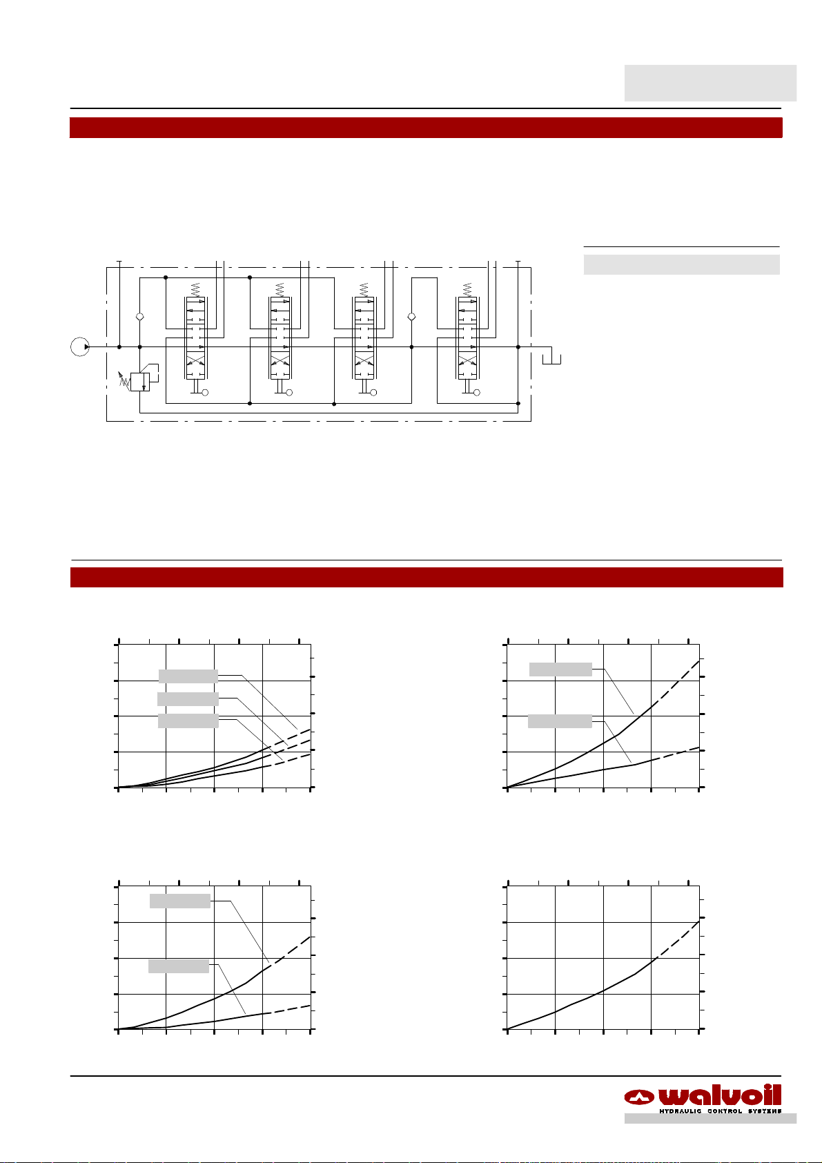
SD5-- S
Hydraulic circuit
The description ofSD5 valve with series circuit is marked withletter “S” and one figure wich indicate thedownstream sections from
series connection.
P
(bar)
A1 B1 A2 B2
A3 B3 A4 B4
Available body kits
CODE DESCRIPTION
5KC1157040 SD5/2--S1
5KC1257000 SD5/3--S1
5KC12D7000 SD5/3--S1+1
T
5KC1287000 SD5/4--S1
5KC12E7000 SD5/4--S1+1+1
5KC1327003 SD5/5--S1
120
1750
Ex.: SD5/4--S1(JG3--120)/18L/18L/18L/18L--SAE
5KC1077001 SD5/5--S1+1+1+1
5KC13A7000 SD5/5--S2+1
5KC1367000 SD5/6--S1
Include boby, seals and load check
valves.
Code: 1024B0028
Performance data
Pressure drop P®T Pressure drop P®A(B)
5 10 15
40
30
20
Pressure
10
6 sections
4sectionis
2 sections
(US gpm)
(psi)
450
300
150
(bar)
Pressure
40
30
20
10
5 10 15
P®A6(B6)
P®A1(B1)
(US gpm)
(psi)
450
300
150
0
0 15 30 45 60
Flow
Pressure drop A(B)®T
5 10 15
40
(bar)
Pressure
30
20
10
0
A1(B1)®T
A6(B6)®T
0 15 30 45 60
Flow
(l/min)
(l/min)
(US gpm)
(psi)
450
300
150
0
0 15 30 45 60
Flow
Pressure drop
between port A(B) before series connection and port A(B) after
5 10 15
40
(bar)
30
20
Pressure
10
0
0 15 30 45 60
Flow
57DAT003A
(l/min)
(US gpm)
(psi)
450
300
150
(l/min)
Page 58

SD5-- SP
TYP
E
TYP
E
Dimensional data
12,5
0.49
34
1.34
186
7.32
45.5
1.79
Power beyond
E
F
21
0.81
24.5
0.96
8.5
0.33
81
103
3.19
4.06
51
2.01
63.5 3
2.50
45
1.77
0.12
45
1.77
SD5/2--SP1
SD5/3--SP2
SD5/4--SP3
0.91
1.18
1.46
1.06
30 3723 27
E F Weight
mm in mm in kg lb
137.5 5.41 110 4.33 4.8 10.6
174.5 6.87 147 5.79 6.7 14.8
211.5 8.33 184 7.24 8.1 17.6
M 8
11.5
0.45
20
0.79
SD5/5--SP4
SD5/6--SP5
SD5/7--SP6
Posizione 1
15°
Pos. 0
15°
Posizione 2
90
3.54
E F Weight
mm in mm in kg lb
248.5 9.78 221 8.70 10.2 22.5
285.5 11.2 258 10.2 11.3 24.9
322.5 13.1 295 11.6 12.7 28
Standard thread
PORTS
BSP
(ISO228/1)
Inlet P and power beyond C G 3/8 3/4--16 UNF--2B (SAE 8) M18x1.5
Ports A and B G 3/8 9/16 --18 UNF--2B (SAE 6) M18x1.5
Outlet T G 3/8 3/4--16 UNF--2B (SAE 8) M18x1.5
58 DAT003A
UN--UNF
(ISO 11926--1)
METRIC
(ISO 262)
Page 59
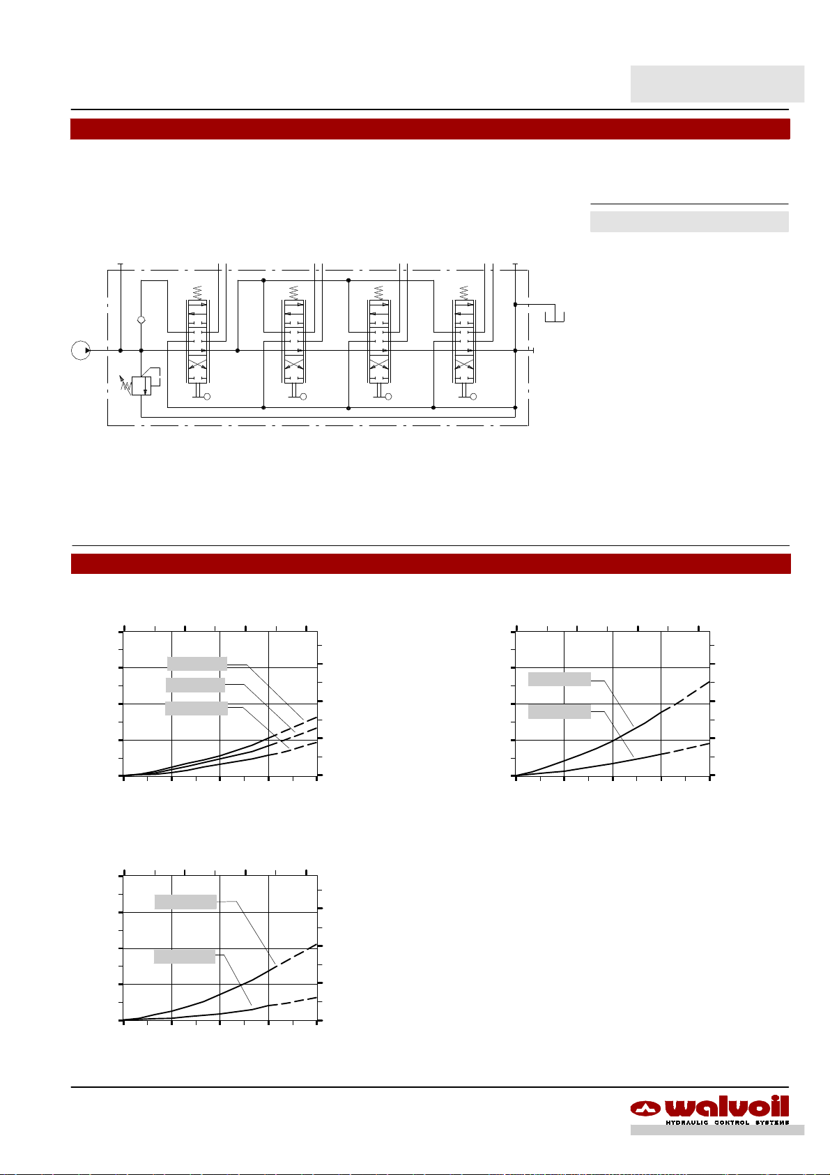
SD5-- SP
Hydraulic circuit
The description of SD5 valve with tandem circuit is marked with letters “SP” and one figure wich indicate the downstream sections
from tandem connection.
Available body kits
A1 B1 A2 B2
A3 B3 A4 B4
T
P
120
1750
Ex.: SD5/4--SP3(JG3--120)/18L/18L/18L/18L/AET--SAE
Code: 1024A0019
CODE DESCRIPTION
5KC1187000 SD5/2--SP1
5KC12G7000 SD5/3--SP2
5KC1307000 SD5/4--SP1
5KC12H7000 SD5/4--SP1+2
5KC12I7000 SD5/4--SP2+1
5KC1297000 SD5/4--SP3
5KC13D7000 SD5/5--SP2+2
5KC1347000 SD5/5--SP3+1
5KC1337000 SD5/5--SP4
5KC1397000 SD5/6--SP3+1
5KC13Y7000 SD5/6--SP3+2
5KC1377000 SD5/6--SP5
5KC13J7000 SD5/7--SP3+1
5KC13G7000 SD5/7--SP4
5KC13L7000 SD5/7--SP5+1
5KC13F7000 SD5/7--SP6
Include boby, seals and load check
valve.
Pressure drop P®T Pressure drop P®A(B)
5 10 15
40
(bar)
30
20
Pressure
10
0
0 15 30 45 60
6 sections
4sections
2 sections
Flow
Pressure drop A(B)®T
5 10 15
40
(bar)
30
20
Pressure
10
A1(B1)®T
A6(B6)®T
(l/min)
(US gpm)
(psi)
450
300
150
(US gpm)
(psi)
450
300
150
Performance data
5 10 15
40
(bar)
30
P®A6(B6)
20
Pressure
P®A1(B1)
10
0
0 15 30 45 60
Flow
(US gpm)
(psi)
450
300
150
(l/min)
0
0 15 30 45 60
Flow
(l/min)
59DAT003A
Page 60

SD5
(*)--Onlyforseriescircuit
.
Installation and maintenance
The SD5 valve is assembled and tested as per the technical specification of this catalog.
Before the final installation on your equipment, follow the below recommendations:
-- thevalve can be assembled inany position, in order to prevent body deformationand spool sticking mount the product on aflat
surface;
-- inordertoprevent thepossibilityofwater enteringtheleverbox andspool controlkit,do notusehigh pressurewash downdirectly
on the valve;
-- prior to painting, ensure plastic port plugs are tightly in place.
A2
A1
B1
B2
T
C
P
Power beyond configuration
Fitting tightening torque -- Nm / lbft
THREADS TYPE P and C ports A and B ports T port
BSP (ISO 228/1) G 3/8 G 3/8
With O--Ring seal 35 / 25.8 35 / 25.8
With copper washer 40 / 29.5 40 / 29.5
With steel and rubber washer 30 / 22.1 30 / 22.1
UN--UNF (ISO 11926--1) 3/4--16 UNF--2B (SAE 8) 9/16--18 UNF--2B (SAE 6) 3/4--16 UNF--2B (SAE 8)
With O--Ring seal 40 / 29.5 30 / 22.1 30 / 22.1
METRIC (ISO 262) M18 x 1.5 M18 x 1.5
With O--Ring seal 35 / 25.8 35 / 25.8
With copper washer 40 / 29.5 40 / 29.5
With steel and rubber washer 40 / 29.5 40 / 29.5
G 3/8 (G 1/2*)
35 / 25.8(50 / 36.9*)
40 / 29.5 (50 / 36.9*)
30 / 22.1 (50 / 36.9*)
M18 x 1.5 (M22x1.5*)
35 / 25.8 (50*)
40 / 29.5 (50*)
40 / 29.5 (50*)
NOTE -- These torque are recommended.Assembly tightening torque depends on many factors, includinglubrication, coating and
surface finish. The manufacturer shall be consulted.
60 DAT003A
Page 61

Positioner kit
InabilitytobuildpressureonAandB
Load check valve
SD5
Installation and maintenance
O--Ring seal 15,88x2,62 -- code: 4GUA115926
Note
In case of assistance follw this assembling procedure
-- fit the O--Rimg seal in seat on lever side;
-- fit the spool from the opposite side and till it is possible to
fit the other O--Ring seal;
-- position the spool in center.
Body
Sealing edge
Lever
pivot box
Spool
Main relief valve
Normally spools are interchangeable. Verify the smoothness during the assembly
NOTE -- All articulated parts inside cap, lever box and mechanical joystick are lubricated with synthetic base grease grade NLGI2
Malfunction Cause Remedy
External leakage pivot box lever or
control kit side.
Excessive internal leakage on A and B
ports.
Dropping load during transition while
raising
Inability to build pressure on A and B
ports.
Worn spool seal due to mechanical
actuation or high back pressure.
Increase clearance between spools and
body due to high wear.
High leakage on the load check valve.
Locate the leakage and replace the seal.
Check back pressure level.
Replace the directional control valve and
check the oil contamination level.
Remove the load check valve and clean
the seat, verifing it’s not dented.
Pressure relief valve blocked open. Remove and clean or replace the valve.
Low pump pressure and flow. Check the pump and circuit.
61DAT003A
Page 62

SD5
Accessories
Optional connectors
Type C01 code: 2X1001020
2P+T, according to DIN43650.
31.5
1.24
31.5
1.24
40.5
23.5
0.93
1.59
PG09
Type C05 code: 2X1001080
3P+T according to ISO4400 /DIN43650 --A.
With bridgerectifier, touse with VAC supply.
53
2.09
30
1.18
54.2
2.13
71
2.79
Type C02 code: 2X1001010
2P+T according to ISO4400 / DIN43650 --A
33
1.30
50
1.97
2
30
1.18
1
PG09
Type C06 code: 5CON002
3P+T according to DIN43650--C
27
38.8
1.53
21.2
0.83
1.06
15
28
1.10
Type C03 code: 2X1001030
3P+T according to ISO4400 / DIN43650 --A
28.5
1.12
14
0.55
42.5
28
1.10
1.67
Type C07 code: 5CON001
2 poles, type Packard
0.59
15
0.59
PG07
40.5
1.59
1
PG09
21.3
0.85
Type C11 code: 5CON006
4P according to VDE0660--0110
23
37
13
Æ
16
PG07
PG09
Type C17 code: 5CON005
2 poles, type Packard
47
1.85
24
0.95
62 DAT003A
Type C19 code: 5CON130030
2P, type Deutsch DT06 --2S
28.4
1.120.59
15
Page 63

SD5
Note
Type
Poles Nominal voltage
C01 2P + T 250 VAC / 300 VDC 10 A max.1.5 mm2/ max.0.0023 in
C02 2P + T 250 VAC / 300 VDC 10 A max.1.5 mm2/ max.0.0023 in
C03 3P + T 250 VAC / 300 VDC 10 A max.1.5 mm2/ max.0.0023 in
C05 3P + T 230 VAC 1.5 A max.1.5 mm2/ max.0.0023 in
C06 3P + T 250 VAC / 300 VDC 6 A max.0.75 mm2/ max.0.00116 in
C07 2P / 20 A 1--2.5 mm2/ 0.00155--0.0038 in
C11 4P 50 VAC / 120 VDC 6 A 0.14--0.5 mm2/ 0.00022--0.00077 in24--7.5 mm / 0.16--0.29 in IP65
C17 2P / 20 A 1--2 mm2/ 0.00155--0.0031 in
C19 2P / 13 A 1--2 mm2/ 0.00155--0.0031 in
Nominal
current
Permitted conductor
section range
Permitted cable
diameter range
2
2
2
2
2
2
2
6--8 mm / 0.24--0.31 in IP65
6--8 mm / 0.24--0.31 in IP65
6--8 mm / 0.24--0.31 in IP65
6--8 mm / 0.24--0.31 in IP65
2
6--8 mm / 0.24--0.31 in IP65
2.8--3.5 mm / 0.11--0.14 in IP67
2.8--3.5 mm / 0.11--0.14 in IP67
2.2--3.5 mm / 0.088--0.14 in IP67
SD5 valve can be supplied with one coat of black paint (CVN configuration).
Description example: SD5/2 --P(JG3--120)/18L/18L/AET--SAE--<CVN>
Weather
protection
Note
NOTE -- For different colour consult Customer Service.
63DAT003A
Page 64

WALVOIL S.P.A.
42100 REGGIO EMILIA · ITAL Y· VIA ADIGE, 13/D
E--MAIL: INFO@WALVOIL.COM · HTTP: //WWW.WALVOIL.COM
TEL. +39.0522.932411· FAX +39.0522.300984
SALES DEPARTMENT
TEL. +39.0522.932555 · FAX +39.0522.932455
D1409808I
DAT003A
 Loading...