

Waltron 9065 User Manual
EXPERTS IN WATER CHEMISTRY SINCE 1903
9065 Luminescent Dissolved Oxygen Analyzer
User Manual
Revision 2.05

Waltron Customer Commitment
1
Waltron User Manual
9065 Luminescent Dissolved Oxygen Analyzer
WALTRON CUSTOMER COMMITMENT
This instruction manual is a technical guide to aid the customer in the set-up, operation, and
maintenance of their new Waltron measuring system. Waltron provides continuous product
improvement and reserves the right to make any modifications to the information contained
herein without notice.
Copyright © Waltron Bull & Roberts, LLC, 2016
All Rights Reserved
Technical questions concerning this product should be addressed to:
Waltron Technical Service Department
Flemington, New Jersey
Phone: (908)-534-5100
Fax: (908)-534-5546
www.waltron.net
Please be ready to provide the following information:
Date analyzer was purchased
Analyzer model and serial number
Recent maintenance history
Calibration slope values and detailed description of problem
Waltron’s technical expertise and extensive experience provides personalized solutions to the
water quality industry. It is Waltron’s commitment to provide the customer with timely and
accurate technical service and support.
Waltron fully expects the customer to be satisfied with the quality, performance, and cost of this
product.
If there are any questions or concerns regarding this product, please feel free to contact Waltron
at (908)-534-5100.
Thank you for choosing Waltron!
Please note the Waltron mailing and shipping address:
Waltron Bull & Roberts, LLC
25 Minneakoning Road, Suite 101
Flemington, NJ 08822

Safety
2
Waltron User Manual
9065 Luminescent Dissolved Oxygen Analyzer
SAFETY
Please observe proper safety and handling precautions when installing, operating, maintaining,
and servicing this product. The following should be noted and adhered to:
Read and understand manual before working with analyzer.
Pay special attention to warning labels on enclosures, containers, packages and
chemicals.
Only qualified personnel should be involved in the installation, operation, and servicing
of the analyzer.
Follow safety precautions when operating analyzer in conditions of high pressure and/or
temperature.
Keep analyzer chemicals away from heat and extreme temperatures. Reagent powders
must be kept dry.
Follow all regulations and warning labels when disposing of chemicals. Do not mix
chemicals.
To obtain analyzer safety information or Safety Data Sheets (SDS), please contact Waltron or
visit the website at www.waltron.net .

Warranty Agreement
3
Waltron User Manual
9065 Luminescent Dissolved Oxygen Analyzer
WARRANTY AGREEMENT
If, within one year from the date of shipment, the customer experiences any equipment defects or
is not satisfied with the analyzer manufacturing, Waltron will repair, or at its option, replace any
defective part(s) free of charge. This warranty requires that the defective part(s) be returned to
Waltron with shipping charges prepaid.
At Waltron discretion, a Technical Service Specialist may be sent out to repair or replace the
defective part(s) on location. Traveling time and expenses of the Technical Service Specialist is
at the customer’s expense.
Equipment sent to Waltron must be appropriately packaged and the following information must
be provided prior to returning to Waltron:
The Return Authorization (RA) number assigned to the customer by the Waltron
Technical Service Department
Customer name, address and department
Name and telephone number of the individual responsible for returning items for repair
Brief problem description
Ship to Waltron service center:
Waltron Bull & Roberts, LLC
25 Minneakoning Road, Suite 101
Flemington, NJ 08822
The Waltron Warranty Agreement:
Covers expendable sensors for one month after shipment and reusable electrodes for six
months after shipment.
Does not apply to damages occurred during shipping.
Warranty will be nullified if goods have been used for purposes other than those for
which they are intended or if any seal has been removed, broken or tampered with or if
the Waltron trademark or serial number has be removed, defaced, or altered.
Does not cover expendable supply items such as reagents, tubing and electrolytes.
Does not cover misuse or mistreatment by the user.
Does not cover previous repair or alteration by unauthorized individuals.
Waltron does not assume responsibility for contingent liability through alleged failure or failures
of products or product accessories.

Checklist of Materials
4
Waltron User Manual
9065 Luminescent Dissolved Oxygen Analyzer
CHECKLIST OF MATERIALS
In order to ensure customer satisfaction, Waltron does its best to provide adequate and
timely packaging and shipping services. Please perform the following after receiving a
shipment:
Inspect all shipping containers upon receipt and record any visible damage. If there are
any outward signs of damage, please retain all containers and packages for inspection by
carrier. Please retain all packing material so that it can be used for future moving and
shipping needs.
Check all items received against those on the packing list. Chemicals are usually shipped
in a separate package and will be itemized accordingly.
Verify that the number of packages received agrees with the packing list and shipping
papers.
Notify both Waltron and the carrier if any problems occur.
Important Notice:
All analyzers are inspected and tested prior to shipment.
In normal use, the unit should require only minor maintenance and should operate
correctly and without fault over a long period of time.
Please note that if electronic components need to be replaced, it may be necessary to
adjust and/or calibrate the analyzer.
Failure to carry out correct maintenance procedures may result in inaccurate analyzer
readings.

Table of Contents
5
Waltron User Manual
9065 Luminescent Dissolved Oxygen Analyzer
TABLE OF CONTENTS
Waltron Customer Commitment .............................................................. 1
Safety ......................................................................................................... 2
Warranty Agreement ................................................................................. 3
Checklist of Materials ............................................................................... 4
Table of Contents ..................................................................................... 5
List of Figures ........................................................................................... 7
List of Tables ............................................................................................. 8
1 Overview .............................................................................................. 9
1.1 Technical Specifications............................................................................................... 9
1.2 Intended Use ..............................................................................................................10
1.3 Safety .........................................................................................................................11
1.3.1 Symbols ...............................................................................................................11
1.3.2 Precautionary Measures and Safety Instructions .................................................11
2 Introduction ....................................................................................... 12
2.1 Analyzer Overview ......................................................................................................12
2.2 Sensor ........................................................................................................................13
2.3 Coatingholder .............................................................................................................13
2.4 O2 Measurement Principle ..........................................................................................13
3 Installation ......................................................................................... 15
3.1 Content of the Delivery ...............................................................................................15
3.2 Pre-Installation ............................................................................................................15
3.3 Mounting the 9065 ................................................................ ......................................16
3.4 Assembling the Sensor ...............................................................................................17
3.5 Sample Connections ...................................................................................................18
3.6 Electrical Connections ................................................................................................19
3.6.1 Transmitter Connections ......................................................................................19
3.6.2 Power Cable ........................................................................................................19
3.6.3 RS-232 Communication Cable .............................................................................20
3.6.4 Sensor Cable .......................................................................................................20
3.6.5 I/O Cable .............................................................................................................20
3.7 Preparation and Start-Up ............................................................................................21
4 User Interface .................................................................................... 22
4.1 Control Buttons ...........................................................................................................22
4.2 Display Screen ............................................................................................................23
4.3 Operating Modes ........................................................................................................23
4.4 User Level ..................................................................................................................24
4.5 Configuration ..............................................................................................................25
4.5.1 Units ....................................................................................................................25
4.5.2 Info ......................................................................................................................26
4.5.3 Date .....................................................................................................................26

Table of Contents
6
Waltron User Manual
9065 Luminescent Dissolved Oxygen Analyzer
4.5.4 Time ....................................................................................................................26
4.5.5 Language .............................................................................................................26
4.5.6 Contrast ...............................................................................................................26
4.5.7 Sensor Settings ...................................................................................................26
4.5.8 Sample Application ..............................................................................................27
4.5.9 Analog Outputs ....................................................................................................27
4.5.10 Alarm Settings .....................................................................................................28
4.5.11 Alarm Outputs ......................................................................................................29
5 Operation ........................................................................................... 31
5.1 General Information ....................................................................................................31
5.2 Measurement ..............................................................................................................31
5.3 Local and Remote Operation ......................................................................................31
5.4 Data Logbook .............................................................................................................31
6 Calibration ......................................................................................... 33
6.1 Calibration of the Temperature Sensor .......................................................................33
6.2 Calibrating the O2 Sensor ...........................................................................................33
6.2.1 Calibration Frequency ................................ ..........................................................33
6.2.2 One point Calibration ...........................................................................................33
6.2.3 Calibration with Two Gases .................................................................................36
6.2.4 Check Calibration ................................................................................................38
6.2.5 Calibrating the Analog Outputs ............................................................................39
7 Cleaning and Maintenance ............................................................... 40
7.1 Inspection ...................................................................................................................40
7.2 Cleaning .....................................................................................................................40
8 Troubleshooting and Repair ............................................................. 41
8.1 Troubleshooting ..........................................................................................................41
8.2 Alarm Messages .........................................................................................................41
8.3 Repair and Maintenance .............................................................................................42
8.3.1 Replacing the Coating Holder ..............................................................................42
9 Deactivating, Storage and Transport ............................................... 44
9.1 Deactivating ................................................................................................................44
9.2 Storage .......................................................................................................................44
9.3 Transport ....................................................................................................................44
10 Spare Parts ........................................................................................ 45
Appendix A: Formulas ............................................................................ 47
Appendix B: Software Structure ............................................................ 48

List of Figures
7
Waltron User Manual
9065 Luminescent Dissolved Oxygen Analyzer
LIST OF FIGURES
Figure 2.1: Analyzer overview. ................................................................................... 12
Figure 2.2: 25 mm Sensor. .......................................................................................... 13
Figure 2.3: 9065 Coatingholder. ................................................................................. 13
Figure 2.4: Luminescence in the absence of oxygen (1) and in the presence of
oxygen (2). ................................................................................................................... 14
Figure 2.5: Optical sensor depiction. ....................................................................... 14
Figure 3.1: Dimensions of the 9065 mounting plate for wall mounting. ................. 16
Figure 3.2: Dimensions of the 9065 sensor mounting bracket. .............................. 16
Figure 3.3: Fitting the sensor into the flowcell. ........................................................ 17
Figure 3.4: Sensor orientation relative to flow direction. ........................................ 17
Figure 3.5: Sample Connections. ............................................................................... 18
Figure 3.6: Sample Connection Dimensions. ........................................................... 18
Figure 3.7: Connections to the Transmitter. ................................ ............................. 19
Figure 3.8: An example of the I/O connections. ....................................................... 21
Figure 4.1: Transmitter with display screen and user interface buttons. ............... 22
Figure 4.2: Main screen with the analyzer in stand-by mode. ................................. 23
Figure 4.3: Main screen with one sensor connected. .............................................. 24
Figure 4.4: Main screen with two sensors connected. ............................................. 24

List of Tables
8
Waltron User Manual
9065 Luminescent Dissolved Oxygen Analyzer
LIST OF TABLES
Table 3.1: Connections to the Transmitter. ............................................................... 19
Table 3.2: Connector 1: Power supply range: 90V AC – 230V AC........................... 19
Table 3.3: Connector 1: Power supply 24V DC. ........................................................ 19
Table 3.4: Connector 2: RS-232 communication. ..................................................... 20
Table 3.5: Connector 3 and 4 (Sensor 1 and 2): Sensor communication. .............. 20
Table 3.6: Connector 5: I/O Cable. ............................................................................. 20
Table 4.1: Configurable sensor settings. .................................................................. 26
Table 4.2: Configurable settings for the analog outputs. ........................................ 28
Table 4.3: Configurable Alarm Settings. ................................................................... 29
Table 4.4: Alarm Output Summary............................................................................. 30
Table 10.1: Spare Parts Listing. ................................................................................. 45

Overview
9
Waltron User Manual
9065 Luminescent Dissolved Oxygen Analyzer
Range
[ppb]
0.0 to 2,000
[µg/l]
0.0 to 2,000
[ppm]
0.00 to 2.00
[%] O2
0.000 to 4.180
[% a.s.]
0.00 to 20.0
[mg/l]
0.00 to 2.00
Temperature
[o C]
- 5.0 to 45.0
[o F]
23.0 to 113.0
Accuracy *
Measurement
[ppb]
± (1 ppb + 2% of the measured value)
[μg/l]
± (1 μg/l + 2% of the measured value)
[ppm]
± (0.001 ppm + 2% of the measured value)
[mg/l]
± (0.001 mg/l + 2% of the measured value)
Temperature
[° C]
± 0.1° C
[° F]
± 0.2° F
Max. Pressure
[barg]
10.00 barg
[psi]
145.0 psi
[kg/cm2]
10.20 kg/cm2
[kPa]
1,000 kPa
Measurement
frequency
[s]
Adjustable to every 2 sec. up to
999 s + automode
Memory
500 measurements/ O2 probe
Voltage
Standard
90 – 240 V ~ 50 – 60 Hz, 25 W
Optional
24 V DC, 25 W
Installation
Sensor
One or Two Sensor Configurations
Transmitter
Standard
Wall-mounted
Optional
Panel-mounted
IP class
Sensor
IP67
Transmitter
IP67
Dimensions
Sensor
mm
Ø 84 x 240, excluding plug
1 OVERVIEW
1.1 TECHNICAL SPECIFICATIONS

Overview
10
Waltron User Manual
9065 Luminescent Dissolved Oxygen Analyzer
Transmitter
mm
W178 x H278 x D90
Weight
Sensor
kg
2.2 kg
Transmitter
kg
1.2 kg
O2-probes per
Transmitter
2 max.
* The accuracy from the 9065 is determined at 20° C
1.2 INTENDED USE
The Waltron 9065 Dissolved Oxygen Analyzer utilizes new luminescent technology for
measuring dissolved oxygen in water at ppb levels. Luminescent technology has unique features
and benefits compared to traditional dissolved oxygen sensing technologies. The 9065 provides
high accuracy with excellent long-term stability. The 9065 Dissolved Oxygen Analyzer can be
used in a variety of online analysis applications throughout many different industries.
The 9065 must be connected to a sample line. The connections to the flowcell are ¼” (6mm)
Swagelok fittings. The dissolved oxygen must be measured in a full, flowing sample line. Using
the sensor in a pipe that is not full or taking the measurement while the product is not flowing
will cause errors or will it cause damage to the device.
Features:
Analysis range: 0.10ppb – 2000ppb (others available upon request)
No calibration for up to 2 years
Extremely fast response
No sample interference
Excellent results regardless of sample flowrate
Use in liquid and gas applications
High temperature alarm
Multiple sensor configuration
Benefits:
No sensor maintenance (no membrane, no electrolyte)
Simple operation
Compact design
Overview
11
Waltron User Manual
9065 Luminescent Dissolved Oxygen Analyzer
NOTE:
Instructions for the correct and effective use of the
instrument.
WARNING!
Incorrect or careless use may cause serious damage to the
instrument.
Incorrect or careless use may place the user or the
surroundings in DANGER.
WARNING!
To avoid a short circuit, never insert metal objects into the
connector.
The use of chlorite-based or fluorine-based cleaning
products is not permitted. These may cause damage to the
instrument.
Ensure that the pipe is not pressurized and that the
instrument is disconnected from the power supply
during assembly and disassembly. This will prevent
electric shocks.
During CIP/cleaning, the outside of the instrument may
become hot. The sensor will turn itself off automatically
when the inside of the sensor reaches a temperature of
65C. Do not touch the outside of the instrument.
1.3 SAFETY
1.3.1 SYMBOLS
The symbols ‘Note:’, ‘Warning!’ and ‘Danger’ used in this instruction manual have the following
meanings.
1.3.2 PRECAUTIONARY MEASURES AND SAFETY INSTRUCTIONS
Introduction
12
Waltron User Manual
9065 Luminescent Dissolved Oxygen Analyzer
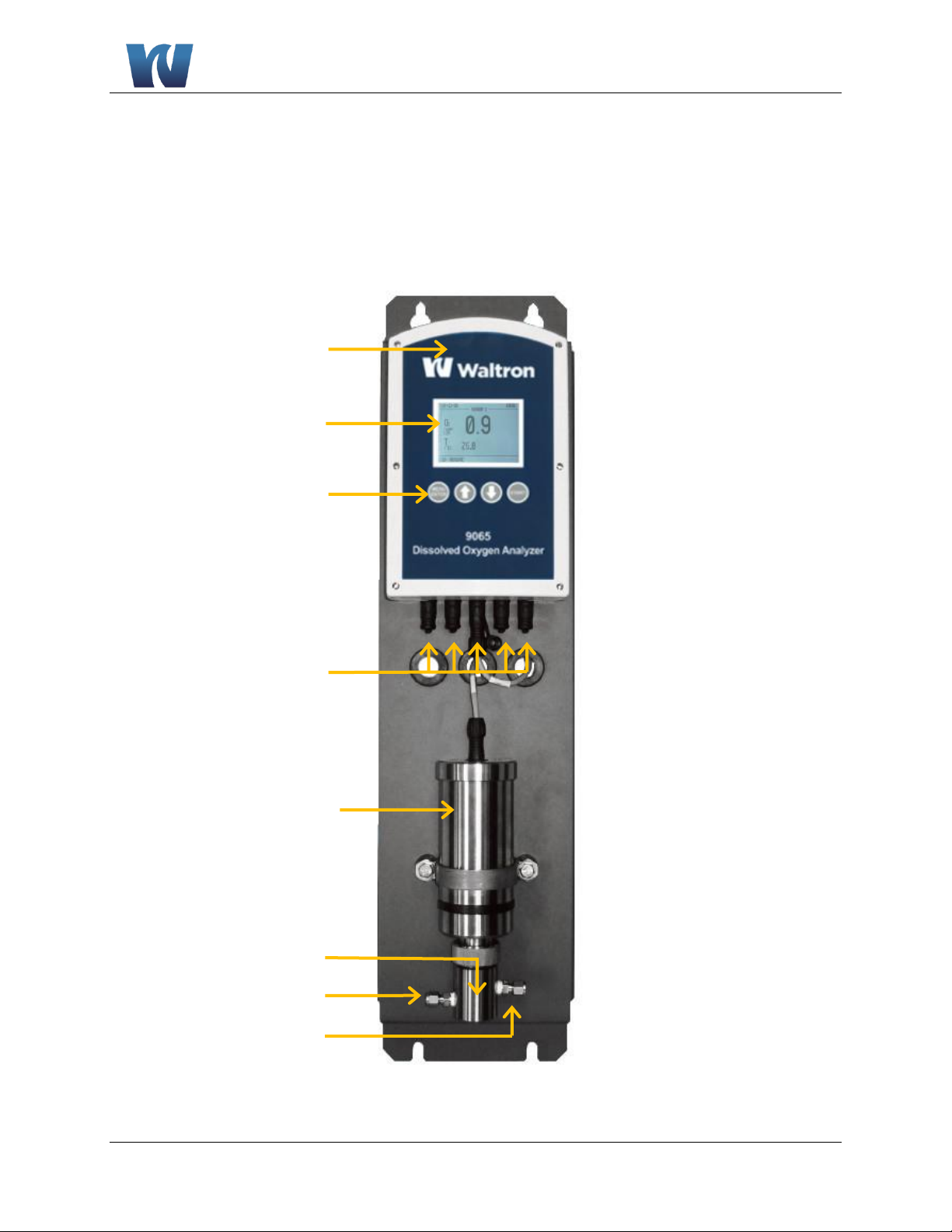
Transmitter
Display
User Interface
Transmitter
Connections
Sensor Housing
Flowcell
Sample Inlet
Sample Outlet
2 INTRODUCTION
2.1 ANALYZER OVERVIEW
The 9065 has two main sections:
1. Transmitter
2. Sensor Housing
Figure 2.1: Analyzer overview.
Introduction
13
Waltron User Manual
9065 Luminescent Dissolved Oxygen Analyzer
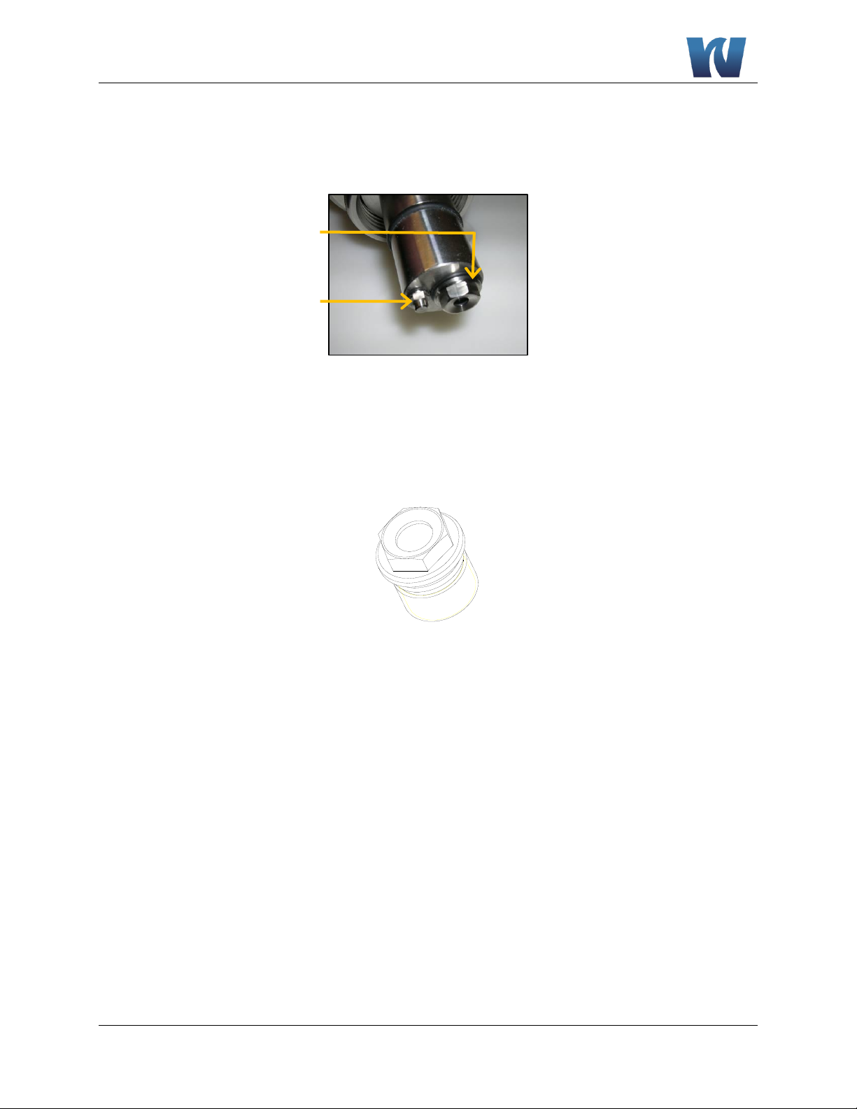
Coatingholder
Temperature
2.2 SENSOR
The bottom of the sensor housing provides the location of the dissolved oxygen sensor, shown in
the figure below.
Figure 2.2: 25 mm Sensor.
2.3 COATINGHOLDER
2.4 O
The 9065 coatingholder is recognizable by its hexagonal shape.
Figure 2.3: 9065 Coatingholder.
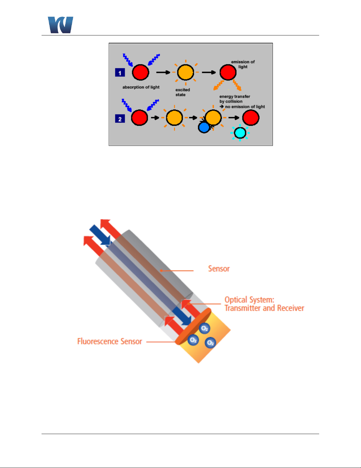
MEASUREMENT PRINCIPLE
2
The O2 measurement is based on measuring the luminescence of a layer that is sensitive to
oxygen. The luminescence changes according to the partial oxygen pressure. The quantity of
dissolved oxygen gas in the liquid is calculated with the aid of the measured partial oxygen
pressure and the temperature.
The oxygen sensor optically measures the liquid’s O
content based on the luminescence
2
measurement principle, where an oxygen-sensitive layer is exposed to blue light. As a result,
molecules in the oxygen-sensitive layer are excited.
In the absence of oxygen, the molecules light up red. In the presence of oxygen, the oxygen
molecules collide with the molecules in the oxygen-sensitive layer. The molecules that collide
with oxygen no longer light up. Through this process, a link is created between the oxygen
concentration and both the light intensity and the speed at which the light intensity is reduced.
The light intensity reduces when the oxygen concentration is higher, whilst the light intensity
reduces at a faster speed.
Introduction
14
Waltron User Manual
9065 Luminescent Dissolved Oxygen Analyzer
Figure 2.4: Luminescence in the absence of oxygen (1) and in the presence of oxygen (2).
The oxygen content is calculated using the time difference between the exposure to the blue light
and the molecules lighting up (phase shift) and the product temperature. The sensor in the 9065 is
located behind the inlet and before the throttle.
Figure 2.5: Optical sensor depiction.

Installation
15
Waltron User Manual
9065 Luminescent Dissolved Oxygen Analyzer
NOTE:
Before using the instrument, you must make sure the
instrument is complete and no parts are missing.
Make sure the 9065 is not connected to a sampling point
that produces pressures or pressure peaks greater than 10
bar.
3 INSTALLATION
3.1 CONTENT OF THE DELIVERY
The 9065 is calibrated, checked and tested by Waltron before shipment and the instrument is,
therefore, ready for immediate use. It is not necessary to calibrate the instrument again before it is
used for the first time.
Check whether the delivery is complete and undamaged. If the delivery is incomplete or
damaged, contact Waltron or the Waltron representative in your region immediately (see
www.waltron.net). Always state the serial number, the order number or the invoice number (as
given by Waltron) of the 9065 in all correspondence.
The delivery includes:
Transmitter
Sensor
Mounting plate
Power cable
Sensor communication cable
I/O cable for the analog outputs
Instruction manual
RS-232 Cable
Optional extras that can be ordered:
CD-rom with PC software for reading data incl. RS-232 Cable.
Sensor houseing mounting bracket
See Appendix C for a complete list of spare parts and components.
3.2 PRE-INSTALLATION
 Loading...