

Page 1
Rev. 1.2
Assembly Instructions – Dosing Valves WDV-0x
Page 1 of 34
Walther Systemtechnik GmbH – D 76726 Germersheim
Telefon: +49 (0)7274-7022-0 Telefax: +49 (0)7274-7022-91
http://www.walther-2000.de – info@walther-2000.de
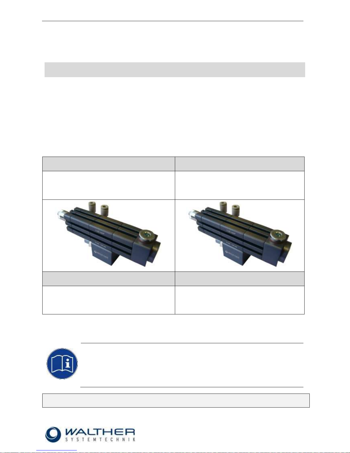
Assembly Instructions
Dosing Valves
Article Numbers: WDV-01 Dosing volume 0.001 – 0.020 cm³
WDV-02 Dosing volume 0.010 – 0.200 cm³
WDV-03 Dosing volume 0.100 – 2.000 cm³
WDV-04 Dosing volume 1.000 – 6.000 cm³
WDV-01
WDV-02
WALTHER-Dosing Valve
0.001 – 0.020 cm³
(1 – 20 mm³)
WALTHER-Dosing Valve
0.010 – 0.200 cm³
(10 – 200 mm³)
WDV-03
WDV-04
WALTHER-Dosing Valve
0.100 – 2.000 cm³
(100 – 2000 mm³)
WALTHER-Dosing Valve
1.000 – 6.000 cm³
(1000 – 6000 mm³)
NOTE
Please read these Assembly Instructions carefully before first using the device and strictly
adhere to the instructions!
This device may only be worked with and worked on by persons who are familiar with the
Assembly Instructions and the current regulations for industrial safety and accident
prevention.
Always keep this translation of the “Original Assembly Instructions“ at the device!
The manual has to be available anytime!
Page 2

Rev. 1.2
Assembly Instructions – Dosing Valves WDV-0x
Page 2 of 34
Walther Systemtechnik GmbH – D 76726 Germersheim
Telefon: +49 (0)7274-7022-0 Telefax: +49 (0)7274-7022-91
http://www.walther-2000.de – info@walther-2000.de
Table of Contents
Page
EC DECLARATION OF INCORPORATION ....................................................................................................................... 4
1 INTRODUCTION ................................................................................................................................................. 5
1.1 TARGET GROUP OF THE ASSEMBLY INSTRUCTIONS ............................................................................................................ 5
1.2 LIST OF SIGNS AND SYMBOLS ....................................................................................................................................... 5
2 SAFETY............................................................................................................................................................... 5
2.1 GENERAL INFORMATION ............................................................................................................................................. 5
2.2 DANGERS FROM RESIDUAL ENERGIES ............................................................................................................................. 5
2.3 WARRANTY AND LIABILITY ........................................................................................................................................... 5
2.4 CORRECT USE ........................................................................................................................................................... 6
2.5 INCORRECT USE ........................................................................................................................................................ 6
2.6 QUALIFICATION OF PERSONNEL .................................................................................................................................... 6
3 TRANSPORT ....................................................................................................................................................... 7
3.1 PACKAGING .............................................................................................................................................................. 7
3.2 TASKS BEFORE TRANSPORT .......................................................................................................................................... 7
4 DESCRIPTION OF FUNCTION .............................................................................................................................. 7
4.1 DESIGNATED USE OF THE INCOMPLETE DEVICE ................................................................................................................ 7
4.2 TYPE LABEL OF THE INCOMPLETE DEVICE ........................................................................................................................ 7
4.3 FUNCTIONAL PRINCIPLE .............................................................................................................................................. 8
4.4 STEPS IN THE DOSING PROCESS WITH THE WDV .............................................................................................................. 9
4.5 TECHNICAL DATA ..................................................................................................................................................... 11
5 INITIAL START-UP ............................................................................................................................................. 12
5.1 MOUNTING AND INSTALLATION .................................................................................................................................. 12
5.2 ADJUSTING THE INCOMPLETE DEVICE .......................................................................................................................... 12
6 OPERATION ..................................................................................................................................................... 13
6.1 GENERAL INFORMATION ........................................................................................................................................... 13
6.2 OPERATING ELEMENTS ............................................................................................................................................. 13
6.3 ADJUSTING THE DOSED QUANTITY .............................................................................................................................. 13
7 TAKING OUT OF SERVICE ................................................................................................................................. 14
7.1 SHORT INTERRUPTION .............................................................................................................................................. 14
7.2 LONG-TERM INTERRUPTION ....................................................................................................................................... 14
7.3 SHUTDOWN OF DEVICE ............................................................................................................................................. 14
8 MAINTENANCE AND REPAIR ............................................................................................................................ 15
8.1 GENERAL INFORMATION ........................................................................................................................................... 15
8.2 ROUTINE TASKS ....................................................................................................................................................... 15
8.3 CLEANING .............................................................................................................................................................. 15
8.4 SPARE PARTS .......................................................................................................................................................... 15
8.5 CUSTOMER SERVICE / SUPPORT .................................................................................................................................. 16
9 TROUBLESHOOTING ........................................................................................................................................ 16
9.1 GENERAL INFORMATION ........................................................................................................................................... 16
10 APPENDIX ........................................................................................................................................................ 17
10.1 DIMENSIONED DRAWING – DOSING VALVE WDV-01 ................................................................................................ 17
10.1.1 Spare Part Drawing – Dosing Valve WDV-01 ........................................................................................ 18
10.1.2 Spare Part List Dosing Valve WDV-01 up to batch no. 013078 ............................................................. 19
10.1.3 Spare Part List Dosing Valve WDV-01 from batch no. 018633 .............................................................. 20
10.1.4 Wear Part Kits ...................................................................................................................................... 20
10.2 DIMENSIONED DRAWING DOSING VALVE WDV-02 ................................................................................................... 21
10.2.1 Spare Part Drawing Dosing Valve WDV-02 ........................................................................................... 22
Page 3

Rev. 1.2
Assembly Instructions – Dosing Valves WDV-0x
Page 3 of 34
Walther Systemtechnik GmbH – D 76726 Germersheim
Telefon: +49 (0)7274-7022-0 Telefax: +49 (0)7274-7022-91
http://www.walther-2000.de – info@walther-2000.de
10.2.2 Spare Part List Dosing Valve WDV-02 up to batch no. 014696 ............................................................. 23
10.2.3 Spare Part List Dosing Valve WDV-02 from batch no. 018322 ............................................................. 24
10.2.4 Wear Part Kits ...................................................................................................................................... 24
10.3 DIMENSIONED DRAWING DOSING VALVE WDV-03 ................................................................................................... 25
10.3.1 Spare Part Drawing Dosing Valve WDV-03 ........................................................................................... 26
10.3.2 Spare Part List Dosing Valve WDV-03 up to batch no. 011386 ............................................................ 27
10.3.3 Spare Part List Dosing Valve WDV-03 from batch no. 016056 ............................................................. 28
10.3.4 Wear Part Kits ...................................................................................................................................... 28
10.4 DIMENSIONED DRAWING DOSING VALVE WDV-04 ................................................................................................... 29
10.4.1 Spart Part Drawing Dosing Valve WDV-04 ........................................................................................... 30
10.4.2 Spare Part List Dosing Valve WDV-04 up to batch no. 011387 ............................................................ 31
10.4.3 Spare Part List Dosing Valve WDV-04 from batch no. 023000 ............................................................. 32
10.4.4 Wear Part Kits ...................................................................................................................................... 32
10.5 ACCESSORIES ..................................................................................................................................................... 33
10.5.1 Data Sheet – Dosing Piston Sensor (Article No. WDV-DS) .................................................................... 34
Page 4

Rev. 1.2
Assembly Instructions – Dosing Valves WDV-0x
Page 4 of 34
Walther Systemtechnik GmbH – D 76726 Germersheim
Telefon: +49 (0)7274-7022-0 Telefax: +49 (0)7274-7022-91
http://www.walther-2000.de – info@walther-2000.de
EC Declaration of Incorporation
in accordance with EU Machinery Directive 2006/42/EU, dated 17 May 2006, Appendix II B
We herewith confirm that the below mentioned incomplete device meets the basic requirements for safety
and health as stated in EU Machinery Directive 2006/42/EU for its design and construction as well as for the
configuration released by us on the market. This machine component will not be operated before it has been
determined that the incomplete system where the machine component will be installed also meets the
requirements of the Directive (2006/42/EG).
Manufacturer
Walther Systemtechnik GmbH
Hockenheimer Straße 3
D- 76726 Germersheim
Description
Dosing Valves, Article No. WDV-01 bis 04
We also declare the conformity with other, product-relevant directives/guidelines:
Mach. Direct. 2006/42/EU App. I, Clause: 1.1.2, 1.1.3, 1.1.5, 1.1.6, 1.3.2, 1.3.3,
1.3.4, 1.5.9
EMC- Directive 2014/30/EU, dated 26. February 2014
Applied harmonized standards, in particular:
DIN EN ISO 12100 Safety of Machinery – General Design Principles –
Risk Assessment and Risk Reduction (ISO
12100:2010)
In addition, we also confirm that the special documentation according to Appendix VII Part B has
been prepared.
The manufacturer, respectively his authorized representative obligates himself to submit this documentation
to the market surveillance authorities, if requested.
This EC Declaration of Incorporation becomes invalid if the incomplete device will be altered or changed
without consent of Walther Systemtechnik GmbH.
Authorized representative for Technical Documentation:
Stefan Hirl, Hockenheimer Straße 3, D- 76726 Germersheim
Germersheim, 09 August 2016
(Place, Date) (Stefan Hirl, Management)
Page 5
Rev. 1.2
Assembly Instructions – Dosing Valves WDV-0x
Page 5 of 34
Walther Systemtechnik GmbH – D 76726 Germersheim
Telefon: +49 (0)7274-7022-0 Telefax: +49 (0)7274-7022-91
http://www.walther-2000.de – info@walther-2000.de
1 Introduction
1.1 Target Group of the Assembly Instructions
Operating Personnel
Maintenance Personnel
1.2 List of Signs and Symbols
Symbols are used to identify hazards and certain practices. Symbols are also used in the assembly
instructions. The below symbols for hazards and information describe circumstances which can result in
damages to persons, objects and environment if not observed.
The following terms and symbols are used in the assembly instructions to identify hazards:
DANGER
Describes a potentially dangerous situation.
Death, grievous bodily harm or severe material damage WILL occur if the respective
measures of precaution have not been taken.
WARNING
Describes a potentially dangerous situation.
Death, grievous bodily harm or severe material damage MAY occur if the respective
measures of precaution have not been taken.
CAUTION
Describes a potentially dangerous situation.
Slight injuries CAN occur if the respective measures of precaution have not been taken.
This signal word is also used to describe possible property damages.
IMPORTANT
Indicates tips for usage and other particularly useful information.
No dangerous situation.
2 Safety
2.1 General Information
The construction of this incomplete device is according to the latest technology and is absolutely reliable.
The individual components as well as the complete device are continuously checked by our quality management.
2.2 Dangers from Residual Energies
Please instruct the operating personnel on the respective measures to be taken against the occurrence of
mechanical, hydraulic, pneumatic and electric / electronic residual energies.
2.3 Warranty and Liability
According to the conditions laid down by the German Engineering Federation (VDMA), Walther Systemtechnik GmbH has a guarantee of 12 months under normal European operating conditions on its own parts
(spare parts are excluded); or according to the conditions of the manufacturer.
This guarantee can only be granted by Walther Systemtechnik GmbH, if:
the user has thorough knowledge of the content of these assembly instructions;
the user follows the instructions and notes contained in these assembly instructions;
the user does not rebuild or make changes on parts of the (incomplete) device without prior consent
of WST Systemtechnik GmbH.
Page 6
Rev. 1.2
Assembly Instructions – Dosing Valves WDV-0x
Page 6 of 34
Walther Systemtechnik GmbH – D 76726 Germersheim
Telefon: +49 (0)7274-7022-0 Telefax: +49 (0)7274-7022-91
http://www.walther-2000.de – info@walther-2000.de
2.4 Correct Use
CAUTION
This device will not be operated under other than the described conditions.
It has solely been designed for the dosing of media in accordance with the detailed
information of this operating manual. Any other type of use or beyond is considered as
not intended. The manufacturer cannot be made liable for damages resulting from such
incorrect use
Correct use of the device also includes:
Observing and adhering to all operating instruction s stated in this manual.
Adherence to inspection and maintenance tasks.
2.5 Incorrect Use
The manufacturer cannot be made liable for damages resulting from such incorrect use; incorrect use
includes among others:
Processing aggressive media (such as acids, alkaline, cleaning agents, chemicals etc.) or media
which have not been approved in writing by the manufacturer;
Using corrosive and / or curable materials;
Operating the device with insufficient knowledge about the operation, maintenance and care of the
device.
Making changes, extensions or alterations on the device that may hamper its safety without the prior
consent of Walther Systemtechnik GmbH.
Operating the device with defective safety installations or not properly attached or malfunctioning
safety devices.
Handling the device while energized
2.6 Qualification of Personnel
Only trained and instructed personnel may conduct work on the equipment.
The responsibilities of the personnel for assembly work, operation, repair work or maintenance work must be
clearly assigned to individuals!
Persons in training may work with the equipment only under supervision of an experienced person.
Personnel
Task
Instructed
Personnel
Personnel with Technical
Qualification
Specialist
Supervisor
Packaging, Transport
X
-
-
-
Commissioning
X
X
-
Operation
X
-
Troubleshooting, general
X
X
-
Troubleshooting
mechanical
-
X
-
-
Troubleshooting electrical
-
-
X
-
Setting up
-
X
-
-
Maintenance
-
X
-
-
Repair
-
X
X
-
Taking out of service,
Storage
-
X
X
-
Page 7
Rev. 1.2
Assembly Instructions – Dosing Valves WDV-0x
Page 7 of 34
Walther Systemtechnik GmbH – D 76726 Germersheim
Telefon: +49 (0)7274-7022-0 Telefax: +49 (0)7274-7022-91
http://www.walther-2000.de – info@walther-2000.de
3 Transport
3.1 Packaging
The type of packaging depends on the individual mode of shipping. If not separately contracted, the
packaging is in accordance with the rules and regulations of Walther Systemtechnik GmbH. This rule is in
accordance with the Federal Association for Packaging HPE.
3.2 Tasks before Transport
The following has to be done before transport:
Disconnect all power lines.
The actual transport of the device and its individual parts requires special care in order to prevent damages
from external forceful impact or careless on- and off-loading. Depending on the mode of transportation,
suitable transport and load securing has to be selected. The device will be aligned and leveled by
appropriate fastening elements.
4 Description of Function
4.1 Designated Use of the Incomplete Device
Dosing valves are used for the application of a pre-defined quantity of medium on certain selected parts. A
special drive technology (pneumatic/electric) will define and control the application time. The Dosing Valves
are also suitable for use with oil.
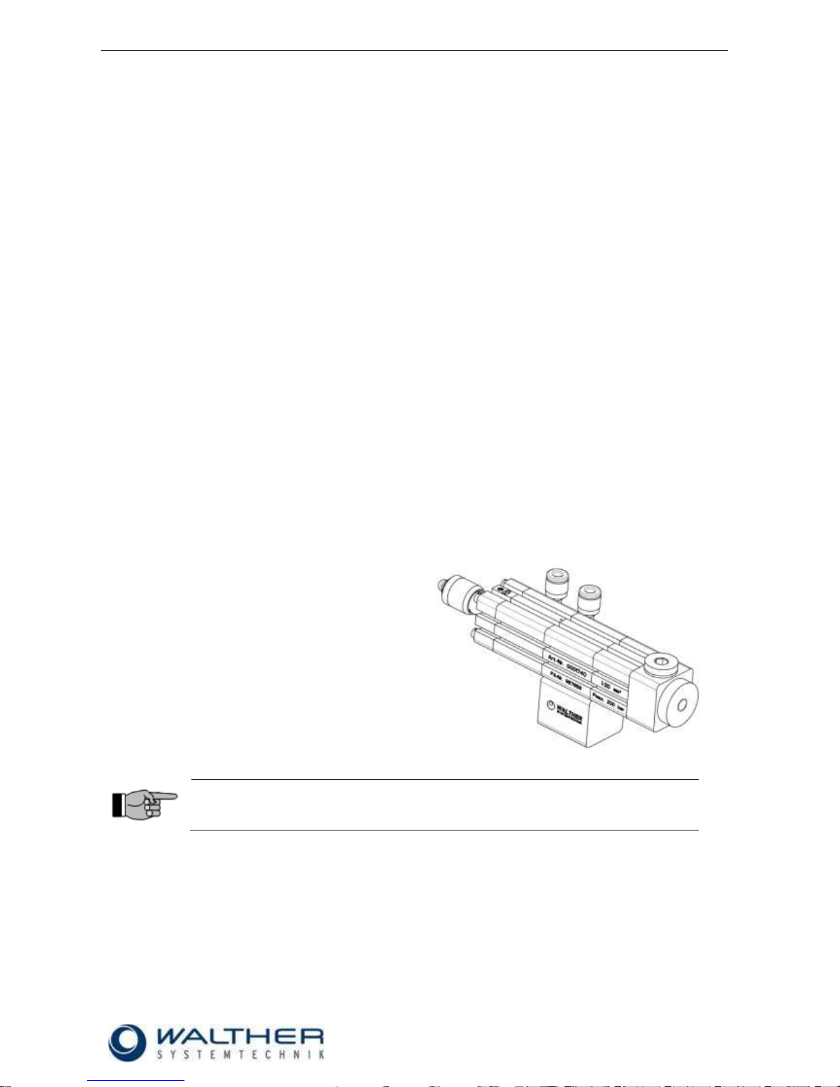
4.2 Type Label of the Incomplete Device
The Dosing Valve is marked on the side of the
housing by an engraving that contains the
production number, the article number, the max.
operating pressure and the dosing volume.
IMPORTANT
Please indicate the product information shown on the type label when ordering spare
parts or requesting technical support.
Page 8
Rev. 1.2
Assembly Instructions – Dosing Valves WDV-0x
Page 8 of 34
Walther Systemtechnik GmbH – D 76726 Germersheim
Telefon: +49 (0)7274-7022-0 Telefax: +49 (0)7274-7022-91
http://www.walther-2000.de – info@walther-2000.de
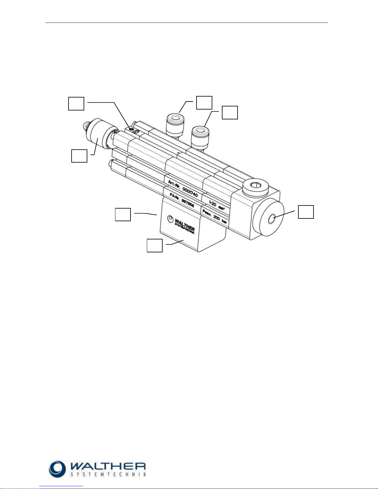
4.3 Functional Principle
The pneumatic part of the dosing valve is controlled by a 5/2-way valve. This initiates the grease dosing. The
dosing pressure depends on the lubricant feed pressure (medium).
In order to obtain a high quality and repeatability of the dosing process, the complete cycle must be completed. This means that the control piston must be driven from the starting position to the dosing position and
then back to the starting position.
LEGEND
Pos. Description
1 Support bracket
2 Connection for medium G 1/8“ (in the back of the support frame)
3 Connection for air ø4 mm
4 Regulating screw
5 Dosing output
6 Fastening screw
5 3 3 4 1
2
6
Page 9
Rev. 1.2
Assembly Instructions – Dosing Valves WDV-0x
Page 9 of 34
Walther Systemtechnik GmbH – D 76726 Germersheim
Telefon: +49 (0)7274-7022-0 Telefax: +49 (0)7274-7022-91
http://www.walther-2000.de – info@walther-2000.de
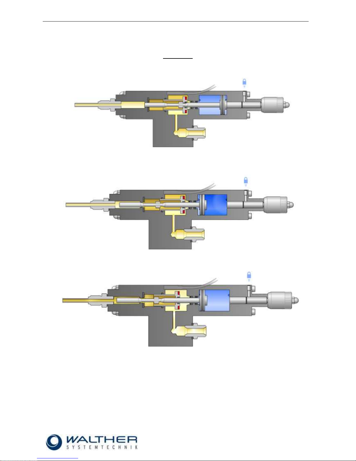
4.4 Steps in the Dosing Process with the WDV
I Dosing lift
1. The dosing chamber is filled with medium before the actual dosing
Controlled via an external 5/2-way valve, the air piston first moves to the front end position
2. After having reached the end position, the dosing piston moves and the dosing chamber is emptied
Page 10
Rev. 1.2
Assembly Instructions – Dosing Valves WDV-0x
Page 10 of 34
Walther Systemtechnik GmbH – D 76726 Germersheim
Telefon: +49 (0)7274-7022-0 Telefax: +49 (0)7274-7022-91
http://www.walther-2000.de – info@walther-2000.de
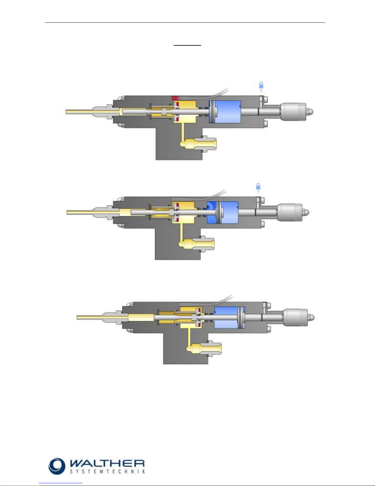
II Refill lift
3. Once the dosing piston reaches the end position, the dosing piston sensor sends a signal, if
applicable. The volume has been completely dosed.
4. Controlled by the external 5/2-way valve, the air piston is moved back into the basic position.
5. Also the dosing piston will be moved hereby and the dosing chamber is refilled by in-flowing medium.
Both pistons have returned into the basic position.
6. The cycle can start again.
Page 11
Rev. 1.2
Assembly Instructions – Dosing Valves WDV-0x
Page 11 of 34
Walther Systemtechnik GmbH – D 76726 Germersheim
Telefon: +49 (0)7274-7022-0 Telefax: +49 (0)7274-7022-91
http://www.walther-2000.de – info@walther-2000.de
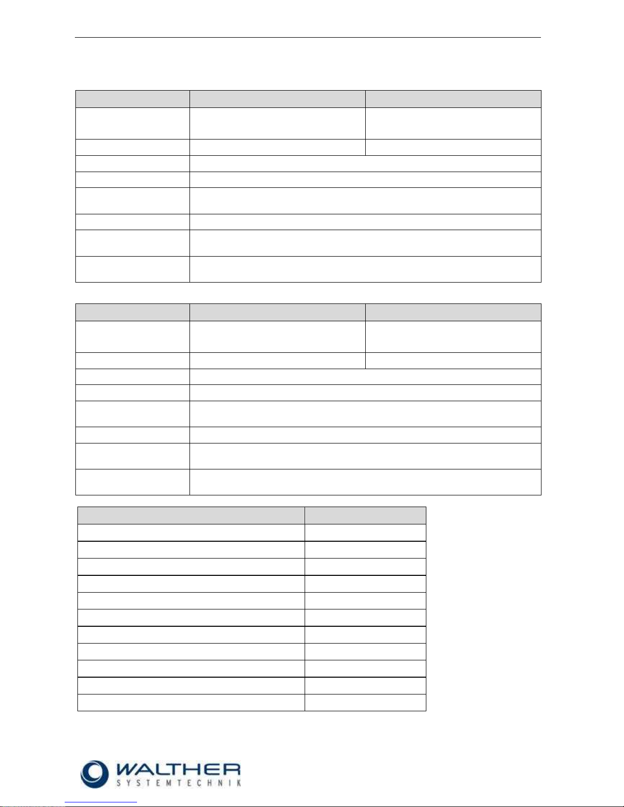
4.5 Technical Data
WALTHER-Dosing Valve WDV-01
WALTHER-Dosing Valve WDV-02
Dosing range [cm³] / [mm³]
0.001 – 0.020
1 – 20
0.010 – 0.200
10 – 200
Weight [kg]
0.180
0.182
Material inlet [mm]
External thread G 1/8
Material outlet [mm]
Internal thread M61
Compressed air supply
[mm]
Swivel-type angles M 3 for hose 4/2
Fixture [mm]
2 x M 4
min. / max. material inlet
pressure [bar]
20 / 200
min. / max. pneumatic
operating pressure [bar]
5 / 7
1
Do not exceed the max. screw-in depth!
WALTHER-Dosing Valve WDV-03
WALTHER-Dosing Valve WDV-04
Dosing range [cm³] / [mm³]
0.100 – 2.000
100 – 2000
1.000 – 6.000
1000 – 6000
Weight [kg]
0.773
0.802
Material inlet [mm]
External thread G 1/4
Material outlet [mm]
Internal thread G 1/8
Compressed air supply
[mm]
Swivel-type angles M 3 for hose 4/2
Fixture [mm]
2 x M 4
min. / max. material inlet
pressure [bar]
20 / 160
min. / max. pneumatic
operating pressure [bar]
5 / 7
Article Number
WDV-DS
Construction type
2.9 x 16.8 x 4.5
Switching output
PNP
Switching function
NO switch
Electrical version
DC voltage
Rated operating voltage [V DC]
24
Rated normal current [mA]
100
Ambient temperature min. [C°]
-25
Ambient temperature max. [C°]
+85
Connection
cable with plug connector
Protection type according to DIN 40050
IP 67
Housing material
PA 12
Page 12

Rev. 1.2
Assembly Instructions – Dosing Valves WDV-0x
Page 12 of 34
Walther Systemtechnik GmbH – D 76726 Germersheim
Telefon: +49 (0)7274-7022-0 Telefax: +49 (0)7274-7022-91
http://www.walther-2000.de – info@walther-2000.de
5 Initial Start-up
5.1 Mounting and Installation
IMPORTANT
We recommend adding a maintenance unit to the control air.
5.2 Adjusting the Incomplete Device
IMPORTANT
In order to ensure optimal operation of the valves, make sure that the air supply
pressure is set to approx. 6 bar.
The lubricant feed pressure should not exceed 200 bar at the input. To ensure this,
check the pressure conversion ratio of the lubricant feed pump. The feed pressure may
be reduced by means of an air pressure control valve (The use of an air pressure
control valve may be advantageous, although it is not imperative as long as the 200
bar are not exceeded).
IMPORTANT
All dosing valves are tested by the manufacturer prior to shipping. Due to testing, residues of test liquid may be found inside the valve.
1) Make sure that the lubricant feed hose is filled with lubricant and all air is removed. Then connect
feed hose and air connectors according to drawing.
2) For first operation, set valve to maximum dosage (i.e. turn adjustment screw to outmost position).
3) If the adjustment screw cannot be turned, change position of change-over-valve. The adjustment
screw should now be unlocked.
4) Execute a first shot of lubricant. Then set the adjustment screw to the desired grease quantity.
5) Keep the distance from the metering valve to the greasing point short. This allows for improved
metering precision and repeatability.
6) The minimum cycle time depends on the viscosity of the lubricant, as well as on the lubricant feed
pressure.
7) The dosing valves with support bracket can be fastened with four M5 screws.
8) The dosing amount can be adjusted via the dosing screw.
9) When installing the (optional) dosing sensors, please consider that there are 2 switching points per
magnetic field.
5/2-way valve
Page 13

Rev. 1.2
Assembly Instructions – Dosing Valves WDV-0x
Page 13 of 34
Walther Systemtechnik GmbH – D 76726 Germersheim
Telefon: +49 (0)7274-7022-0 Telefax: +49 (0)7274-7022-91
http://www.walther-2000.de – info@walther-2000.de
6 Operation
6.1 General Information
This incomplete device may only be operated if the safety-related equipment is permanently effective and
not suspended during operation or altered in its intended effectiveness.
6.2 Operating Elements
6.3 Adjusting the Dosed Quantity
Loosen fastening screw.
Activate and hold external way-valve or dosing trigger.
Use regulating screw to adjust the desired volume/quantity.
Let the dosing trigger go.
Tighten fastening screw.
Regulating
screw
Fastening
screw
Page 14

Rev. 1.2
Assembly Instructions – Dosing Valves WDV-0x
Page 14 of 34
Walther Systemtechnik GmbH – D 76726 Germersheim
Telefon: +49 (0)7274-7022-0 Telefax: +49 (0)7274-7022-91
http://www.walther-2000.de – info@walther-2000.de
7 Taking out of Service
7.1 Short Interruption
A short interruption (15 min or more) has to be followed by a fine dosing
IMPORTANT
Please follow the maintenance instructions!
7.2 Long-term Interruption
The following has to be observed for a long-term interruption of the device:
Make sure that system is depressurized (check all displays).
IMPORTANT
Please follow the maintenance instructions!
7.3 Shutdown of Device
Please observe the following for a shutdown of the device:
Disconnect mains plug.
Depressurize complete systems (check all displays).
Grease / oil have to be disposed of properly.
Clean dosing valve with special thinner
CAUTION
Danger of accidents and to environment. Do not spill grease / oil. Grease / oil have to
be properly disposed of (hazardous material).
IMPORTANT
Please follow the maintenance instructions!
Page 15

Rev. 1.2
Assembly Instructions – Dosing Valves WDV-0x
Page 15 of 34
Walther Systemtechnik GmbH – D 76726 Germersheim
Telefon: +49 (0)7274-7022-0 Telefax: +49 (0)7274-7022-91
http://www.walther-2000.de – info@walther-2000.de
8 Maintenance and Repair
8.1 General Information
CAUTION
Before starting any maintenance or repair work, ensure that all air-operated tools are
depressurized and disconnected from the air supply.
Before opening the dosing valve it must be disconnected from the air and fluid supply.
Otherwise, ejected components can cause injuries.
IMPORTANT
This chapter does not explain how to repair damage of the device. Repair work shall be
executed exclusively by skilled and trained experts, or by staff of the manufacturer`s
customer service.
8.2 Routine Tasks
The maintenance intervals stated below are valid for single-shift operation of the equipment. In case of
multiple-shift or very intensive operation, maintenance intervals must be shortened accordingly. Also take
into account other influences on maintenance need, such as dirty environment.
WHEN
WHAT
HOW
WHO
Weekly
Check dosing valve for
leak-tightness and
damage
Visual inspection
Expert
Weekly
Check all screw
connections and
connections of
mountings for tightness
Visual inspection
Expert
Monthly
Check electrical
conducts for damage
Visual inspection
Expert
CAUTION
After maintenance tasks are completed, check all functions and safety devices.
8.3 Cleaning
IMPORTANT
Only use soft brushes for outside cleaning of the nozzle tips. Never use metal tools
with sharp edges.
8.4 Spare Parts
IMPORTANT
Only use original spare parts from the manufacturer!
Wrong or defective spare parts from other manufacturers can damage the device. If
other than original spare parts of the manufacturer will be used, all obligations from the
manufacturer or his sales partners, such as guarantees, service contracts etc will be
forfeited without further notice.
Page 16

Rev. 1.2
Assembly Instructions – Dosing Valves WDV-0x
Page 16 of 34
Walther Systemtechnik GmbH – D 76726 Germersheim
Telefon: +49 (0)7274-7022-0 Telefax: +49 (0)7274-7022-91
http://www.walther-2000.de – info@walther-2000.de
8.5 Customer Service / Support
Walther Systemtechnik GmbH
Hockenheimer Straße 3
D-76726 Germersheim
Germany
Phone ++49(0)7274-7022-0
Fax ++49(0)7274-7022-91
Email info@walther-2000.de
Internet www.walther-2000.de
9 Troubleshooting
9.1 General Information
IMPORTANT
First check all supply lines for connection and serviceability.
Only a trained technician will take care of the below described malfunctions.
In case of serious problems that cannot be resolved, please contact the Walther Systemtechnik GmbH
customer service.
Malfunction
Possible cause
Action
Valve is actuated, but
no lubricant is ejected.
Is no lubricant fed by
the feed pump?
Check feed pump.
See operating manual of feed pump.
Check venting screw of feed pump.
See operating manual of feed pump.
Leakage
Check dosing valve.
Leakage at bore hole
Seals defective
Exchange seals
Permanent signal from
sensor
Sensor defective
Exchange sensor
Dosing volume too
small
Check dosing valve; check setting of dosing
volume and increase, if necessary; check position
of sensors
Feed pressure of
grease too high
Reduce pump pressure to max. operating
pressure of dosing valve; possibly employ a
material pressure regulator
No signal from sensor
Broken cable
Exchange cable
Sensor defective
Exchange sensor
Dosing piston in starting
position
Check pump pressure; check bore hole of grease
supply for contaminants
Air pockets in grease
system.
Air pockets in grease
container.
Air pockets in tubing.
Disconnect tubing to dosing valve. Drain a quantum of grease. Restart with dosage adjustment
screw set to maximum.
Page 17

Rev. 1.2
Assembly Instructions – Dosing Valves WDV-0x
Page 17 of 34
Walther Systemtechnik GmbH – D 76726 Germersheim
Telefon: +49 (0)7274-7022-0 Telefax: +49 (0)7274-7022-91
http://www.walther-2000.de – info@walther-2000.de
10 Appendix
10.1 Dimensioned Drawing – Dosing Valve WDV-01
Page 18

Rev. 1.2
Assembly Instructions – Dosing Valves WDV-0x
Page 18 of 34
Walther Systemtechnik GmbH – D 76726 Germersheim
Telefon: +49 (0)7274-7022-0 Telefax: +49 (0)7274-7022-91
http://www.walther-2000.de – info@walther-2000.de
10.1.1 Spare Part Drawing – Dosing Valve WDV-01
Page 19

Rev. 1.2
Assembly Instructions – Dosing Valves WDV-0x
Page 19 of 34
Walther Systemtechnik GmbH – D 76726 Germersheim
Telefon: +49 (0)7274-7022-0 Telefax: +49 (0)7274-7022-91
http://www.walther-2000.de – info@walther-2000.de
10.1.2 Spare Part List Dosing Valve WDV-01 up to batch no. 013078
Pos.
Artikelnummer
Bezeichnung
Description
Menge/Qty
1
970001739
Anschlussblock
Connecting block
1
2
970001224
O-ring
O-ring
1
3
978460002
Spiral Spannstift S
Spiral pin S
1
4
970001734
Fettzylinder
Grease cylinder
1
5
978423904
Zyl. Schraube
Socket head screw
2
6
970001525
Nutenstein
Slot nut
2
7
970001735
Anschlussstück
Connecting piece
1
8
978227800
O-ring
O-ring
1
9
978223401
O-ring
O-ring
5
10
970001038
Kolben
Piston
1
11
978221401
Glydring Stange 3x2 hydr.
Glydring rog 3x2 hydr.
2
12
970001738
Luftzylinder
Air cylinder
1
13
970001737
Endstück
End piece
1
14
970001045
Anschlag
Stop
1
15
970001043
Kolben
Piston
1
16
970001039
Nadel
Needle
1
17
970001041
Hülse
Sleeve
1
18
978353502
Nutring
Slot ring
1
19
970001042
Buchse
Socket
1
20
978411400
Hutmutter
Cap nut
1
21
970001226
Zylinderschraube
Socket head screw
1
22
978221400
O-ring
O-ring
1
23
978221600
O-ring
O-ring
1
24
978220400
O-ring
O-ring
1
25
970001106
X-ring
X-ring
1
26
978225600
O-ring
O-ring
1
27
970001044
Magnet
Magnet
1
28
970001227
Stift
Pin 1 29
978510101
Gewindestift
Set screw
1
30
970001228
Schraube
Screw
4
31
978634201
Einschraubwinkel M3 – ø4
Male elbow M3 – ø4
2
32
970001733
Adapter
Adapter
1
33
978026600
Flachdichtung
Gasket
1
34
978430001
Verschlussschraube
Lock screw
1
Page 20

Rev. 1.2
Assembly Instructions – Dosing Valves WDV-0x
Page 20 of 34
Walther Systemtechnik GmbH – D 76726 Germersheim
Telefon: +49 (0)7274-7022-0 Telefax: +49 (0)7274-7022-91
http://www.walther-2000.de – info@walther-2000.de
10.1.3 Spare Part List Dosing Valve WDV-01 from batch no. 018633
Pos.
Artikelnummer
Bezeichnung
Description
Menge/Qty
1
970001739
Anschlussblock
Connecting block
1
2
970001224
O-ring
O-ring
1
3
978460002
Spiral Spannstift S
Spiral pin S
1
4
970002730
Fettzylinder
Grease cylinder
1
5
978423904
Zyl. Schraube
Socket head screw
2
6
970002213
Nutenstein
Slot nut
2
7
970002731
Anschlussstück
Connecting piece
1
8
978227800
O-ring
O-ring
1
9
978223401
O-ring
O-ring
5
10
970001038
Kolben
Piston
1
11
978221401
Glydring Stange 3x2 hydr.
Glyd-ring rod 3x2 hydr.
2
12
970002735
Luftzylinder
Air cylinder
1
13
970002733
Endstück
End piece
1
14
970001045
Anschlag
Stop
1
15
970001043
Kolben
Piston
1
16
970001039
Nadel
Needle
1
17
970001041
Hülse
Sleeve
1
18
978353502
Nutring
Slot ring
1
19
970001042
Buchse
Socket
1
20
978411400
Hutmutter
Cap nut
1
21
970001226
Zylinderschraube
Socket head screw
1
22
978221400
O-ring
O-ring
1
23
978221600
O-ring
O-ring
1
24
978220400
O-ring
O-ring
1
25
970001106
X-ring
X-ring
1
26
978225600
O-ring
O-ring
1
27
970001044
Magnet
Magnet
1
28
970001227
Stift
Pin 1 29
978510101
Gewindestift
Set screw
1
30
970001228
Schraube
Screw
4
31
970002633
Einschraubwinkel M2,5 – ø4
Male elbow M2,5 – ø4
2
32
970001733
Adapter
Adapter
1
33
978026600
Flachdichtung
Gasket
1
34
978430001
Verschlussschraube
Lock screw
1
10.1.4 Wear Part Kits
Wear parts kit complete for WDV-01
Consisting of:
# Pos. 2,8,9,22,23,24 / O-ring
# Pos. 11 / Glyd-ring
# Pos. 17 / Sleeve
# Pos. 18 / Slot ring
# Pos. 25 / X-Ring
# Pos. Gasket
Artikel-Nr.
Description
974191850
Wear part kit for WDV-01, VITON1
1 Wear part kits are compatible with batch numbers
Page 21

Rev. 1.2
Assembly Instructions – Dosing Valves WDV-0x
Page 21 of 34
Walther Systemtechnik GmbH – D 76726 Germersheim
Telefon: +49 (0)7274-7022-0 Telefax: +49 (0)7274-7022-91
http://www.walther-2000.de – info@walther-2000.de
10.2 Dimensioned Drawing Dosing Valve WDV-02
Page 22

Rev. 1.2
Assembly Instructions – Dosing Valves WDV-0x
Page 22 of 34
Walther Systemtechnik GmbH – D 76726 Germersheim
Telefon: +49 (0)7274-7022-0 Telefax: +49 (0)7274-7022-91
http://www.walther-2000.de – info@walther-2000.de
10.2.1 Spare Part Drawing Dosing Valve WDV-02
Page 23

Rev. 1.2
Assembly Instructions – Dosing Valves WDV-0x
Page 23 of 34
Walther Systemtechnik GmbH – D 76726 Germersheim
Telefon: +49 (0)7274-7022-0 Telefax: +49 (0)7274-7022-91
http://www.walther-2000.de – info@walther-2000.de
10.2.2 Spare Part List Dosing Valve WDV-02 up to batch no. 014696
Pos.
Artikelnummer
Bezeichnung
Description
Menge/Qty
1
970001739
Anschlussblock
Connecting block
1
2
970001224
O-ring
O-ring
1
3
978460002
Spiral Spannstift S
Spiral pin S
1
4
970001734
Fettzylinder
Grease cylinder
1
5
978423904
Zyl. Schraube
Socket head screw
2
6
970001525
Nutenstein
Slot nut
2
7
970001736
Anschlussstück
Connecting piece
1
8
970001628
O-ring
O-ring
1
9
978223401
O-ring
O-ring
5
10
970001629
Kolben
Piston
1
11
978221401
Glydring Stange 3x2 hydr.
Glydring rog 3x2 hydr.
2
12
970001738
Luftzylinder
Air cylinder
1
13
970001737
Endstück
End piece
1
14
970001045
Anschlag
Stop
1
15
970001043
Kolben
Piston
1
16
970001039
Nadel
Needle
1
17
970001041
Hülse
Sleeve
1
18
978353502
Nutring
Slot ring
1
19
970001042
Buchse
Socket
1
20
978411400
Hutmutter
Cap nut
1
21
970001226
Zylinderschraube
Socket head screw
1
22
978221400
O-ring
O-ring
1
23
978221600
O-ring
O-ring
1
24
978220400
O-ring
O-ring
1
25
970001106
X-ring
X-ring
1
26
978225600
O-ring
O-ring
1
27
970001044
Magnet
Magnet
1
28
970001227
Stift
Pin 1 29
978510101
Gewindestift
Set screw
1
30
970001228
Schraube
Screw
4
31
978634201
Einschraubwinkel M3 – ø4
Male elbow M3 – ø4
2
32
970001733
Adapter
Adapter
1
33
978026600
Flachdichtung
Gasket
1
34
978430001
Verschlussschraube
Lock screw
1
Page 24

Rev. 1.2
Assembly Instructions – Dosing Valves WDV-0x
Page 24 of 34
Walther Systemtechnik GmbH – D 76726 Germersheim
Telefon: +49 (0)7274-7022-0 Telefax: +49 (0)7274-7022-91
http://www.walther-2000.de – info@walther-2000.de
10.2.3 Spare Part List Dosing Valve WDV-02 from batch no. 018322
Pos.
Artikelnummer
Bezeichnung
Description
Menge/Qty
1
970001739
Anschlussblock
Connecting block
1
2
970001224
O-ring
O-ring
1
3
978460002
Spiral Spannstift S
Spiral pin S
1
4
970002730
Fettzylinder
Grease cylinder
1
5
978423904
Zyl. Schraube
Socket head screw
2
6
970002213
Nutenstein
Slot nut
2
7
970002732
Anschlussstück
Connecting piece
1
8
970001628
O-ring
O-ring
1
9
978223401
O-ring
O-ring
5
10
970001629
Kolben
Piston
1
11
978221401
Glydring Stange 3x2 hydr.
Glydring rog 3x2 hydr.
2
12
970002735
Luftzylinder
Air cylinder
1
13
970002733
Endstück
End piece
1
14
970001045
Anschlag
Stop
1
15
970001043
Kolben
Piston
1
16
970001039
Nadel
Needle
1
17
970001041
Hülse
Sleeve
1
18
978353502
Nutring
Slot ring
1
19
970001042
Buchse
Socket
1
20
978411400
Hutmutter
Cap nut
1
21
970001226
Zylinderschraube
Socket head screw
1
22
978221400
O-ring
O-ring
1
23
978221600
O-ring
O-ring
1
24
978220400
O-ring
O-ring
1
25
970001106
X-ring
X-ring
1
26
978225600
O-ring
O-ring
1
27
970001044
Magnet
Magnet
1
28
970001227
Stift
Pin 1 29
978510101
Gewindestift
Set screw
1
30
970001228
Schraube
Screw
4
31
970002633
Einschraubwinkel M2,5 – ø4
Male elbow M2,5 – ø4
2
32
970001733
Adapter
Adapter
1
33
978026600
Flachdichtung
Gasket
1
34
978430001
Verschlussschraube
Lock screw
1
10.2.4 Wear Part Kits
Wear parts kit complete for WDV-02
Consisting of:
# Pos. 2,8,9,22,23,24 / O-ring
# Pos. 11 / Glydring
# Pos. 17 / Sleeve
# Pos. 18 / Slot ring
# Pos. 25 / X-Ring
# Pos. Gasket
Artikel-Nr.
Description
974191850
Wear Part Kit for WDV-02, VITON1
1 Wear part kits are compatible with all batch numbers
Page 25

Rev. 1.2
Assembly Instructions – Dosing Valves WDV-0x
Page 25 of 34
Walther Systemtechnik GmbH – D 76726 Germersheim
Telefon: +49 (0)7274-7022-0 Telefax: +49 (0)7274-7022-91
http://www.walther-2000.de – info@walther-2000.de
10.3 Dimensioned Drawing Dosing Valve WDV-03
Page 26

Rev. 1.2
Assembly Instructions – Dosing Valves WDV-0x
Page 26 of 34
Walther Systemtechnik GmbH – D 76726 Germersheim
Telefon: +49 (0)7274-7022-0 Telefax: +49 (0)7274-7022-91
http://www.walther-2000.de – info@walther-2000.de
10.3.1 Spare Part Drawing Dosing Valve WDV-03
Page 27

Rev. 1.2
Assembly Instructions – Dosing Valves WDV-0x
Page 27 of 34
Walther Systemtechnik GmbH – D 76726 Germersheim
Telefon: +49 (0)7274-7022-0 Telefax: +49 (0)7274-7022-91
http://www.walther-2000.de – info@walther-2000.de
10.3.2 Spare Part List Dosing Valve WDV-03 up to batch no. 011386
Pos.
Artikelnummer
Bezeichnung
Description
Menge/Qty
1
970002157
Anschlussblock
Connecting block
1
2
978460002
Spiral Spannstift S
Spiral pin S
1
3
970002159
Fettzylinder
Grease cylinder
1
4
970001595
Scheibe
Washer
1
5
970002158
Anschlussstück
Connecting piece
1
6
970002161
Luftzylinder
Air cylinder
1
7
970002162
Endstück
End piece
1
8
970001582
Zwischenstück
Intermediate unit
1
9
970001584
Kolben
Piston
1
10
978331100
L-Cup_6x3.5
L-Cup_6x3.5
1
11
978365000
Stangendichtung ARUP ø6
Stepseal ARUP ø6
1
12
978223201
Glydring Stange 5.7x2 hydr.
Glydring rod 5.7x2 hydr.
2
13
970001591
Kolben
Piston
1
14
970001586
Ventilstange
Valve rod
1
15
970001590
O-Ring
O-ring
1
16
970001587
Dosierschraube
Metering screw
1
17
970001588
Regulierhülse
Metering sleeve
1
18
978424105
Zyl. Schraube
Socket head screw
1
19
978223200
O-Ring
O-ring
1
20
978411000
Hutmutter
Cap nut
1
21
970001596
Schraube
Screw
4
22
978232100
O-Ring
O-ring
4
23
970001528
Magnet
Magnet
1
24
978227302
O-Ring
O-ring
1
25
978227700
O-Ring
O-ring
1
26
978221400
O-Ring
O-ring
1
27
978222500
O-Ring
O-ring
1
28
970001589
Stift
Pin 1 29
978512700
Gewindestift
Set screw
1
30
970001525
Nutenstein
Slot nut
4
31
970001593
Zylinderschraube
Socket head screw
4
32
970002163
Anschlussstück
Connecting piece
1
33
978233000
O-Ring
O-ring
1
34
978026600
Flachdichtung
Gasket
1
35
978430001
Verschlussschraube
Lock screw
1
36
978634201
Einschraubwinkel M3 – ø4
Male elbow M3 – ø4
2
Page 28

Rev. 1.2
Assembly Instructions – Dosing Valves WDV-0x
Page 28 of 34
Walther Systemtechnik GmbH – D 76726 Germersheim
Telefon: +49 (0)7274-7022-0 Telefax: +49 (0)7274-7022-91
http://www.walther-2000.de – info@walther-2000.de
10.3.3 Spare Part List Dosing Valve WDV-03 from batch no. 016056
Pos.
Artikelnummer
Bezeichnung
Description
Menge/Qty
1
970002157
Anschlussblock
Connecting block
1
2
978460002
Spiral Spannstift S
Spiral pin S
1
3
970002746
Fettzylinder
Grease cylinder
1
4
970001595
Scheibe
Washer
1
5
970002745
Anschlussstück
Connecting piece
1
6
970002749
Luftzylinder
Air cylinder
1
7
970002750
Endstück
End piece
1
8
970001582
Zwischenstück
Intermediate unit
1
9
970001584
Kolben
Piston
1
10
978331100
L-Cup_6x3.5
L-Cup_6x3.5
1
11
978365000
Stangendichtung ARUP ø6
Stepseal ARUP ø6
1
12
978223201
Glydring Stange 5.7x2 hydr.
Glydring rod 5.7x2 hydr.
2
13
970001591
Kolben
Piston
1
14
970001586
Ventilstange
Valve rod
1
15
970001590
O-Ring
O-ring
1
16
970001587
Dosierschraube
Metering screw
1
17
970001588
Regulierhülse
Metering sleeve
1
18
978424105
Zyl. Schraube
Socket head screw
1
19
978223200
O-Ring
O-ring
1
20
978411000
Hutmutter
Cap nut
1
21
970001596
Schraube
Screw
4
22
978232100
O-Ring
O-ring
4
23
970001528
Magnet
Magnet
1
24
978227302
O-Ring
O-ring
1
25
978227700
O-Ring
O-ring
1
26
978221400
O-Ring
O-ring
1
27
978222500
O-Ring
O-ring
1
28
970001589
Stift
Pin 1 29
978512700
Gewindestift
Set screw
1
30
970002213
Nutenstein
Slot nut
4
31
970001593
Zylinderschraube
Socket head screw
4
32
970002163
Anschlussstück
Connecting piece
1
33
978233000
O-Ring
O-ring
1
34
978026600
Flachdichtung
Gasket
1
35
978430001
Verschlussschraube
Lock screw
1
36
978634201
Einschraubwinkel M3 – ø4
Male elbow M3 – ø4
2
10.3.4 Wear Part Kits
Wear parts kit complete for WDV-03
Consisting of:
# Pos.15,19,22,24,26,27 / O-ring
# Pos. 4 / Washer
# Pos. 8 / Intermediate unit
# Pos. 10 / L-Cup
# Pos. 11 / Rod seal
# Pos. 12 / Glydring
# Pos. Gasket
Artikel-Nr.
Description
970001746
Wear Part Kit for WDV-03, VITON1
1 Wear part kits are compatible with all batch numbers
Page 29

Rev. 1.2
Assembly Instructions – Dosing Valves WDV-0x
Page 29 of 34
Walther Systemtechnik GmbH – D 76726 Germersheim
Telefon: +49 (0)7274-7022-0 Telefax: +49 (0)7274-7022-91
http://www.walther-2000.de – info@walther-2000.de
10.4 Dimensioned Drawing Dosing Valve WDV-04
Page 30

Rev. 1.2
Assembly Instructions – Dosing Valves WDV-0x
Page 30 of 34
Walther Systemtechnik GmbH – D 76726 Germersheim
Telefon: +49 (0)7274-7022-0 Telefax: +49 (0)7274-7022-91
http://www.walther-2000.de – info@walther-2000.de
10.4.1 Spare Part Drawing Dosing Valve WDV-04
Page 31

Rev. 1.2
Assembly Instructions – Dosing Valves WDV-0x
Page 31 of 34
Walther Systemtechnik GmbH – D 76726 Germersheim
Telefon: +49 (0)7274-7022-0 Telefax: +49 (0)7274-7022-91
http://www.walther-2000.de – info@walther-2000.de
10.4.2 Spare Part List Dosing Valve WDV-04 up to batch no. 011387
Pos.
Artikelnummer
Bezeichnung
Description
Menge/Qty
1
970002157
Anschlussblock
Connecting block
1
2
978460002
Spiral Spannstift S
Spiral pin S
1
3
970002160
Fettzylinder
Grease cylinder
1
4
970001595
Scheibe
Washer
1
5
970002158
Anschlussstück
Connecting piece
1
6
970002161
Luftzylinder
Air cylinder
1
7
970002162
Endstück
End piece
1
8
970001582
Zwischenstück
Intermediate unit
1
9
970001583
Kolben
Piston
1
10
978331100
L-Cup_6x3.5
L-Cup_6x3.5
1
11
978365000
Stangendichtung ARUP ø6
Stepseal ARUP ø6
1
12
978223201
Glydring Stange 5.7x2 hydr.
Glydring rod 5.7x2 hydr.
2
13
970001591
Kolben
Piston
1
14
970001586
Ventilstange
Valve rod
1
15
970001590
O-Ring
O-ring
1
16
970001587
Dosierschraube
Metering screw
1
17
970001588
Regulierhülse
Metering sleeve
1
18
978424105
Zyl. Schraube
Socket head screw
1
19
978223200
O-Ring
O-ring
1
20
978411000
Hutmutter
Cap nut
1
21
970001596
Schraube
Screw
4
22
978232100
O-Ring
O-ring
4
23
970001528
Magnet
Magnet
1
24
978227700
O-Ring
O-ring
1
25
978221400
O-Ring
O-ring
1
26
978222500
O-Ring
O-ring
1
27
970001589
Stift
Pin 1 28
978512700
Gewindestift
Set screw
1
29
970001525
Nutenstein
Slot nut
4
30
970001593
Zylinderschraube
Socket head screw
4
31
970002163
Anschlussstück
Connecting piece
1
32
978233000
O-Ring
O-ring
1
33
978026600
Flachdichtung
Gasket
1
34
978430001
Verschlussschraube
Lock screw
1
35
978634201
Einschraubwinkel M3 – ø4
Male elbow M3 – ø4
2
Page 32

Rev. 1.2
Assembly Instructions – Dosing Valves WDV-0x
Page 32 of 34
Walther Systemtechnik GmbH – D 76726 Germersheim
Telefon: +49 (0)7274-7022-0 Telefax: +49 (0)7274-7022-91
http://www.walther-2000.de – info@walther-2000.de
10.4.3 Spare Part List Dosing Valve WDV-04 from batch no. 023000
Pos.
Artikelnummer
Bezeichnung
Description
Menge/Qty
1
970002157
Anschlussblock
Connecting block
1
2
978460002
Spiral Spannstift S
Spiral pin S
1
3
970002746
Fettzylinder
Grease cylinder
1
4
970001595
Scheibe
Washer
1
5
970002745
Anschlussstück
Connecting piece
1
6
970002749
Luftzylinder
Air cylinder
1
7
970002750
Endstück
End piece
1
8
970001582
Zwischenstück
Intermediate unit
1
9
970001583
Kolben
Piston
1
10
978331100
L-Cup_6x3.5
L-Cup_6x3.5
1
11
978365000
Stangendichtung ARUP ø6
Stepseal ARUP ø6
1
12
978223201
Glydring Stange 5.7x2 hydr.
Glydring rod 5.7x2 hydr.
2
13
970001591
Kolben
Piston
1
14
970001586
Ventilstange
Valve rod
1
15
970001590
O-Ring
O-ring
1
16
970001587
Dosierschraube
Metering screw
1
17
970001588
Regulierhülse
Metering sleeve
1
18
978424105
Zyl. Schraube
Socket head screw
1
19
978223200
O-Ring
O-ring
1
20
978411000
Hutmutter
Cap nut
1
21
970001596
Schraube
Screw
4
22
978232100
O-Ring
O-ring
4
23
970001528
Magnet
Magnet
1
24
978227700
O-Ring
O-ring
1
25
978221400
O-Ring
O-ring
1
26
978222500
O-Ring
O-ring
1
27
970001589
Stift
Pin 1 28
978512700
Gewindestift
Set screw
1
29
970002213
Nutenstein
Slot nut
4
30
970001593
Zylinderschraube
Socket head screw
4
31
970002163
Anschlussstück
Connecting piece
1
32
978233000
O-Ring
O-ring
1
33
978026600
Flachdichtung
Gasket
1
34
978430001
Verschlussschraube
Lock screw
1
35
978634201
Einschraubwinkel M3 – ø4
Male elbow M3 – ø4
2
10.4.4 Wear Part Kits
Wear parts kit complete for WDV-04
Consisting of:
# Pos.15,19,22,24,26,27 / O-ring
# Pos. 4 / Washer
# Pos. 8 / Intermediate unit
# Pos. 10 / L-Cup
# Pos. 11 / Rod seal
# Pos. 12 / Glydring
# Pos. Gasket
Artikel-Nr.
Description
970001746
Wear Part Kit for WDV-04, VITON1
1 Wear part kits are compatible with all batch numbers
Page 33

Rev. 1.2
Assembly Instructions – Dosing Valves WDV-0x
Page 33 of 34
Walther Systemtechnik GmbH – D 76726 Germersheim
Telefon: +49 (0)7274-7022-0 Telefax: +49 (0)7274-7022-91
http://www.walther-2000.de – info@walther-2000.de
10.5 Accessories
Picture
Article Number
Description
WDV-DS
Dosing piston sensor
(see also Product Catalog DOSING)
97PA21X-XX
Pressure sensor
(see also Product Catalog „Checking“)
979450-M6
Luer-Lock adapter, male, thread M6 for WDV-
01/02
979450-G1/8
Luer-Lock adapter, male, thread G1/8 for WDV-
03/04
Page 34

Rev. 1.2
Assembly Instructions – Dosing Valves WDV-0x
Page 34 of 34
Walther Systemtechnik GmbH – D 76726 Germersheim
Telefon: +49 (0)7274-7022-0 Telefax: +49 (0)7274-7022-91
http://www.walther-2000.de – info@walther-2000.de
10.5.1 Data Sheet – Dosing Piston Sensor (Article No. WDV-DS)
 Loading...