

Rev. 1.1
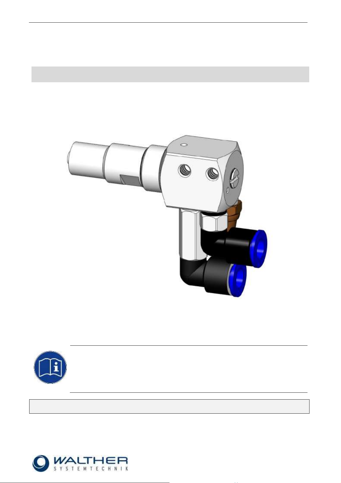
Assembly Instructions - MINI-Full-Jet Valve VMS-08
Page 1 of 16
Walther Systemtechnik GmbH – D 76726 Germersheim
Telefon: +49 (0)7274-7022-0 Telefax: +49 (0)7274-7022-91
http://www.walther-2000.de – info@walther-2000.de
NOTE
Please read the Assembly Instructions carefully before first using the incomplete device and
strictly adhere to the instructions!
This incomplete device may only be worked with and worked on by persons who are
familiar with the assembly instructions and the current regulations for industrial safety and
accident prevention.
Assembly Instructions
MINI-Full-Jet Valve VMS-08
Article Number: V08-…
Always keep a translated version of the original Assembly Instructions at the device!
The instructions have to be close at hand any time!

Rev. 1.1
Assembly Instructions - MINI-Full-Jet Valve VMS-08
Page 2 of 16
Walther Systemtechnik GmbH – D 76726 Germersheim
Telefon: +49 (0)7274-7022-0 Telefax: +49 (0)7274-7022-91
http://www.walther-2000.de – info@walther-2000.de
Table of Contents
Page
EC DECLARATION OF INCORPORATION ....................................................................................................................... 4
1 INTRODUCTION ................................................................................................................................................. 5
1.1 TARGET GROUP OF THE ASSEMBLY INSTRUCTIONS ............................................................................................................ 5
1.2 LIST OF SIGNS AND SYMBOLS ....................................................................................................................................... 5
2 SAFETY............................................................................................................................................................... 5
2.1 GENERAL INFORMATION ............................................................................................................................................. 5
2.2 DANGERS FROM RESIDUAL ENERGY ............................................................................................................................... 5
2.3 WARRANTY AND LIABILITY ........................................................................................................................................... 6
2.4 CORRECT USE ........................................................................................................................................................... 6
2.5 INCORRECT USE ........................................................................................................................................................ 6
2.6 QUALIFICATION OF PERSONNEL .................................................................................................................................... 6
3 TRANSPORT ....................................................................................................................................................... 7
3.1 PACKAGING .............................................................................................................................................................. 7
3.2 TASKS BEFORE TRANSPORT .......................................................................................................................................... 7
4 DESCRIPTION OF FUNCTION .............................................................................................................................. 7
4.1 PURPOSE OF THE INCOMPLETE DEVICE ........................................................................................................................... 7
4.2 TECHNICAL DATA ....................................................................................................................................................... 7
4.3 TYPE LABEL .............................................................................................................................................................. 7
5 INITIAL START-UP ............................................................................................................................................... 8
5.1 MOUNTING AND INSTALLATION .................................................................................................................................... 8
5.2 HOSE MOUNTING...................................................................................................................................................... 8
6 OPERATION ....................................................................................................................................................... 9
6.1 GENERAL INFORMATION ............................................................................................................................................. 9
6.2 OPERATION INSTRUCTIONS / OPERATING CONDITIONS ...................................................................................................... 9
6.3 ADJUSTING AND SETTING ............................................................................................................................................ 9
6.4 TURNING ON .......................................................................................................................................................... 10
6.5 TURNING OFF ......................................................................................................................................................... 10
7 TAKING OUT OF SERVICE ................................................................................................................................. 10
7.1 SHORT INTERRUPTION .............................................................................................................................................. 10
7.2 LONG-TERM INTERRUPTION ....................................................................................................................................... 10
7.3 SHUTDOWN OF DEVICE ............................................................................................................................................. 10
8 MAINTENANCE AND REPAIR ............................................................................................................................ 11
8.1 GENERAL INFORMATION ........................................................................................................................................... 11
8.2 CLEANING .............................................................................................................................................................. 11
8.3 ROUTINE TASKS ....................................................................................................................................................... 11
8.4 SPARE PARTS .......................................................................................................................................................... 11
8.5 REPLACING NOZZLE AND NOZZLE NEEDLE .................................................................................................................... 12
9 TROUBLESHOOTING ........................................................................................................................................ 13
9.1 GENERAL INFORMATION ........................................................................................................................................... 13
9.2 CUSTOMER SERVICE / SUPPORT .................................................................................................................................. 13
9.3 FAILURES................................................................................................................................................................ 13
10 APPENDIX ........................................................................................................................................................ 14
10.1 DIMENSIONED DRAWING ..................................................................................................................................... 14
10.2 DIMENSIONED DRAWING WITH LUER-LOCK .............................................................................................................. 14
10.3 SPARE PART DRAWING ......................................................................................................................................... 15
10.4 SPARE PART LIST ................................................................................................................................................. 15

Rev. 1.1
Assembly Instructions - MINI-Full-Jet Valve VMS-08
Page 3 of 16
Walther Systemtechnik GmbH – D 76726 Germersheim
Telefon: +49 (0)7274-7022-0 Telefax: +49 (0)7274-7022-91
http://www.walther-2000.de – info@walther-2000.de
10.5 ARTICLE NUMBERS FOR LUER-LOCK ADAPTERS ......................................................................................................... 16
10.6 ACCESSORIES ..................................................................................................................................................... 16

Rev. 1.1
Assembly Instructions - MINI-Full-Jet Valve VMS-08
Page 4 of 16
Walther Systemtechnik GmbH – D 76726 Germersheim
Telefon: +49 (0)7274-7022-0 Telefax: +49 (0)7274-7022-91
http://www.walther-2000.de – info@walther-2000.de
EC Declaration of Incorporation
in accordance with EU Machinery Directive 2006/42/EU, dated 17 May 2006, Appendix II B
We herewith confirm that the below mentioned incomplete device meets the basic requirements for
safety and health as stated in EU Machinery Directive 2006/42/EU for its design and construction
as well as for the configuration released by us on the market. This machine component will not be
operated before it has been determined that the incomplete system where the machine component
will be installed also meets the requirements of the Directive (2006/42/EG).
Manufacturer
Walther Systemtechnik GmbH
Hockenheimer Straße 3
D- 76726 Germersheim
Description
VMS-08 MINI-Full-Jet Valve, Article No. V08-…
We also declare the conformity with other, product-relevant directives/guidelines:
Mach. Direct. 2006/42/EU App. I, Clause: 1.1.2, 1.1.3, 1.1.5, 1.1.6, 1.3.2, 1.3.3,
1.3.4, 1.5.9
EMC Directive 2004/108/EU, dated 15 December 2004
Applied harmonized standards, in particular:
DIN EN ISO 12100 Safety of Machinery – General Design Principles –
Risk Assessment and Risk Reduction (ISO
12100:2010)
In addition, we also confirm that the special documentation according to Appendix VII Part B has
been prepared.
The manufacturer, respectively his authorized representative obligates himself to submit this documentation
to the market surveillance authorities, if requested.
This EC Declaration of Incorporation becomes invalid if the incomplete device will be altered or changed
without consent of Walther Systemtechnik GmbH.
Authorized representative for Technical Documentation:
Stefan Hirl, Hockenheimer Straße 3, D- 76726 Germersheim
Germersheim, 19 October 2017
(Place, Date) (Stefan Hirl, Management)
Rev. 1.1
Assembly Instructions - MINI-Full-Jet Valve VMS-08
Page 5 of 16
Walther Systemtechnik GmbH – D 76726 Germersheim
Telefon: +49 (0)7274-7022-0 Telefax: +49 (0)7274-7022-91
http://www.walther-2000.de – info@walther-2000.de
DANGER
Describes a potentially dangerous situation.
Death, grievous bodily harm or severe material damage WILL occur if the respective
measures of precaution have not been taken
WARNING
Describes a potentially dangerous situation.
Death, grievous bodily harm or severe material damage MAY occur if the respective
measures of precaution have not been taken.
CAUTION
Describes a potentially dangerous situation.
Slight injuries CAN occur if the respective measures of precaution have not been
taken. This signal word is also used to describe possible property damages.
IMPORTANT
Indicates tips for usage and other particularly useful information.
No dangerous situation.
1 Introduction
The MINI full-jet valves of the VMS-08 series are suitable for the application of oils, separating agents and
other fluid media where the liquid will be applied as dots or lines. Depending on the viscosity of the applied
medium, the application pattern can be individually adjusted via the needle stroke. Three hose are employed
for supplying control air for opening, control air for closing and medium. The full jet valves of the VMS-08
series are precision tools. Always keep clean and observe minimum instructions to maintain a long useful life
of the valve.
1.1 Target Group of the Assembly Instructions
Operating Personnel
Maintenance Personnel
1.2 List of Signs and Symbols
The assembly instructions warn users of operations which may put their health at risk.
The warnings are indicated by combinations of text and symbols as follows:
2 Safety
2.1 General Information
The construction of this incomplete device is according to the latest technology and is absolutely reliable.
The individual components as well as the complete device are continuously checked by our quality management.
2.2 Dangers from Residual Energy
Please instruct the operating personnel on the respective measures to be taken against the occurrence of
mechanical, hydraulic, pneumatic and electric / electronic residual energies.

Rev. 1.1
Assembly Instructions - MINI-Full-Jet Valve VMS-08
Page 6 of 16
Walther Systemtechnik GmbH – D 76726 Germersheim
Telefon: +49 (0)7274-7022-0 Telefax: +49 (0)7274-7022-91
http://www.walther-2000.de – info@walther-2000.de
Personnel
Task
Instructed
Personnel
Personnel with Technical
Qualification
Specialist
Supervisor
Packaging, Transport
X
-
-
-
Commissioning
X
X
-
Operation
X
-
Troubleshooting, general
X
X
-
Troubleshooting
mechanical
-
X
-
-
Troubleshooting electrical
-
-
X
-
Setting up
-
X
-
-
Maintenance
-
X
-
-
Repair
-
X
X
-
Taking out of service,
Storage
-
X
X
-
2.3 Warranty and Liability
According to the conditions laid down by the German Engineering Federation (VDMA), Walther Systemtechnik GmbH has a guarantee of 12 months under normal European operating conditions on its own parts
(spare parts are excluded); or according to the conditions of the manufacturer.
This guarantee can only be granted by Walther Systemtechnik GmbH, if:
the user has thorough knowledge of the content of the assembly instructions;
the user follows the instructions and notes contained in the assembly instructions;
the user does not rebuild or make changes on parts of the device without prior consent of WST Sys-
temtechnik GmbH.
2.4 Correct Use
The VMS-08 MINI Full-jet Valve is a needle valve suitable for the processing of sprayable media in
continuous as well as intermittent use. It is not suitable for spraying aggressive fluids such as acids, alkaline
solutions, cleaning agents, chemicals etc. In case of doubt, please contact the manufacturer.
2.5 Incorrect Use
Operating the incomplete device with insufficient knowledge about the operation, maintenance and
care of the device.
Making changes, extensions or alterations on the incomplete device that may hamper its safety
without the prior consent of Walther Systemtechnik GmbH.
Operating the incomplete device with defective safety installations or not properly attached or mal-
functioning safety devices.
Using unsuitable materials.
Handling the incomplete device while energized
2.6 Qualification of Personnel
Only trained and instructed personnel may conduct work on the equipment.
The responsibilities of the personnel for assembly work, operation, repair work or maintenance work must be
clearly assigned to individuals!
Persons in training may work with the equipment only under supervision of an experienced person.

Rev. 1.1
Assembly Instructions - MINI-Full-Jet Valve VMS-08
Page 7 of 16
Walther Systemtechnik GmbH – D 76726 Germersheim
Telefon: +49 (0)7274-7022-0 Telefax: +49 (0)7274-7022-91
http://www.walther-2000.de – info@walther-2000.de
CAUTION
The use of other media can cause functional failures, material damages or even the
complete destruction of the device.
3 Transport
3.1 Packaging
The type of packaging depends on the individual mode of shipping. If not separately contracted, the
packaging is in accordance with the rules and regulations of Walther Systemtechnik GmbH. This rule is in
accordance with the Federal Association for Packaging HPE.
3.2 Tasks before Transport
The following has to be done before transport:
Disconnect all power lines.
The actual transport of the incomplete device and its individual parts requires special care in order to prevent
damages from external forceful impact or careless on- and off-loading. Depending on the mode of
transportation, suitable transport and load securing has to be selected. The incomplete device will be aligned
and leveled by appropriate fastening elements.
4 Description of Function
4.1 Purpose of the Incomplete Device
The MINI Full-jet Valve VMS-08 is a pneumatically controlled application device for applying liquid media
such as oils or separating agents. The spraying process is generated by the control air and the material supply pressure and can be either an intermittent or continuous process.
The control air for opening will be supplied through a pilot valve (not included in scope of delivery) and will
not have a passage in the basic position. Once the pilot valve for the control air receives a signal, the front
area of the needle piston chamber will be flooded with air; this results in the needle piston pushing back
against the spring and opening the needle.
Now the material is discharged from the nozzle. If there is no signal for the pilot valve of the control air, the
needle will be pushed into the nozzle by the spring in the piston chamber and the spraying device is closed.
Needle function: opened by air pressure / closed by spring pressure.
Should the control air fail, the valve will be closed by the needle spring.
The spray medium is supplied to the valve via a pressured container or a pump.
4.2 Technical Data
Dimensions = ca. 64mm x 21mm x27mm (without nozzle)
Weight = ca. 65g
Control air pressure = 5 – 7 bar
Material pressure = max. 3 bar (without closing air)
Material pressure = max. 15 bar (with closing air)
Custom versions upon request; we reserve the right for technical changes.
4.3 Type Label
The type designation is etched in close to the material connection. The serial number is also inscribed in this
area.

Rev. 1.1
Assembly Instructions - MINI-Full-Jet Valve VMS-08
Page 8 of 16
Walther Systemtechnik GmbH – D 76726 Germersheim
Telefon: +49 (0)7274-7022-0 Telefax: +49 (0)7274-7022-91
http://www.walther-2000.de – info@walther-2000.de
CAUTION
In order to avoid malfunctions or damages on the spraying device or the system, make
sure that all pressured lines are correctly assigned and connected to the hose connections at the spraying device.
Sound absorber
Material
Control air –open-
(w/o closing air)
Important!
For use (with closing air) the
sound absorber has to be
removed and will be replaced by
an additional hose connection.
5 Initial Start-up
5.1 Mounting and Installation
The spraying device can be installed in any position.
The distance of the nozzle to the application surface depends on the required spraying width. The larger the
distance of the nozzle to the application surface, the larger will be the spraying width of the material.
Make sure that the spraying device is secured fastened on the holder or in machine!
Intermitting processes can cause vibrations.
Machine vibrations to the valves and from the valves to the machine should be avoided in order to achieve a
clean and accurate application surface.
Vibrations of the valve caused by fast intermitting cycles require solid and tight installation. Machine
vibrations to the valves should be avoided.
5.2 Hose Mounting
Control air and material will be supplied to the spraying device via two separate connections. The following
markings are used:
Control air -open- (black)
Connection S : to 3/2-way magnetic valve (without closing air)
2x to 5/2-way magnetic valve (with closing air)
Material (transparent or white)
Connection M : to pressured container or pump
Please observe prior to initial start-up:
Turn on energy supply
Turn on supply for atomizer air, control air and material
Use control unit to start device
Check correct function and proper operation of device
Check if device operation stays within all pre-set parameters
After checking that the device is properly functioning, it can be employed with due regard to the guiding
safety and accident prevention directives.

Rev. 1.1
Assembly Instructions - MINI-Full-Jet Valve VMS-08
Page 9 of 16
Walther Systemtechnik GmbH – D 76726 Germersheim
Telefon: +49 (0)7274-7022-0 Telefax: +49 (0)7274-7022-91
http://www.walther-2000.de – info@walther-2000.de
CAUTION
Never point the jet at people. The wearing of eye protection is strongly recommended.
The spraying process can create noise depending on the air and fluid pressures used.
Ear protection should be worn, if required.
WARNING
Danger caused by flammable, harmful fluid. Always follow the safety instructions on the
container or the safety data sheet for the fluid
IMPORTANT
The amount of material can be individually regulated via the regulating screw.
Right turn: decreasing material quantity
Left turn: increasing material quantity
Nozzle and needle can be damaged by wrong handling.
Only decrease the material flow (by a right turn of the regulating knob) if material is
discharged.
Do not turn the regulating knob further to the right after the nozzle is closed!
6 Operation
6.1 General Information
This device may only be operated if the safety-related equipment is permanently effective and not suspended during operation or altered in its intended effectiveness.
6.2 Operation Instructions / Operating Conditions
The valves can be controlled for intermittent or continuous use. According to the individual applica-
tion, the control air must be adjusted to the operating cycles and to the higher or lower material pressures. 40 tacts per second can be reached under appropriate operating conditions (material pressure, control air pressure, needle stroke, short conductions).
The VMS-08 usually works with a control air pressure of 5 – 7 bar.
During longer standstills the material can remain in the valve as long as it is under pressure and
does not have any contact with outside air.
Material and control air will only be used in a clean, filtered condition. Control air should be slightly
oiled when supplied to the spraying device.
The valves of the VMS-08 series usually operate with a control air pressure of 5 - 7 bar. In case high
material pressures are necessary, the safety regulations of the trade association must always be observed.
6.3 Adjusting and Setting
During longer standstills the material can remain in the valve as long as it is under pressure and does not
have any contact with outside air.

Rev. 1.1
Assembly Instructions - MINI-Full-Jet Valve VMS-08
Page 10 of 16
Walther Systemtechnik GmbH – D 76726 Germersheim
Telefon: +49 (0)7274-7022-0 Telefax: +49 (0)7274-7022-91
http://www.walther-2000.de – info@walther-2000.de
NOTE
Please refer to the operating instructions!
NOTE
Please refer to the maintenance instructions!
NOTE
Please refer to the maintenance instructions!
6.4 Turning on
Turn on energy supply.
Turn on supply for atomizer air, control air and material.
Use the control unit to start device.
Check device for correct function and proper operation.
Check if device operation stays within all set parameters.
6.5 Turning off
Use the control unit to turn device off.
Turn off supply for atomizer air, control air and material.
Turn off energy supply.
7 Taking out of Service
7.1 Short Interruption
After short interruptions (15 min and more), the valve should be sprayed free prior to use.
7.2 Long-term Interruption
Please observe the procedure stated below when taking the device out of service for longer periods of time:
Turn off pressure for material supply
Clean MINI-full-jet valve with special thinner
7.3 Shutdown of Device
Please observe the procedure stated below, when finally shutting down the device:
Clean the MINI full-jet valve with special dilution.

Rev. 1.1
Assembly Instructions - MINI-Full-Jet Valve VMS-08
Page 11 of 16
Walther Systemtechnik GmbH – D 76726 Germersheim
Telefon: +49 (0)7274-7022-0 Telefax: +49 (0)7274-7022-91
http://www.walther-2000.de – info@walther-2000.de
CAUTION
Before starting any maintenance or repair work, ensure that all air-operated tools are
depressurized and disconnected from the air supply.
Before opening the spray valve it must be disconnected from the air and fluid supply.
Otherwise, ejected components can cause injuries.
IMPORTANT
Only use soft brushes for outside cleaning of the nozzle tips. Never use metal tools
with sharp edges!
IMPORTANT
Do not start any repair work on the installed device. Remove the device from the machines first. (Disconnect from the air and fluid supply!)
No.
Description
Cleaning
Lubricating
Inspecting
Additional
Frequency
1.
Connecting lines
(tightness)
X
Monthly
2.
Luer-Lock
X X
Replace when
damaged
Monthly
IMPORTANT
Only use original spare parts from the manufacturer!
Wrong or defective spare parts from other manufacturers can damage the device. If
other than original spare parts of the manufacturer will be used, all obligations from the
manufacturer or his sales partners, such as guarantees, service contracts etc will be
forfeited without further notice.
8 Maintenance and Repair
8.1 General Information
The full jet valves of the VMS-08 series are high precision tools. Always keep clean and observe minimum
instructions to maintain a long and useful life of valve. We recommend lubricating moveable parts regularly,
and greasing threads, especially the nozzle threads, when replacing or cleaning the nozzle. It is
recommended to use clean and filtered application fluid only. The control air should also be clean and slightly
oiled. Individual operating conditions and differing media require a minimum and regular routine care.
8.2 Cleaning
Wash equipment thoroughly after use to remove residues and dirt, especially if needle (pos.5), needle gasket
(pos.4.2) or nozzle (pos.1) is to be exchanged.
8.3 Routine Tasks
8.4 Spare Parts

Rev. 1.1
Assembly Instructions - MINI-Full-Jet Valve VMS-08
Page 12 of 16
Walther Systemtechnik GmbH – D 76726 Germersheim
Telefon: +49 (0)7274-7022-0 Telefax: +49 (0)7274-7022-91
http://www.walther-2000.de – info@walther-2000.de
8.5 Replacing Nozzle and Nozzle Needle
CAUTION
Make sure that all connections are depressurized.
.
CAUTION
Always replace Luer-Lock adapter (1) and needle (4) at the same time.
IMPORTANT
When reusing nozzles and nozzle needles, these have to be thoroughly cleaned from
any sediments or medium residues. If material remains in the nozzles, this can cause
leakages in the nozzle-needle system; and nozzle needles with cured medium residues
can damage the sealing elements in the spraying system.
Disconnect all connections from energy, pressure and material supply!
Remove/unscrew Luer-Lock adapter (1).
Then unscrew adapter-holder (2).
(Caution: there is spring pressure at the sealing sleeve (3) and the needle (4))
Carefully pull out sealing sleeve (3) and needle (4).
Make sure that the pressure spring (5) does not get lost.
Slightly grease new needle (4) and insert into sealing sleeve (3); then clean needle tip from remaining
grease.
Insert new needle (4) together with the sealing sleeve (3) into the main body. Make sure that the pres-
sure spring (5) is located in the correct position.
Screw the adapter-holder (2) into the main body.
Screw in new Luer-Lock adapter (1).
Perform a function test after replacing adapter and needle!

Rev. 1.1
Assembly Instructions - MINI-Full-Jet Valve VMS-08
Page 13 of 16
Walther Systemtechnik GmbH – D 76726 Germersheim
Telefon: +49 (0)7274-7022-0 Telefax: +49 (0)7274-7022-91
http://www.walther-2000.de – info@walther-2000.de
IMPORTANT
First check all supply lines for proper connection and serviceability.
Walther Systemtechnik GmbH
Hockenheimer Straße 3
D-76726 Germersheim
Germany
Phone ++49(0)7274-7022-0
Telefax ++49(0)7274-7022-91
Email info@walther-2000.de
Internet www.walther-2000.de
Problem
Cause
Action
Nozzle needle does not open
Nozzle needle is sticky within
the needle sealing
Clean needle sealing completely
Control air pressure is too low
Check if sufficient control air
pressure is applied to the spray
valve (see also Technical Data)
Needle stroke is too little
Increase needle stroke by turning the raster screw
O-Ring (chapter 10.4 5.1) defective
Replace O-Ring
Pilot valve does not switch.
Check pilot valve
No material discharged
Nozzle clogged by material
Clean needle and nozzle.
Material pressure is too low
Check if sufficient material pressure is applied to the spraying
system (see also Technical Data)
9 Troubleshooting
9.1 General Information
In case of serious problems that cannot be resolved, please contact the Walther Systemtechnik GmbH customer service.
9.2 Customer Service / Support
9.3 Failures

Rev. 1.1
Assembly Instructions - MINI-Full-Jet Valve VMS-08
Page 14 of 16
Walther Systemtechnik GmbH – D 76726 Germersheim
Telefon: +49 (0)7274-7022-0 Telefax: +49 (0)7274-7022-91
http://www.walther-2000.de – info@walther-2000.de
10 Appendix
10.1 Dimensioned Drawing
10.2 Dimensioned Drawing with Luer-lock

Rev. 1.1
Assembly Instructions - MINI-Full-Jet Valve VMS-08
Page 15 of 16
Walther Systemtechnik GmbH – D 76726 Germersheim
Telefon: +49 (0)7274-7022-0 Telefax: +49 (0)7274-7022-91
http://www.walther-2000.de – info@walther-2000.de
10.3 Spare Part Drawing
Dwg.-No.
Article No.
Qty
Description
1.0
97211997
1
Luer-Lock adapter, ø0.5mm, M12 x 0.75, complete
2.0
97221308
1
Holder for Luer-Lock adapter
3.0
97640431
1
O-Ring
4.0
97810098
1
Sealing sleeve, complete
4.1
97640041
2
O-Ring
4.2
97810097
1
Sealing sleeve
4.3
97640039
2
O-Ring
5.0
97113492
1
Nozzle needle, complete
5.1
97640039
1
O-Ring
6.0
97820007
1
Pressure spring
7.0
97610296
1
Raster-regulating screw, complete
7.1
97610295
1
Raster-regulating screw
7.2
97640028
1
Quad-Ring
8.0
97510559
1
Main body VMS-08, complete
9.0
97220715
1
L-plug-in screw joint, 360° pivoting
10.0
97530051
1
Sound absorber
11.0
97640080
1
Sealing ring, PVC-hard
12.0
97220454
1
L-plug-in screw joint
IMPORTANT
Always indicated the inscribed serial number when ordering spare parts!
10.4 Spare Part List
* Other sealing material available upon request!

Rev. 1.1
Assembly Instructions - MINI-Full-Jet Valve VMS-08
Page 16 of 16
Walther Systemtechnik GmbH – D 76726 Germersheim
Telefon: +49 (0)7274-7022-0 Telefax: +49 (0)7274-7022-91
http://www.walther-2000.de – info@walther-2000.de
Article No.
Description
97640580
Sealing kit Viton
97640739
Sealing kit ISOLAST
Dwg.-No.
Article No.
Description
1
97211915
Luer-Lock-Adapter, ø0.2mm, M12 x 0.75, complete
1
97211851
Luer-Lock-Adapter, ø0.3mm, M12 x 0.75, complete
1
97211997
Luer-Lock-Adapter, ø0.5mm, M12 x 0.75, complete
1
97212060
Luer-Lock-Adapter, ø0.8mm, M12 x 0.75, complete
1
97211554
Luer-Lock-Adapter, ø1.0mm, M12 x 0.75, complete
1
97211909
Luer-Lock-Adapter, ø1.5mm, M12 x 0.75, complete
1
97212351
Luer-Lock-Adapter, ø2.0mm, M12 x 0.75, complete
Article No.
Description
97910371
Quick-change adapter
97910220
Clamp mounting
97xxxxxx1
Nozzle extensions
10.5 Article Numbers for Luer-Lock Adapters
Please indicate required size when ordering spare parts for adapter sets (needle and adapter). Always replace complete adapter sets at one time!
Available adapter sizes (ø)
0.2mm / 0.3mm / 0.5mm / 0.8mm / 1.0mm / 1.5mm / 2.0mm
Design and construction of special nozzles, needles for your individual application upon request!
Luer-Lock needles (see Product Catalog: Adhesive Technology)
10.6 Accessories
1
Nozzle extensions are available upon request.
 Loading...