

Page 1
Rev. 1.1
Assembly Instructions - Full-Jet Valve VMS-05
Page 1 of 25
Walther Systemtechnik GmbH – D 76726 Germersheim
Telefon: +49 (0)7274-7022-0 Telefax: +49 (0)7274-7022-91
http://www.walther-2000.de – info@walther-2000.de
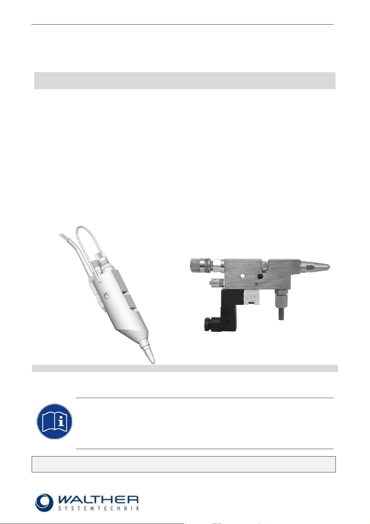
VMS-05 Standard
VMS-05 Special Design
NOTE
Please read the Assembly Instructions carefully before first using the incomplete device and
strictly adhere to the instructions!
This incomplete device may only be worked with and worked on by persons who are
familiar with the Assembly Instructions and the current regulations for industrial safety and
accident prevention.
Assembly Instructions
Hand Dosing Valve VMS-05
Article Numbers: Standard
V05-…
Special Design
V05-033040028012070
V05-253040028012070
V05-253080028012070
Always keep this translated version of the ‘original Assembly Instructions’ at the device!
The instructions have to be close at hand any time!
Page 2

Rev. 1.1
Assembly Instructions - Full-Jet Valve VMS-05
Page 2 of 25
Walther Systemtechnik GmbH – D 76726 Germersheim
Telefon: +49 (0)7274-7022-0 Telefax: +49 (0)7274-7022-91
http://www.walther-2000.de – info@walther-2000.de
Table of Contents
Page
EC DECLARATION OF INCORPORATION ....................................................................................................................... 4
1 INTRODUCTION ................................................................................................................................................. 5
1.1 TARGET GROUP OF THE ASSEMBLY INSTRUCTIONS ............................................................................................................ 5
1.2 LIST OF SIGNS AND SYMBOLS ....................................................................................................................................... 5
2 SAFETY............................................................................................................................................................... 5
2.1 GENERAL INFORMATION ............................................................................................................................................. 5
2.2 DANGERS FROM RESIDUAL ENERGY ............................................................................................................................... 5
2.3 WARRANTY AND LIABILITY ........................................................................................................................................... 5
2.4 CORRECT USE ........................................................................................................................................................... 6
2.5 INCORRECT USE ........................................................................................................................................................ 6
2.6 QUALIFICATIONS OF PERSONNEL ................................................................................................................................... 6
3 TRANSPORT ....................................................................................................................................................... 7
3.1 PACKAGING .............................................................................................................................................................. 7
3.2 TASKS BEFORE TRANSPORT .......................................................................................................................................... 7
4 DESCRIPTION OF FUNCTION .............................................................................................................................. 7
4.1 DESIGNATED PURPOSE OF THE INCOMPLETE DEVICE ......................................................................................................... 7
4.2 TECHNICAL DATA ....................................................................................................................................................... 8
4.3 TYPE LABEL .............................................................................................................................................................. 8
5 INITIAL START-UP ............................................................................................................................................... 9
5.1 MOUNTING AND INSTALLATION .................................................................................................................................... 9
5.2 HOSE MOUNTING...................................................................................................................................................... 9
5.3 ADJUSTING THE INCOMPLETE DEVICE .......................................................................................................................... 10
5.4 OPERATING ELEMENTS STANDARD .............................................................................................................................. 10
5.5 OPERATING ELEMENTS SPECIAL DESIGN ....................................................................................................................... 10
6 OPERATION ..................................................................................................................................................... 11
6.1 GENERAL INFORMATION ........................................................................................................................................... 11
6.2 OPERATION INSTRUCTIONS / OPERATING CONDITIONS .................................................................................................... 11
7 TAKING OUT OF SERVICE ................................................................................................................................. 12
7.1 SHORT INTERRUPTION .............................................................................................................................................. 12
7.2 LONG-TERM INTERRUPTION ....................................................................................................................................... 12
7.3 SHUTDOWN OF DEVICE ............................................................................................................................................. 12
8 MAINTENANCE AND REPAIR ............................................................................................................................ 13
8.1 GENERAL INFORMATION ........................................................................................................................................... 13
8.2 CLEANING .............................................................................................................................................................. 13
8.3 REPLACING NEEDLE AND NOZZLE ................................................................................................................................ 13
8.4 REPLACING THE SEALING BUSHING .............................................................................................................................. 14
8.5 INSERTING SEALINGS AND O-RINGS............................................................................................................................. 14
8.6 SPARE PARTS .......................................................................................................................................................... 15
8.7 ROUTINE TASKS ....................................................................................................................................................... 15
8.8 CUSTOMER SERVICE / SUPPORT .................................................................................................................................. 15
9 TROUBLESHOOTING ........................................................................................................................................ 16
9.1 GENERAL INFORMATION ........................................................................................................................................... 16
9.2 MALFUNCTIONS ...................................................................................................................................................... 16
10 APPENDIX ........................................................................................................................................................ 17
10.1 VMS-05 STANDARD ........................................................................................................................................... 17
10.1.1 Dimensioned Drawing VMS-05 Standard ............................................................................................. 17
Page 3

Rev. 1.1
Assembly Instructions - Full-Jet Valve VMS-05
Page 3 of 25
Walther Systemtechnik GmbH – D 76726 Germersheim
Telefon: +49 (0)7274-7022-0 Telefax: +49 (0)7274-7022-91
http://www.walther-2000.de – info@walther-2000.de
10.1.2 Spare Part Drawing VMS-05 Standard ................................................................................................. 18
10.1.3 Spare List VMS-05 Standard ................................................................................................................. 19
10.2 VMS-05 SPECIAL DESIGN .................................................................................................................................... 20
10.2.1 Dimensioned Drawing VMS-05 Special Design MV LV (long version) ................................................... 20
10.2.2 Dimensioned Drawing VMS-05 Special Design MV KV (short version) ................................................. 20
10.2.3 Spare Part Drawing VMS-05 Special Design ......................................................................................... 21
10.2.4 Spare Part List VMS-05 Special Design ................................................................................................. 22
10.3 ARTICLE NUMBERS FOR NOZZLES, NOZZLE NEEDLES AND MAGNETIC VALVES .................................................................. 23
10.4 ACCESSORIES ..................................................................................................................................................... 25
10.5 DATA SHEET MICRO SWITCH 97190003 ................................................................................................................ 25
Page 4

Rev. 1.1
Assembly Instructions - Full-Jet Valve VMS-05
Page 4 of 25
Walther Systemtechnik GmbH – D 76726 Germersheim
Telefon: +49 (0)7274-7022-0 Telefax: +49 (0)7274-7022-91
http://www.walther-2000.de – info@walther-2000.de
EC Declaration of Incorporation
in accordance with EU Machinery Directive 2006/42/EU, dated 17 May 2006, Appendix II B
We herewith confirm that the below mentioned incomplete device meets the basic requirements for safety
and health as stated in EU Machinery Directive 2006/42/EU for its design and construction as well as for the
configuration released by us on the market. This machine component will not be operated before it has been
determined that the incomplete system where the machine component will be installed also meets the
requirements of the Directive (2006/42/EG).
Manufacturer
Walther Systemtechnik GmbH
Hockenheimer Straße 3
D- 76726 Germersheim
Description
VMS-05 Hand Dosing Valve, Article No. V05-…
We also declare the conformity with other, product-relevant directives/guidelines:
Mach. Direct. 2006/42/EU App. I, Clause: 1.1.2, 1.1.3, 1.1.5, 1.1.6, 1.3.2, 1.3.3,
1.3.4, 1.5.1, 1.5.9
EMC- Directive 2014/30/EU, dated 26. February 2014
Applied harmonized standards, in particular:
DIN EN ISO 12100 Safety of Machinery – General Design Principles –
Risk Assessment and Risk Reduction (ISO
12100:2010)
In addition, we also confirm that the special documentation according to Appendix VII Part B has
been prepared.
The manufacturer, respectively his authorized representative obligates himself to submit this documentation
to the market surveillance authorities, if requested.
This EC Declaration of Incorporation becomes invalid if the incomplete device will be altered or changed
without consent of Walther Systemtechnik GmbH.
Authorized representative for Technical Documentation:
Stefan Hirl, Hockenheimer Straße 3, D- 76726 Germersheim
Germersheim, 19 April 2016
(Place, Date) (Stefan Hirl, Management)
Page 5
Rev. 1.1
Assembly Instructions - Full-Jet Valve VMS-05
Page 5 of 25
Walther Systemtechnik GmbH – D 76726 Germersheim
Telefon: +49 (0)7274-7022-0 Telefax: +49 (0)7274-7022-91
http://www.walther-2000.de – info@walther-2000.de
DANGER
Describes a potentially dangerous situation.
Death, grievous bodily harm or severe material damage WILL occur if the respective
measures of precaution have not been taken
WARNING
Describes a potentially dangerous situation.
Death, grievous bodily harm or severe material damage MAY occur if the respective
measures of precaution have not been taken.
CAUTION
Describes a potentially dangerous situation.
Slight injuries CAN occur if the respective measures of precaution have not been
taken. This signal word is also used to describe possible property damages.
IMPORTANT
Indicates tips for usage and other particularly useful information.
No dangerous situation.
1 Introduction
1.1 Target Group of the Assembly Instructions
Operating Personnel
Maintenance Personnel
1.2 List of Signs and Symbols
The assembly instructions warn users of operations which may put their health at risk.
The warnings are indicated by combinations of text and symbols as follows:
2 Safety
2.1 General Information
The construction of this incomplete device is according to the latest technology and is absolutely reliable.
The individual components as well as the complete device are continuously checked by our quality management.
2.2 Dangers from Residual Energy
Please instruct the operating personnel on the respective measures to be taken against the occurrence of
mechanical, hydraulic, pneumatic and electric / electronic residual energies.
2.3 Warranty and Liability
According to the conditions laid down by the German Engineering Association (VDMA), Walther Systemtechnik GmbH has a guarantee of 12 months under normal European operating conditions on its own
parts (spare parts are excluded); or according to the conditions of the manufacturer.
This guarantee can only be granted by Walther Systemtechnik GmbH, if:
the user has thorough knowledge of the content of the assembly instructions;
the user follows the instructions and notes contained in the assembly instructions;
the user does not rebuild or make changes on parts of the device without prior consent of WST Sys-
temtechnik GmbH.
Page 6
Rev. 1.1
Assembly Instructions - Full-Jet Valve VMS-05
Page 6 of 25
Walther Systemtechnik GmbH – D 76726 Germersheim
Telefon: +49 (0)7274-7022-0 Telefax: +49 (0)7274-7022-91
http://www.walther-2000.de – info@walther-2000.de
WARNING
Do not use solvents or cleaners from the chlorinated hydrocarbon group; for example,
1.1.1 trichloromethane or methylene chloride can react explosively with aluminum or
galvanized parts.
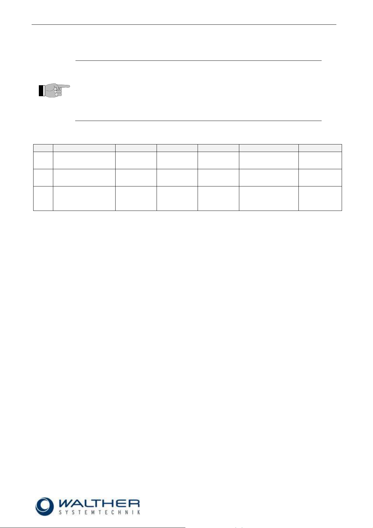
Personnel
Task
Instructed
Personnel
Personnel with Technical
Qualification
Specialist
Supervisor
Packaging, Transport
X
-
-
-
Commissioning
X
X
-
Operation
X
-
Troubleshooting, general
X
X
-
Troubleshooting
mechanical
-
X
-
-
Troubleshooting electrical
-
-
X
-
Setting up
-
X
-
-
Maintenance
-
X
-
-
Repair
-
X
X
-
Taking out of service,
Storage
-
X
X
-
2.4 Correct Use
The VMS-05 Hand Dosing Valve is suitable for the application of media such as sealants, adhesives, greases, pastes and oils. Under no circumstance will aggressive media be processed! In case of doubt, please
contact the manufacturer if a certain medium is suitable for this device.
The VMS-05 Special Design valve is a needle valve and will be used for processing materials which can be
sprayed in continuous or intermitting operation. Under no circumstances shall aggressive media such as
acids, alkaline solutions, detergents, chemicals or others be sprayed. If you are not sure, please contact the
manufacturer if a certain spray medium is suitable for this device.
2.5 Incorrect Use
Operating the incomplete device with insufficient knowledge about the operation, maintenance and care
of the device.
Making changes, extensions or alterations on the incomplete device that may hamper its safety without
the prior consent of Walther Systemtechnik GmbH.
Operating the incomplete device with defective safety installations or not properly attached or malfunc-
tioning safety devices.
Using unsuitable materials.
Handling the incomplete device while energized
2.6 Qualifications of Personnel
Only trained and instructed personnel may conduct work on the equipment.
The responsibilities of the personnel for assembly work, operation, repair work or maintenance work must be
clearly assigned to individuals!
Persons in training may work with the equipment only under supervision of an experienced person.
Page 7

Rev. 1.1
Assembly Instructions - Full-Jet Valve VMS-05
Page 7 of 25
Walther Systemtechnik GmbH – D 76726 Germersheim
Telefon: +49 (0)7274-7022-0 Telefax: +49 (0)7274-7022-91
http://www.walther-2000.de – info@walther-2000.de
CAUTION
The use of other media can cause functional failures, damages or even the destruction
of the device.
3 Transport
3.1 Packaging
The type of packaging depends on the individual mode of shipping. If not separately contracted, the
packaging is in accordance with the rules and regulations of Walther Systemtechnik GmbH. This rule is in
accordance with the Federal Association for Packaging HPE.
3.2 Tasks before Transport
The following has to be done before transport:
Disconnect all power lines.
The actual transport of the incomplete device and its individual parts requires special care in order to prevent
damages from external forceful impact or careless on- and off-loading. Depending on the mode of
transportation, suitable transport and load securing has to be selected. The incomplete device will be aligned
and leveled by appropriate fastening elements.
4 Description of Function
4.1 Designated Purpose of the Incomplete Device
Standard
The VMS-05 Hand Dosing Valve was designed for the application of sealants, adhesives, greases, pastes
and oils. The selected nozzle defines the actual application. Depending on the viscosity of the medium to be
applied, the application result can be individually adjusted through the nozzle size, the material supply
pressure and the needle stroke. The medium will be supplied via a material connection. The VMS-05 hand
dosing valve is a high-precision device which will be a long-term reliable tool if the following notes are
observed.
Operating the micro-switch (15) sends an electric impulse to a pilot valve (not included in scope of delivery).
This pilot valve will then send an air impulse to the Dosing Valve which will start the spraying process.
A pilot valve can come as magnetic valve. Is this the case, the Dosing Valve will spray as long as the microswitch is pushed.
A pilot valve can also come as a time-control. In this case, the Dosing Valve will spray according to the preset time, and the micro-switch does not have to be pushed constantly.
Special Design
Due to their low weight and a very compact design, the valves of the VMS-05 Special Design series MV
LV/KV are ideally suitable for all applications with only little space for installation in machines or robots.
Using LV-nozzles (long versions) allows you to install the devices with an incline towards each other, but not
much more mounting space is required. The valves are predominantly used for the application of sealants,
adhesives and oils. Depending on the nozzle size, media with different viscosities can be processed. The
VMS-05 Special Design MV LV/KV valves are high-precision devices which will be a long-term reliable tool
if the following notes are observed.
The valve is a pneumatically controlled application device for processing materials such as sealants,
adhesives, greases, paints, oils etc. A mutual application of air on the working piston results in opening and
closing of the nozzle needle. When the control air is turned off or fails, the spring closes the nozzle needle.
The spraying medium is supplied from a pressured container or a pump. The valve operates with a full jet.
Page 8

Rev. 1.1
Assembly Instructions - Full-Jet Valve VMS-05
Page 8 of 25
Walther Systemtechnik GmbH – D 76726 Germersheim
Telefon: +49 (0)7274-7022-0 Telefax: +49 (0)7274-7022-91
http://www.walther-2000.de – info@walther-2000.de
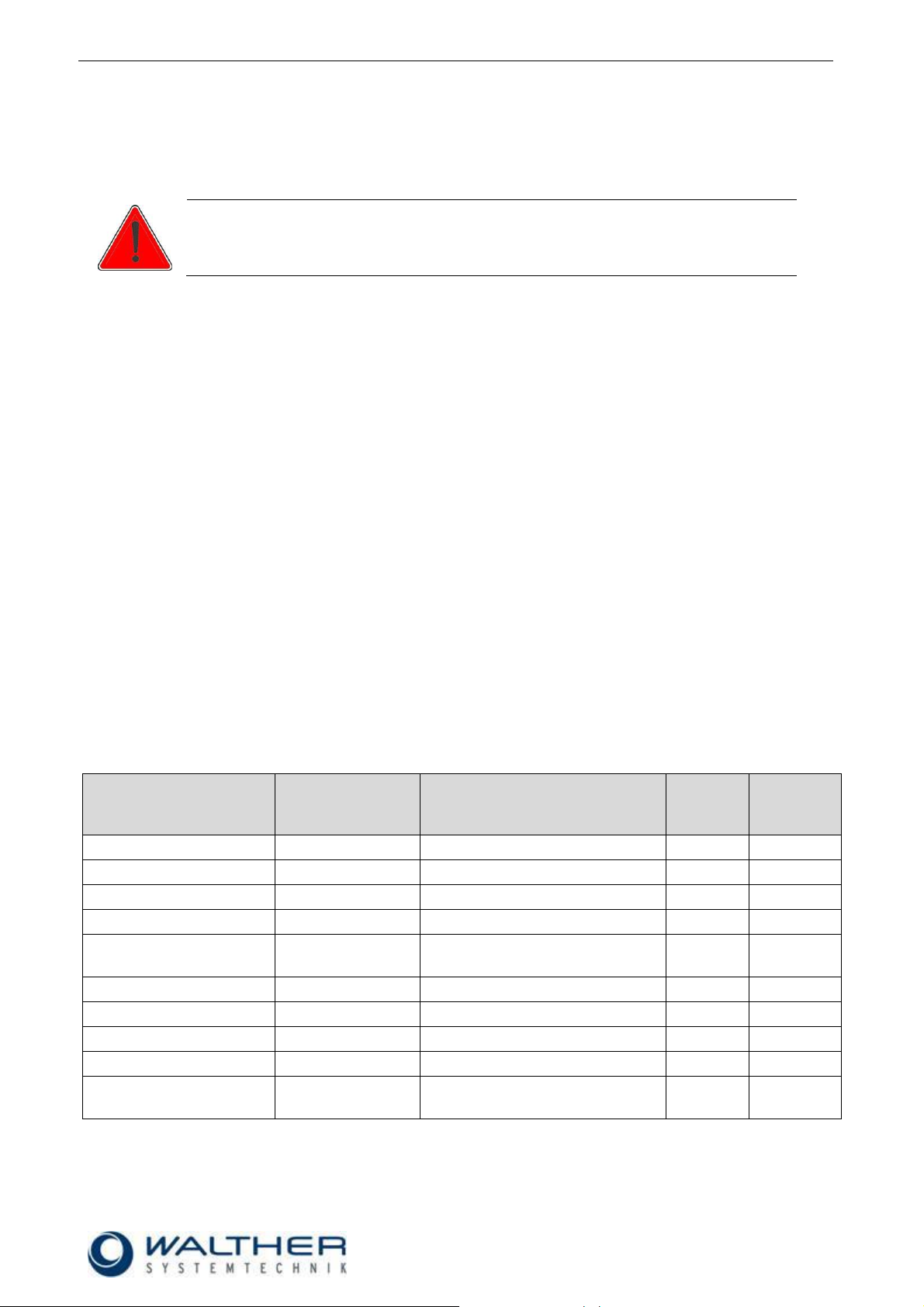
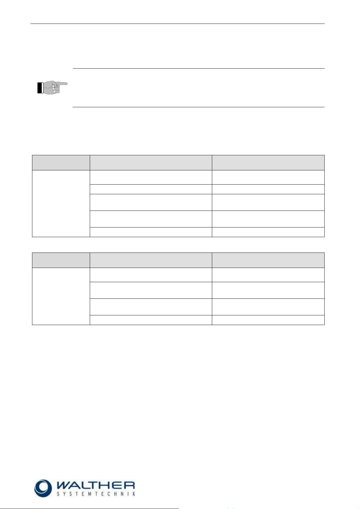
4.2 Technical Data
Dimensions [mm] KV-type
ca. 45 x 250
Weight [g]
ca. 700
Sealing material
Viton
Control air pressure [bar]
min. 6
Material pressure [bar]
max. 100
Dimensions [mm] KV-type
ca. 122 x 15 x 75 (see Appendix!)
Dimensions [mm] LV-type
ca. 142 x 15 x 75 (see Appendix!)
Weight [g]
ca. 265
Sealing material
Viton
Control air pressure [bar]
min. 6
Material pressure [bar]
max. 30
General Data - Standard
Energy Supply
General Data - Special Design
Energy Supply
4.3 Type Label
The type label has been etched in near the material connection. The serial number will be hammered into
the type label.
Page 9

Rev. 1.1
Assembly Instructions - Full-Jet Valve VMS-05
Page 9 of 25
Walther Systemtechnik GmbH – D 76726 Germersheim
Telefon: +49 (0)7274-7022-0 Telefax: +49 (0)7274-7022-91
http://www.walther-2000.de – info@walther-2000.de
Control air
Material
Control air
open
Material
Control air
close
5 Initial Start-up
5.1 Mounting and Installation
Connect the VMS-05 Hand Dosing Valve with a pressured container or a pump via the material connection
(4). Connect the micro-switch (15) with a pilot valve (magnetic valve or time control or other). Adjust material
pressure at the pressured container or the pump (max. 20bar). When you now operate the micro-switch,
material will be discharged from the nozzle.
The VMS-05 Special Design valves can be installed in any position. The distance to the application area
depends on the desired application image.
An intermittent operation of the device will cause certain vibrations. Therefore make sure that the device is
safely and securely fixed and installed. The device comes with two borings of 5mm diameter in the valve
body which can be used for a solid installation. Try to avoid extremely large vibrations (transfer from
machines to valve).
5.2 Hose Mounting
Standard
Three functional hoses will connected as follows:
1. Control air (black) to plug-in nipple (open 7 SA)
2. Control air (black) to plug-in nipple (close 7 SZ)
3. Material (transparent) to 1/4"-connection (4)
Special Design
Two functional hoses will be connected as follows:
1. Control air to M5-connection (21.0.0)
2. Material to 1/4"-connection (21.20)
Page 10
Rev. 1.1
Assembly Instructions - Full-Jet Valve VMS-05
Page 10 of 25
Walther Systemtechnik GmbH – D 76726 Germersheim
Telefon: +49 (0)7274-7022-0 Telefax: +49 (0)7274-7022-91
http://www.walther-2000.de – info@walther-2000.de
IMPORTANT
Do not turn the raster-needle locking screw any further counter-clockwise if no more
stops are noticeable while turning it! The maximum needle stroke adjustment has been
reached already.
Further turning will cause the raster-needle locking screw to jump out!!
IMPORTANT
Nozzle and needle can be damaged by wrong handling. Only decrease the material
flow (by a right turn of the regulating screw) if material spills out. Do not turn the regulating screw further to the right after the nozzle is closed!
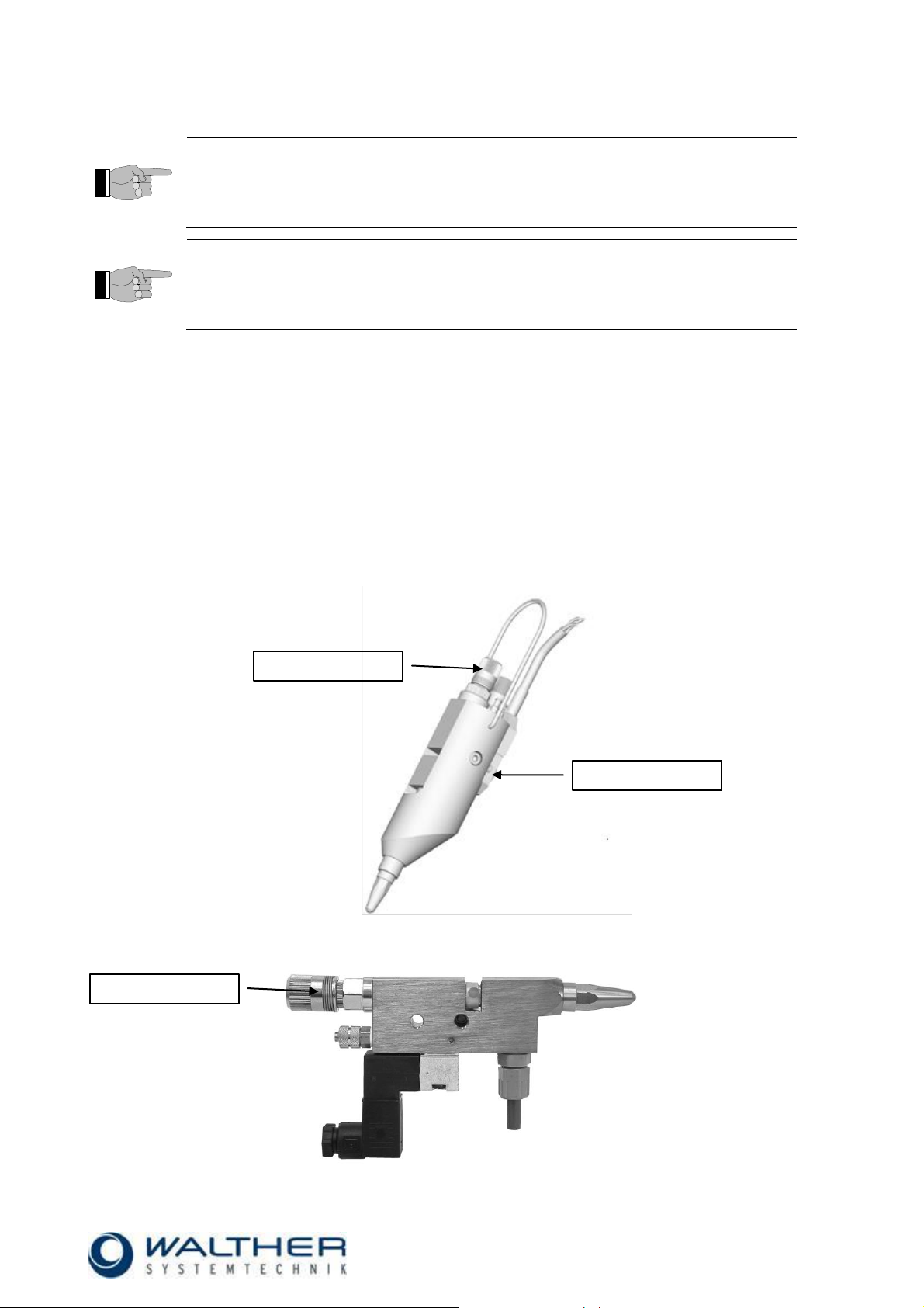
Regulating screw
Regulating screw
Release button
5.3 Adjusting the Incomplete Device
Standard
The individual material quantity can be adjusted with the needle-stroke regulation (10, 11 or 12).
Functional Principle:
Turn the raster head/regulating spindle to the right: decrease the material quantity
Turn the raster head/regulating spindle to the left: increase the material quantity
Special Design
The amount of material can be regulated via the stroke adjustment of the needle. A left turn of the locking
screw increases the material amount. A fine precision thread affects a needle rise that results in an adjustment of 0.5 mm with each turn of the adjusting knob
5.4 Operating Elements Standard
5.5 Operating Elements Special Design
Page 11
Rev. 1.1
Assembly Instructions - Full-Jet Valve VMS-05
Page 11 of 25
Walther Systemtechnik GmbH – D 76726 Germersheim
Telefon: +49 (0)7274-7022-0 Telefax: +49 (0)7274-7022-91
http://www.walther-2000.de – info@walther-2000.de
CAUTION
Never point the jet at people. The wearing of eye protection is strongly recommended.
The spraying process can create noise depending on the air and fluid pressures used.
Ear protection should be worn, if required.
WARNING
Danger caused by flammable, harmful fluid. Always follow the safety instructions on the
container or the safety data sheet for the fluid.
IMPORTANT
Accident prevention directions will be strictly followed when applying high material
pressures. Please strictly follow the following instructions when planning and
constructing application systems.
IMPORTANT
The base for an optimum setting of the application image is a device-specific
adjustment. Basic values from lab tests can be used as references. However these
have to be adjusted individually. Parameters such as nozzle size, opening time,
opening stroke, material pressure and maybe also temperature have to be combined.
6 Operation
6.1 General Information
This device will only be operated if the safety-related equipment is permanently effective and not suspended
during operation or altered in its intended effectiveness.
6.2 Operation Instructions / Operating Conditions
The valves of the VMS-05 Special Design series generally operate with a control air pressure of 6 bar and
material pressures of up to 30 bar.
The valves are able to perform contact-applications or also contact-free applications. The valves can be
controlled for intermittent or continuous use. According to the individual application, the control air must be
adjusted to the operating cycles and to the higher or lower material pressures. 40 tacts per second can be
reached under appropriate operating conditions (material pressure, control air pressure, needle stroke, and
short conductions).
The amount of material can be regulated via the stroke adjustment of the needle. A left turn of the locking
screw increases the material amount. A fine precision thread affects a needle rise that results in an adjustment of 0.5 mm with each turn of the adjusting knob.
For longer times of standstill, the material can remain in the valve, if it remains under pressure (no contact to
outside air).
Page 12

Rev. 1.1
Assembly Instructions - Full-Jet Valve VMS-05
Page 12 of 25
Walther Systemtechnik GmbH – D 76726 Germersheim
Telefon: +49 (0)7274-7022-0 Telefax: +49 (0)7274-7022-91
http://www.walther-2000.de – info@walther-2000.de
IMPORTANT
Please follow the Operating Manual!
IMPORTANT
Please follow the maintenance guidelines!
IMPORTANT
Please follow the maintenance guidelines!
7 Taking out of Service
7.1 Short Interruption
A short interruption (15 min or more) has to be followed by a clean spraying.
7.2 Long-term Interruption
The following has to be observed for a long-term interruption of the device/machine:
Depressurize material supply lines
Remove air cap and clean nozzle with a special thinner and a soft cloth. Make sure that no cloth fibers
are left on the nozzle tip.
7.3 Shutdown of Device
The following is important for a shutdown of the machine / device:
Clean full-jet valve with a special thinner.
Page 13

Rev. 1.1
Assembly Instructions - Full-Jet Valve VMS-05
Page 13 of 25
Walther Systemtechnik GmbH – D 76726 Germersheim
Telefon: +49 (0)7274-7022-0 Telefax: +49 (0)7274-7022-91
http://www.walther-2000.de – info@walther-2000.de
CAUTION
Before starting any maintenance or repair work, ensure that all air-operated tools are
depressurized and disconnected from the air supply.
Before opening the dosing pen it must be disconnected from the air and fluid supply.
Otherwise, ejected components can cause injuries.
IMPORTANT
Only use soft brushes for outside cleaning of the nozzle tips. Never use metal tools
with sharp edges.
CAUTION
First depressurize all connections.
8 Maintenance and Repair
8.1 General Information
The valves of the VMS-05 series are high-quality precision devices which will not fail if treated correctly and
will operate almost maintenance-free. Always keep clean and observe minimum instructions to maintain a
long life of the valve. Always use clean and filtered material only. The control air must also be clean and
should be slightly oiled, if necessary. Maintenance also depends on the individual operating conditions and
the type of media used.
8.2 Cleaning
Wash equipment thoroughly after use to remove residues and dirt, especially if nozzle needle, sealing
bushing or nozzle have to be exchanged.
Use the thinner for sprayable media as detergent. A daily cleansing rinse will remove residues of the
sprayable medium and clean almost all parts and channels which have been in contact with the sprayable
medium.
8.3 Replacing Needle and Nozzle
Standard Needle (8) and Nozzle (1)
First unscrew screws (14) and then remove valve from device body (13). Completely unscrew needle lock
(10, 11 or 12). Unscrew nozzle (1). From the nozzle side, carefully push out needle (8) to the back. Reassemble with slightly greased new parts in reverse order. We do not recommend reusing old needles.
Piercing of slightly dirty needles through the needle gaskets (pos. 5.1) can cause leakages.
Special Design Needle (7.10) and Nozzle (2.10)
Completely unscrew raster-needle lock (pos. 9.02) and nozzle (pos. 2.10). Remove needle spring (8.10) and
carefully push out the needle (pos. 7.10) towards the nozzle end. Re-assemble with slightly greased new
parts in reverse order. We do not recommend reusing old needles. Piercing of slightly dirty needles through
the needle gaskets (pos. 5.50) can cause leakages.
Page 14

Rev. 1.1
Assembly Instructions - Full-Jet Valve VMS-05
Page 14 of 25
Walther Systemtechnik GmbH – D 76726 Germersheim
Telefon: +49 (0)7274-7022-0 Telefax: +49 (0)7274-7022-91
http://www.walther-2000.de – info@walther-2000.de
IMPORTANT
Gaskets and gasket holders can be damaged.
Do not use any sharp or pointed metallic implements for inserting the sealings!
8.4 Replacing the Sealing Bushing
Standard Sealing Bushing (6)
Unscrew screws (14) and remove valve from device body (13). Completely unscrew needle lock (pos. 10, 11
or 12) and nozzle (pos. 1). Carefully push out the needle (pos. 8) towards the nozzle end. Then unscrew the
sealing sleeve (pos. 6.0.0) from the thread with a screwdriver. Since the outer O-ring (pos. 5.3) prevents the
sealing sleeve from falling through the mounting thread of the valve body (pos. 3), it is necessary to push the
sealing sleeve together with O-ring (pos. 5.3) carefully backwards through the thread using a thin strip of
metal (0.5 – 1.0 mm) which you push between the recess in the body and flat in front of the front end of the
sealing sleeve. You can then take the sealing sleeve out of the enclosure.
Special Design Sealing Bushing (6.00)
Completely unscrew raster-needle lock (pos. 9.02) and nozzle (pos. 2.10). Carefully push out the needle
(pos. 7.10) towards the nozzle end. Then unscrew the sealing sleeve (pos. 6.00) from the thread with a
screwdriver. Since the outer O-ring (pos. 5.30) prevents the sealing sleeve from falling through the mounting
thread of the valve body (pos. 4.10), it is necessary to push the sealing sleeve together with O-ring (pos.
5.30) carefully backwards through the thread using a thin strip of metal (0.5 – 1.0 mm) which you push
between the recess in the body and flat in front of the front end of the sealing sleeve. You can then take the
sealing sleeve out of the enclosure.
8.5 Inserting Sealings and O-Rings
Standard
If a complete packing sleeve (pos. 6) is not available as a replacement, the old gaskets must be removed
and replaced with new ones. In order to do so, the sealing sleeve must be thoroughly cleaned so that no
particles of the previous spraying fluid impair the installation of the new gaskets. The O-ring seats should be
lightly greased with a lubricant (technical Vaseline). First insert O-ring (pos. 6.2) into the rear hole of the
sealing sleeve until it reaches the end. Then insert O-ring (pos. 5.3) into the outer groove. Insert the special
form gasket (pos. 5.1) into the front seat. Since this form gasket is not symmetrical, the side with the larger
boring must be inserted facing forwards, i.e. it must point in the direction of the nozzle after the complete
sealing sleeve has been installed. Lightly grease the sealing sleeve (pos. 6) and insert it back into the valve
body (pos. 3). Use a screwdriver to carefully push it through the mounting thread together with the outer Oring (pos. 5.3) without twisting it. Then screw the sealing sleeve into the thread (gently tighten).
Do not use any metallic or sharp-edged aids or tools when you insert the O-rings and the form gasket. Despite all its outstanding sealing qualities, the form gasket is a sensitive precision component, which cannot
tolerate impacts or pressure.
Special Design
If a complete packing sleeve (pos. 6.00) with integrated material sealing set (5.00) is not available as a replacement, the old gaskets must be removed and replaced with new ones. In order to do so, the sealing
sleeve must be thoroughly cleaned so that no particles of the previous spraying fluid impair the installation of
the new gaskets. The O-ring seats should be lightly greased with a lubricant (technical Vaseline). First insert
O-ring (pos. 6.20) into the rear hole of the packing sleeve until it reaches the end. Then insert O-ring (pos.
5.30) into the outer groove. Insert the special form gasket (pos. 5.50) into the front seat. Since this form gasket is not symmetrical, the side with the larger boring must be inserted facing forwards, i.e. it must point in
the direction of the nozzle after the complete packing sleeve has been installed. Lightly grease the sealing
sleeve (pos. 6.00) and insert it back into the valve body (pos. 4.10). Use a screwdriver to carefully push it
through the mounting thread together with the outer O-ring (pos. 5.3.0) without twisting it. Then screw the
sealing sleeve into the thread (gently tighten).
Do not use any metallic or sharp-edged aids or tools when you insert the O-rings and the special form
gasket. Despite all its outstanding sealing qualities, the special form gasket is a sensitive precision
component, which cannot tolerate impacts or pressure.
Page 15
Rev. 1.1
Assembly Instructions - Full-Jet Valve VMS-05
Page 15 of 25
Walther Systemtechnik GmbH – D 76726 Germersheim
Telefon: +49 (0)7274-7022-0 Telefax: +49 (0)7274-7022-91
http://www.walther-2000.de – info@walther-2000.de
IMPORTANT
Only use original spare parts from the manufacturer!
Wrong or defective spare parts from other manufacturers can damage the device. If
other than original spare parts of the manufacturer will be used, all obligations from the
manufacturer or his sales partners, such as guarantees, service contracts etc will be
forfeited without further notice.
No.
Description
Cleaning
Lubricating
Inspecting
Additional tasks
Frequency
1.
connections
(tightness)
X
monthly
2.
nozzle
X X
exchange if
damaged
monthly
3.
complete valve
X
check for wear
after 10 mio.
switching
operations
Walther Systemtechnik GmbH
Hockenheimer Straße 3
D-76726 Germersheim
Germany
Phone ++49(0)7274-7022-0
Telefax ++49(0)7274-7022-91
Email info@walther-2000.de
Internet www.walther-2000.de
8.6 Spare Parts
8.7 Routine Tasks
8.8 Customer Service / Support
Page 16
Rev. 1.1
Assembly Instructions - Full-Jet Valve VMS-05
Page 16 of 25
Walther Systemtechnik GmbH – D 76726 Germersheim
Telefon: +49 (0)7274-7022-0 Telefax: +49 (0)7274-7022-91
http://www.walther-2000.de – info@walther-2000.de
IMPORTANT
First check all supply lines for connection and serviceability.
Fault
Possible Cause
Action
Nozzle needle does
not open
Not enough control air supplied
Check if enough control air available (5 6 bar).
Valve does not activate
Check if micro-switch is defective
Leakages
Check if O-Rings (6.2 and 8.1) are
defective.
Nozzle needle (8) is sticky within the
sealing screw (6).
Disassemble and clean.
Needle stroke is set too low.
Check if needle stroke is correctly set.
Fault
Possible Cause
Action
Nozzle needle does
not open
Not enough control air supplied
Check if enough control air available (5 6 bar).
Leakages
Check if O-Rings (6.20 and 7.40) are
defective.
Needle (7.10) is sticky within the sealing
screw (6.10).
Disassemble and clean.
Needle stroke is set too low.
Check if needle stroke is correctly set.
9 Troubleshooting
9.1 General Information
In case of serious problems that cannot be resolved, please contact the Walther Systemtechnik GmbH customer service.
9.2 Malfunctions
Standard
Special Design
Page 17
Rev. 1.1
Assembly Instructions - Full-Jet Valve VMS-05
Page 17 of 25
Walther Systemtechnik GmbH – D 76726 Germersheim
Telefon: +49 (0)7274-7022-0 Telefax: +49 (0)7274-7022-91
http://www.walther-2000.de – info@walther-2000.de
10 Appendix
10.1 VMS-05 Standard
10.1.1 Dimensioned Drawing VMS-05 Standard
Page 18
Rev. 1.1
Assembly Instructions - Full-Jet Valve VMS-05
Page 18 of 25
Walther Systemtechnik GmbH – D 76726 Germersheim
Telefon: +49 (0)7274-7022-0 Telefax: +49 (0)7274-7022-91
http://www.walther-2000.de – info@walther-2000.de
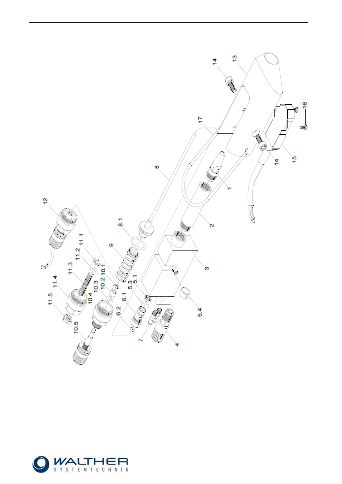
10.1.2 Spare Part Drawing VMS-05 Standard
Page 19

Rev. 1.1
Assembly Instructions - Full-Jet Valve VMS-05
Page 19 of 25
Walther Systemtechnik GmbH – D 76726 Germersheim
Telefon: +49 (0)7274-7022-0 Telefax: +49 (0)7274-7022-91
http://www.walther-2000.de – info@walther-2000.de
10.1.3 Spare List VMS-05 Standard
Dwg No.
Art.-No.
Qty
Description
1 * 1
Nozzle, stainless
1.1
97320005
1
Needle guide
1.2
97410053
1
Hexagon retaining ring
Pos. 1.1 and 1.2 are not part of the drawing
2 * 1
Nozzle tube
3
97510158
1
Main body VMS-05 Standard
4
97220139
1
Reduction screw-joint, stainless steel 1/4"AG - 1/8"AG
5
97640102
1
Material sealings
5.1
97640004
1
Variseal
5.3
97640021
1
O-Ring Viton
5.4
97640101
1
Plastic protection sleeve
6
97810014
1
Sealing screw, complete
6.1
97810013
1
Sealing screw
6.2
97640026
1
O-Ring
7
97220288
2
Plug-in nipple, brass M5
8 * 1
Nozzle needle, complete
8.1
97640007
1
O-Ring Viton
9
97820044
1
Pressure spring
10
97900021
1
Raster-needle lock
10.1
97620017
1
Safety washer
10.2
97320098
1
Stop sleeve
10.3
97640027
1
O-Ring Viton
10.4
97220291
1
Raster-needle locking screw (incl. 10.3)
10.5
97610093
1
Needle stroke raster head
11
97900013
1
Normal lock
11.1
97620007
1
Safety washer
11.2
97640032
1
O-Ring Viton
11.3
97610107
1
Regulating spindle
11.4
97220115
1
Locking screw
11.5
97410007
1
Nut
12
97900044
1
Raster-needle lock with electric needle sensor
13
97510159
1
Device body – handle
14
97610011
2
Cylinder screw with inner hex
15
97190003
1
Micro-switch
16
97610005
2
Cylinder screw with slot
17
97910340
1
Hanging clamp
IMPORTANT
Always indicate the inscribed serial numbers when ordering spare parts!
* Article numbers can be found on the following pages.
Please indicate the required size when ordering spare parts for nozzle sets.
Available sizes: 0.3/0.5/0.7/1.0/1.5/2.0mm
Nozzle set = Nozzle needle and nozzle (should always be replaced together)
Page 20

Rev. 1.1
Assembly Instructions - Full-Jet Valve VMS-05
Page 20 of 25
Walther Systemtechnik GmbH – D 76726 Germersheim
Telefon: +49 (0)7274-7022-0 Telefax: +49 (0)7274-7022-91
http://www.walther-2000.de – info@walther-2000.de
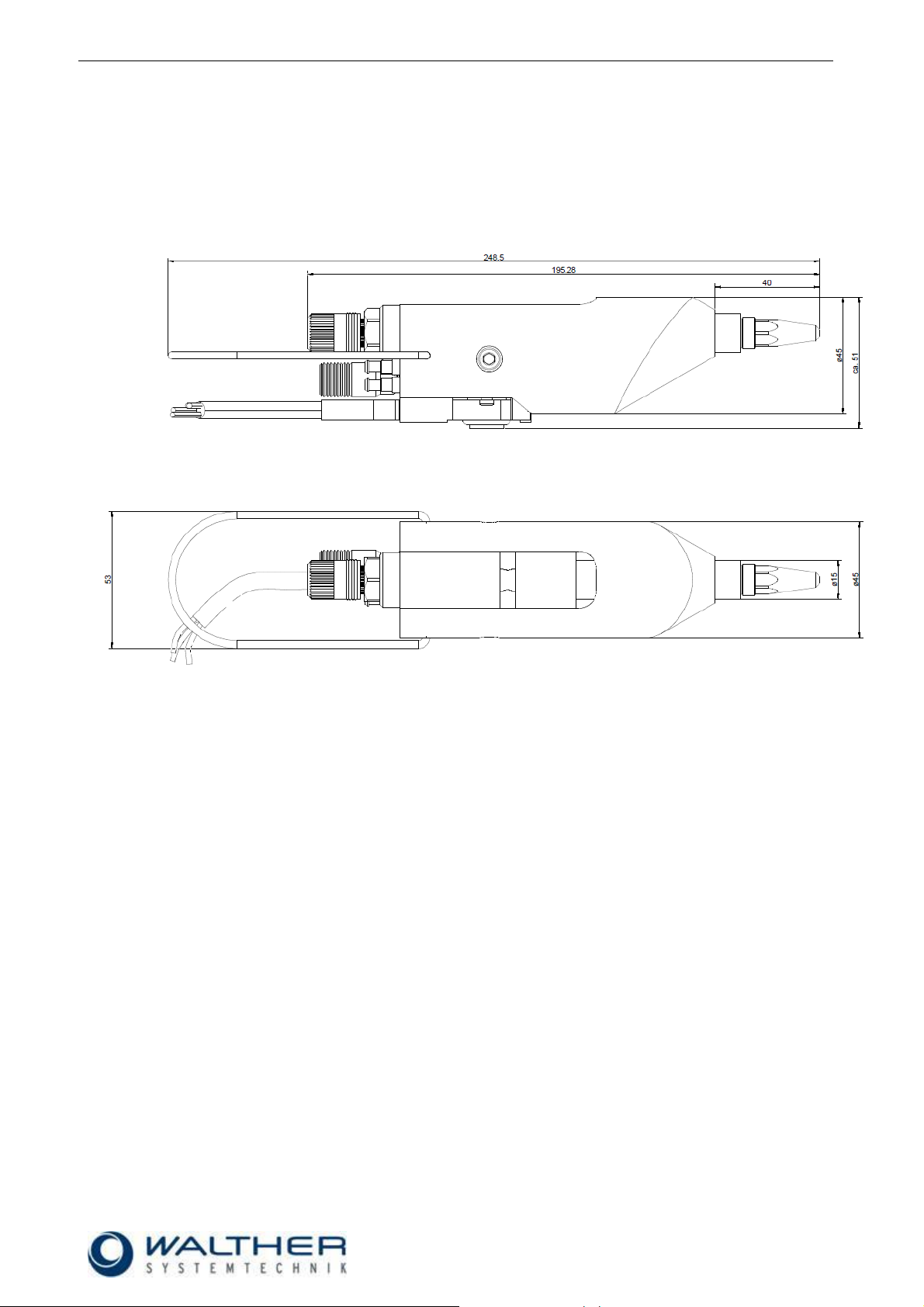
10.2 VMS-05 Special Design
10.2.1 Dimensioned Drawing VMS-05 Special Design MV LV (long version)
10.2.2 Dimensioned Drawing VMS-05 Special Design MV KV (short version)
Page 21

Rev. 1.1
Assembly Instructions - Full-Jet Valve VMS-05
Page 21 of 25
Walther Systemtechnik GmbH – D 76726 Germersheim
Telefon: +49 (0)7274-7022-0 Telefax: +49 (0)7274-7022-91
http://www.walther-2000.de – info@walther-2000.de
10.2.3 Spare Part Drawing VMS-05 Special Design
Page 22

Rev. 1.1
Assembly Instructions - Full-Jet Valve VMS-05
Page 22 of 25
Walther Systemtechnik GmbH – D 76726 Germersheim
Telefon: +49 (0)7274-7022-0 Telefax: +49 (0)7274-7022-91
http://www.walther-2000.de – info@walther-2000.de
Dwg No.
Art.-No.
Qty
Description
2.10 * 1
Nozzle, stainless steel
4.10
97510036
1
Main body VMS-05 MV, complete
5.00
97640107
1
Material sealing set
5.30
97640021
1
O-Ring Viton
5.40
97640101
1
Plastic protection sleeve
5.50
97640004
1
Variseal
6.00
97810014
1
Sealing screw, complete
6.10
97810013
1
Sealing screw
6.20
97640026
1
O-Ring
7.10 * 1
Nozzle needle, complete
7.40
97640007
1
O-Ring Viton
8.10
97820020
1
Pressure spring
9.02
97900008
1
Raster-needle lock
9.12
97610093
1
Needle stroke raster head
9.22
97220104
1
Raster locking screw SW 13
9.32
97640027
1
O-Ring Viton
9.42
97320022
1
Cylinder pin DIN 6325
9.52
97820000
1
Pressure spring
9.62
97610017
1
Threaded pin DIN 913
9.72
97320098
1
Stop sleeve
15.00 * 1
Magnetic valve
21.00
97220089
1
Screw joint, complete, SW 8
21.20
97220114
1
Double nipple, stainless steel, 1/4"AG-1/8"AG
IMPORTANT
Always indicate the inscribed serial numbers when ordering spare parts!
10.2.4 Spare Part List VMS-05 Special Design
* Article numbers can be found on the following pages.
Please indicate the required size when ordering spare parts for nozzle sets.
Available sizes: 0.2/0.3/0.4/0.5/0.6/0.7/0.8/1.0/1.2/1.5/2.0mm
Nozzle set = Nozzle needle and nozzle (should always be replaced together)
Page 23

Rev. 1.1
Assembly Instructions - Full-Jet Valve VMS-05
Page 23 of 25
Walther Systemtechnik GmbH – D 76726 Germersheim
Telefon: +49 (0)7274-7022-0 Telefax: +49 (0)7274-7022-91
http://www.walther-2000.de – info@walther-2000.de
*Nozzle, LV, stainless steel Standard
Dwg No
Article No.
Description
1
97210139
Nozzle, LV, 1.0 mm, Stainless steel
1
97210141
Nozzle, LV, 1.5 mm, Stainless steel
1
97210142
Nozzle, LV, 2.0 mm, Stainless steel
1
97210210
MG-Adapter, 0.8mm, M13 x 0.75
*Nozzle, LV, stainless steel Special Design
Dwg No
Article No.
Description
2.10
97210132
Nozzle, LV, 0.2 mm, Stainless steel
2.10
97210133
Nozzle, LV, 0.3 mm, Stainless steel
2.10
97210134
Nozzle, LV, 0.4 mm, Stainless steel
2.10
97210102
Nozzle, LV, 0.5 mm, Stainless steel
2.10
97210136
Nozzle, LV, 0.6 mm, Stainless steel
2.10
97210137
Nozzle, LV, 0.7 mm, Stainless steel
2.10
97210138
Nozzle, LV, 0.8 mm, Stainless steel
2.10
97210139
Nozzle, LV, 1.0 mm, Stainless steel
2.10
97210140
Nozzle, LV, 1.2 mm, Stainless steel
2.10
97210141
Nozzle, LV, 1.5 mm, Stainless steel
2.10
97210142
Nozzle, LV, 2.0 mm, Stainless steel
*Nozzle, KV, stainless steel Standard
Dwg No
Article No.
Description
1
97210144
Nozzle, KV, 0.3 mm, Stainless steel
1
97210146
Nozzle, KV, 0.5 mm, Stainless steel
1
97210148
Nozzle, KV, 0.7 mm, Stainless steel
1
97210153
Nozzle, KV, 2.0 mm, Stainless steel
1
97210210
MG-Adapter, 0.8mm, M13 x 0.75
*Nozzle, KV, stainless steel Special Design
Dwg No
Article No.
Description
2.10
97210143
Nozzle, KV, 0.2 mm, Stainless steel
2.10
97210144
Nozzle, KV, 0.3 mm, Stainless steel
2.10
97210145
Nozzle, KV, 0.4 mm, Stainless steel
2.10
97210146
Nozzle, KV, 0.5 mm, Stainless steel
2.10
97210147
Nozzle, KV, 0.6 mm, Stainless steel
2.10
97210148
Nozzle, KV, 0.7 mm, Stainless steel
2.10
97210149
Nozzle, KV, 0.8 mm, Stainless steel
2.10
97210150
Nozzle, KV, 1.0 mm, Stainless steel
2.10
97210151
Nozzle, KV, 1.2 mm, Stainless steel
2.10
97210152
Nozzle, KV, 1.5 mm, Stainless steel
2.10
97210153
Nozzle, KV, 2.0 mm, Stainless steel
10.3 Article Numbers for Nozzles, Nozzle Needles and Magnetic Valves
Page 24

Rev. 1.1
Assembly Instructions - Full-Jet Valve VMS-05
Page 24 of 25
Walther Systemtechnik GmbH – D 76726 Germersheim
Telefon: +49 (0)7274-7022-0 Telefax: +49 (0)7274-7022-91
http://www.walther-2000.de – info@walther-2000.de
*Nozzle tube, Standard
Dwg No
Article No.
Description
2
97850139
Nozzle tube, 60mm, Standard
2
97220813
Nozzle tube, 50mm
2
97851597
Nozzle tube, 1000mm, extension
*Nozzle needle, Standard stainless steel
Dwg No
Article No.
Description
8
97110425
Nozzle needle, KV 0.3mm, complete
8
97110449
Nozzle needle, KV 0.5mm, complete
8
97111835
Nozzle needle, KV 0.5mm, complete for 1000mm ext.
8
97112012
Nozzle needle, KV MG-Adapter 0.8mm, complete for 1000mm ext.
8
97110388
Nozzle needle, KV 0.7mm, complete
8
97111857
Nozzle needle, KV 2.0mm, complete
*Nozzle needle, Standard stainless steel
Dwg No
Article No.
Description
8
97111682
Nozzle needle, LV 1.0mm, complete for 50mm ext.
8
97111995
Nozzle needle, LV 1.5mm, complete for 50mm ext.
8
97111720
Nozzle needle, LV 2.0mm, complete for 50mm ext.
*Nozzle needle, LV, carbide
Dwg No
Article No.
Description
7.10
97110221
Carbide -Nozzle needle, LV 0.2/0.3mm, complete
7.10
97110222
Carbide -Nozzle needle, LV 0.4mm, complete
7.10
97110223
Carbide -Nozzle needle, LV 0.5mm, complete
7.10
97110224
Carbide -Nozzle needle, LV 0.6/0.7mm, complete
7.10
97110225
Carbide -Nozzle needle, LV 0.8/1.0mm, complete
7.10
97110227
Carbide -Nozzle needle, LV 1.2mm, complete
7.10
97110228
Carbide -Nozzle needle, LV 1.5mm, complete
7.10
97110229
Carbide -Nozzle needle, LV 2.0mm, complete
*Nozzle needle, KV, carbide
Dwg No
Article No.
Description
7.10
97110230
Carbide -Nozzle needle, KV 0.2/0.3mm, complete
7.10
97110231
Carbide -Nozzle needle, KV 0.4mm, complete
7.10
97110232
Carbide -Nozzle needle, KV 0.5mm, complete
7.10
97110233
Carbide -Nozzle needle, KV 0.6/0.7mm, complete
7.10
97110234
Carbide -Nozzle needle, KV 0.8/1.0mm, complete
7.10
97110235
Carbide -Nozzle needle, KV 1.2mm, complete
7.10
97110236
Carbide -Nozzle needle, KV 1.5mm, complete
7.10
97110237
Carbide -Nozzle needle, KV 2.0mm, complete
Page 25

Rev. 1.1
Assembly Instructions - Full-Jet Valve VMS-05
Page 25 of 25
Walther Systemtechnik GmbH – D 76726 Germersheim
Telefon: +49 (0)7274-7022-0 Telefax: +49 (0)7274-7022-91
http://www.walther-2000.de – info@walther-2000.de
*Magnetic valve 3/2-way
Dwg No
Article No.
Description
15.00
97150018
Magnetventil 24V / DC / 2,5W
15.00
97150019
Magnetventil 110V / 50Hz / 1,5W
15.00
97150020
Magnetventil 220V / 50Hz / 1,5W
10.4 Accessories
Picture
Article Number
Description
979444
Cleaning Kit
10.5 Data Sheet Micro Switch 97190003
 Loading...