

Rev. 1.4
Assembly Instructions – Full-Jet Valve VMS-02
Page 1 of 19
Walther Systemtechnik GmbH – D 76726 Germersheim
Telefon: +49 (0)7274-7022-0 Telefax: +49 (0)7274-7022-91
http://www.walther-2000.de – info@walther-2000.de
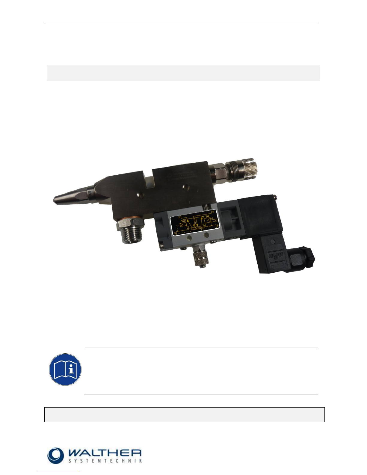
Assembly Instructions
Full-Jet Valve VMS-02
Article Number: V02-…
IMPORTANT
Please read this Assembly Instruction carefully before unpacking and start of operation with
the incomplete device, and make sure you follow it strictly!
The incomplete device will only be used, serviced or repaired by persons who are familiar
with the Assembly Instruction as well the guiding rules on work safety and accident
prevention.
Please keep this Translation of the „Original Assembly Instruction“ always close to the incomplete
device! The instructions have to be constantly available!

Rev. 1.4
Assembly Instructions – Full-Jet Valve VMS-02
Page 2 of 19
Walther Systemtechnik GmbH – D 76726 Germersheim
Telefon: +49 (0)7274-7022-0 Telefax: +49 (0)7274-7022-91
http://www.walther-2000.de – info@walther-2000.de
Table of Contents
Page
EC DECLARATION OF INCORPORATION ....................................................................................................................... 4
1 INTRODUCTION ................................................................................................................................................. 5
1.1 TARGET GROUP OF THE ASSEMBLY INSTRUCTIONS ............................................................................................................ 5
1.2 LIST OF SIGNS AND SYMBOLS ....................................................................................................................................... 5
2 SAFETY............................................................................................................................................................... 5
2.1 GENERAL INFORMATION ............................................................................................................................................. 5
2.2 DANGERS FROM RESIDUAL ENERGY ............................................................................................................................... 5
2.3 WARRANTY AND LIABILITY ........................................................................................................................................... 5
2.4 CORRECT USE ........................................................................................................................................................... 6
2.5 INCORRECT USE ........................................................................................................................................................ 6
2.6 QUALIFICATION OF PERSONNEL .................................................................................................................................... 6
3 TRANSPORT ....................................................................................................................................................... 7
3.1 PACKAGING .............................................................................................................................................................. 7
3.2 TASKS BEFORE TRANSPORT .......................................................................................................................................... 7
4 DESCRIPTION OF FUNCTION .............................................................................................................................. 7
4.1 DESIGNATED USE ....................................................................................................................................................... 7
4.2 TECHNICAL DATA ....................................................................................................................................................... 7
4.3 TYPE LABEL .............................................................................................................................................................. 7
5 INITIAL START-UP ............................................................................................................................................... 8
5.1 MOUNTING AND INSTALLATION .................................................................................................................................... 8
5.2 HOSE MOUNTING...................................................................................................................................................... 8
5.3 RASTER-NEEDLE SENSOR ............................................................................................................................................ 8
5.3.1 Wiring Diagram of Proximity Switch for Needle Sensor .............................................................................. 8
5.4 ADJUSTING THE INCOMPLETE DEVICE ............................................................................................................................ 8
6 OPERATION ....................................................................................................................................................... 9
6.1 GENERAL INFORMATION ............................................................................................................................................. 9
6.2 OPERATION INSTRUCTIONS / OPERATING CONDITIONS ...................................................................................................... 9
7 MAINTENANCE AND REPAIR ............................................................................................................................ 10
7.1 GENERAL INFORMATION ........................................................................................................................................... 10
7.2 CLEANING .............................................................................................................................................................. 10
7.3 REPLACING NEEDLE (POS. 5.0) AND NOZZLE (POS. 1.0) ................................................................................................. 10
7.4 REPLACING THE SEALING SCREW (POS. 4.0) ................................................................................................................. 10
7.5 INSERTING GASKETS AND O-RINGS ............................................................................................................................. 11
7.6 ROUTINE TASKS ....................................................................................................................................................... 11
7.7 SPARE PARTS .......................................................................................................................................................... 11
7.8 CUSTOMER SERVICE / SUPPORT .................................................................................................................................. 11
8 TROUBLESHOOTING ........................................................................................................................................ 12
8.1 GENERAL INFORMATION ........................................................................................................................................... 12
8.2 MALFUNCTION: NOZZLE NEEDLE DOES NOT OPEN .......................................................................................................... 12
9 TAKING OUT OF SERVICE ................................................................................................................................. 12
9.1 SHORT INTERRUPTION .............................................................................................................................................. 12
9.2 LONG-TERM INTERRUPTION ....................................................................................................................................... 12
9.3 SHUTDOWN OF DEVICE ............................................................................................................................................. 12
10 APPENDIX ........................................................................................................................................................ 13
10.1 DIMENSIONED DRAWING WITH LONG NOZZLE (LV-VERSION) ...................................................................................... 13
10.2 DIMENSIONED DRAWING WITH SHORT NOZZLE (KV-VERSION) .................................................................................... 13
10.2.1 Spare Part Drawing .............................................................................................................................. 14

Rev. 1.4
Assembly Instructions – Full-Jet Valve VMS-02
Page 3 of 19
Walther Systemtechnik GmbH – D 76726 Germersheim
Telefon: +49 (0)7274-7022-0 Telefax: +49 (0)7274-7022-91
http://www.walther-2000.de – info@walther-2000.de
10.2.2 Spare Part List....................................................................................................................................... 15
10.3 ARTICLE NUMBERS FOR NOZZLES, NOZZLE NEEDLES AND MAGNETIC VALVES .................................................................. 15
10.4 ACCESSORIES ..................................................................................................................................................... 18
10.4.1 Center hole for Centering sleeve 97320602 .......................................................................................... 18
10.4.2 Add-on Elements .................................................................................................................................. 19

Rev. 1.4
Assembly Instructions – Full-Jet Valve VMS-02
Page 4 of 19
Walther Systemtechnik GmbH – D 76726 Germersheim
Telefon: +49 (0)7274-7022-0 Telefax: +49 (0)7274-7022-91
http://www.walther-2000.de – info@walther-2000.de
EC Declaration of Incorporation
in accordance with EU Machinery Directive 2006/42/EU, dated 17 May 2006, Appendix II B
We herewith confirm that the below mentioned incomplete device meets the basic requirements for safety
and health as stated in EU Machinery Directive 2006/42/EU for its design and construction as well as for the
configuration released by us on the market. This machine component will not be operated before it has been
determined that the incomplete system where the machine component will be installed also meets the
requirements of the Directive (2006/42/EG.
Manufacturer
Walther Systemtechnik GmbH
Hockenheimer Straße 3
D- 76726 Germersheim
Description
VMS-02 Full-Jet Valve, Article No. V02-…
We also declare the conformity with other, product-relevant directives/guidelines:
Mach. Direct. 2006/42/EU App. I, Clause: 1.1.2, 1.1.3, 1.1.5, 1.1.6, 1.3.2, 1.3.3,
1.3.4, 1.5.1, 1.5.9
EMC- Directive 2014/30/EU, dated 26. February 2014
Applied harmonized standards, in particular:
DIN EN ISO 12100 Safety of Machinery – General Design Principles –
Risk Assessment and Risk Reduction (ISO
12100:2010)
In addition, we also confirm that the special documentation according to Appendix VII Part B has
been prepared.
The manufacturer, respectively his authorized representative obligates himself to submit this documentation
to the market surveillance authorities, if requested.
This EC Declaration of Incorporation becomes invalid if the incomplete device will be altered or changed
without consent of Walther Systemtechnik GmbH.
Authorized representative for Technical Documentation:
Stefan Hirl, Hockenheimer Straße 3, D- 76726 Germersheim
Germersheim, 23 October 2018
(Place, Date) (Stefan Hirl, Management)
Rev. 1.4
Assembly Instructions – Full-Jet Valve VMS-02
Page 5 of 19
Walther Systemtechnik GmbH – D 76726 Germersheim
Telefon: +49 (0)7274-7022-0 Telefax: +49 (0)7274-7022-91
http://www.walther-2000.de – info@walther-2000.de
1 Introduction
1.1 Target Group of the Assembly Instructions
Operating Personnel
Maintenance Personnel
1.2 List of Signs and Symbols
Symbols are used to identify hazards and certain practices. Symbols are also used in the assembly
instructions. The below symbols for hazards and information describe circumstances which can result in
damages to persons, objects and environment if not observed.
The following terms and symbols are used in the assembly instructions to identify hazards:
DANGER
Describes a potentially dangerous situation.
Death, grievous bodily harm or severe material damage WILL occur if the respective
measures of precaution have not been taken.
WARNING
Describes a potentially dangerous situation.
Death, grievous bodily harm or severe material damage MAY occur if the respective
measures of precaution have not been taken.
CAUTION
Describes a potentially dangerous situation.
Slight injuries CAN occur if the respective measures of precaution have not been taken.
This signal word is also used to describe possible property damages.
IMPORTANT
Indicates tips for usage and other particularly useful information.
No dangerous situation.
2 Safety
2.1 General Information
The construction of this incomplete device is according to the latest technology and is absolutely reliable.
The individual components as well as the complete device are continuously checked by our quality management.
2.2 Dangers from Residual Energy
Please instruct the operating personnel on the respective measures to be taken against the occurrence of
mechanical, hydraulic, pneumatic and electric / electronic residual energies.
2.3 Warranty and Liability
According to the conditions laid down by the German Engineering Federation (VDMA), Walther Systemtechnik GmbH has a guarantee of 12 months under normal European operating conditions on its own parts
(spare parts are excluded); or according to the conditions of the manufacturer.
This guarantee can only be granted by Walther Systemtechnik GmbH, if:
the user has thorough knowledge of the content of these assembly instructions;
the user follows the instructions and notes contained in these assembly instructions;
the user does not rebuild or make changes on parts of the (incomplete) device without prior consent
of WST Systemtechnik GmbH.

Rev. 1.4
Assembly Instructions – Full-Jet Valve VMS-02
Page 6 of 19
Walther Systemtechnik GmbH – D 76726 Germersheim
Telefon: +49 (0)7274-7022-0 Telefax: +49 (0)7274-7022-91
http://www.walther-2000.de – info@walther-2000.de
2.4 Correct Use
The VMS-02 full jet valve is a needle valve suitable for the processing of sprayable media in continuous as
well as intermittent use. It is not suitable for spraying aggressive fluids such as acids, alkaline solutions,
cleaning agents, chemicals etc. In case of doubt, please contact the manufacturer.
2.5 Incorrect Use
Operating the incomplete device with insufficient knowledge about the operation, maintenance and
care of the device.
Making changes, extensions or alterations on the incomplete device that may hamper its safety
without the prior consent of Walther Systemtechnik GmbH.
Operating the incomplete device with defective safety installations or not properly attached or mal-
functioning safety devices.
Using unsuitable materials.
Handling the incomplete device while energized
2.6 Qualification of Personnel
Only trained and instructed personnel will conduct work with or on the equipment.
The responsibilities of the personnel for assembly work, operation, repair work or maintenance work must be
clearly assigned to individuals!
Persons in training may work with the equipment only under supervision of an experienced person.
Personnel
Task
Instructed
Personnel
Personnel with Technical
Qualification
Specialist
Supervisor
Packaging, Transport
X
-
-
-
Commissioning
X
X
-
Operation
X
-
Troubleshooting, general
X
X
-
Troubleshooting
mechanical
-
X
-
-
Troubleshooting electrical
-
-
X
-
Setting up
-
X
-
-
Maintenance
-
X
-
-
Repair
-
X
X
-
Taking out of service,
Storage
-
X
X
-

Rev. 1.4
Assembly Instructions – Full-Jet Valve VMS-02
Page 7 of 19
Walther Systemtechnik GmbH – D 76726 Germersheim
Telefon: +49 (0)7274-7022-0 Telefax: +49 (0)7274-7022-91
http://www.walther-2000.de – info@walther-2000.de
3 Transport
3.1 Packaging
The type of packaging depends on the individual mode of shipping. If not separately contracted, the
packaging is in accordance with the rules and regulations of Walther Systemtechnik GmbH.
3.2 Tasks before Transport
The following has to be done before transport:
Disconnect all power lines.
The actual transport of the incomplete device and its individual parts requires special care in order to prevent
damages from external forceful impact or careless on- and off-loading. Depending on the mode of
transportation, suitable transport and load securing has to be selected. The incomplete device will be aligned
and leveled by appropriate fastening elements.
4 Description of Function
4.1 Designated Use
CAUTION
The use of other media can cause functional failures, material damages or even the
complete destruction of the device.
The full jet valves of the VMS-01 series are pneumatically controlled application devices that are perfect for
all applications with little space, such as installations in machines or robots due to their little weight and compact size. The employment of long nozzles facilitates a tilting of the devices towards each other, reducing the
space requirements to a minimum. The valves are preferably used for the application of sealants, adhesives
and oils. The needle piston is alternately impinged on by air, triggering an opening and closing of the needle.
If the control air is cut off or fails, the spring closes the needle. The medium is transported to the valve either
out of a pressure tank or a pump. The valve discharges a full jet. Depending on the nozzle size, media of
different viscosities can be processed.
4.2 Technical Data
General Data
Dimensions [mm] KV-version
ca. 144 x 15 x 82 (dimensioned drawing see Appendix!)
Dimensions [mm] LV-version
ca. 162 x 15 x 82 (dimensioned drawing see Appendix!)
Weight [g]
ca. 375
Sealing material
Viton
Energy Supply
Control air pressure [bar]
min. 6 (from 50 bar material pressure = 8 bar)
Material pressure [bar]
max. 100
4.3 Type Label
The type identification is etched in close to the material connection. The serial number is also inscribed in
this area.

Rev. 1.4
Assembly Instructions – Full-Jet Valve VMS-02
Page 8 of 19
Walther Systemtechnik GmbH – D 76726 Germersheim
Telefon: +49 (0)7274-7022-0 Telefax: +49 (0)7274-7022-91
http://www.walther-2000.de – info@walther-2000.de
5 Initial Start-up
5.1 Mounting and Installation
The valves can be installed in any position. The distance to the application are depends on the desired
application image.
Vibrations of the valve caused by fast intermitting cycles require solid and tight installation. The device
comes with two borings of 5mm diameter which have been designed for a solid mounting. Excessive machine vibrations to the valves should be avoided:
5.2 Hose Mounting
Two functional hoses will be connected as follows:
1. Control air (black) to M5-connection - Pos. 11.0 „control air“
3. Material (transparent) 1/4"-connection - Pos. 13.0 „material“
5.3 Raster-Needle Sensor
Optionally, you can use a raster-needle lock with a pre-installed, inductive proximity switch. It will release a
signal when the needle piston with the needle is open. This will help you in digitally monitoring the status
„nozzle open“.
5.3.1 Wiring Diagram of Proximity Switch for Needle Sensor
braun (1)
schwarz (4)
blau (3)
U
I
B
A
R
L
Last
+U
A
0V
B
10 ... 30 VDC
100 mA max.
The stroke must be open at least 10 raster steps, in order to guarantee correct functioning of the
proximity switch!
5.4 Adjusting the Incomplete Device
The amount of material can be regulated via the stroke adjustment of the needle (7.0). A left turn of the regulating knob increases the material amount. A fine precision thread affects a needle rise that results in an
adjustment of 0.5 mm with each turn of the adjusting knob.
IMPORTANT
Do not turn the regulating knob further to the left if no more stops are noticeable while turning it! The maximum fluid outlet has been reached!
Further turning will damage the regulating screw!
IMPORTANT
Nozzle and needle can be damaged by wrong handling. Only decrease the material flow (by
a right turn of the regulating knob) if material spills out. Do not turn the regulating knob further to the right after the nozzle is closed!

Rev. 1.4
Assembly Instructions – Full-Jet Valve VMS-02
Page 9 of 19
Walther Systemtechnik GmbH – D 76726 Germersheim
Telefon: +49 (0)7274-7022-0 Telefax: +49 (0)7274-7022-91
http://www.walther-2000.de – info@walther-2000.de
6 Operation
6.1 General Information
This device may only be operated if the safety-related equipment is permanently effective and not suspended during operation or altered in its intended effectiveness.
6.2 Operation Instructions / Operating Conditions
CAUTION
Never point the jet at people. The wearing of eye protection is strongly recommended. The
spraying process can create noise depending on the air and fluid pressures used. Ear protection should be worn, if required.
WARNING
Danger caused by flammable, harmful fluid. Always follow the safety instructions on the container or the safety data sheet for the fluid.
The VMS-02 full jet valve usually works with a control air pressure of 5-6 bar and material pressures of up to
30 bar. In case high material pressures are necessary, the safety regulations of the trade association must
always be observed.
The valves are suitable for contactless and regular application and can be controlled for intermittent or continuous use. According to the individual application, the control air must be adjusted to the operating cycles
and to the higher or lower material pressures. 40 tacts per second can be reached under appropriate operating conditions (material pressure, control air pressure, needle stroke, and short conductions).
The amount of material can be regulated via the stroke adjustment of the needle. A left turn of the regulating
knob increases the material amount. A fine precision thread affects a needle rise that results in an
adjustment of 0.5 mm with each turn of the adjusting knob.
IMPORTANT
A plant-specific setting is required for an optimal adjustment of the application pattern.
Starting values from laboratory tests can be used as a basis. However, these may need to
be adjusted for the specific plant. A combination of the following parameters is necessary:
nozzle size, opening time, opening stroke, material pressure and temperature (if applicable.
It is harmless to leave fluid in the valve during longer standstills if system stays under pressure (no
connection to outside air.

Rev. 1.4
Assembly Instructions – Full-Jet Valve VMS-02
Page 10 of 19
Walther Systemtechnik GmbH – D 76726 Germersheim
Telefon: +49 (0)7274-7022-0 Telefax: +49 (0)7274-7022-91
http://www.walther-2000.de – info@walther-2000.de
7 Maintenance and Repair
7.1 General Information
CAUTION
Before starting any maintenance or repair work, ensure that all air-operated tools are
depressurized and disconnected from the air supply.
Before opening the spray valve it must be disconnected from the air and fluid supply.
Otherwise, ejected components can cause injuries.
The full jet valves of the VMS-02 series are high-quality precision devices which will not fail if treated
correctly and will operate almost maintenance-free. Always keep clean and observe minimum instructions to
maintain a long life of the valve. Always use clean and filtered material only. The control air must also be
clean and should be slightly oiled, if necessary. Maintenance also depends on the individual operating
conditions and the type of media used.
7.2 Cleaning
IMPORTANT
Only use soft brushes for outside cleaning of the nozzle tips. Never use metal tools with
sharp edges.
Wash equipment thoroughly after use to remove residues and dirt, especially if needle (5) or sealing screw
(4) or nozzle (1) has to be exchanged.
7.3 Replacing Needle (Pos. 5.0) and Nozzle (Pos. 1.0)
CAUTION
First depressurize all connections.
Completely unscrew raster needle lock (pos. 7.0). Unscrew nozzle (pos. 1.0). Take out the needle spring
(pos. 6.0) and carefully press out needle (pos. 5.0) from the nozzle side. Grease new parts slightly and
reassemble them in reverse order. We do not recommend reusing old needles. Piercing of slightly dirty
needles through the form gasket (pos. 3.3) can cause leakages.
7.4 Replacing the Sealing Screw (Pos. 4.0)
Completely unscrew raster needle lock (pos. 7.0) and nozzle (pos. 1.0). Carefully push out the needle (pos.
5.0) towards the nozzle end. Then unscrew the sealing screw (pos. 4.0) from the thread with a screwdriver.
Since the outer O-ring (pos. 3.1) prevents the sealing screw from falling through the mounting thread of the
valve body (pos. 2.0), it is necessary to push the sealing screw together with O-ring (3.1) carefully backwards through the thread using a thin strip of metal (0.5 – 1.0 mm) which you push between the recess in the
body and flat in front of the front end of the sealing screw. You can then take the sealing screw out of the
enclosure.

Rev. 1.4
Assembly Instructions – Full-Jet Valve VMS-02
Page 11 of 19
Walther Systemtechnik GmbH – D 76726 Germersheim
Telefon: +49 (0)7274-7022-0 Telefax: +49 (0)7274-7022-91
http://www.walther-2000.de – info@walther-2000.de
7.5 Inserting Gaskets and O-Rings
IMPORTANT
Gaskets and sealing kits can be damaged. Do not use any sharp-edged metal tools for removing or inserting gaskets!
If a complete sealing screw (pos. 4.0) with an inserted gasket set (pos. 3.0) is not available as a
replacement, the old gaskets must be removed and replaced with new ones. In order to do so, the sealing
screw must be thoroughly cleaned so that no particles of the previous spraying fluid impair the installation of
the new gaskets. The O-ring seats should be lightly greased with a lubricant (technical Vaseline). First insert
O-ring (pos. 4.2) into the rear hole of the sealing screw until it reaches the end. Then insert O-ring (pos. 3.1)
into the outermost groove. Insert the special form gasket (pos. 3.3) into the front seat. Since this form gasket
is not symmetrical, the side with the larger outer diameter must be inserted facing forwards, i.e. it must point
in the direction of the nozzle after the complete sealing screw has been installed. Slightly grease the sealing
screw (pos. 4.0) and insert it back into the valve body (pos. 2.0). Use a screwdriver to carefully push it
through the mounting thread together with the outer O-ring (pos. 3.1) without twisting it. Then screw the
sealing screw into the thread (gently tighten).
Do not use any metallic or sharp-edged aids or tools when you insert the O-rings and the special form
gasket. Despite all its outstanding sealing qualities, the special form gasket is a sensitive precision
component, which cannot tolerate impacts or pressure.
7.6 Routine Tasks
No.
Description
Cleaning
Lubricating
Inspecting
Additional tasks
Frequency
1.
connections
(tightness)
X
monthly
2.
nozzle
X X
exchange if
damaged
monthly
3.
complete valve
X
check for wear
after 10 mio.
switching
operations
7.7 Spare Parts
IMPORTANT
Only use original spare parts from the manufacturer!
Wrong or defective spare parts from other manufacturers can damage the device. If other
than original spare parts of the manufacturer will be used, all obligations from the manufacturer or his sales partners, such as guarantees, service contracts etc will be forfeited without
further notice.
7.8 Customer Service / Support
Walther Systemtechnik GmbH
Hockenheimer Straße 3
D-76726 Germersheim
Deutschland
Telefon ++49(0)7274-7022-0
Telefax ++49(0)7274-7022-91
Email info@walther-2000.de
Internet www.walther-2000.de

Rev. 1.4
Assembly Instructions – Full-Jet Valve VMS-02
Page 12 of 19
Walther Systemtechnik GmbH – D 76726 Germersheim
Telefon: +49 (0)7274-7022-0 Telefax: +49 (0)7274-7022-91
http://www.walther-2000.de – info@walther-2000.de
8 Troubleshooting
8.1 General Information
IMPORTANT
First check all supply lines for proper connection and serviceability.
In case of serious problems that cannot be resolved, please contact the Walther Systemtechnik GmbH customer service.
8.2 Malfunction: Nozzle Needle does not open
Check if enough control air is available (5 - 6 bar).
Check if O-Rings (Pos. 4.2 or Pos. 5.1) are defective.
Check if needle (Pos.5.0) is sticky within the needle sealing (Pos.4.0).
Check if needle stroke is correctly set.
9 Taking out of Service
9.1 Short Interruption
A short interruption (15 min or more) has to be followed by a fine spraying.
IMPORTANT
Please follow the Operating Manual!
9.2 Long-term Interruption
The following has to be observed for a long-term interruption of the device/machine:
Depressurize material supply lines
Take off nozzle and clean with a special thinner and a soft cloth. Make sure that no cloth fibers are left
on the nozzle tip.
IMPORTANT
Please follow the maintenance guidelines!
9.3 Shutdown of Device
The following is important for a shutdown of the machine / device:
Clean-spray full jet valve with a special thinner.
IMPORTANT
Please follow the maintenance guidelines!

Rev. 1.4
Assembly Instructions – Full-Jet Valve VMS-02
Page 13 of 19
Walther Systemtechnik GmbH – D 76726 Germersheim
Telefon: +49 (0)7274-7022-0 Telefax: +49 (0)7274-7022-91
http://www.walther-2000.de – info@walther-2000.de
10 Appendix
10.1 Dimensioned Drawing with long Nozzle (LV-Version)
10.2 Dimensioned Drawing with short Nozzle (KV-Version)
ca . 16 2
40
1830
17
t= 1 5 m m
ca .82
M5
7. 5
ca . 1 4 4
1830
17
7. 5
ca . 8 2
22
M5
t= 15m m

Rev. 1.4
Assembly Instructions – Full-Jet Valve VMS-02
Page 14 of 19
Walther Systemtechnik GmbH – D 76726 Germersheim
Telefon: +49 (0)7274-7022-0 Telefax: +49 (0)7274-7022-91
http://www.walther-2000.de – info@walther-2000.de
10.2.1 Spare Part Drawing
12.0
13.0
11.0
9.0
10.0
8.0
2.0
1.0
3.3
3.1
4.1
4.2
5.0
5.1
6.0
7.2
7.4
7.5
3.2
7.1
7.3
7.0
Raster needle lock
„Standard“
7.0
Raster needle lock
„Needle sensor
24 VDC“

Rev. 1.4
Assembly Instructions – Full-Jet Valve VMS-02
Page 15 of 19
Walther Systemtechnik GmbH – D 76726 Germersheim
Telefon: +49 (0)7274-7022-0 Telefax: +49 (0)7274-7022-91
http://www.walther-2000.de – info@walther-2000.de
10.2.2 Spare Part List
Dwg-No. Article No. Qty Description
1.0 * 1 nozzle, stainless steel
2.0 97510064 1 valve body VMS-02, complete
3.0 97640102 1 gasket set
3.1 97640021 1 O-ring 6.07 x 1.78 mm / Viton
3.2 97640101 1
protecting cover, ø 10 x 6mm
3.3 97640004 1 Variseal 2.65 x 2.0 x 2.8 mm
4.0 97810014 1 sealing screw, complete, 11 x 21 mm
4.1 97810017 1 sealing screw, 11 x 21 mm
4.2 97640026 1 O-ring 2.90 x 1.78 mm
5.0 * 1 needle, complete
5.1 97640001 1 O-ring 7.65 x 1.78 mm / Viton
6.0 97820020 1 pressure spring 1.1 x 22 mm (0 - 30 bar material pressure)
6.0 97820024 1 pressure spring 1.2 x 21.5 mm (30 - 100 bar material pressure)
7.0 * 1 ratchet needle lock, ø 15 x 45 mm
8.0 97640077 2 O-ring 5 x 1 / Viton
9.0 97610004 2 screw M2.5 x 30
10.0 * 1 solenoid valve with plug
11.0 97220089 1 screw connection, complete, SW 8 x 19 mm
IMPORTANT
If a Luer-Lock adapter has been installed, we will mount nozzle needle (Article No.
97110235) as standard!
7.0
Raster needle lock
Article-No.
Description
97900008
“Standard“ raster needle lock
97900040
“Needle sensor 24 VDC“ raster needle lock
IMPORTANT
Please always indicate the inscribed serial numbers when ordering spare parts!
10.3 Article Numbers for Nozzles, Nozzle Needles and Magnetic Valves
1.0
Nozzle, LV, stainless steel
Artikel-Nr.
Description
97210132
Nozzle, LV, 0.2mm
97210133
Nozzle, LV, 0.3mm
97210134
Nozzle, LV, 0.4mm
97210102
Nozzle, LV, 0.5mm
97210136
Nozzle, LV, 0.6mm
97210137
Nozzle, LV, 0.7mm
97210138
Nozzle, LV, 0.8mm
97210139
Nozzle, LV, 1.0mm
97210140
Nozzle, LV, 1.2mm
97210141
Nozzle, LV, 1.5mm
97210142
Nozzle, LV, 2,0mm
97210481
Nozzle, LV, 2.5mm

Rev. 1.4
Assembly Instructions – Full-Jet Valve VMS-02
Page 16 of 19
Walther Systemtechnik GmbH – D 76726 Germersheim
Telefon: +49 (0)7274-7022-0 Telefax: +49 (0)7274-7022-91
http://www.walther-2000.de – info@walther-2000.de
1.0
Nozzle, KV, stainless steel
Artikel-Nr.
Description
97210143
Nozzle, KV, 0.2mm
97210144
Nozzle, KV, 0.3mm
97210145
Nozzle, KV, 0.4mm
97210146
Nozzle, KV, 0.5mm
97210147
Nozzle, KV, 0.6mm
97210148
Nozzle, KV, 0.7mm
97210149
Nozzle, KV, 0.8mm
97210150
Nozzle, KV, 1.0mm
97210151
Nozzle, KV, 1.2mm
97210152
Nozzle, KV, 1.5mm
97210153
Nozzle, KV, 2.0mm
1.0
Nozzle, LVP, stainless steel
Artikel-Nr.
Description
97210177
Nozzle, LVP, 0.3mm
97210178
Nozzle, LVP, 0.4mm
97210179
Nozzle, LVP, 0.5mm
97210180
Nozzle, LVP, 0.6mm
97210181
Nozzle, LVP, 0.8mm
97210182
Nozzle, LVP, 1.0mm
97210183
Nozzle, LVP, 1.2mm
1
Adapter Nozzles „Standard“ (length 31mm; IG G
1/8)
Artikel-Nr.
Description
97211587
Adapter Nozzle 0.3 mm
97211372
Adapter Nozzle 0.5 mm
97210984
Adapter Nozzle 1.0 mm
97211539
Adapter Nozzle 1.5 mm
97211617
Adapter Nozzle 2.0 mm
1
Adapter Nozzles „Luerlock“ (M12 x 0,75), cpl.
Artikel-Nr.
Description
97211915
Adapter Nozzle 0.2 mm
97211851
Adapter Nozzle 0.3 mm
97211997
Adapter Nozzle 0.5 mm
97211554
Adapter Nozzle 1.0 mm
97211909
Adapter Nozzle 1.5 mm
97212351
Adapter Nozzle 2.0 mm

Rev. 1.4
Assembly Instructions – Full-Jet Valve VMS-02
Page 17 of 19
Walther Systemtechnik GmbH – D 76726 Germersheim
Telefon: +49 (0)7274-7022-0 Telefax: +49 (0)7274-7022-91
http://www.walther-2000.de – info@walther-2000.de
5.0
Nozzle Needle complete, LV / LVP, carbide
Artikel-Nr.
Description
97110222
Needle, LV, 0.4mm for nozzle 0.2mm
97110223
Needle, LV, 0.5mm for nozzle 0.3mm
97110224
Needle, LV, 0.6/0.7mm for nozzle 0.4mm
97110225
Needle, LV, 0.8/1.0mm for nozzle 0.5/0.6/0.7mm
97110349
Needle, LV, 1.0mm for nozzle 0.8mm
97110227
Needle, LV, 1.2mm for nozzle 1.0mm
97110228
Needle, LV, 1.5mm for nozzle 1.2mm
97110229
Needle, LV, 2.0mm for nozzle 1.5/2.0/2.5mm
5.0
Nozzle Needle complete, KV, and und 1/8“ Adapter,
carbide
Artikel-Nr.
Description
97110231
Needle, KV, 0.4mm for nozzle 0.2mm
97110232
Needle, KV, 0.5mm for nozzle 0.3mm
97110233
Needle, KV, 0.6/0.7mm for nozzle 0.4mm
97110234
Needle, KV, 0.8/1.0mm for nozzle 0.5/0.6/0.7mm
97110347
Needle, KV, 1.0mm for nozzle 0.8mm
97110235
Needle, KV, 1.2mm for nozzle 1.0mm and all
Adapter Nozzles „Luerlock“
97110236
Needle, KV, 1.5mm for nozzle 1.2mm
97110237
Needle, KV, 2.0mm for nozzle 1.5/2.0mm
10.0
5/2-way Magnet Valve
Artikel-Nr.
Description
97150012
Magnetic valve 24V / DC / 1.6W
97150021
Magnetic valve 220V / 50Hz / 1.5W
Qty
Article No.
Description
1
979593
Gasket set Viton
1
979486
Gasket set Isolast

Rev. 1.4
Assembly Instructions – Full-Jet Valve VMS-02
Page 18 of 19
Walther Systemtechnik GmbH – D 76726 Germersheim
Telefon: +49 (0)7274-7022-0 Telefax: +49 (0)7274-7022-91
http://www.walther-2000.de – info@walther-2000.de
10.4 Accessories
Picture
Article Number
Description
979444
Cleaning set
(see also Product catalog ACCESSORIES)
97320602
Centering sleeve for an exact positioning of the valve
HZP-90-25W-07
Heating plate
10.4.1 Center hole for Centering sleeve 97320602
WICHTIG
If a Centering sleeve is retrofitted to an existing valve, the valve must be returned to us for
retrofitting of Center hole.

Rev. 1.4
Assembly Instructions – Full-Jet Valve VMS-02
Page 19 of 19
Walther Systemtechnik GmbH – D 76726 Germersheim
Telefon: +49 (0)7274-7022-0 Telefax: +49 (0)7274-7022-91
http://www.walther-2000.de – info@walther-2000.de
10.4.2 Add-on Elements
Needle Sensor
The installation of a sensor for the raster needle is factory-made. It is integrated in the raster needle lock
(pos. 7.0 of spare parts list). As a spare part, the raster needle lock is always delivered as a complete unit,
since the initiator is factory-adjusted and pasted in.
Pos.
Description
1
Raster needle sensor
Pressure sensor
The attachment of a pressure sensor is also factory-made. Its position can optionally be on the side (left /
right) or on top. For additional information please refer to the Operating Manual “Pressure Sensors 97PA-
21x-xxx“.
Pos.
Description
2
Pressure sensor mounted on the left of the pulse valve
3
Pressure sensor mounted on top of the pulse valve
4
Pressure sensor mounted on the right side of the pulse valve
Hotplate
The installation of a heating plate is also factory-made. Its position can optionally be on the left or on the right
side. For further information please refer to the Description “Heating and Accessories.
Pos.
Description
5
Hotplate mounted on the left side of the pulse valve
6
Hotplate mounted on the right side of the pulse valve
 Loading...