

Rev. 1.3
Assembly Instructions - Spray Valve SMS-22
Page 1 of 25
Walther Systemtechnik GmbH – D 76726 Germersheim
Telefon: +49 (0)7274-7022-0 Telefax: +49 (0)7274-7022-91
http://www.walther-2000.de – info@walther-2000.de
NOTE
Please read the Assembly Instructions carefully before first using the incomplete device and
strictly adhere to the instructions!
The incomplete device may only be worked with and worked on by persons who are familiar
with the assembly instructions and the current regulations for industrial safety and accident
prevention.
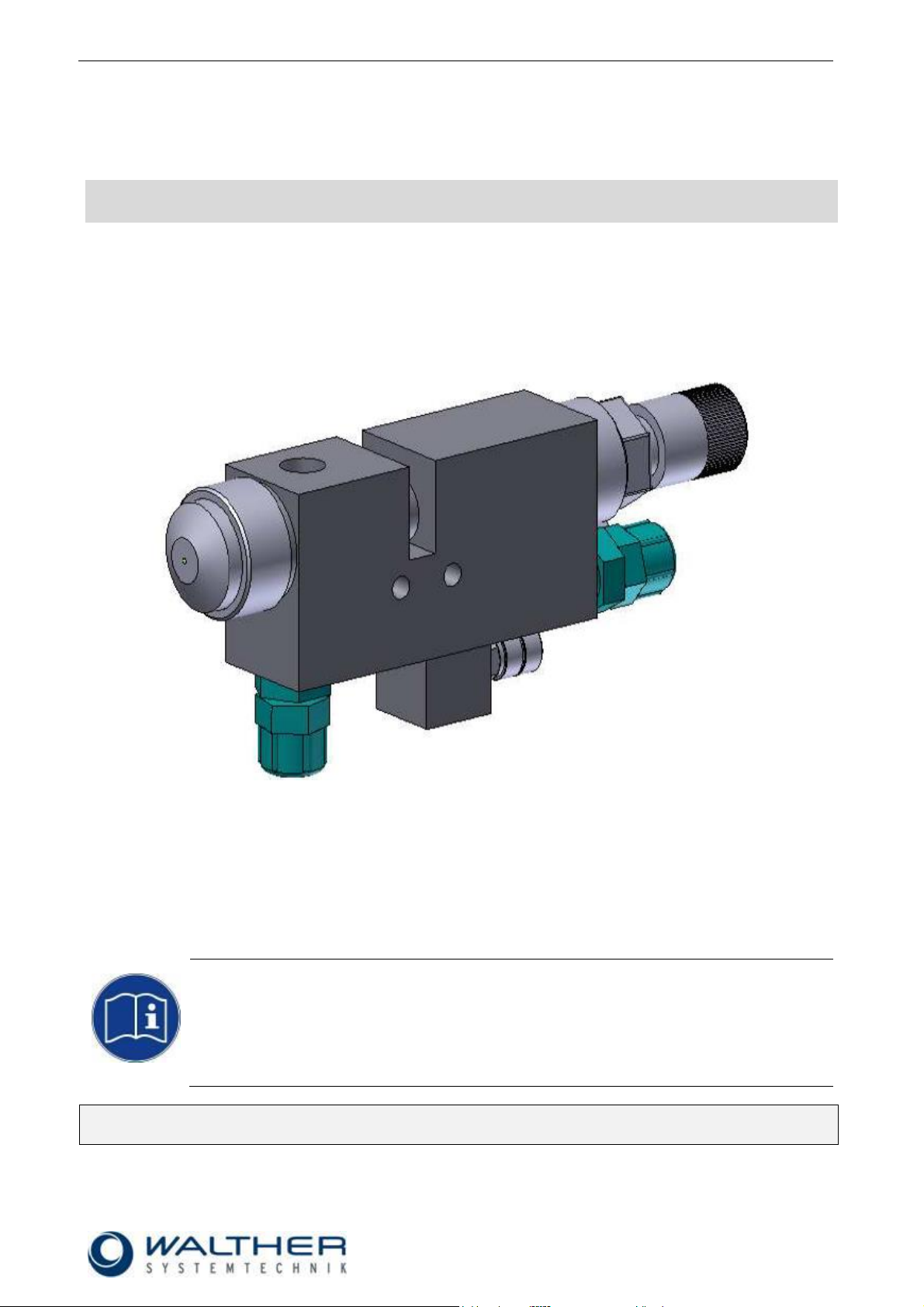
Assembly Instructions
Spray Valve SMS-22
Article Number: S22-….
Keep a translated version of the original Assembly Instructions a safe place close to the device!
The instructions must be available at all times!

Rev. 1.3
Assembly Instructions - Spray Valve SMS-22
Page 2 of 25
Walther Systemtechnik GmbH – D 76726 Germersheim
Telefon: +49 (0)7274-7022-0 Telefax: +49 (0)7274-7022-91
http://www.walther-2000.de – info@walther-2000.de
Table of Contents
Page
EC DECLARATION OF INCORPORATION ....................................................................................................................... 4
1 INTRODUCTION ................................................................................................................................................. 5
1.1 TARGET GROUP OF THE ASSEMBLY INSTRUCTIONS ............................................................................................................ 5
1.2 LIST OF SIGNS AND SYMBOLS ....................................................................................................................................... 5
2 SAFETY............................................................................................................................................................... 5
2.1 GENERAL INFORMATION ............................................................................................................................................. 5
2.2 DANGERS FROM RESIDUAL ENERGY ............................................................................................................................... 5
2.3 WARRANTY AND LIABILITY ........................................................................................................................................... 5
2.4 CORRECT USE ........................................................................................................................................................... 6
2.5 INCORRECT USE ........................................................................................................................................................ 6
2.6 QUALIFICATION OF PERSONNEL .................................................................................................................................... 6
3 TRANSPORT ....................................................................................................................................................... 6
3.1 PACKAGING .............................................................................................................................................................. 6
3.2 TASKS BEFORE TRANSPORT .......................................................................................................................................... 6
4 DESCRIPTION OF FUNCTION .............................................................................................................................. 7
4.1 PURPOSE OF THE DEVICE ............................................................................................................................................. 7
4.2 TECHNICAL DATA ....................................................................................................................................................... 7
4.3 TYPE LABEL .............................................................................................................................................................. 7
5 MOUNTING AND FIRST START-UP ...................................................................................................................... 8
5.1 HOSE MOUNTING...................................................................................................................................................... 8
5.2 TOTAL VIEW / DESCRIPTION ......................................................................................................................................... 9
5.3 WIRING LAYOUT (SEPARATE CONTROL UNIT) ................................................................................................................... 9
5.4 ADJUSTING THE DEVICE ............................................................................................................................................ 10
6 OPERATION ..................................................................................................................................................... 10
6.1 GENERAL INFORMATION ........................................................................................................................................... 10
6.2 OPERATION INSTRUCTIONS / OPERATING CONDITIONS .................................................................................................... 10
6.3 OPERATING ELEMENTS ............................................................................................................................................. 11
7 TAKING OUT OF SERVICE ................................................................................................................................. 11
7.1 SHORT INTERRUPTION .............................................................................................................................................. 11
7.2 LONG-TERM INTERRUPTION ....................................................................................................................................... 11
7.3 SHUTDOWN OF DEVICE ............................................................................................................................................. 11
8 MAINTENANCE AND REPAIR ............................................................................................................................ 12
8.1 GENERAL INFORMATION ........................................................................................................................................... 12
8.2 CLEANING .............................................................................................................................................................. 12
8.3 REPLACING THE NOZZLE AND NOZZLE NEEDLE ............................................................................................................... 12
8.4 REPLACING THE SEALING SCREW ................................................................................................................................ 13
8.5 REPLACING THE SEALING ELEMENTS OF THE SEALING SCREW ........................................................................................... 13
8.6 SPARE PARTS .......................................................................................................................................................... 14
8.7 CUSTOMER SERVICE / SUPPORT .................................................................................................................................. 14
9 TROUBLESHOOTING ........................................................................................................................................ 14
9.1 GENERAL INFORMATION ........................................................................................................................................... 14
9.2 MALFUNCTIONS: ..................................................................................................................................................... 14
9.3 SPRAY IMAGES / ERRORS ........................................................................................................................................... 15
10 APPENDIX ........................................................................................................................................................ 16
10.1 DIMENSIONED DRAWING SMS-22 ........................................................................................................................ 16
10.1.1 Spare Part Drawing SMS-22 ................................................................................................................. 17
10.1.2 Spare Part List for SMS-22 (Standard) .................................................................................................. 18

Rev. 1.3
Assembly Instructions - Spray Valve SMS-22
Page 3 of 25
Walther Systemtechnik GmbH – D 76726 Germersheim
Telefon: +49 (0)7274-7022-0 Telefax: +49 (0)7274-7022-91
http://www.walther-2000.de – info@walther-2000.de
10.2 ARTICLE NUMBER FOR AIR CAPS ............................................................................................................................ 19
10.3 ARTICLE NUMBERS FOR NOZZLES .......................................................................................................................... 20
10.4 ARTICLE NUMBERS FOR NOZZLE NEEDLES ................................................................................................................ 21
10.5 WEAR-AND-TEAR PARTS KITS ................................................................................................................................ 22
10.6 ACCESSORIES ..................................................................................................................................................... 23
10.6.1 Center hole for Centering sleeve 97320602 .......................................................................................... 24
10.6.2 Add-on Elements .................................................................................................................................. 25

Rev. 1.3
Assembly Instructions - Spray Valve SMS-22
Page 4 of 25
Walther Systemtechnik GmbH – D 76726 Germersheim
Telefon: +49 (0)7274-7022-0 Telefax: +49 (0)7274-7022-91
http://www.walther-2000.de – info@walther-2000.de
EC Declaration of Incorporation
in accordance with EU Machinery Directive 2006/42/EU, dated 17 May 2006, Appendix II B
We herewith confirm that the below mentioned incomplete device meets the basic requirements for safety
and health as stated in EU Machinery Directive 2006/42/EU for its design and construction as well as for the
configuration released by us on the market. This machine component will not be operated before it has been
determined that the incomplete system where the machine component will be installed also meets the
requirements of the Directive (2006/42/EG).
Manufacturer
Walther Systemtechnik GmbH
Hockenheimer Straße 3
D- 76726 Germersheim
Description
Spray Valve SMS-22, Article No. S22-…
We also declare the conformity with other, product-relevant directives/guidelines:
Mach. Direct. 2006/42/EU App. I, Clause: 1.1.2, 1.1.3, 1.1.5, 1.1.6, 1.3.2, 1.3.3,
1.3.4, 1.5.8, 1.5.9
EMC- Directive 2014/30/EU, dated 26. February 2014
Applied harmonized standards, in particular:
DIN EN ISO 12100 Safety of Machinery – General Design Principles –
Risk Assessment and Risk Reduction (ISO
12100:2010)
In addition, we also confirm that the special documentation according to Appendix VII Part B has
been prepared.
The manufacturer, respectively his authorized representative obligates himself to submit this documentation
to the market surveillance authorities, if requested.
This EC Declaration of Incorporation becomes invalid if the incomplete device will be altered or changed
without consent of Walther Systemtechnik GmbH.
Authorized representative for Technical Documentation:
Stefan Hirl, Hockenheimer Straße 3, D- 76726 Germersheim
Germersheim, 19 April 2018
(Place, Date) (Stefan Hirl, Management)
Rev. 1.3
Assembly Instructions - Spray Valve SMS-22
Page 5 of 25
Walther Systemtechnik GmbH – D 76726 Germersheim
Telefon: +49 (0)7274-7022-0 Telefax: +49 (0)7274-7022-91
http://www.walther-2000.de – info@walther-2000.de
DANGER
Describes a potentially dangerous situation.
Death, grievous bodily harm or severe material damage WILL occur if the respective
measures of precaution have not been taken
WARNING
Describes a potentially dangerous situation.
Death, grievous bodily harm or severe material damage MAY occur if the respective
measures of precaution have not been taken.
CAUTION
Describes a potentially dangerous situation.
Slight injuries CAN occur if the respective measures of precaution have not been taken. This
signal word is also used to describe possible property damages.
IMPORTANT
Indicates tips for usage and other particularly useful information.
No dangerous situation.
1 Introduction
1.1 Target Group of the Assembly Instructions
Operating Personnel
Maintenance Personnel
1.2 List of Signs and Symbols
The assembly instructions warn users of operations which may put their health at risk.
The warnings are indicated by combinations of text and symbols as follows:
2 Safety
2.1 General Information
The construction of this device is according to the latest technology and is absolutely reliable. The individual
components as well as the complete device are continuously checked by our quality management.
2.2 Dangers from Residual Energy
Please instruct the operating personnel on the respective measures to be taken against the occurrence of
mechanical, hydraulic, pneumatic and electric / electronic residual energies.
2.3 Warranty and Liability
According to the conditions laid down by the German Engineering Association (VDMA), Walther Systemtechnik GmbH has a guarantee of 12 months under normal European operating conditions on its own
parts (spare parts are excluded); or according to the conditions of the manufacturer.
This guarantee can only be granted by Walther Systemtechnik GmbH, if:
the user has thorough knowledge of the content of the assembly instructions;
the user follows the instructions and notes contained in the assembly instructions;
the user does not rebuild or make changes on parts of the device without prior consent of WST Sys-
temtechnik GmbH.
Rev. 1.3
Assembly Instructions - Spray Valve SMS-22
Page 6 of 25
Walther Systemtechnik GmbH – D 76726 Germersheim
Telefon: +49 (0)7274-7022-0 Telefax: +49 (0)7274-7022-91
http://www.walther-2000.de – info@walther-2000.de
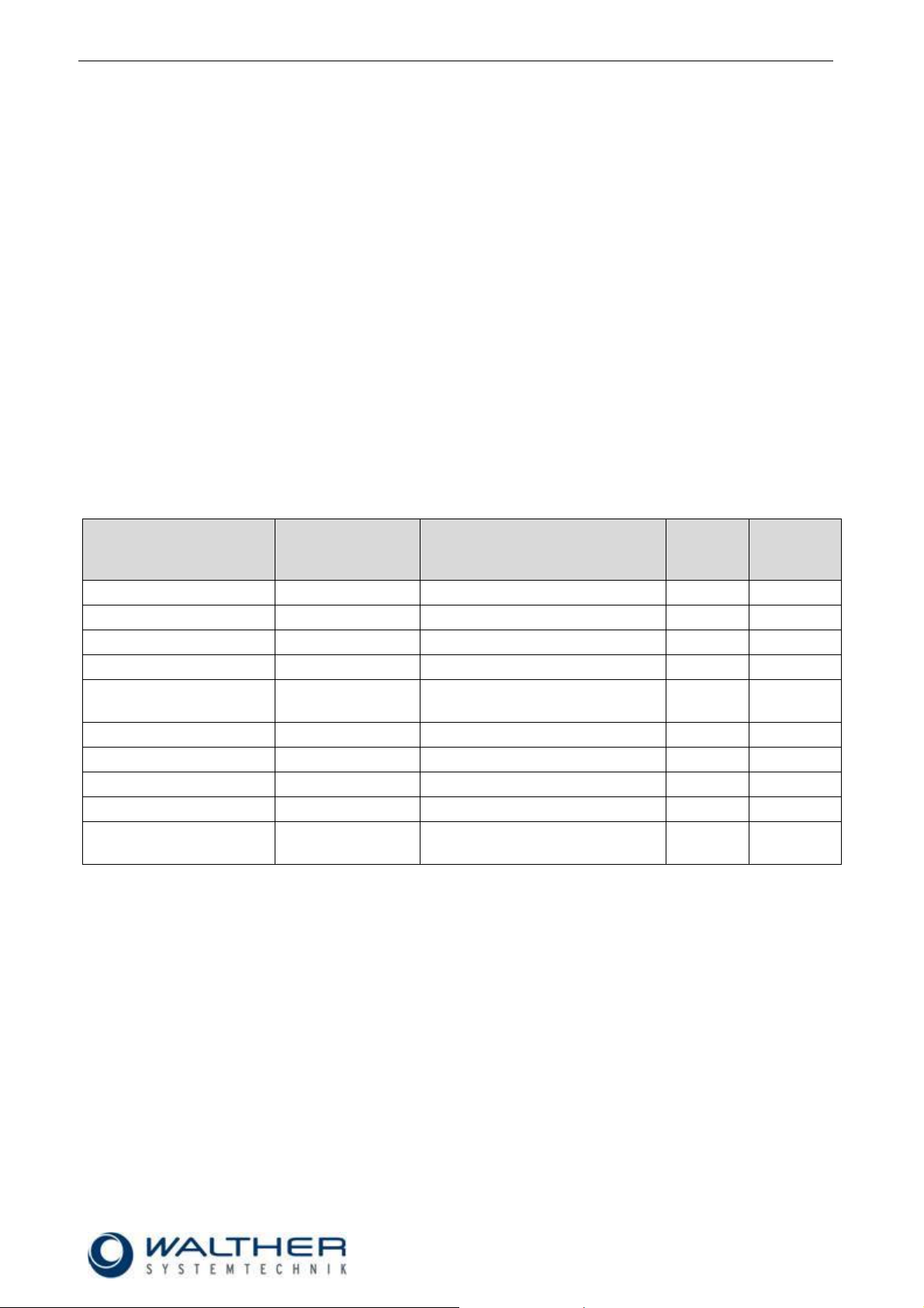
Personnel
Task
Instructed
Personnel
Personnel with Technical
Qualification
Specialist
Supervisor
Packaging, Transport
X
-
-
-
Commissioning
X
X
-
Operation
X
-
Troubleshooting, general
X
X
-
Troubleshooting
mechanical
-
X
-
-
Troubleshooting electrical
-
-
X
-
Setting up
-
X
-
-
Maintenance
-
X
-
-
Repair
-
X
X
-
Taking out of service,
Storage
-
X
X
-
2.4 Correct Use
This device is a needle valve and will be used for processing materials which can be sprayed in continuous
or intermitting operation. Under no circumstances shall aggressive media such as acids, alkaline solutions,
detergents, chemicals or others be sprayed. If you are not sure, please contact the manufacturer if a certain
spray medium is suitable for this device.
2.5 Incorrect Use
Operating the device with insufficient knowledge about the operation, maintenance and care of the de-
vice.
Making changes, extensions or alterations on the device that may hamper its safety without the prior
consent of Walther Systemtechnik GmbH.
Operating the device with defective safety installations or not properly attached or malfunctioning safety
devices.
Using unsuitable materials.
Handling the device while energized
2.6 Qualification of Personnel
Only trained and instructed personnel may conduct work on the equipment.
The responsibilities of the personnel for assembly work, operation, repair work or maintenance work must be
clearly assigned to individuals!
Persons in training may work with the equipment only under supervision of an experienced person.
3 Transport
3.1 Packaging
The type of packaging depends on the individual mode of shipping. If not separately contracted, the
packaging is in accordance with the rules and regulations of Walther Systemtechnik GmbH. This rule is in
accordance with the Federal Association for Packaging HPE.
3.2 Tasks before Transport
The following has to be done before transport:
Disconnect all power lines.
The actual transport of the incomplete device and its individual parts requires special care in order to prevent
damages from external forceful impact or careless on- and off-loading. Depending on the mode of
transportation, suitable transport and load securing has to be selected. The incomplete device will be aligned
and leveled by appropriate fastening elements.

Rev. 1.3
Assembly Instructions - Spray Valve SMS-22
Page 7 of 25
Walther Systemtechnik GmbH – D 76726 Germersheim
Telefon: +49 (0)7274-7022-0 Telefax: +49 (0)7274-7022-91
http://www.walther-2000.de – info@walther-2000.de
CAUTION
The use of other media can cause functional failures, damages or even the destruction of the
device.
Size with Flat-jet air cap [mm]
ca. 131 x 58 x 24
Size with Round-jet air cap [mm]
ca. 127 x 58 x 24
Weight [g]
Frequency (per second)
ca. 500
max. 30 (see note under 6.2)
Control air pressure [bar]
5-6
Atomizer air pressure [bar]
max. Control air pressure - 0,5 bar
Material pressure [bar]
max. 35
Temperature [°C]
max. 80
The type label was etched into the casing near the
material connection. The serial number is also
hammered into this label.
4 Description of Function
The automatic spray valves of the SMS-22 series are pneumatically controlled and are suitable for the finest
application of liquid up to pasty media, such as adherents, oils or greases or colors. The spraying process is
produced through the control air, the material supply pressure and the atomizer air; and it can be either intermittent or continuous. Depending on the selected air cap, a flat jet or a round jet will be produced. The
needle function is: open through air pressure / close through air pressure.
4.1 Purpose of the Device
Control air will be supplied to the spraying device via a 5/2-way pilot valve (not included in delivery); when in
basic position it has a passage for closing the needle. If the pilot valve receives a signal, the front area of the
needle piston will be filled with air which causes the needle piston to push back the spring, and the needle
opens.
The medium can now escape from the nozzle. When the signal on the pilot valve stops, the spray valve will
be closed (needle will be pushed into the nozzle).
The atomizer air divides the material into a spray jet and can be controlled through a 3/2-way magnetic valve
(not included in delivery). A short pre- or post-spraying can also be required. And a suitable device has to be
employed for pressure control.
When the control air is turned off or fails, the needle spring will close the spraying device.
The medium itself is supplied to the valve from a pressured container or via a pump.
4.2 Technical Data
General Data
Energy Supply
4.3 Type Label
.
Rev. 1.3
Assembly Instructions - Spray Valve SMS-22
Page 8 of 25
Walther Systemtechnik GmbH – D 76726 Germersheim
Telefon: +49 (0)7274-7022-0 Telefax: +49 (0)7274-7022-91
http://www.walther-2000.de – info@walther-2000.de
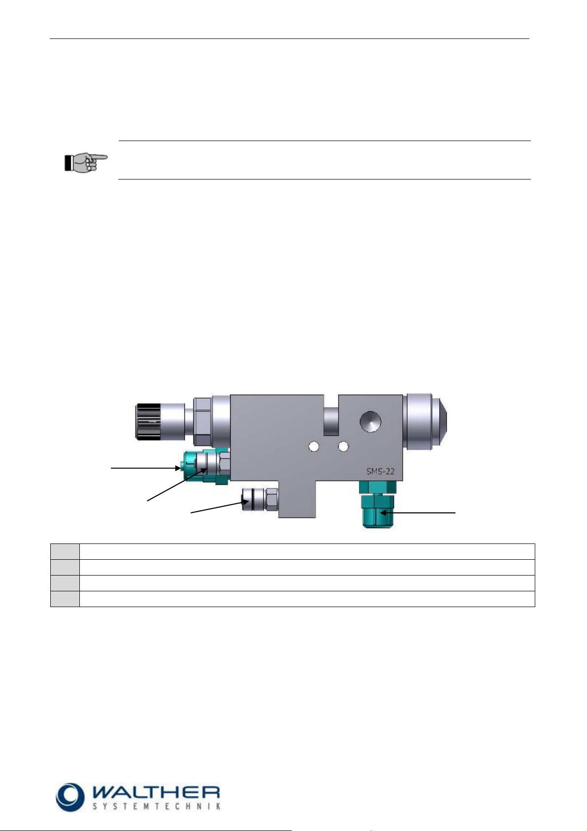
IMPORTANT
Make sure that spray valve/spraying device are safely and solidly fixed on the mounting
bracket or in the machine!
1
Material connection (M)
2
Compressed air connection – open control air (SL)
3
Compressed air connection – close control air (SL)
4
Atomizer air connection (ZL)
1 2 4
3
5 Mounting and First Start-up
The SMS-22 Spray Valve can be installed in any position.
The distance to the application area depends on the desired application width. The larger the distance of the
nozzle opening to the application area, the wider will be the actual application of material.
An intermitting operation of the device will cause natural oscillations; therefore a solid installation is most
important. Try to avoid excessive natural oscillations (transmission from device to valve).
5.1 Hose Mounting
There are three functional hoses for the supply of compressed air and material to the spray valve; they which
will be connected as follows (see figure on following page):
Atomizer air (blue)
Connection ZL: to 2/2-way magnetic valve
Control air (black)
Connection SL: close control air to 5/2-way magnetic valve
Control air (black)
Connection SL: open control air to 5/2-way magnetic valve
Material (transparent or white)
Connection M : to pressured container or pump
Unscrew safety cap from connection neck and slide over hose.
Place open hose end on the connection neck.
Put safety cap on connection neck and re-screw tightly.

Rev. 1.3
Assembly Instructions - Spray Valve SMS-22
Page 9 of 25
Walther Systemtechnik GmbH – D 76726 Germersheim
Telefon: +49 (0)7274-7022-0 Telefax: +49 (0)7274-7022-91
http://www.walther-2000.de – info@walther-2000.de
5.2 Total View / Description
1
Basic housing
2
Nozzle with air cap and retaining ring
3
Raster needle lock
4
Material connection
5
Atomizer air connection
6
Control air connection – open control air
7
Control air connection – close control air
8
2x fastening threads M5 (optional with center-sagging and centering bush for well-positioned installation)
9
Connection pressure sensor, optional (on top or on the right when looking in spray direction)
1 2 3 4 5 6 8 7 9
Control unit not included
in scope of delivery
5.3 Wiring Layout (separate control unit)

Rev. 1.3
Assembly Instructions - Spray Valve SMS-22
Page 10 of 25
Walther Systemtechnik GmbH – D 76726 Germersheim
Telefon: +49 (0)7274-7022-0 Telefax: +49 (0)7274-7022-91
http://www.walther-2000.de – info@walther-2000.de
5.4 Adjusting the Device
IMPORTANT
By turning the regulating screw you can adjust the material amount to the individual requirements:
Right turn: decreasing the material quantity
Left turn: increasing the material quantity
IMPORTANT
It is possible that the figures in this operating manual slightly deviate from the actual design
of the device. Nozzle and nozzle needle can be damaged by wrong handling. Never reduce
material quantity (right turn at the regulating screw) when no material is discharged. When
the nozzle is closed, do not attempt to turn the regulating screw further to the right.
CAUTION
Never point the jet at people. The wearing of eye protection is strongly recommended. The
spraying process can create noise depending on the air and fluid pressures used. Ear protection should be worn, if required.
WARNING
Danger caused by flammable, harmful fluid. Always follow the safety instructions on the container or the safety data sheet for the fluid.
IMPORTANT
In case high material pressures are required, make sure that the accident prevention
regulations of the trade associations will be strictly followed!
6 Operation
6.1 General Information
This device may only be operated if the safety-related equipment is permanently effective and not suspended during operation or altered in its intended effectiveness.
6.2 Operation Instructions / Operating Conditions
Spray valves of the SMS-22 series generally operate with a control pressure of 5 - 6 bar. The atomizer
pressure has to be lower than the material pressure in order to avoid a repulse of the material. Atomized air
pressure and material pressure should be closely correlated.
The control air pressure should be set at 5 – 6 bar.
The atomizer pressure has to be lower than the material pressure in order to avoid a repulse of the
material. Atomized air pressure and material pressure should be closely correlated. The atomizer air
will be controlled as follows: turn on before opening the needle and turn off after closing the needle
(guarantees broad maintenance-free operation).
For longer standstills, the material can remain in the valve, if it stays under pressure and if there is
no contact to outside air (only colors, abherents and oils). The material pressure in the hose,
however, should be decreased for greases in order to avoid any bleedings (oil separates).
Material and control air will only be used in clean, filtered condition. The control air should be slightly
greased when supplied to the spray valve/ spraying device.

Rev. 1.3
Assembly Instructions - Spray Valve SMS-22
Page 11 of 25
Walther Systemtechnik GmbH – D 76726 Germersheim
Telefon: +49 (0)7274-7022-0 Telefax: +49 (0)7274-7022-91
http://www.walther-2000.de – info@walther-2000.de
NOTE
Please follow the operating instructions!
NOTE
Please follow the maintenance instructions!
NOTE
Please follow the maintenance instructions!
Regulating Screw
6.3 Operating Elements
7 Taking out of Service
7.1 Short Interruption
A short interruption (15 min and more) will always be followed by a clean-spraying.
7.2 Long-term Interruption
The following will be observed for a long-term interruption of the device/machine:
Depressurize material supply lines
Take air cap (2.1/2.2) off and clean nozzle (3) with a special thinner and a soft cloth. Make sure that no
cloth fibers are left on the nozzle tip.
7.3 Shutdown of Device
The following is important for a shutdown of the machine / device:
Clean spray valve with a special thinner.

Rev. 1.3
Assembly Instructions - Spray Valve SMS-22
Page 12 of 25
Walther Systemtechnik GmbH – D 76726 Germersheim
Telefon: +49 (0)7274-7022-0 Telefax: +49 (0)7274-7022-91
http://www.walther-2000.de – info@walther-2000.de
CAUTION
Before starting any maintenance or repair work, ensure that all air-operated tools are
depressurized and disconnected from the air supply.
Before opening the spray valve it must be disconnected from the air and fluid supply.
Otherwise, ejected components can cause injuries.
IMPORTANT
Only use soft brushes for outside cleaning of the nozzle tips. Never use metal tools with
sharp edges.
IMPORTANT
Nozzle set = nozzle needle, nozzle and air cap (should always be replaced at the same
time)!
IMPORTANT
When installing nozzles and nozzle needles which have already been in use, rinse the nozzle with a suitable thinner to make sure that no residues of material remain. Also the needles
shaft will be thoroughly cleaned from residual particles. Needle shafts with cured material
can cause damages at the sealing element.
8 Maintenance and Repair
8.1 General Information
The spray valves of the SMS-22 series are high-quality precision devices which will not fail if treated correctly and will operate almost maintenance-free. All mobile parts should be regularly oiled and also the threads
should be greased when the nozzles are cleaned or exchanged. Always keep clean and observe minimum
instructions to maintain a long life of the valve. Always use clean and filtered material only. The control air
must also be clean and slightly oiled, if necessary. Maintenance also depends on the individual operating
conditions and the type of media used.
8.2 Cleaning
Wash equipment thoroughly after use to remove residues and dirt, especially if the nozzle needle (Pos.12),
the sealing sleeve (11.3) or the material nozzle (3) has to be exchanged.
8.3 Replacing the Nozzle and Nozzle Needle
First take pressure off all connections and disconnect material supply! Loosen retainer ring (1) and remove
air cap (2). Loosen locking screw (6). Important! Carefully remove locking screw as it is under spring
pressure! Carefully pull out nozzle needle (5) from main body (4). Unscrew nozzle (3) with open-end wrench
SW6. Slightly grease new nozzle needle (5) and insert. Carefully wipe off grease from needle tip. Screw in
new nozzle (3) with open-end wrench SW6. Important! Always replace nozzle (3) and nozzle needle (5)
at the same time. Screw tight locking screw (6). Put on air cap (2) and tighten with retainer ring (1).

Rev. 1.3
Assembly Instructions - Spray Valve SMS-22
Page 13 of 25
Walther Systemtechnik GmbH – D 76726 Germersheim
Telefon: +49 (0)7274-7022-0 Telefax: +49 (0)7274-7022-91
http://www.walther-2000.de – info@walther-2000.de
8.4 Replacing the Sealing Screw
IMPORTANT
Sealing and gaskets can be easily damaged. Therefore do not use any sharp-edged or metal
tools for removing and inserting the gaskets.
Take off pressure from all connections and disconnect material supply! Remove plastic sleeve (1). Loosen
locking screw (5). Important! Carefully remove locking screw as it is under spring pressure! Carefully
pull out nozzle needle (4) from main body (2). Loosen sealing screw (3) with a slot screwdriver and unscrew
from main body (2). Reassemble in reverse order.
8.5 Replacing the Sealing Elements of the Sealing Screw
Remove the old sealing elements (1,2,4) from the sealing screw (3). Carefully install the sealing elements
(1,2,4) with petrolatum on the sealing screw (3). Cover the sealing screw (3) with petrolatum so that sealing
elements will not be damaged when mounting the sealing screw in the main body.

Rev. 1.3
Assembly Instructions - Spray Valve SMS-22
Page 14 of 25
Walther Systemtechnik GmbH – D 76726 Germersheim
Telefon: +49 (0)7274-7022-0 Telefax: +49 (0)7274-7022-91
http://www.walther-2000.de – info@walther-2000.de
8.6 Spare Parts
IMPORTANT
Only use original spare parts from the manufacturer!
Wrong or defective spare parts from other manufacturers can damage the device. If other
than original spare parts of the manufacturer will be used, all obligations from the manufacturer or his sales partners, such as guarantees, service contracts etc will be forfeited without
further notice.
Walther Systemtechnik GmbH
Hockenheimer Straße 3
D-76726 Germersheim
Germany
Phone ++49(0)7274-7022-0
Telefax ++49(0)7274-7022-91
Email info@walther-2000.de
Internet www.walther-2000.de
IMPORTANT
First check all supply lines for connection and serviceability.
Failure
Possible cause
Action
Nozzle needle does
not open
Nozzle needle is sticky inside nozzle
sealing
Clean needle sealing completely
Control air pressure is too low
Check if sufficient control air pressure is
applied to the spray valve (see also 3.2
Technical Data)
Needle stroke too small
Increase needle stroke by turning the
raster screw
O-Ring (7.1 and 7.2, see 10.1.1) defective
Replace O-Ring
Pilot valve does not switch
Check pilot valve
No atomizer air
Atomizer air pressure is too low
Check if sufficient atomizer air pressure
is applied to the spray valve (see also
3.2 Technical Data)
No material discharge
Nozzle clogged by material
Clean nozzle and needle
Material pressure is too low
Check if sufficient material pressure is
applied at the spray valve
Spray image has errors
Air cap soiled
Clean air cap
Wrong air ratio
See also spray images/errors 9.3
8.7 Customer Service / Support
9 Troubleshooting
9.1 General Information
In case of serious problems that cannot be resolved, please contact the Walther Systemtechnik GmbH
customer service.
9.2 Malfunctions:

Rev. 1.3
Assembly Instructions - Spray Valve SMS-22
Page 15 of 25
Walther Systemtechnik GmbH – D 76726 Germersheim
Telefon: +49 (0)7274-7022-0 Telefax: +49 (0)7274-7022-91
http://www.walther-2000.de – info@walther-2000.de
9.3 Spray Images / Errors
SPRAY IMAGE
PROBLEM
CAUSE
ACTION
Normal spray image (flat jet)
Normal spray image (round jet)
Spray image shaped
too much
upwards and
downwards
Soiled air cap
Soiled nozzle
Clean nozzles
Spray image too much
left-sided or right-sided
Soiled
air cap
Soiled
nozzle
Clean nozzles
Heavy application in the
middle of the spray
image
Too much material
Material too thick
Reduce
material supply
Dilute material
Split
spray image
Too little material
Pressure flat jet too
high
Increase
material supply
Increase pressure
for round jet

Rev. 1.3
Assembly Instructions - Spray Valve SMS-22
Page 16 of 25
Walther Systemtechnik GmbH – D 76726 Germersheim
Telefon: +49 (0)7274-7022-0 Telefax: +49 (0)7274-7022-91
http://www.walther-2000.de – info@walther-2000.de
10 Appendix
10.1 Dimensioned Drawing SMS-22

Rev. 1.3
Assembly Instructions - Spray Valve SMS-22
Page 17 of 25
Walther Systemtechnik GmbH – D 76726 Germersheim
Telefon: +49 (0)7274-7022-0 Telefax: +49 (0)7274-7022-91
http://www.walther-2000.de – info@walther-2000.de
10.1.1 Spare Part Drawing SMS-22

Rev. 1.3
Assembly Instructions - Spray Valve SMS-22
Page 18 of 25
Walther Systemtechnik GmbH – D 76726 Germersheim
Telefon: +49 (0)7274-7022-0 Telefax: +49 (0)7274-7022-91
http://www.walther-2000.de – info@walther-2000.de
Fig.-No.
Art.-No.
Qty
Description
1.0
97410028
1
Retainer ring, 23 x 10mm
2.0 * 1
Air cap
3.0 * 1
Material nozzle
4.0
97510548
1
Main body SMS-22, 77 x 35 x 22mm, complete
97511883
1
Main body SMS-22, 77 x 35 x 22mm, complete with top hole 1/8"
97511814
1
Main body SMS-22, 77 x 35 x 22mm, complete with top hole 1/8" and
centering holes on the side
5.0
5.1
5.2
5.3
97640102
97640021
97640101
97640004
1
1
1
1
Material sealing kit
Plastic protective sleeve, ø10 x 6mm
Variseal 2,65 x 2,0 x 2,8
O-ring / Viton®
6.0
6.1
97810014
97810013
1
1
Sealing screw, complete, 11 x 21mm, Viton®
O-ring / Viton®
7.0
7.1
7.2
*
97640007
97640005
1
1
1
Sealing screw, complete, 3 x 72,5mm
O-ring / Viton®
O-ring / Viton® (LABS-free)
8.0
8.1
8.2
8.3
8.4
8.5
8.6
8.7
97900004
97610092
97220092
97640043
97930000
97820020
97640005
97710005
1
1
1
1
1
1
2
1
Raster needle lock, complete
Needle stroke-raster button ø15 x 29,5mm
Raster screw plug SW17 x 37mm
O-ring / Viton®
Thrust ring, 14,5 x 3mm
Pressure spring 1.1 x 22mm
O-ring / Viton® (LABS-free)
Closing piston
9.0
9.1
97511674
97640041
1
1
Control air connection for ext. controlling, 15 x 15mm
O-ring / Viton®
10.0
97610342
2
Cylinder screw DIN 7985 M3 x 18, black
11.0
97220022
97220552
2
Straight screw-in screw joint 1/8" - 6/4 KU
L-push-in fitting 1/8", 6/4
12.0
97220089
97220151
2
Screw joint, complete, 1/8" SW 8 x 19mm
Elbow gland pivoted, M5, VA
IMPORTANT
Always indicate the inscribed serial numbers when ordering spare parts!
10.1.2 Spare Part List for SMS-22 (Standard)
* Article numbers can be found on the following pages. All air caps, nozzles and nozzle needles are also
available in other materials upon request.
Please indicate the required size when ordering spare parts for nozzle sets (nozzle needle, nozzle and air
cap). Nozzle sets should always be replaced as a whole!

Rev. 1.3
Assembly Instructions - Spray Valve SMS-22
Page 19 of 25
Walther Systemtechnik GmbH – D 76726 Germersheim
Telefon: +49 (0)7274-7022-0 Telefax: +49 (0)7274-7022-91
http://www.walther-2000.de – info@walther-2000.de
10.2 Article Number for Air Caps
2.1
Air Cap, Round Jet, Standard, 15° (Ø20x11mm)
Article No.
Description
97310034
Air Cap, Round Jet, 0.2-1.0mm
97310035
Air Cap, Round Jet, 1.2mm-1.8mm
97310080
Air Cap, Round Jet, 2.0mm
97310091
Air Cap, Round Jet, 2.5mm
2.1
Air Cap, Round Jet, KLS, 15° (Ø20x11mm)
Article No.
Description
97310084
Air Cap, Round Jet, KLS 0.2-1.0mm
97310085
Air Cap, Round Jet, KLS 1.2-1.5mm
97310086
Air Cap, Round Jet, KLS 1.8-2.0mm
2.1
Marking Air cap, Round jet 8° (Ø20x18mm)
Article-No.
Description
97310578
Marking air cap, 0.2-0.5mm
97310727
Marking air cap, 0.8-1.0mm
2.1
Special spin air cap, round jet
Article No.
Description
97310197
Special spin 0.2-2.0mm
2.2
Air Cap, Flat Jet, Standard, 45° (Ø20x14.5mm)
Article No.
Description
97310038
Air Cap, Flat Jet, 0.2-1.0mm
97310039
Air Cap, Flat Jet, 1.2-1.8mm
97310231
Air Cap, Flat Jet, 1.8-2.0mm, 20 x 14.5mm
2.2
Air Cap, Flat Jet, Standard, 60° (Ø20x14.5mm)
Article No.
Description
97310032
Air Cap, Flat Jet, 0.2-1.0mm
97310033
Air Cap, Flat Jet, 1.2-1.8mm
97310079
Air Cap, Flat Jet, 2.0mm
97310090
Air Cap, Flat Jet, 2.5mm
2.2
Air Cap, Flat Jet, Standard, 90° (Ø20x14.5mm)
Article No.
Description
97310036
Air Cap, Flat Jet, 0.2-1.0mm
97310037
Air Cap, Flat Jet, 1.2-1.8mm
97310166
Air Cap, Flat Jet, 2.0mm
97310167
Air Cap, Flat Jet, 2.5mm

Rev. 1.3
Assembly Instructions - Spray Valve SMS-22
Page 20 of 25
Walther Systemtechnik GmbH – D 76726 Germersheim
Telefon: +49 (0)7274-7022-0 Telefax: +49 (0)7274-7022-91
http://www.walther-2000.de – info@walther-2000.de
2.2
Air Cap, Flat Jet, KLS, 45° (Ø20x14.5mm)
Article No.
Description
97310292
Air Cap, Flat Jet, KLS 0.2-1.0mm
97310546
Air Cap, Flat Jet, KLS 1.2-1.5mm
97310547
Air Cap, Flat Jet, KLS 1.8-2.0mm
2.2
Air Cap, Flat Jet, KLS, 60° (Ø20x14.5mm)
Article No.
Description
97310081
Air Cap, Flat Jet, KLS 0.2-1.0mm
97310082
Air Cap, Flat Jet, KLS 1.2-1.5mm
97310083
Air Cap, Flat Jet, KLS 1.8-2.0mm
2.2
Air Cap, Flat Jet, KLS, 90° (Ø20x14.5mm)
Article No.
Description
97310108
Air Cap, Flat Jet, KLS 0.2-1.0mm
97310211
Air Cap, Flat Jet, KLS 1.2-1.5mm
97310545
Air Cap, Flat Jet, KLS 1.8-2.0mm
2.2
Air Cap, unicorn, KLS, 45° (Ø20x14.5mm)
Article No.
Description
97310087
Air Cap, unicorn, KLS 0.2-1.0mm
97310088
Air Cap, unicorn, KLS 1.2-1.5mm
97310089
Air Cap, unicorn, KLS 1.8-2.0mm
3.0
Nozzle, Standard, stainless steel (Ø12x18mm)
Article No.
Description
97210110
Nozzle, Standard, 0.2mm
97210111
Nozzle, Standard, 0.3mm
97210112
Nozzle, Standard, 0.5mm
97210113
Nozzle, Standard, 0.8mm
97210114
Nozzle, Standard, 1.0mm
97210115
Nozzle, Standard, 1.2mm
97210116
Nozzle, Standard, 1.5mm
97210117
Nozzle, Standard, 2.0mm
97210118
Nozzle, Standard, 2.5mm
10.3 Article Numbers for Nozzles

Rev. 1.3
Assembly Instructions - Spray Valve SMS-22
Page 21 of 25
Walther Systemtechnik GmbH – D 76726 Germersheim
Telefon: +49 (0)7274-7022-0 Telefax: +49 (0)7274-7022-91
http://www.walther-2000.de – info@walther-2000.de
3.0
Nozzle, KLS, stainless steel (Ø12x17.2mm)
Article No.
Description
97210119
Nozzle, KLS, 0.2mm
97210120
Nozzle, KLS, 0.3mm
97210121
Nozzle, KLS, 0.5mm
97210122
Nozzle, KLS, 0.8mm
97210123
Nozzle, KLS, 1.0mm
97210124
Nozzle, KLS, 1.2mm
97210125
Nozzle, KLS, 1.5mm
97210126
Nozzle, KLS, 2.0mm
97210564
Nozzle, KLS, 2.5mm
3.0
Marking Nozzle, stainless steel 8°(Ø8x18mm)
Article No.
Description
97212055
Marking nozzle 0.2mm
97211875
Marking nozzle 0.3mm
97212025
Marking nozzle 0.4mm
97211461
Marking nozzle 0.5mm
97212146
Marking nozzle 0.8mm
3.0
Nozzle, special spin, stainless steel (Ø12x18mm)
Article No.
Description
97210483
Nozzle, special spin, 0.2mm
97210484
Nozzle, special spin, 0.3mm
97210482
Nozzle, special spin, 0.5mm
97210485
Nozzle, special spin, 0.8mm
97211030
Nozzle, special spin, 1.0mm
97212510
Nozzle, special spin, 1.5mm
97212397
Nozzle, special spin, 2.0mm
7.0
Nozzle Needle complete, Standard, Marking, Special
spin (Ø3x72.5mm)
Article No.
Description
97112508
Nozzle Needle, Standard, 0.2/0.3mm
97110471
Nozzle Needle, Standard, 0.5mm
97111251
Nozzle Needle, Standard, 0.8mm
97111079
Nozzle Needle, Standard, 1.0mm
97112506
Nozzle Needle, Standard, 1.2mm
97112388
Nozzle Needle, Standard, 1.5mm
97111069
Nozzle Needle, Standard, 1.8/2.0mm
97111171
Nozzle Needle, Standard, 2.5mm
10.4 Article Numbers for Nozzle Needles

Rev. 1.3
Assembly Instructions - Spray Valve SMS-22
Page 22 of 25
Walther Systemtechnik GmbH – D 76726 Germersheim
Telefon: +49 (0)7274-7022-0 Telefax: +49 (0)7274-7022-91
http://www.walther-2000.de – info@walther-2000.de
7.0
Nozzle Needle complete, KLS, (Ø3x72.5mm)
Article No.
Description
97110187
Nozzle Needle, KLS, 0.2/0.3mm
97110188
Nozzle Needle, KLS, 0.5mm
97110189
Nozzle Needle, KLS, 0.8/1.0mm
97110190
Nozzle Needle, KLS, 1.2mm
97110191
Nozzle Needle, KLS, 1.5mm
97110192
Nozzle Needle, KLS, 2.0mm
97111301
Nozzle Needle, KLS, 2.5mm
Material Wear-and-tear Kit complete for SMS-22
Consisting of:
# Pos. 9.1 (O-ring)
# Pos. 5.2 (Variseal)
# Pos. 5.3 (O-ring)
# Pos. 5.1 (protective sleeve)
# Pos. 6.1 (O-ring)
# Pos. 7.1 (O-ring)
Article No.
Description
979504.009
Material Wear-and-tear Kit for SMS-22, VITON
10.5 Wear-and-tear Parts Kits

Rev. 1.3
Assembly Instructions - Spray Valve SMS-22
Page 23 of 25
Walther Systemtechnik GmbH – D 76726 Germersheim
Telefon: +49 (0)7274-7022-0 Telefax: +49 (0)7274-7022-91
http://www.walther-2000.de – info@walther-2000.de
10.6 Accessories
Figure
Article Number
Description
97xxxxxx
Nozzle extension
(see also Product Catalog ACCESSORIES)
97410042
Retainer ring hexagonal
97410059
Retainer ring stainless steel
979565.001
Hotplate
(see also Product Catalog ACCESSORIES)
97PA21G-XX
Pressure sensor
(see also Product Catalog „Checking“)
97947xxx
Counter
(see also Product Catalog ACCESSORIES)
979565.001Z002Z
Insulating profile (without heating)
979444
Cleaning set
(see also Product catalog ACCESSORIES)
97321082
Centering bush

Rev. 1.3
Assembly Instructions - Spray Valve SMS-22
Page 24 of 25
Walther Systemtechnik GmbH – D 76726 Germersheim
Telefon: +49 (0)7274-7022-0 Telefax: +49 (0)7274-7022-91
http://www.walther-2000.de – info@walther-2000.de
Figure
Article Number
Description
97320602
Centering sleeve for an exact positioning of the valve
WICHTIG
If a Centering sleeve is retrofitted to an existing valve, the valve must be returned to us for
retrofitting of Center hole.
10.6.1 Center hole for Centering sleeve 97320602

Rev. 1.3
Assembly Instructions - Spray Valve SMS-22
Page 25 of 25
Walther Systemtechnik GmbH – D 76726 Germersheim
Telefon: +49 (0)7274-7022-0 Telefax: +49 (0)7274-7022-91
http://www.walther-2000.de – info@walther-2000.de
10.6.2 Add-on Elements
Pos.
Description
1
Pressure sensor mounted on top of the spray valve
2
Pressure sensor mounted at the right side of the spray valve
3
2 1 3
Pressure Sensor
The installation of the pressure sensor will be made factory-side. Its actual position can be either at the side
(left or right) or on top. Please refer to the assembly instructions „Pressure Sensors 97PA-21x-xxx“ for additional information.
Heating Plate
The heating plate (3) will be mounted factory-side. Its actual position will be at the side (left / right). Please
see the description „Heating and Accessories“ for additional information.
 Loading...